EP2805878B1 - Grätschsitz-Fahrzeug - Google Patents
Grätschsitz-Fahrzeug Download PDFInfo
- Publication number
- EP2805878B1 EP2805878B1 EP14160671.5A EP14160671A EP2805878B1 EP 2805878 B1 EP2805878 B1 EP 2805878B1 EP 14160671 A EP14160671 A EP 14160671A EP 2805878 B1 EP2805878 B1 EP 2805878B1
- Authority
- EP
- European Patent Office
- Prior art keywords
- exhaust
- pipe
- cylinder
- exhaust pipe
- pipes
- Prior art date
- Legal status (The legal status is an assumption and is not a legal conclusion. Google has not performed a legal analysis and makes no representation as to the accuracy of the status listed.)
- Active
Links
Images




Classifications
-
- F—MECHANICAL ENGINEERING; LIGHTING; HEATING; WEAPONS; BLASTING
- F02—COMBUSTION ENGINES; HOT-GAS OR COMBUSTION-PRODUCT ENGINE PLANTS
- F02B—INTERNAL-COMBUSTION PISTON ENGINES; COMBUSTION ENGINES IN GENERAL
- F02B75/00—Other engines
- F02B75/16—Engines characterised by number of cylinders, e.g. single-cylinder engines
- F02B75/18—Multi-cylinder engines
- F02B75/20—Multi-cylinder engines with cylinders all in one line
-
- B—PERFORMING OPERATIONS; TRANSPORTING
- B62—LAND VEHICLES FOR TRAVELLING OTHERWISE THAN ON RAILS
- B62M—RIDER PROPULSION OF WHEELED VEHICLES OR SLEDGES; POWERED PROPULSION OF SLEDGES OR SINGLE-TRACK CYCLES; TRANSMISSIONS SPECIALLY ADAPTED FOR SUCH VEHICLES
- B62M7/00—Motorcycles characterised by position of motor or engine
- B62M7/02—Motorcycles characterised by position of motor or engine with engine between front and rear wheels
-
- F—MECHANICAL ENGINEERING; LIGHTING; HEATING; WEAPONS; BLASTING
- F01—MACHINES OR ENGINES IN GENERAL; ENGINE PLANTS IN GENERAL; STEAM ENGINES
- F01N—GAS-FLOW SILENCERS OR EXHAUST APPARATUS FOR MACHINES OR ENGINES IN GENERAL; GAS-FLOW SILENCERS OR EXHAUST APPARATUS FOR INTERNAL-COMBUSTION ENGINES
- F01N13/00—Exhaust or silencing apparatus characterised by constructional features
- F01N13/08—Other arrangements or adaptations of exhaust conduits
-
- F—MECHANICAL ENGINEERING; LIGHTING; HEATING; WEAPONS; BLASTING
- F01—MACHINES OR ENGINES IN GENERAL; ENGINE PLANTS IN GENERAL; STEAM ENGINES
- F01N—GAS-FLOW SILENCERS OR EXHAUST APPARATUS FOR MACHINES OR ENGINES IN GENERAL; GAS-FLOW SILENCERS OR EXHAUST APPARATUS FOR INTERNAL-COMBUSTION ENGINES
- F01N13/00—Exhaust or silencing apparatus characterised by constructional features
- F01N13/08—Other arrangements or adaptations of exhaust conduits
- F01N13/10—Other arrangements or adaptations of exhaust conduits of exhaust manifolds
-
- F—MECHANICAL ENGINEERING; LIGHTING; HEATING; WEAPONS; BLASTING
- F02—COMBUSTION ENGINES; HOT-GAS OR COMBUSTION-PRODUCT ENGINE PLANTS
- F02B—INTERNAL-COMBUSTION PISTON ENGINES; COMBUSTION ENGINES IN GENERAL
- F02B27/00—Use of kinetic or wave energy of charge in induction systems, or of combustion residues in exhaust systems, for improving quantity of charge or for increasing removal of combustion residues
- F02B27/04—Use of kinetic or wave energy of charge in induction systems, or of combustion residues in exhaust systems, for improving quantity of charge or for increasing removal of combustion residues in exhaust systems only, e.g. for sucking-off combustion gases
-
- F—MECHANICAL ENGINEERING; LIGHTING; HEATING; WEAPONS; BLASTING
- F02—COMBUSTION ENGINES; HOT-GAS OR COMBUSTION-PRODUCT ENGINE PLANTS
- F02B—INTERNAL-COMBUSTION PISTON ENGINES; COMBUSTION ENGINES IN GENERAL
- F02B61/00—Adaptations of engines for driving vehicles or for driving propellers; Combinations of engines with gearing
- F02B61/02—Adaptations of engines for driving vehicles or for driving propellers; Combinations of engines with gearing for driving cycles
-
- F—MECHANICAL ENGINEERING; LIGHTING; HEATING; WEAPONS; BLASTING
- F02—COMBUSTION ENGINES; HOT-GAS OR COMBUSTION-PRODUCT ENGINE PLANTS
- F02M—SUPPLYING COMBUSTION ENGINES IN GENERAL WITH COMBUSTIBLE MIXTURES OR CONSTITUENTS THEREOF
- F02M35/00—Combustion-air cleaners, air intakes, intake silencers, or induction systems specially adapted for, or arranged on, internal-combustion engines
- F02M35/10—Air intakes; Induction systems
- F02M35/10006—Air intakes; Induction systems characterised by the position of elements of the air intake system in direction of the air intake flow, i.e. between ambient air inlet and supply to the combustion chamber
- F02M35/10072—Intake runners
-
- F—MECHANICAL ENGINEERING; LIGHTING; HEATING; WEAPONS; BLASTING
- F02—COMBUSTION ENGINES; HOT-GAS OR COMBUSTION-PRODUCT ENGINE PLANTS
- F02M—SUPPLYING COMBUSTION ENGINES IN GENERAL WITH COMBUSTIBLE MIXTURES OR CONSTITUENTS THEREOF
- F02M35/00—Combustion-air cleaners, air intakes, intake silencers, or induction systems specially adapted for, or arranged on, internal-combustion engines
- F02M35/10—Air intakes; Induction systems
- F02M35/10091—Air intakes; Induction systems characterised by details of intake ducts: shapes; connections; arrangements
-
- F—MECHANICAL ENGINEERING; LIGHTING; HEATING; WEAPONS; BLASTING
- F02—COMBUSTION ENGINES; HOT-GAS OR COMBUSTION-PRODUCT ENGINE PLANTS
- F02M—SUPPLYING COMBUSTION ENGINES IN GENERAL WITH COMBUSTIBLE MIXTURES OR CONSTITUENTS THEREOF
- F02M35/00—Combustion-air cleaners, air intakes, intake silencers, or induction systems specially adapted for, or arranged on, internal-combustion engines
- F02M35/10—Air intakes; Induction systems
- F02M35/104—Intake manifolds
- F02M35/112—Intake manifolds for engines with cylinders all in one line
-
- F—MECHANICAL ENGINEERING; LIGHTING; HEATING; WEAPONS; BLASTING
- F02—COMBUSTION ENGINES; HOT-GAS OR COMBUSTION-PRODUCT ENGINE PLANTS
- F02M—SUPPLYING COMBUSTION ENGINES IN GENERAL WITH COMBUSTIBLE MIXTURES OR CONSTITUENTS THEREOF
- F02M35/00—Combustion-air cleaners, air intakes, intake silencers, or induction systems specially adapted for, or arranged on, internal-combustion engines
- F02M35/16—Combustion-air cleaners, air intakes, intake silencers, or induction systems specially adapted for, or arranged on, internal-combustion engines characterised by use in vehicles
- F02M35/162—Motorcycles; All-terrain vehicles, e.g. quads, snowmobiles; Small vehicles, e.g. forklifts
-
- F—MECHANICAL ENGINEERING; LIGHTING; HEATING; WEAPONS; BLASTING
- F01—MACHINES OR ENGINES IN GENERAL; ENGINE PLANTS IN GENERAL; STEAM ENGINES
- F01N—GAS-FLOW SILENCERS OR EXHAUST APPARATUS FOR MACHINES OR ENGINES IN GENERAL; GAS-FLOW SILENCERS OR EXHAUST APPARATUS FOR INTERNAL-COMBUSTION ENGINES
- F01N2340/00—Dimensional characteristics of the exhaust system, e.g. length, diameter or volume of the exhaust apparatus; Spatial arrangements of exhaust apparatuses
- F01N2340/04—Arrangement of the exhaust system relative to a vehicle or parts thereof
-
- F—MECHANICAL ENGINEERING; LIGHTING; HEATING; WEAPONS; BLASTING
- F01—MACHINES OR ENGINES IN GENERAL; ENGINE PLANTS IN GENERAL; STEAM ENGINES
- F01N—GAS-FLOW SILENCERS OR EXHAUST APPARATUS FOR MACHINES OR ENGINES IN GENERAL; GAS-FLOW SILENCERS OR EXHAUST APPARATUS FOR INTERNAL-COMBUSTION ENGINES
- F01N2470/00—Structure or shape of exhaust gas passages, pipes or tubes
- F01N2470/20—Dimensional characteristics of tubes, e.g. length, diameter
-
- F—MECHANICAL ENGINEERING; LIGHTING; HEATING; WEAPONS; BLASTING
- F01—MACHINES OR ENGINES IN GENERAL; ENGINE PLANTS IN GENERAL; STEAM ENGINES
- F01N—GAS-FLOW SILENCERS OR EXHAUST APPARATUS FOR MACHINES OR ENGINES IN GENERAL; GAS-FLOW SILENCERS OR EXHAUST APPARATUS FOR INTERNAL-COMBUSTION ENGINES
- F01N2590/00—Exhaust or silencing apparatus adapted to particular use, e.g. for military applications, airplanes, submarines
- F01N2590/04—Exhaust or silencing apparatus adapted to particular use, e.g. for military applications, airplanes, submarines for motorcycles
-
- F—MECHANICAL ENGINEERING; LIGHTING; HEATING; WEAPONS; BLASTING
- F02—COMBUSTION ENGINES; HOT-GAS OR COMBUSTION-PRODUCT ENGINE PLANTS
- F02B—INTERNAL-COMBUSTION PISTON ENGINES; COMBUSTION ENGINES IN GENERAL
- F02B75/00—Other engines
- F02B75/16—Engines characterised by number of cylinders, e.g. single-cylinder engines
- F02B75/18—Multi-cylinder engines
- F02B2075/1804—Number of cylinders
- F02B2075/1812—Number of cylinders three
-
- Y—GENERAL TAGGING OF NEW TECHNOLOGICAL DEVELOPMENTS; GENERAL TAGGING OF CROSS-SECTIONAL TECHNOLOGIES SPANNING OVER SEVERAL SECTIONS OF THE IPC; TECHNICAL SUBJECTS COVERED BY FORMER USPC CROSS-REFERENCE ART COLLECTIONS [XRACs] AND DIGESTS
- Y02—TECHNOLOGIES OR APPLICATIONS FOR MITIGATION OR ADAPTATION AGAINST CLIMATE CHANGE
- Y02T—CLIMATE CHANGE MITIGATION TECHNOLOGIES RELATED TO TRANSPORTATION
- Y02T10/00—Road transport of goods or passengers
- Y02T10/10—Internal combustion engine [ICE] based vehicles
- Y02T10/12—Improving ICE efficiencies
Definitions
- the present invention relates to a straddle-type vehicle according to the preamble of independent claim 1.
- a straddle-type vehicle can be taken from the prior art document EP 1 767 446 A2 .
- EP 0 441 461 A2 discloses an air intake system adapted for motor bicycle engine that includes intake pipes having different lengths.
- a straddle-type vehicle including an engine in which three cylinders are arranged in alignment with each other in a lateral direction of the vehicle, i.e., a "parallel three cylinder engine”, is conventionally known.
- JP 2007-83849 A discloses a motorcycle including a parallel three cylinder engine.
- the parallel three cylinder engine disclosed in JP 2007-83849 A includes three exhaust pipes in communication with three cylinders.
- the exhaust pipes are first extended forward and then bent leftward and downward in a front view of the motorcycle so as to be connected to a bundle portion into which the exhaust pipes are collected.
- a muffler is connected to the bundle portion.
- a straddle-type vehicle includes an internal combustion engine that includes a first cylinder, a second cylinder disposed leftward of the first cylinder in a front view of the vehicle, and a third cylinder disposed leftward of the second cylinder in the front view of the vehicle; a first intake pipe in communication with the first cylinder, a second intake pipe in communication with the second cylinder, and a third intake pipe in communication with the third cylinder; and a first exhaust pipe in communication with the first cylinder, a second exhaust pipe in communication with the second cylinder, and a third exhaust pipe in communication with the third cylinder.
- the first, second, and third exhaust pipes have different lengths.
- the first, second, and third intake pipes have different lengths.
- the lengths of the first, second, and third exhaust pipes are easily prevented from being complicated in shape.
- the lengths of the first, second, and third exhaust pipes are different from each other, it is likely that there will occur combustion variations between the cylinders of the internal combustion engine.
- the lengths of the first, second, and third intake pipes are also different from each other.
- the parallel three cylinder engine is allowed to deliver its original performance without equalizing the lengths of the first, second, and third exhaust pipes.
- the shortest of the first, second, and third intake pipes is in communication with the cylinder with which the longest of the first, second, and third exhaust pipes is in communication.
- the longest of the first, second, and third intake pipes is in communication with the cylinder with which the shortest of the first, second, and third exhaust pipes is in communication.
- the longest of the first, second, and third exhaust pipes preferably is the second exhaust pipe.
- each of the first, second, and third exhaust pipes is capable of being disposed at a suitable position.
- the straddle-type vehicle preferably further includes an air cleaner connected to the first, second, and third intake pipes.
- the first, second, and third intake pipes have different lengths, but are connected to the same air cleaner.
- the air cleaner preferably includes a first insertion opening into which the first intake pipe is inserted, a second insertion opening into which the second intake pipe is inserted, and a third insertion opening into which the third intake pipe is inserted.
- the first intake pipe preferably includes a first opening end disposed inside the air cleaner
- the second intake pipe preferably includes a second opening end disposed inside the air cleaner
- the third intake pipe preferably includes a third opening end disposed inside the air cleaner.
- a length of the first intake pipe from the first insertion opening to the first opening end, a length of the second intake pipe from the second insertion opening to the second opening end, and a length of the third intake pipe from the third insertion opening to the third opening end are preferably different from each other.
- lengths of portions of the first, second, and third intake pipes which are located outside of the air cleaner do not necessarily have to be different from each other. Consequently, flexibility of locating the first, second, and third intake pipes is increased.
- the internal combustion engine preferably includes a crankcase; a cylinder body that contains the first, second, and third cylinders and is connected to the crankcase; and a cylinder head to which the first, second, and third intake pipes and the first, second, and third exhaust pipes are connected, the cylinder head being connected to the cylinder body.
- the straddle-type vehicle preferably includes an exhaust manifold which is disposed below the crankcase and to which the first, second, and third exhaust pipes are connected.
- the exhaust manifold is disposed below the crankcase and, therefore, an overall lateral length of the internal combustion engine and the exhaust manifold are shorter than when the exhaust manifold is disposed rightward or leftward of the crankcase.
- the first cylinder is preferably disposed rightward of a vehicle center line in the front view of the vehicle
- the third cylinder is preferably disposed leftward of the vehicle center line in the front view of the vehicle.
- the exhaust manifold is preferably disposed rightward or leftward of the vehicle center line in the front view of the vehicle.
- the exhaust manifold is disposed so as to be deviated to the right or left from the vehicle center line.
- the exhaust manifold is disposed so as to be deviated to the right or left from the vehicle center line.
- the exhaust manifold is preferably disposed closer to the first end than the vehicle center line.
- the first exhaust pipe preferably includes a portion located closer to the second end than an axis of the first cylinder
- the second exhaust pipe preferably includes a portion located closer to the second end than an axis of the second cylinder
- the third exhaust pipe preferably includes a portion located closer to the second end than an axis of the third cylinder.
- each exhaust pipe has such a shape so as to extend rightward and then extend leftward in the front view of the vehicle, or has such a shape so as to extend leftward and then extend rightward in the front view of the vehicle. Therefore, the length of each exhaust pipe is sufficiently ensured within a small space around the crankcase, the cylinder body, and the cylinder head. As a result, the first, second, and third exhaust pipes are compactly disposed while the original performance of the parallel three cylinder engine is maintained.
- each of the first, second, and third exhaust pipes preferably includes a connection that is connected to the exhaust manifold.
- the connection of the longest of the first, second, and third exhaust pipes is preferably disposed below the connections of the other two exhaust pipes.
- the first, second, and third exhaust pipes are not restricted to being equal in length, and therefore, the connections of the first, second, and third exhaust pipes are easily disposed at such positions.
- the lateral length of the exhaust manifold is shorter than when the connections of the first, second, and third exhaust pipes are arranged in alignment with each other in a lateral direction of the vehicle.
- At least one of the first, second, and third exhaust pipes preferably includes a portion that overlaps with the axis of the cylinder with which the adjacent exhaust pipe is in communication.
- the straddle-type vehicle preferably further includes a first connection pipe connected to the first exhaust pipe and the second exhaust pipe, and a second connection pipe connected to the second exhaust pipe and the third exhaust pipe.
- the first exhaust pipe and the second exhaust pipe are in communication with each other through the first connection pipe, and the second exhaust pipe and the third exhaust pipe are in communication with each other through the second connection pipe.
- the first connection pipe preferably includes a first connection connected to a portion of the first exhaust pipe which is located upstream of a midpoint position of the first exhaust pipe, and a second connection connected to a portion of the second exhaust pipe which is located upstream of a midpoint position of the second exhaust pipe.
- the second connection pipe preferably includes a first connection connected to a portion of the second exhaust pipe which is located upstream of the midpoint position of the second exhaust pipe, and a second connection connected to a portion of the third exhaust pipe which is located upstream of a midpoint position of the third exhaust pipe.
- pressure fluctuations in the first, second, and third exhaust pipes are reduced in farther upstream regions thereof.
- fluctuations in the output torque of the internal combustion engine are more effectively reduced.
- the straddle-type vehicle may be a motorcycle.
- Various preferred embodiments of the present invention provide a straddle-type vehicle that includes a parallel three cylinder engine capable of delivering its original performance without equalizing lengths of exhaust pipes.
- FIG. 1 is a left side view of a motorcycle (straddle-type vehicle) 1 according to a preferred embodiment of the present invention
- FIG. 2 is a right side view of the motorcycle 1.
- "front”, “rear”, “right”, “left”, “up” and “down” indicate front, rear, right, left, up and down with respect to a rider sitting on a seat 11 of the motorcycle 1, respectively.
- "Up” and “down” correspond to a vertically upward direction and a vertically downward direction when the motorcycle 1 is brought to a stop on a horizontal plane, respectively.
- Reference signs “F”, “Re”, “R”, “L”, “Up” and “Dn” in the drawings represent front, rear, right, left, up and down, respectively.
- directions defined as viewed from the front of the vehicle may also be used in the following description.
- right and left are reversed.
- left and right defined as viewed from the front of the vehicle correspond to right and left defined with respect to the rider sitting on the seat 11, respectively.
- Reference signs "R"' and "L”' indicate right and left defined as viewed from the front of the vehicle.
- the motorcycle 1 preferably includes a head pipe 2.
- a handlebar 3 is supported by the head pipe 2 so that the handlebar 3 can be turned to the right and left.
- a front fork 4 is connected to a lower end portion of the handlebar 3.
- a front wheel 5 is rotatably supported by a lower end portion of the front fork 4.
- a body frame 6 is fixed to the head pipe 2.
- the body frame 6 preferably includes a main frame 7 that extends obliquely downward and rearward from the head pipe 2 in a side view of the vehicle, a seat frame 8 that extends obliquely upward and rearward from the main frame 7 in the side view of the vehicle, and a back stay 9 connected to the main frame 7 and the seat frame 8.
- a fuel tank 10 is disposed rearward of the head pipe 2, and the seat 11 is disposed rearward of the fuel tank 10.
- the fuel tank 10 and the seat 11 are supported by the body frame 6.
- a rear arm 13 is rotatably supported by the main frame 7.
- a front end portion of the rear arm 13 is connected to the main frame 7 via a pivot shaft 12.
- a rear wheel 14 is rotatably supported by a rear end portion of the rear arm 13.
- the internal combustion engine 20 is supported by the body frame 6.
- the internal combustion engine 20 is preferably a "parallel three cylinder engine” as will be described below, for example.
- the internal combustion engine 20 will simply be referred to as the "engine 20".
- the engine 20 preferably includes a crankcase 22, a cylinder body 24 that extends obliquely upward and forward from the crankcase 22, a cylinder head 26 that extends obliquely upward and forward from the cylinder body 24, and a head cover 28 connected to a front end portion of the cylinder head 26.
- the cylinder body 24 preferably is integral with the crankcase 22.
- the cylinder body 24 and the crankcase 22 may be separate components.
- the engine 20 preferably includes a drive shaft 46 that outputs a driving force.
- the drive shaft 46 is connected to the rear wheel 14 via a chain 15.
- a first cylinder 31, a second cylinder 32, and a third cylinder 33 are provided inside the cylinder body 24.
- the first, second, and third cylinders 31, 32 and 33 are disposed, in this order, from left to right.
- the first, second, and third cylinders 31, 32, and 33 are disposed in this order from right to left in the front view of the vehicle.
- the first, second, and third cylinders 31, 32, and 33 are arranged in alignment with each other in a lateral direction of the motorcycle 1.
- a piston 34 is contained in each of the first, second, and third cylinders 31, 32, and 33.
- Each piston 34 is connected to a crankshaft 36 via a connecting rod 35.
- the crankshaft 36 is contained in the crankcase 22.
- Concaves 27 are provided in portions of the cylinder head 26 which are located above the first, second, and third cylinders 31, 32, and 33.
- the cylinders 31 to 33, the pistons 34, and the concaves 27 define combustion chambers 43.
- the cylinder head 26 is provided with intake ports 95 (see FIG. 5 ) and exhaust ports 96 (see FIGS. 5 and 6 ) which are in communication with the combustion chambers 43.
- a generator 37 is attached to a left end portion of the crankshaft 36.
- a sprocket 39 is attached to a right end portion of the crankshaft 36.
- a cam chain 41 is wound around the sprocket 39.
- a gear 42 is fixed to a portion of the crankshaft 36 which is located leftward of the sprocket 39.
- the engine 20 preferably includes a clutch 38.
- the clutch 38 preferably includes a clutch housing 38a and a clutch boss 38b.
- the clutch housing 38a is connected to the gear 42.
- a torque of the crankshaft 36 is transmitted to the clutch housing 38a via the gear 42.
- the clutch housing 38a rotates together with the crankshaft 36.
- a main shaft 44 is fixed to the clutch boss 38b.
- the engine 20 preferably includes a transmission 40.
- the transmission 40 preferably includes a plurality of gears 45 provided at the main shaft 44, a plurality of gears 47 provided at the drive shaft 46, a shift drum 48, and a shift fork 49.
- the shift fork 49 causes the gears 45 and/or the gears 47 to move axially, thus changing a combination of the gears 45 and 47 which intermesh with each other. As a result, a transmission gear ratio is changed.
- the engine 20 preferably includes a balancer 90.
- the balancer 90 preferably includes a balancer shaft 91, and a balancer weight 92 provided at the balancer shaft 91.
- a gear 93 that intermeshes with the gear 42 is fixed to a right portion of the balancer shaft 91.
- the balancer shaft 91 is connected to the crankshaft 36 via the gear 42 and the gear 93.
- the balancer shaft 91 is driven by the crankshaft 36, and is rotated together with the crankshaft 36.
- a gear 94 is fixed to a left end portion of the balancer shaft 91.
- the gear 42 is preferably press-fitted to the crankshaft 36. As mentioned above, the gear 42 intermeshes with both of the clutch housing 38a of the clutch 38 and the gear 93 of the balancer 90.
- the gear 42 preferably includes a press-fitted gear, thus making it possible to reduce an outer diameter of the gear 42. A reduction in the outer diameter of the gear 42 reduces a distance between the crankshaft 36 and the main shaft 44 and a distance between the crankshaft 36 and the balancer shaft 91. Note that the crankshaft 36, the main shaft 44, the drive shaft 46 and the balancer shaft 91 extend laterally (i.e., extend in a right-left direction), and are disposed parallel, or substantially parallel, to each other.
- the engine 20 is preferably a water-cooled internal combustion engine, in which at least a portion of which is cooled by cooling water, for example.
- the engine 20 preferably includes a water pump 52 (see FIG. 6 ) that conveys cooling water, a radiator 54 (see FIG. 7 ) that cools the cooling water, a thermostat 58 (see FIGS. 6 and 7 ), and an oil cooler 56 (see FIGS. 6 and 7 ).
- the water pump 52 preferably includes, a pump shaft 62, and an impeller 61 fixed to the pump shaft 62.
- a gear 63 that intermeshes with the gear 94 is fixed to the pump shaft 62.
- the water pump 52 is arranged so as to be driven by the balancer shaft 91.
- each intake port 95 preferably includes an inner end portion 95a and an outer end portion 95b.
- the inner end portion 95a faces the combustion chamber 43.
- An intake valve 65 is disposed in the intake port 95.
- the intake valve 65 is arranged to open and close the inner end portion 95a of the intake port 95.
- a fuel injection valve 67 is disposed between the inner end portion 95a and the outer end portion 95b of the intake port 95.
- the fuel injection valve 67 injects fuel into the intake port 95.
- a fuel supply device of the engine 20 is not limited to the fuel injection valve 67 that injects fuel into the intake port 95, but may alternatively be a fuel injection valve that injects fuel into the combustion chamber 43.
- the fuel supply device is not limited to a fuel injection valve, but may alternatively be a carburetor.
- a throttle body 53 that contains a throttle valve 29 is connected to the outer end portion 95b of the intake port 95.
- the throttle valve 29 is provided for each of the cylinders 31 to 33.
- the engine 20 includes the three cylinders 31 to 33 and therefore includes three throttle valves 29.
- the throttle bodies 53 that contain the throttle valves 29 may be separate components or may be integral with each other. In the present preferred embodiment, the throttle bodies 53 preferably are separate components, and the three throttle bodies 53 in total are disposed from right to left, for example.
- a first intake pipe 121, a second intake pipe 122, and a third intake pipe 123 are connected to the right, center, and left throttle bodies 53 in the front view of the vehicle, respectively.
- the first, second, and third intake pipes 121, 122, and 123 are in communication with the first, second, and third cylinders 31, 32, and 33, respectively.
- the first, second, and third intake pipes 121, 122, and 123 are disposed in this order from right to left and extend upward in the front view of the vehicle.
- the intake pipes 121 to 123 extend obliquely upward and rearward from the throttle bodies 53 and then bend obliquely upward and forward in the side view of the vehicle.
- An end portion of each of the intake pipes 121 to 123 has a funnel-like shape. In other words, the end portion of each of the intake pipes 121 to 123 has an increased diameter toward its extremity.
- the air cleaner 59 is disposed above the cylinder head 26 and the head cover 28.
- the air cleaner 59 preferably includes a lower case 59A, an upper case 59B fixed to the lower case 59A, and an element 59C disposed inside the lower case 59A and the upper case 59B.
- the lower case 59A and the upper case 59B define an air cleaner case 59D.
- the air cleaner case 59D is not limited to any particular constituent component(s).
- Three insertion openings 59d are provided in a rear portion of the air cleaner case 59D. In this preferred embodiment, the insertion openings 59d are provided in the lower case 59A. Alternatively, the insertion openings 59d may be provided in the upper case 59B.
- the three insertion openings 59d are arranged from right to left in the front view of the vehicle.
- the first intake pipe 121 is inserted into the right insertion opening 59d
- the second intake pipe 122 is inserted into the center insertion opening 59d
- the third intake pipe 123 is inserted into the left insertion opening 59d.
- the terms "right” , “center” and “left” used for the insertion openings 59d refer to right, center and left in the front view of the vehicle, respectively.
- An opening end 121a of the first intake pipe 121, an opening end 122a of the second intake pipe 122, and an opening end 123a of the third intake pipe 123 are opened inside the air cleaner case 59D.
- lengths of the three intake pipes 121 to 123 from the insertion openings 59d to the opening ends 121a to 123a are different from each other. More specifically, a length L2 between the opening end 122a of the second intake pipe 122 and the center insertion opening 59d is shorter than a length L1 between the opening end 121a of the first intake pipe 121 and the right insertion opening 59d.
- a length L3 between the opening end 123a of the third intake pipe 123 and the left insertion opening 59d is longer than the length L1 between the opening end 121a of the first intake pipe 121 and the right insertion opening 59d.
- each of the first, second, and third intake pipes 121, 122, and 123 preferably includes a portion located inside of the air cleaner case 59D and a portion located outside of the air cleaner case 59D.
- inside of the air cleaner case 59D and outside of the air cleaner case 59D will simply be referred to as “inside of the air cleaner 59" and "outside of the air cleaner 59", respectively.
- a portion 121A of the first intake pipe 121 located outside of the air cleaner 59, a portion 122A of the second intake pipe 122 located outside of the air cleaner 59, and a portion 123A of the third intake pipe 123 located outside of the air cleaner 59 are equal in length.
- a portion 121B of the first intake pipe 121 located inside of the air cleaner 59, a portion 122B of the second intake pipe 122 located inside of the air cleaner 59, and a portion 123B of the third intake pipe 123 located inside of the air cleaner 59 have different lengths. Therefore, the first, second, and third intake pipes 121, 122, and 123 have different lengths.
- the second intake pipe 122 is shorter than the first intake pipe 121, and the third intake pipe 123 is longer than the first intake pipe 121.
- the third intake pipe 123 is the longest, and the second intake pipe 122 is the shortest.
- the first, second, and third intake pipes 121, 122, and 123 are equal in diameter.
- the first, second, and third intake pipes 121, 122, and 123 are disposed so that axes thereof correspond to each other in the side view of the vehicle. It is to be noted that dimensions and locations of the first, second, and third intake pipes 121, 122, and 123 may be changed as appropriate.
- each exhaust port 96 preferably includes an inner end portion 96a and an outer end portion 96b.
- the inner end portion 96a faces the combustion chamber 43.
- An exhaust valve 66 is disposed in the exhaust port 96.
- the exhaust valve 66 is arranged to open and close the inner end portion 96a of the exhaust port 96.
- An exhaust pipe connection port 97 is provided at the outer end portion 96b of the exhaust port 96.
- the engine 20 preferably includes a first exhaust pipe 101, a second exhaust pipe 102, and a third exhaust pipe 103 each connected to the associated exhaust pipe connection port 97.
- the first, second, and third exhaust pipes 101, 102 and 103 are in communication with the first, second, and third cylinders 31, 32, and 33, respectively.
- the exhaust pipe connection ports 97 are provided at a front portion of the cylinder head 26, and therefore, upstream end portions of the first, second, and third exhaust pipes 101, 102, and 103 are connected to the front portion of the cylinder head 26.
- the first, second, and third exhaust pipes 101, 102, and 103 have different lengths. More specifically, the second exhaust pipe 102 is longer than the first exhaust pipe 101, and the third exhaust pipe 103 is shorter than the first exhaust pipe 101.
- the first exhaust pipe 101 preferably includes an upper portion 101A that extends obliquely downward and forward from the cylinder head 26, first and second intermediate portions 101B and 101C that extend obliquely downward and rearward from the upper portion 101A, and a lower portion 101D that extends rearward from the second intermediate portion 101C.
- first and second intermediate portions 101B and 101C that extend obliquely downward and rearward from the upper portion 101A
- a lower portion 101D that extends rearward from the second intermediate portion 101C.
- the second exhaust pipe 102 preferably includes an upper portion 102A that extends obliquely downward and forward from the cylinder head 26, first and second intermediate portions 102B and 102C that extend obliquely downward and rearward from the upper portion 102A, and a lower portion 102D that extends rearward from the second intermediate portion 102C. As illustrated in FIG.
- the third exhaust pipe 103 preferably includes an upper portion 103A that extends obliquely downward and forward from the cylinder head 26, first and second intermediate portions 103B and 103C that extend obliquely downward and rearward from the upper portion 103A, and a lower portion 103D that extends rearward from the second intermediate portion 103C.
- first intermediate portions 101B, 102B, and 103B extend obliquely downward and rightward
- the second intermediate portions 101C, 102C, and 103C extend obliquely downward and leftward.
- the first intermediate portion 101B and the second intermediate portion 101C of the first exhaust pipe 101 are at least partially located rightward of an axis 31c of the first cylinder 31 in the front view of the vehicle.
- the first intermediate portion 102B and the second intermediate portion 102C of the second exhaust pipe 102 are at least partially located rightward of an axis 32c of the second cylinder 32 in the front view of the vehicle.
- the first intermediate portion 103B and the second intermediate portion 103C of the third exhaust pipe 103 are at least partially located rightward of an axis 33c of the third cylinder 33 in the front view of the vehicle.
- the first exhaust pipe 101 preferably includes a portion located rightward of the axis 31c of the cylinder 31 with which the exhaust pipe 101 is in communication
- the second exhaust pipe 102 preferably includes a portion located rightward of the axis 32c of the cylinder 32 with which the exhaust pipe 102 is in communication
- the third exhaust pipe 103 preferably includes a portion located rightward of the axis 33c of the cylinder 33 with which the exhaust pipe 103 is in communication.
- the first intermediate portion 102B and the second intermediate portion 102C of the second exhaust pipe 102 partially overlap with the axis 31c of the first cylinder 31 in the front view of the vehicle.
- the first intermediate portion 103B and the second intermediate portion 103C of the third exhaust pipe 103 partially overlap with the axis 32c of the second cylinder 32 in the front view of the vehicle.
- the first exhaust pipe 101 and the second exhaust pipe 102 are connected to each other through a first connection pipe 105 and are in communication with each other via the first connection pipe 105.
- the second exhaust pipe 102 and the third exhaust pipe 103 are connected to each other through a second connection pipe 106 and are in communication with each other via the second connection pipe 106.
- the first connection pipe 105 preferably includes a first connection 105a connected to a portion of the first exhaust pipe 101 which is located upstream of a midpoint position of the first exhaust pipe 101, and a second connection 105b connected to a portion of the second exhaust pipe 102 which is located upstream of a midpoint position of the second exhaust pipe 102.
- the second connection pipe 106 preferably includes a first connection 106a connected to a portion of the second exhaust pipe 102 which is located upstream of the midpoint position of the second exhaust pipe 102, and a second connection 106b connected to a portion of the third exhaust pipe 103 which is located upstream of a midpoint position of the third exhaust pipe 103.
- the "midpoint positions of the first, second, and third exhaust pipes 101, 102, and 103" refer to midpoint positions of the first, second, and third exhaust pipes 101, 102, and 103 in longitudinal directions thereof.
- the midpoint positions of the first, second, and third exhaust pipes 101, 102, and 103 correspond to midpoints between upstream ends of the first, second, and third exhaust pipes 101, 102, and 103 which are connected to the exhaust pipe connection ports 97, and connections 101E, 102E, and 103E which define downstream ends of the first, second, and third exhaust pipes 101, 102, and 103 and will be described below.
- the connections of the first connection pipe 105 and the second connection pipe 106 are not limited to any particular positions. Either or both of the first connection pipe 105 and the second connection pipe 106 may be omitted.
- An exhaust manifold 68 is disposed below the crankcase 22.
- the exhaust manifold 68 is disposed leftward of a vehicle center line CL in the front view of the vehicle.
- vehicle center line CL refers to a line that passes through a lateral center of the motorcycle 1 and coincides with a center line of the front wheel 5 and a center line of the rear wheel 14.
- the connections 101E, 102E, and 103E of the first, second, and third exhaust pipes 101, 102, and 103 are connected to the exhaust manifold 68.
- a muffler 110 is connected to a rear end portion of the exhaust manifold 68.
- connection 101E of the first exhaust pipe 101 is located rightward of the connection 103E of the third exhaust pipe 103 in the front view of the vehicle.
- the connection 102E of the second exhaust pipe 102 is disposed below the connection 101E of the first exhaust pipe 101 and the connection 103E of the third exhaust pipe 103.
- the connection 102E of the second exhaust pipe 102 is disposed obliquely downward and leftward of the connection 101E of the first exhaust pipe 101, and obliquely downward and rightward of the connection 103E of the third exhaust pipe 103 in the front view of the vehicle.
- the radiator 54 is disposed forward of the engine 20.
- the radiator 54 is disposed forward of the cylinder body 24, the cylinder head 26, and the head cover 28.
- the radiator 54 is inclined forward.
- An upper end portion of the radiator 54 is located forward of a lower end portion of the radiator 54.
- a fan 55 is disposed rearward of the radiator 54.
- a front end 102f of the second exhaust pipe 102 is located forward of a rear end 54b of the radiator 54 in the side view of the vehicle.
- the terms “front end” and “rear end” refer to a foremost portion and a rearmost portion, respectively.
- a front end 103f of the third exhaust pipe 103 is located rearward of the rear end 54b of the radiator 54.
- a front end 101f of the first exhaust pipe 101 is located rearward of the rear end 54b of the radiator 54 in the side view of the vehicle.
- the second exhaust pipe 102 which is the longest extends farthest forward.
- the second exhaust pipe 102 which is the longest extends farthest downward.
- the thermostat 58 is disposed rightward of the vehicle center line CL in the front view of the vehicle.
- the thermostat 58 is disposed forward of the engine 20.
- the thermostat 58 is disposed forward of the crankcase 22 and the cylinder body 24.
- the oil cooler 56 is attached to the crankcase 22.
- the oil cooler 56 is disposed forward of the crankcase 22.
- a portion of the third exhaust pipe 103 is disposed forward of the oil cooler 56.
- a portion of the second exhaust pipe 102 is disposed forward of the thermostat 58.
- Another portion of the second exhaust pipe 102 is disposed forward of an oil filter 57.
- a cooling water passage (not illustrated) through which cooling water flows is provided inside the engine 20.
- An outlet 80o of the cooling water passage is provided at a front portion of the cylinder body 24.
- the engine 20 preferably includes water piping 72A connected to the outlet 80o and an inlet 54i (see FIG. 7 ) of the radiator 54, water piping 73A connected to an outlet 54o (see FIG. 8 ) of the radiator 54 and the thermostat 58, water piping 73B connected to the thermostat 58 and a suction port 52i (see FIG. 8 ) of the water pump 52, water piping 74A connected to the outlet 80o of the cooling water passage and the oil cooler 56, and water piping 74B connected to the oil cooler 56 and the thermostat 58.
- a portion of the water piping 72A is disposed rearward of a portion of the third exhaust pipe 103 and forward of the cylinder body 24.
- a portion of the water piping 73B is disposed rearward of the first exhaust pipe 101 and forward of the cylinder body 24.
- a portion of the water piping 74A is disposed rearward of a portion of the third exhaust pipe 103 and forward of the crankcase 22 and the cylinder body 24.
- a portion of the water piping 74B is disposed rearward of a portion of the second exhaust pipe 102 and a portion of the third exhaust pipe 103 and forward of the crankcase 22 and the cylinder body 24.
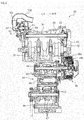
- the motorcycle 1 preferably includes the parallel three cylinder engine 20, for example.
- the parallel three cylinder engine 20 if an attempt is made to equalize the lengths of the three exhaust pipes 101 to 103, flexibility of locating the exhaust pipes 101 to 103 might be reduced, and/or the exhaust pipes 101 to 103 might be complicated in shape.
- the three exhaust pipes 101 to 103 have different lengths. According to the present preferred embodiment, it is unnecessary to equalize the lengths of the three exhaust pipes 101 to 103, thus making it possible to increase the flexibility of locating the exhaust pipes 101 to 103 and to prevent the exhaust pipes 101 to 103 from being complicated in shape.
- the three intake pipes 121 to 123 have different lengths. According to the present preferred embodiment, it is unnecessary to equalize the lengths of the three intake pipes 121 to 123, thus making it possible to set the length of each of the intake pipes 121 to 123 without being restricted by the lengths of the other intake pipes.
- the second intake pipe 122 that is the shortest of the three intake pipes 121 to 123 is in communication with the second cylinder 32 with which the second exhaust pipe 102 that is the longest of the three exhaust pipes 101 to 103 is in communication.
- the third intake pipe 123 that is the longest of the three intake pipes 121 to 123 is in communication with the third cylinder 33 with which the third exhaust pipe 103 that is the shortest of the three exhaust pipes 101 to 103 is in communication. Consequently, it is possible to suitably reduce combustion variations between the cylinders 31 to 33 without performing complicated control.
- the second exhaust pipe 102 which is the longest of the three exhaust pipes 101 to 103, is in communication with the second cylinder 32, i.e., the center one of the three cylinders 31 to 33.
- the second exhaust pipe 102 which is the longest of the three exhaust pipes 101 to 103, is centrally disposed, thus making it easy to suitably dispose the exhaust pipes 101 to 103 so that interference therebetween is prevented.
- the first, second, and third intake pipes 121, 122 and 123 have different lengths but are connected to the same air cleaner 59.
- the first, second, and third intake pipes 121, 122, and 123 are inserted into the air cleaner 59 through the insertion openings 59d.
- the opening end 121a of the first intake pipe 121, the opening end 122a of the second intake pipe 122, and the opening end 123a of the third intake pipe 123 are disposed inside the air cleaner 59. As illustrated in FIG.
- the length L1 between the opening end 121a and the insertion opening 59d, the length L2 between the opening end 122a and the insertion opening 59d, and the length L3 between the opening end 123a and the insertion opening 59d are different from each other.
- the portions of the intake pipes 121 to 123 which are disposed inside of the air cleaner 59 have different lengths, and therefore, the portions of the intake pipes 121 to 123 which are located outside of the air cleaner 59 do not need to have different lengths.
- the flexibility of locating the intake pipes 121 to 123 is increased.
- the length L2 between the opening end 122a and the insertion opening 59d is shorter than the length L1 between the opening end 121a and the insertion opening 59d and is also shorter than the length L3 between the opening end 123a and the insertion opening 59d.
- the portion 122B of the centrally-disposed second intake pipe 122 located inside of the air cleaner 59 is shorter than the portion 121B of the first intake pipe 121 located inside of the air cleaner 59 and is also shorter than the portion 123B of the third intake pipe 123 located inside of the air cleaner 59. Therefore, as illustrated in FIG. 9 , a concave 59Dm may be provided in the center of the air cleaner case 59D.
- the rider of the motorcycle 1 may lean forward in order to reduce air resistance received by his or her body.
- the air cleaner 59 is disposed forward of the seat 11, the rider is allowed to lean forward easily by providing the concave 59Dm in the air cleaner case 59D.
- the engine 20 preferably includes the exhaust manifold 68 to which the three exhaust pipes 101 to 103 are connected.
- the exhaust manifold 68 is disposed below the crankcase 22, and therefore, an overall lateral length of the engine 20 and the exhaust manifold 68 is shorter than when the exhaust manifold 68 is disposed rightward or leftward of the crankcase 22. As a result, slimming of the motorcycle 1 including the parallel three cylinder engine 20 is facilitated.
- the left and right in FIG. 3 correspond to the right and left in the front view of the vehicle.
- the first cylinder 31 is disposed rightward of the vehicle center line CL in the front view of the vehicle
- the third cylinder 33 is disposed leftward of the vehicle center line CL in the front view of the vehicle.
- the exhaust manifold 68 is disposed leftward of the vehicle center line CL in the front view of the vehicle.
- the exhaust manifold 68 is easily disposed so as to be deviated to the left.
- the exhaust manifold 68 may be disposed rightward of the vehicle center line CL in the front view of the vehicle.
- the exhaust manifold 68 is disposed leftward of the vehicle center line CL, and the three exhaust pipes 101 to 103 preferably include portions located rightward of the axes 31c to 33c of the cylinders 31 to 33 with which the exhaust pipes 101 to 103 are in communication, respectively.
- the exhaust pipes 101 to 103 each have such a shape so as to extend rightward and then extend leftward in the front view of the vehicle. Therefore, the lengths of the exhaust pipes 101 to 103 are sufficiently ensured within a small space around the crankcase 22, the cylinder body 24, and the cylinder head 26. As a result, the exhaust pipes 101 to 103 are compactly disposed while the original performance of the engine 20 is maintained.
- the exhaust manifold 68 may be disposed rightward of the vehicle center line CL, and the three exhaust pipes 101 to 103 may include portions located leftward of the axes 31c to 33c of the cylinders 31 to 33 with which the exhaust pipes 101 to 103 are in communication, respectively. Also in that case, the exhaust pipes 101 to 103 are compactly disposed while the original performance of the engine 20 is maintained.
- the second exhaust pipe 102 preferably includes a portion that overlaps with the axis 31c of the first cylinder 31 with which the adjacent first exhaust pipe 101 is in communication.
- the third exhaust pipe 103 preferably includes a portion that overlaps with the axis 32c of the second cylinder 32 with which the adjacent second exhaust pipe 102 is in communication.
- the exhaust pipes 101 to 103 preferably include the connections 101E to 103E connected to the exhaust manifold 68, respectively.
- the connection 102E of the second exhaust pipe 102 that is the longest of the exhaust pipes 101 to 103 is disposed below the connection 101E of the exhaust pipe 101 and the connection 103E of the exhaust pipe 103.
- the exhaust pipes 101 to 103 are not restricted to being equal in length, and therefore, the connections 101E to 103E of the exhaust pipes 101 to 103 can be easily disposed at such positions.
- the lateral length of the exhaust manifold 68 is shorter than when the connections 101E to 103E of the three exhaust pipes 101 to 103 are arranged in alignment with each other in the lateral direction of the motorcycle 1.
- the first exhaust pipe 101 and the second exhaust pipe 102 are connected to each other through the first connection pipe 105, and the second exhaust pipe 102 and the third exhaust pipe 103 are connected to each other through the second connection pipe 106.
- pressure fluctuations in exhaust gas inside the first, second, and third exhaust pipes 101, 102, and 103 are reduced, and therefore, fluctuations in output torque of the engine 20 are reduced.
- the connections of the first connection pipe 105 may be located at any appropriate positions.
- the first connection 105a of the first connection pipe 105 is connected to the portion of the first exhaust pipe 101 which is located upstream of the midpoint position of the first exhaust pipe 101
- the second connection 105b of the first connection pipe 105 is connected to the portion of the second exhaust pipe 102 which is located upstream of the midpoint position of the second exhaust pipe 102.
- the connections of the second connection pipe 106 may be located at any appropriate positions.
- the first connection 106a of the second connection pipe 106 is connected to the portion of the second exhaust pipe 102 which is located upstream of the midpoint position of the second exhaust pipe 102
- the second connection 106b of the second connection pipe 106 is connected to the portion of the third exhaust pipe 103 which is located upstream of the midpoint position of the third exhaust pipe 103.
- the term "intake pipes” refers to air passages between the throttle bodies 53 and the opening ends 121a to 123a inside the air cleaner 59.
- the intake pipes 121 to 123 are each preferably provided by a single pipe member, for example.
- one or two or more of the intake pipes 121 to 123 may be provided by a plurality of pipe members.
- exhaust pipes refers to exhaust gas passages between the exhaust pipe connection ports 97 of the cylinder head 26 and the exhaust manifold 68.
- the exhaust pipes 101 to 103 are each preferably provided by a single pipe member, for example Alternatively, one or two or more of the exhaust pipes 101 to 103 may be provided by a plurality of pipe members.
- the air cleaner case 59D is provided with the three separate insertion openings 59d, and thus the three insertion openings 59d into which the intake pipes 121 to 123 are inserted are independent of one another.
- the two or three insertion openings 59d may be provided continuously.
- the three insertion openings 59d into which the intake pipes 121 to 123 are inserted may be continuous with each other, so that the air cleaner case 59D is apparently provided with a single opening.
- the three insertion openings 59d may be combined into a single opening.
- the three insertion openings 59d exist so long as the three intake pipes 121 to 123 are inserted thereinto.
- the three insertion openings 59d are preferably arranged in the lateral direction of the motorcycle 1.
- the locations of the three insertion openings 59d are not limited to any particular locations.
- one of the insertion openings 59d may be located above or below the other insertion openings 59d.
- the straddle-type vehicle is a "street" motorcycle 1.
- the straddle-type vehicle may be any other type of motorcycle other than a street motorcycle.
- the term "straddle-type vehicle” refers to a vehicle that a rider straddles when getting on the vehicle.
- the straddle-type vehicle is not limited to the motorcycle 1, but may be any other vehicle such as an ROV (Recreational Off-Highway Vehicle), for example.
- the engine 20 is not limited to a water-cooled engine, but may be an air-cooled engine.
Landscapes
- Engineering & Computer Science (AREA)
- Chemical & Material Sciences (AREA)
- Combustion & Propulsion (AREA)
- Mechanical Engineering (AREA)
- General Engineering & Computer Science (AREA)
- Transportation (AREA)
- Automatic Cycles, And Cycles In General (AREA)
- Exhaust Silencers (AREA)
Claims (12)
- Ein Spreizsitz-Typ-Fahrzeug, das umfasst:eine Brennkraftmaschine (20) mit innerer Verbrennung, die beinhaltet:einen ersten Zylinder (31);einen zweiten Zylinder (32), positioniert links von dem ersten Zylinder (31) in einer Vorder-Ansicht des Fahrzeugs;einen dritten Zylinder (33), positioniert links von dem zweiten Zylinder (32) in der Vorder-Ansicht des Fahrzeugs;eine erste Abgasleitung (101) in Verbindung mit dem ersten Zylinder (31);eine zweite Abgasleitung (102) in Verbindung mit dem zweiten Zylinder (32); undeine dritte Abgasleitung (103) in Verbindung mit dem dritten Zylinder (33),gekennzeichnet durcheine erste Einlassleitung (121) in Verbindung mit dem ersten Zylinder (31);eine zweite Einlassleitung (122) in Verbindung mit dem zweiten Zylinder (32);eine dritte Einlassleitung (123) in Verbindung mit dem dritten Zylinder (33), wobei jede von den ersten, zweiten und dritten Abgasleitungen (101, 102, 103) unterschiedliche Längen haben, und jede von den ersten, zweiten und dritten Einlassleitungen (121, 122, 123) unterschiedliche Längen haben, wobei eine kürzeste von den ersten, zweiten und dritten Einlassleitungen (121, 122, 123) in Verbindung mit einem Zylinder ist, mit dem eine längste der ersten, zweiten und dritten Abgasleitungen (101, 102, 103) in Verbindung ist; undeine längste von den ersten, zweiten und dritten Einlassleitungen (121, 122, 123) ist in Verbindung mit einem Zylinder, mit dem eine kürzeste der ersten, zweiten unddritten Abgasleitungen (101, 102, 103) in Verbindung ist.
- Ein Spreizsitz-Typ-Fahrzeug gemäß Anspruch 1, dadurch gekennzeichnet, dass die längste der ersten, zweiten und dritten Abgasleitungen (101, 102, 103) die zweite Abgasleitung (102) ist.
- Ein Spreizsitz-Typ-Fahrzeug gemäß Anspruch 1 oder 2, gekennzeichnet durch einen Luftfilter (59), verbunden mit den ersten, zweiten und dritten Einlassleitungen (121, 122, 123).
- Ein Spreizsitz-Typ-Fahrzeug gemäß Anspruch 3, dadurch gekennzeichnet, dass der Luftfilter (59) beinhaltet:eine erste Einsatzöffnung (59d), in welche die erste Einlassleitung (121) eingesetzt ist;eine zweite Einsatzöffnung (59d), in welche die zweite Einlassleitung (122) eingesetzt ist; undeine dritte Einsatzöffnung (59d), in welche die dritte Einlassleitung (123) eingesetzt ist; wobei die erste Einlassleitung (121) ein erstes offenes Ende (121a) beinhaltet,positioniert in dem Luftfilter (59);die zweite Einlassleitung (122) ein zweites offenes Ende (122a) beinhaltet,positioniert in dem Luftfilter (59);die dritte Einlassleitung (123) ein drittes offenes Ende (123a) beinhaltet, positioniert in dem Luftfilter (59); undeine Länge der ersten Einlassleitung (121) von der ersten Einsatzöffnung (59d) zu dem ersten offenen Ende (121 a), eine Länge von der zweiten Einlassleitung (122) von der zweiten Einsatzöffnung (59d) zu dem zweiten offenen Ende (122a), und eine Länge von der dritten Einlassleitung (123) von der dritten Einsatzöffnung (59d) zu dem dritten offenen Ende (123a) unterschiedlich voneinander sind.
- Ein Spreizsitz-Typ-Fahrzeug gemäß irgendeinem der Ansprüche 1 bis 4, dadurch gekennzeichnet, dass die Brennkraftmaschine (20) weiterhin beinhaltet:ein Kurbelgehäuse (22);einen Zylinderkörper (24), der die ersten, zweiten und dritten Zylinder (31, 32, 33) aufnimmt, und mit dem Kurbelgehäuse (22) verbunden ist; undeinen Zylinderkopf (26), mit dem die ersten, zweiten und dritten Einlassleitungen (121, 122, 123) und die ersten, zweiten und dritten Abgasleitungen (101, 102, 103) verbunden sind, der Zylinderkopf (26) ist mit dem Zylinderkörper (24) verbunden, wobei das Spreizsitz-Typ-Fahrzeug weiterhin einen Abgasverteiler (68) umfasst, der unterhalb des Kurbelgehäuses (22) positioniert ist und mit dem die ersten, zweiten und dritten Abgasleitungen (101, 102, 103) verbunden sind.
- Ein Spreizsitz-Typ-Fahrzeug gemäß Anspruch 5, dadurch gekennzeichnet, dass der erste Zylinder (31) rechts von einer Fahrzeug-Mittellinie (CL) in der Vorder-Ansicht des Fahrzeugs positioniert ist;
der dritte Zylinder (33) links von der Fahrzeug-Mittellinie (CL) in der Vorder-Ansicht des Fahrzeugs positioniert ist; und
der Abgasverteiler (68) rechts oder links von der Fahrzeug-Mittellinie (CL) in der Vorder-Ansicht des Fahrzeugs positioniert ist. - Ein Spreizsitz-Typ-Fahrzeug gemäß Anspruch 6, dadurch gekennzeichnet, dass wenn eines von einem rechten Ende und einem linken Ende in der Vorder-Ansicht des Fahrzeugs als ein erstes Ende definiert ist, und das andere Ende als ein zweites Ende definiert ist, ist der Abgasverteiler (68) näher zu dem ersten Ende als zu der Fahrzeug-Mittellinie (CL) positioniert, die erste Abgasleitung (101) beinhaltet einen Abschnitt, angeordnet näher zu dem zweiten Ende als zu einer Achse des ersten Zylinders (31), die zweite Abgasleitung (102) beinhaltet einen Abschnitt, angeordnet näher zu dem zweiten Ende, als zu einer Achse des zweiten Zylinders (32), und die dritte Abgasleitung (103) beinhaltet einen Abschnitt, angeordnet näher zu dem zweiten Ende als zu einer Achse des dritten Zylinders (33).
- Ein Spreizsitz-Typ-Fahrzeug gemäß irgendeinem der Ansprüche 5 bis 7, dadurch gekennzeichnet, dass jede, die ersten, zweiten und dritten Abgasleitungen (101, 102, 103) eine Verbindung beinhaltet, die mit dem Abgasverteiler (68) verbunden ist; und
die Verbindung einer längsten von den ersten, zweiten und dritten Abgasleitungen (101, 102, 103) ist unterhalb der Verbindungen der anderen zwei Abgasleitungen positioniert. - Ein Spreizsitz-Typ-Fahrzeug gemäß irgendeinem der Ansprüche 1 bis 8, dadurch gekennzeichnet, dass in der Vorder-Ansicht des Fahrzeugs, zumindest eine von den ersten, zweiten und dritten Abgasleitungen (101, 102, 103) einen Abschnitt beinhaltet, der mit einer Achse eines Zylinders überlappt, mit dem eine benachbarte Abgasleitung in Verbindung ist.
- Ein Spreizsitz-Typ-Fahrzeug gemäß irgendeinem der Ansprüche 1 bis 9,
gekennzeichnet durch:einer ersten Verbindungsleitung (105), verbunden mit der ersten Abgasleitung (101) und der zweiten Abgasleitung (102); undeiner zweiten Verbindungsleitung (106), verbunden mit der zweiten Abgasleitung (102) und der dritten Abgasleitung (103). - Ein Spreizsitz-Typ-Fahrzeug gemäß Anspruch 10, dadurch gekennzeichnet, dass die erste Verbindungsleitung (105) beinhaltet:eine erste Verbindung (105a), verbunden mit einem Abschnitt der ersten Abgasleitung (101), der stromauf von einer Mittelpunktposition der ersten Abgasleitung (101) angeordnet ist; undeine zweite Verbindung (105b), verbunden mit einem Abschnitt von der zweiten Abgasleitung (102), der stromauf von einer Mittelpunktposition der zweiten Abgasleitung (102) angeordnet ist, wobeidie zweite Verbindungsleitung (106) beinhaltet:eine erste Verbindung (106a), verbunden mit einem Abschnitt der zweiten Abgasleitung (102), der stromauf von der Mittelpunktposition in einer Längsrichtung der zweiten Abgasleitung (102) angeordnet ist; undeine zweiten Verbindung (106b), verbunden mit einem Abschnitt der dritten Abgasleitung (103), die stromauf von einer Mittelpunktposition in einer Längsrichtung der dritten Abgasleitung (103) angeordnet ist.
- Ein Spreizsitz-Typ-Fahrzeug gemäß irgendeinem der Ansprüche 1 bis 11, dadurch gekennzeichnet, dass das Spreizsitz-Typ-Fahrzeug ein Motorrad ist.
Applications Claiming Priority (1)
| Application Number | Priority Date | Filing Date | Title |
|---|---|---|---|
| JP2013108645A JP2014227927A (ja) | 2013-05-23 | 2013-05-23 | 鞍乗型車両 |
Publications (2)
| Publication Number | Publication Date |
|---|---|
| EP2805878A1 EP2805878A1 (de) | 2014-11-26 |
| EP2805878B1 true EP2805878B1 (de) | 2016-05-25 |
Family
ID=50289548
Family Applications (1)
| Application Number | Title | Priority Date | Filing Date |
|---|---|---|---|
| EP14160671.5A Active EP2805878B1 (de) | 2013-05-23 | 2014-03-19 | Grätschsitz-Fahrzeug |
Country Status (4)
| Country | Link |
|---|---|
| US (1) | US9103278B2 (de) |
| EP (1) | EP2805878B1 (de) |
| JP (1) | JP2014227927A (de) |
| ES (1) | ES2574643T3 (de) |
Families Citing this family (4)
| Publication number | Priority date | Publication date | Assignee | Title |
|---|---|---|---|---|
| JP6298301B2 (ja) * | 2013-03-30 | 2018-03-20 | 本田技研工業株式会社 | 内燃機関の排気管構造 |
| JP2017120026A (ja) * | 2015-12-28 | 2017-07-06 | 川崎重工業株式会社 | 車両の排気装置 |
| JP6704300B2 (ja) * | 2016-06-15 | 2020-06-03 | 川崎重工業株式会社 | 自動二輪車 |
| JP7307656B2 (ja) * | 2019-10-18 | 2023-07-12 | カワサキモータース株式会社 | エンジンの吸気装置 |
Family Cites Families (25)
| Publication number | Priority date | Publication date | Assignee | Title |
|---|---|---|---|---|
| DE2525769C3 (de) * | 1975-06-10 | 1980-11-27 | Maschinenfabrik Augsburg-Nuernberg Ag, 8500 Nuernberg | Freisaugende Achtzylinder-Dieselbrennkraftmaschine |
| DE2544813A1 (de) * | 1975-10-07 | 1977-04-14 | Elsbett L | Brennkraftmaschine, insbesondere dieselmotor |
| US4437306A (en) * | 1981-11-25 | 1984-03-20 | Honda Giken Kogyo Kabushiki Kaisha | Exhaust gas cleaning device of internal combustion engine |
| US4890586A (en) * | 1986-08-06 | 1990-01-02 | Honda Giken Kogyo Kabushiki Kaisha | Intake device for an internal combustion engine |
| EP0317093B1 (de) * | 1987-10-27 | 1993-01-27 | Suzuki Kabushiki Kaisha | Für einen Motorradmotor angepasstes Lufteinlasssystem |
| JPH0953458A (ja) * | 1995-05-30 | 1997-02-25 | Yamaha Motor Co Ltd | 燃料噴射式多気筒内燃機関 |
| US5946908A (en) * | 1996-01-17 | 1999-09-07 | Yamaha Hatsudoki Kabushiki Kaisha | Engine control and wall temperature sensor |
| IT250475Y1 (it) * | 2000-11-16 | 2003-09-10 | Ducati Motor Holding Spa | Impianto di scarico di un motore pluricilindrico per motocicletta |
| DE60103277D1 (de) * | 2001-09-14 | 2004-06-17 | Ducati Motor Holding Spa | Vorrichtung zum Mischen von Luft und Brennstoff für eine Brennkraftmaschine |
| JP4340500B2 (ja) * | 2003-09-09 | 2009-10-07 | 川崎重工業株式会社 | 自動二輪車の吸気装置 |
| EP1803909B2 (de) * | 2003-12-01 | 2018-07-04 | Nissan Motor Co., Ltd. | Abgaskrümmer für einen Verbrennungsmotor |
| JP4500198B2 (ja) * | 2004-04-22 | 2010-07-14 | 株式会社ケーヒン | 自動二輪車 |
| US6901898B1 (en) * | 2004-04-26 | 2005-06-07 | Toyota Technical Center Usa, Inc. | Variable runner length intake manifold |
| JP4455962B2 (ja) * | 2004-09-13 | 2010-04-21 | 川崎重工業株式会社 | 自動二輪車の排気装置 |
| JP4392315B2 (ja) * | 2004-09-30 | 2009-12-24 | 本田技研工業株式会社 | 自動二輪車における空燃比センサの配置構造 |
| JP2007008442A (ja) * | 2005-03-11 | 2007-01-18 | Yamaha Motor Co Ltd | 自動二輪車の排気装置 |
| JP4546310B2 (ja) * | 2005-03-31 | 2010-09-15 | 川崎重工業株式会社 | 自動二輪車用エンジンの排気システム |
| JP2007083849A (ja) | 2005-09-21 | 2007-04-05 | Honda Motor Co Ltd | 低床式の自動二輪車 |
| EP1767446B1 (de) * | 2005-09-21 | 2015-07-15 | Honda Motor Co., Ltd. | Niederflurfahrrad |
| DE102006044875B4 (de) * | 2005-09-30 | 2012-12-20 | Honda Motor Co., Ltd. | Abgassystem für ein Motorrad |
| JP4767183B2 (ja) * | 2007-01-15 | 2011-09-07 | 川崎重工業株式会社 | エンジンの排気デバイス |
| JP4901554B2 (ja) * | 2007-03-30 | 2012-03-21 | 本田技研工業株式会社 | 自動2輪車の排気装置 |
| JP4700041B2 (ja) * | 2007-11-02 | 2011-06-15 | 本田技研工業株式会社 | 自動二輪車の排気装置 |
| JP2011196242A (ja) * | 2010-03-19 | 2011-10-06 | Kawasaki Heavy Ind Ltd | 自動二輪車の排気チャンバ |
| US9273643B2 (en) * | 2012-08-10 | 2016-03-01 | Tula Technology, Inc. | Control of manifold vacuum in skip fire operation |
-
2013
- 2013-05-23 JP JP2013108645A patent/JP2014227927A/ja active Pending
-
2014
- 2014-03-19 ES ES14160671.5T patent/ES2574643T3/es active Active
- 2014-03-19 EP EP14160671.5A patent/EP2805878B1/de active Active
- 2014-04-01 US US14/231,986 patent/US9103278B2/en active Active
Also Published As
| Publication number | Publication date |
|---|---|
| ES2574643T3 (es) | 2016-06-21 |
| EP2805878A1 (de) | 2014-11-26 |
| US20140345259A1 (en) | 2014-11-27 |
| US9103278B2 (en) | 2015-08-11 |
| JP2014227927A (ja) | 2014-12-08 |
Similar Documents
| Publication | Publication Date | Title |
|---|---|---|
| US9279360B2 (en) | Cooling apparatus for internal combustion engine and motorcycle including the same | |
| US7434561B2 (en) | Engine | |
| US9266421B2 (en) | Cooling system structure for vehicular water-cooled internal combustion engine | |
| US9938881B2 (en) | Cooling water passage structure of internal combustion engine | |
| JP2017082648A (ja) | 鞍乗型車両 | |
| EP2805878A1 (de) | Grätschsitz-Fahrzeug | |
| JP2007262930A (ja) | 小型車両用内燃機関 | |
| JP5865154B2 (ja) | 車両用水冷式内燃機関の冷却系構造 | |
| JP5798427B2 (ja) | 空油冷内燃機関のオイル通路構造 | |
| JP6347150B2 (ja) | 自動二輪車のエンジン冷却装置 | |
| US9200549B2 (en) | Internal combustion engine and motorcycle equipped with the engine | |
| JP5048618B2 (ja) | 4サイクル空油冷エンジン | |
| US8925512B2 (en) | Support structure for water-cooled internal combustion engine | |
| US9988978B2 (en) | Four-cycle multi-cylinder engine | |
| US8960684B2 (en) | Internal combustion engine having positioning pins disposed within fluid communication ports | |
| EP2806133B1 (de) | Motorrad | |
| EP2806135B1 (de) | Kühlvorrichtung für Verbrennungsmotor und Motorrad damit | |
| JP6248534B2 (ja) | 過給機付自動二輪車 | |
| JP4084480B2 (ja) | 車両用v型内燃機関 | |
| JP7428594B2 (ja) | エンジンユニット | |
| JP2007262931A (ja) | 内燃機関の冷却水配管構造 | |
| JP4892531B2 (ja) | 車両用エンジンにおける冷却用オイル通路構造 | |
| JP4914877B2 (ja) | エンジンの冷却用オイル通路構造 | |
| JP4990249B2 (ja) | 4サイクル空油冷エンジン |
Legal Events
| Date | Code | Title | Description |
|---|---|---|---|
| PUAI | Public reference made under article 153(3) epc to a published international application that has entered the european phase |
Free format text: ORIGINAL CODE: 0009012 |
|
| 17P | Request for examination filed |
Effective date: 20140319 |
|
| AK | Designated contracting states |
Kind code of ref document: A1 Designated state(s): AL AT BE BG CH CY CZ DE DK EE ES FI FR GB GR HR HU IE IS IT LI LT LU LV MC MK MT NL NO PL PT RO RS SE SI SK SM TR |
|
| AX | Request for extension of the european patent |
Extension state: BA ME |
|
| RIN1 | Information on inventor provided before grant (corrected) |
Inventor name: KAWASE, MASAHITO Inventor name: OOISHI, KATSUYOSHI Inventor name: HAMADA, DAISUKE Inventor name: FUJIMURA, KATSUMI Inventor name: YOSHIDA, YASUTAKA |
|
| R17P | Request for examination filed (corrected) |
Effective date: 20150217 |
|
| RBV | Designated contracting states (corrected) |
Designated state(s): AL AT BE BG CH CY CZ DE DK EE ES FI FR GB GR HR HU IE IS IT LI LT LU LV MC MK MT NL NO PL PT RO RS SE SI SK SM TR |
|
| 17Q | First examination report despatched |
Effective date: 20150603 |
|
| GRAP | Despatch of communication of intention to grant a patent |
Free format text: ORIGINAL CODE: EPIDOSNIGR1 |
|
| INTG | Intention to grant announced |
Effective date: 20160202 |
|
| GRAS | Grant fee paid |
Free format text: ORIGINAL CODE: EPIDOSNIGR3 |
|
| GRAA | (expected) grant |
Free format text: ORIGINAL CODE: 0009210 |
|
| AK | Designated contracting states |
Kind code of ref document: B1 Designated state(s): AL AT BE BG CH CY CZ DE DK EE ES FI FR GB GR HR HU IE IS IT LI LT LU LV MC MK MT NL NO PL PT RO RS SE SI SK SM TR |
|
| REG | Reference to a national code |
Ref country code: GB Ref legal event code: FG4D |
|
| REG | Reference to a national code |
Ref country code: CH Ref legal event code: EP |
|
| REG | Reference to a national code |
Ref country code: IE Ref legal event code: FG4D Ref country code: AT Ref legal event code: REF Ref document number: 802057 Country of ref document: AT Kind code of ref document: T Effective date: 20160615 |
|
| REG | Reference to a national code |
Ref country code: ES Ref legal event code: FG2A Ref document number: 2574643 Country of ref document: ES Kind code of ref document: T3 Effective date: 20160621 |
|
| REG | Reference to a national code |
Ref country code: DE Ref legal event code: R096 Ref document number: 602014002030 Country of ref document: DE |
|
| REG | Reference to a national code |
Ref country code: LT Ref legal event code: MG4D |
|
| REG | Reference to a national code |
Ref country code: NL Ref legal event code: MP Effective date: 20160525 |
|
| PG25 | Lapsed in a contracting state [announced via postgrant information from national office to epo] |
Ref country code: FI Free format text: LAPSE BECAUSE OF FAILURE TO SUBMIT A TRANSLATION OF THE DESCRIPTION OR TO PAY THE FEE WITHIN THE PRESCRIBED TIME-LIMIT Effective date: 20160525 Ref country code: NO Free format text: LAPSE BECAUSE OF FAILURE TO SUBMIT A TRANSLATION OF THE DESCRIPTION OR TO PAY THE FEE WITHIN THE PRESCRIBED TIME-LIMIT Effective date: 20160825 Ref country code: NL Free format text: LAPSE BECAUSE OF FAILURE TO SUBMIT A TRANSLATION OF THE DESCRIPTION OR TO PAY THE FEE WITHIN THE PRESCRIBED TIME-LIMIT Effective date: 20160525 Ref country code: LT Free format text: LAPSE BECAUSE OF FAILURE TO SUBMIT A TRANSLATION OF THE DESCRIPTION OR TO PAY THE FEE WITHIN THE PRESCRIBED TIME-LIMIT Effective date: 20160525 |
|
| REG | Reference to a national code |
Ref country code: AT Ref legal event code: MK05 Ref document number: 802057 Country of ref document: AT Kind code of ref document: T Effective date: 20160525 |
|
| PG25 | Lapsed in a contracting state [announced via postgrant information from national office to epo] |
Ref country code: PT Free format text: LAPSE BECAUSE OF FAILURE TO SUBMIT A TRANSLATION OF THE DESCRIPTION OR TO PAY THE FEE WITHIN THE PRESCRIBED TIME-LIMIT Effective date: 20160926 Ref country code: LV Free format text: LAPSE BECAUSE OF FAILURE TO SUBMIT A TRANSLATION OF THE DESCRIPTION OR TO PAY THE FEE WITHIN THE PRESCRIBED TIME-LIMIT Effective date: 20160525 Ref country code: GR Free format text: LAPSE BECAUSE OF FAILURE TO SUBMIT A TRANSLATION OF THE DESCRIPTION OR TO PAY THE FEE WITHIN THE PRESCRIBED TIME-LIMIT Effective date: 20160826 Ref country code: SE Free format text: LAPSE BECAUSE OF FAILURE TO SUBMIT A TRANSLATION OF THE DESCRIPTION OR TO PAY THE FEE WITHIN THE PRESCRIBED TIME-LIMIT Effective date: 20160525 Ref country code: RS Free format text: LAPSE BECAUSE OF FAILURE TO SUBMIT A TRANSLATION OF THE DESCRIPTION OR TO PAY THE FEE WITHIN THE PRESCRIBED TIME-LIMIT Effective date: 20160525 |
|
| PG25 | Lapsed in a contracting state [announced via postgrant information from national office to epo] |
Ref country code: CZ Free format text: LAPSE BECAUSE OF FAILURE TO SUBMIT A TRANSLATION OF THE DESCRIPTION OR TO PAY THE FEE WITHIN THE PRESCRIBED TIME-LIMIT Effective date: 20160525 Ref country code: RO Free format text: LAPSE BECAUSE OF FAILURE TO SUBMIT A TRANSLATION OF THE DESCRIPTION OR TO PAY THE FEE WITHIN THE PRESCRIBED TIME-LIMIT Effective date: 20160525 Ref country code: DK Free format text: LAPSE BECAUSE OF FAILURE TO SUBMIT A TRANSLATION OF THE DESCRIPTION OR TO PAY THE FEE WITHIN THE PRESCRIBED TIME-LIMIT Effective date: 20160525 Ref country code: EE Free format text: LAPSE BECAUSE OF FAILURE TO SUBMIT A TRANSLATION OF THE DESCRIPTION OR TO PAY THE FEE WITHIN THE PRESCRIBED TIME-LIMIT Effective date: 20160525 Ref country code: SK Free format text: LAPSE BECAUSE OF FAILURE TO SUBMIT A TRANSLATION OF THE DESCRIPTION OR TO PAY THE FEE WITHIN THE PRESCRIBED TIME-LIMIT Effective date: 20160525 |
|
| PG25 | Lapsed in a contracting state [announced via postgrant information from national office to epo] |
Ref country code: BE Free format text: LAPSE BECAUSE OF FAILURE TO SUBMIT A TRANSLATION OF THE DESCRIPTION OR TO PAY THE FEE WITHIN THE PRESCRIBED TIME-LIMIT Effective date: 20160525 Ref country code: SM Free format text: LAPSE BECAUSE OF FAILURE TO SUBMIT A TRANSLATION OF THE DESCRIPTION OR TO PAY THE FEE WITHIN THE PRESCRIBED TIME-LIMIT Effective date: 20160525 Ref country code: PL Free format text: LAPSE BECAUSE OF FAILURE TO SUBMIT A TRANSLATION OF THE DESCRIPTION OR TO PAY THE FEE WITHIN THE PRESCRIBED TIME-LIMIT Effective date: 20160525 Ref country code: AT Free format text: LAPSE BECAUSE OF FAILURE TO SUBMIT A TRANSLATION OF THE DESCRIPTION OR TO PAY THE FEE WITHIN THE PRESCRIBED TIME-LIMIT Effective date: 20160525 |
|
| REG | Reference to a national code |
Ref country code: DE Ref legal event code: R097 Ref document number: 602014002030 Country of ref document: DE |
|
| REG | Reference to a national code |
Ref country code: FR Ref legal event code: PLFP Year of fee payment: 4 |
|
| PLBE | No opposition filed within time limit |
Free format text: ORIGINAL CODE: 0009261 |
|
| STAA | Information on the status of an ep patent application or granted ep patent |
Free format text: STATUS: NO OPPOSITION FILED WITHIN TIME LIMIT |
|
| 26N | No opposition filed |
Effective date: 20170228 |
|
| PG25 | Lapsed in a contracting state [announced via postgrant information from national office to epo] |
Ref country code: SI Free format text: LAPSE BECAUSE OF FAILURE TO SUBMIT A TRANSLATION OF THE DESCRIPTION OR TO PAY THE FEE WITHIN THE PRESCRIBED TIME-LIMIT Effective date: 20160525 |
|
| REG | Reference to a national code |
Ref country code: CH Ref legal event code: PL |
|
| PG25 | Lapsed in a contracting state [announced via postgrant information from national office to epo] |
Ref country code: MC Free format text: LAPSE BECAUSE OF FAILURE TO SUBMIT A TRANSLATION OF THE DESCRIPTION OR TO PAY THE FEE WITHIN THE PRESCRIBED TIME-LIMIT Effective date: 20160525 |
|
| REG | Reference to a national code |
Ref country code: IE Ref legal event code: MM4A |
|
| PG25 | Lapsed in a contracting state [announced via postgrant information from national office to epo] |
Ref country code: LU Free format text: LAPSE BECAUSE OF NON-PAYMENT OF DUE FEES Effective date: 20170319 |
|
| PG25 | Lapsed in a contracting state [announced via postgrant information from national office to epo] |
Ref country code: LI Free format text: LAPSE BECAUSE OF NON-PAYMENT OF DUE FEES Effective date: 20170331 Ref country code: CH Free format text: LAPSE BECAUSE OF NON-PAYMENT OF DUE FEES Effective date: 20170331 Ref country code: IE Free format text: LAPSE BECAUSE OF NON-PAYMENT OF DUE FEES Effective date: 20170319 |
|
| REG | Reference to a national code |
Ref country code: FR Ref legal event code: PLFP Year of fee payment: 5 |
|
| PG25 | Lapsed in a contracting state [announced via postgrant information from national office to epo] |
Ref country code: MT Free format text: LAPSE BECAUSE OF NON-PAYMENT OF DUE FEES Effective date: 20170319 |
|
| PG25 | Lapsed in a contracting state [announced via postgrant information from national office to epo] |
Ref country code: AL Free format text: LAPSE BECAUSE OF FAILURE TO SUBMIT A TRANSLATION OF THE DESCRIPTION OR TO PAY THE FEE WITHIN THE PRESCRIBED TIME-LIMIT Effective date: 20160525 |
|
| PG25 | Lapsed in a contracting state [announced via postgrant information from national office to epo] |
Ref country code: HU Free format text: LAPSE BECAUSE OF FAILURE TO SUBMIT A TRANSLATION OF THE DESCRIPTION OR TO PAY THE FEE WITHIN THE PRESCRIBED TIME-LIMIT; INVALID AB INITIO Effective date: 20140319 |
|
| PG25 | Lapsed in a contracting state [announced via postgrant information from national office to epo] |
Ref country code: BG Free format text: LAPSE BECAUSE OF FAILURE TO SUBMIT A TRANSLATION OF THE DESCRIPTION OR TO PAY THE FEE WITHIN THE PRESCRIBED TIME-LIMIT Effective date: 20160525 |
|
| PG25 | Lapsed in a contracting state [announced via postgrant information from national office to epo] |
Ref country code: CY Free format text: LAPSE BECAUSE OF FAILURE TO SUBMIT A TRANSLATION OF THE DESCRIPTION OR TO PAY THE FEE WITHIN THE PRESCRIBED TIME-LIMIT Effective date: 20160525 |
|
| PG25 | Lapsed in a contracting state [announced via postgrant information from national office to epo] |
Ref country code: MK Free format text: LAPSE BECAUSE OF FAILURE TO SUBMIT A TRANSLATION OF THE DESCRIPTION OR TO PAY THE FEE WITHIN THE PRESCRIBED TIME-LIMIT Effective date: 20160525 |
|
| PG25 | Lapsed in a contracting state [announced via postgrant information from national office to epo] |
Ref country code: TR Free format text: LAPSE BECAUSE OF FAILURE TO SUBMIT A TRANSLATION OF THE DESCRIPTION OR TO PAY THE FEE WITHIN THE PRESCRIBED TIME-LIMIT Effective date: 20160525 |
|
| PG25 | Lapsed in a contracting state [announced via postgrant information from national office to epo] |
Ref country code: HR Free format text: LAPSE BECAUSE OF FAILURE TO SUBMIT A TRANSLATION OF THE DESCRIPTION OR TO PAY THE FEE WITHIN THE PRESCRIBED TIME-LIMIT Effective date: 20160525 |
|
| PG25 | Lapsed in a contracting state [announced via postgrant information from national office to epo] |
Ref country code: IS Free format text: LAPSE BECAUSE OF FAILURE TO SUBMIT A TRANSLATION OF THE DESCRIPTION OR TO PAY THE FEE WITHIN THE PRESCRIBED TIME-LIMIT Effective date: 20160925 |
|
| P01 | Opt-out of the competence of the unified patent court (upc) registered |
Effective date: 20230527 |
|
| PGFP | Annual fee paid to national office [announced via postgrant information from national office to epo] |
Ref country code: ES Payment date: 20250429 Year of fee payment: 12 |
|
| PGFP | Annual fee paid to national office [announced via postgrant information from national office to epo] |
Ref country code: GB Payment date: 20260324 Year of fee payment: 13 |
|
| PGFP | Annual fee paid to national office [announced via postgrant information from national office to epo] |
Ref country code: DE Payment date: 20260319 Year of fee payment: 13 |
|
| PGFP | Annual fee paid to national office [announced via postgrant information from national office to epo] |
Ref country code: IT Payment date: 20260324 Year of fee payment: 13 |
|
| PGFP | Annual fee paid to national office [announced via postgrant information from national office to epo] |
Ref country code: FR Payment date: 20260320 Year of fee payment: 13 |