EP2801733A1 - Dämpfungsventil für stossdämpfer - Google Patents
Dämpfungsventil für stossdämpfer Download PDFInfo
- Publication number
- EP2801733A1 EP2801733A1 EP13762028.2A EP13762028A EP2801733A1 EP 2801733 A1 EP2801733 A1 EP 2801733A1 EP 13762028 A EP13762028 A EP 13762028A EP 2801733 A1 EP2801733 A1 EP 2801733A1
- Authority
- EP
- European Patent Office
- Prior art keywords
- retainer
- valve disk
- piston
- valve
- peripheral side
- Prior art date
- Legal status (The legal status is an assumption and is not a legal conclusion. Google has not performed a legal analysis and makes no representation as to the accuracy of the status listed.)
- Granted
Links
Images



Classifications
-
- F—MECHANICAL ENGINEERING; LIGHTING; HEATING; WEAPONS; BLASTING
- F16—ENGINEERING ELEMENTS AND UNITS; GENERAL MEASURES FOR PRODUCING AND MAINTAINING EFFECTIVE FUNCTIONING OF MACHINES OR INSTALLATIONS; THERMAL INSULATION IN GENERAL
- F16F—SPRINGS; SHOCK-ABSORBERS; MEANS FOR DAMPING VIBRATION
- F16F9/00—Springs, vibration-dampers, shock-absorbers, or similarly-constructed movement-dampers using a fluid or the equivalent as damping medium
- F16F9/32—Details
- F16F9/34—Special valve constructions; Shape or construction of throttling passages
- F16F9/348—Throttling passages in the form of annular discs or other plate-like elements which may or may not have a spring action, operating in opposite directions or singly, e.g. annular discs positioned on top of the valve or piston body
- F16F9/3484—Throttling passages in the form of annular discs or other plate-like elements which may or may not have a spring action, operating in opposite directions or singly, e.g. annular discs positioned on top of the valve or piston body characterised by features of the annular discs per se, singularly or in combination
-
- F—MECHANICAL ENGINEERING; LIGHTING; HEATING; WEAPONS; BLASTING
- F16—ENGINEERING ELEMENTS AND UNITS; GENERAL MEASURES FOR PRODUCING AND MAINTAINING EFFECTIVE FUNCTIONING OF MACHINES OR INSTALLATIONS; THERMAL INSULATION IN GENERAL
- F16F—SPRINGS; SHOCK-ABSORBERS; MEANS FOR DAMPING VIBRATION
- F16F9/00—Springs, vibration-dampers, shock-absorbers, or similarly-constructed movement-dampers using a fluid or the equivalent as damping medium
- F16F9/32—Details
- F16F9/3207—Constructional features
- F16F9/3214—Constructional features of pistons
-
- F—MECHANICAL ENGINEERING; LIGHTING; HEATING; WEAPONS; BLASTING
- F16—ENGINEERING ELEMENTS AND UNITS; GENERAL MEASURES FOR PRODUCING AND MAINTAINING EFFECTIVE FUNCTIONING OF MACHINES OR INSTALLATIONS; THERMAL INSULATION IN GENERAL
- F16F—SPRINGS; SHOCK-ABSORBERS; MEANS FOR DAMPING VIBRATION
- F16F9/00—Springs, vibration-dampers, shock-absorbers, or similarly-constructed movement-dampers using a fluid or the equivalent as damping medium
- F16F9/32—Details
- F16F9/34—Special valve constructions; Shape or construction of throttling passages
- F16F9/348—Throttling passages in the form of annular discs or other plate-like elements which may or may not have a spring action, operating in opposite directions or singly, e.g. annular discs positioned on top of the valve or piston body
- F16F9/3481—Throttling passages in the form of annular discs or other plate-like elements which may or may not have a spring action, operating in opposite directions or singly, e.g. annular discs positioned on top of the valve or piston body characterised by shape or construction of throttling passages in piston
-
- F—MECHANICAL ENGINEERING; LIGHTING; HEATING; WEAPONS; BLASTING
- F16—ENGINEERING ELEMENTS AND UNITS; GENERAL MEASURES FOR PRODUCING AND MAINTAINING EFFECTIVE FUNCTIONING OF MACHINES OR INSTALLATIONS; THERMAL INSULATION IN GENERAL
- F16K—VALVES; TAPS; COCKS; ACTUATING-FLOATS; DEVICES FOR VENTING OR AERATING
- F16K15/00—Check valves
- F16K15/14—Check valves with flexible valve members
-
- F—MECHANICAL ENGINEERING; LIGHTING; HEATING; WEAPONS; BLASTING
- F16—ENGINEERING ELEMENTS AND UNITS; GENERAL MEASURES FOR PRODUCING AND MAINTAINING EFFECTIVE FUNCTIONING OF MACHINES OR INSTALLATIONS; THERMAL INSULATION IN GENERAL
- F16F—SPRINGS; SHOCK-ABSORBERS; MEANS FOR DAMPING VIBRATION
- F16F9/00—Springs, vibration-dampers, shock-absorbers, or similarly-constructed movement-dampers using a fluid or the equivalent as damping medium
- F16F9/32—Details
- F16F9/34—Special valve constructions; Shape or construction of throttling passages
- F16F9/348—Throttling passages in the form of annular discs or other plate-like elements which may or may not have a spring action, operating in opposite directions or singly, e.g. annular discs positioned on top of the valve or piston body
Definitions
- the present invention relates to a damping valve for shock absorber.
- a damping valve for shock absorber is applied, for example, to a piston unit or the like of a shock absorber for vehicle and is provided with a piston (valve disk) partitioning one chamber and another chamber for storing working fluid in the shock absorber, a flow passage formed in this piston to allow communication between the one and the other chambers, and a damping force generating element such as a leaf valve for applying resistance to the working fluid passing in this flow passage.
- the shock absorber When the piston moves toward the one or the other chamber, the one or the other chamber is pressurized and the working fluid moves between the one and the other chambers through the flow passage. In this way, the shock absorber generates a damping force due to the resistance of the damping force generating element.
- damping valve capable of realizing various damping characteristics so that the shock absorber can realize a desired damping characteristic (change in damping force in relation to piston speed).
- JP2008-138696A discloses a damping valve for shock absorber in which a retainer is provided to be placed on a piston partitioning one chamber and another chamber.
- the above damping valve is provided with an inner peripheral side flow passage configured to include a valve disk through hole formed in an inner peripheral side of the piston and a retainer through hole formed in the retainer and allowing communication between the one and the other chambers, and an outer peripheral side flow passage formed in an outer peripheral side of the piston and allowing communication between the one and the other chambers.
- a damping coefficient (ratio of the amount of change in damping force to the amount of change in piston speed) of a valve characteristic due to resistance produced when the working fluid passes through a clearance between an outer peripheral part of the leaf valve and the valve seat can be decreased.
- a damping force characteristic can be variously changed by replaceably mounting retainers having various dimensions and shapes.
- a shock absorber to which the above damping valve is applied generates a damping force with a port characteristic due to resistance produced during the passage of the working fluid in the inner peripheral side flow passage when the leaf valve is opened to a certain extent. Further, the damping force with the port characteristic can be changed by a replacement with a retainer having a different flow passage area of a retainer through hole.
- the present invention was developed in view of the above problem and aims to provide a damping valve for shock absorber which enables a piston (valve disk) to be used in combination with a retainer and can increase a damping coefficient of a port characteristic also in the case of singly using the piston and change a damping force with a port characteristic.
- a damping valve for shock absorber includes a valve disk partitioning the interior of a cylinder into one chamber and another chamber, a retainer provided to be placed on the valve disk, an inner peripheral side flow passage configured to include a valve disk through hole formed in an inner peripheral side of the valve disk and a retainer through hole formed in the retainer and allowing communication between the one and the other chambers, an outer peripheral side flow passage formed in an outer peripheral side of the valve disk and allowing communication between the one and the other chambers, and a leaf valve in the form of an annular plate arranged on a side of the retainer opposite to the valve disk and configured to openably close the inner peripheral side flow passage by an outer peripheral part, wherein a flow passage area of the retainer through hole is not smaller than that of the valve disk through hole.
- a damping valve according to the present embodiment is applied to a piston unit of a shock absorber D and provided with a piston (valve disk) 1 partitioning one chamber A and another chamber B, a retainer 2 provided to be placed on the piston 1, an inner peripheral side flow passage 3a configured to include valve disk through holes 10 formed in an inner peripheral side of the piston 1 and retainer through holes 20 formed in the retainer 2 and allowing communication between the one chamber A and the other chamber B, outer peripheral side flow passages 3b formed in an outer peripheral side of the piston 1 and allowing communication between the one chamber A and the other chamber B, and leaf valves 4a in the form of annular plates arranged on a side of the retainer 2 opposite to the piston and configured to openably close the inner peripheral side flow passage 3a by outer peripheral parts.
- a flow passage area of the retainer through holes 20 is set to be not smaller than the flow passage area of the valve disk through holes 10.
- the shock absorber D is configured to be provided with a cylinder 5 for storing working fluid composed of liquid such as water, aqueous solution or oil, an annular head member (not shown) for sealing an one-side opening of the cylinder 5, a piston rod 6 rotatably supported on the head member and slidably penetrating through the head member, the piston 1 held on a mounting portion 60 of the piston rod 6, a sealing member (not shown) for closing an other-side opening of the cylinder 5, and a reservoir (not shown) or an air chamber (not shown) for compensating for a volumetric change in the cylinder caused by the volume of the piston rod 6 entering the cylinder 5.
- a cylinder 5 for storing working fluid composed of liquid such as water, aqueous solution or oil
- an annular head member (not shown) for sealing an one-side opening of the cylinder 5
- a piston rod 6 rotatably supported on the head member and slidably penetrating through the head member, the piston 1 held on a mounting portion 60 of the
- the interior of the cylinder 5 is partitioned by the piston 1 into the one and the other chambers A, B filled with the working fluid, and the one and the other chambers A, B communicate via the inner peripheral side flow passage 3a and the outer peripheral side flow passages 3b.
- the damping valve is described in detail below.
- a plurality of leaf valves 4b in the form of annular plates, a spacer 7 and a valve stopper 8 are laminated in this order from the piston 1 side on a side of piston (valve disk) 1 in the one chamber A.
- the retainer 2, a shim 9 in the form of an annular plate, a plurality of leaf valves 4a in the form of annular plates, and a spacer 7 are laminated in this order from the piston 1 side on a side of the piston 1 in the other chamber B.
- the mounting portion 60 having a smaller outer diameter than the piston rod 6 is formed on a tip part of the piston rod 6 holding the piston 1, and a step portion 61 is formed between parts having different outer diameters. Further, a screw groove with which a nut N is to be threadably engaged is formed on a tip part 60a of the mounting portion 60.
- leaf valves 4a, 4b are fixed to the piston rod 6, but outer peripheral sides thereof can be deflected in a direction away from the piston. Further, the leaf valves 4a laminated on the retainer 2 are initially deflected, and this deflection amount can be adjusted by using a shim 9 having a different thickness or changing the number of laminated shims 9.
- the piston 1 is provided with a piston main body 1b formed into an annular shape by including a mounting hole 1a though which the mounting portion 60 of the piston rod 6 penetrates, and a slide contact portion 1c which is mounted along the outer periphery of the piston main body 1b and slides in contact with the inner peripheral surface of the cylinder 5. Further, an outer peripheral part of the piston main body 1b extends toward the retainer 2, thereby forming a tubular skirt portion 1d.
- the outer peripheral side flow passages 3b allowing communication between the one and the other chambers A, B are formed in an outer peripheral side of the piston main body 1b and at an inner side of the skirt portion 1d, and the exits of the outer peripheral side flow passages 3b are openably closed by the leaf valves 4b.
- the inner peripheral side flow passage 3a is formed in an inner peripheral side of the piston main body 1b and the retainer 2 and the exit of the inner peripheral side flow passage 3a is openably closed by the leaf valves 4a.
- cuts 40 which function as orifices are respectively formed on outer peripheral parts of the leaf valves 4a, 4b located closest to the piston 1 (retainer 2).
- the outer peripheral side flow passage 3b penetrates through the piston 1 in a direction of a central axis of the shock absorber D and a plurality of the outer peripheral side flow passages 3b are formed along a circumferential direction in the outer peripheral side of the piston 1.
- the inner peripheral side flow passage 3a is configured to include a plurality of valve disk through holes 10 penetrating through the piston 1 in the direction of the central axis of the shock absorber D and formed along the circumferential direction in the inner peripheral side of the piston 1 and a plurality of retainer through holes 20 penetrating through the retainer 2 in the direction of the central axis of the shock absorber D and formed along a circumferential direction of the retainer 2.
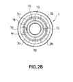
- windows 11 continuous with the respective outer peripheral side flow passages 3b and windows 12 continuous with the respective valve disk through holes 10 are alternately formed in the circumferential direction on a surface of the piston 1 opposite to the retainer 2.
- These windows 11, 12 are partitioned by a petal-shaped valve seat 13 surrounding the outer peripheries of the windows 11. Accordingly, when the leaf valves 4b are seated on the valve seat 13, sides of the outer peripheral side flow passages 3b near the one chamber A are closed by the leaf valves 4b, but sides of the valve disk through holes 10 near the one chamber A are not closed by the leaf valves 4b.
- FIG. 1 a cross-section of the piston 1 shown in FIG. 1 is an X-X cross-section of FIG. 2A .
- annular window 15 continuous with the valve disk through holes 10 an annular valve seat 16 surrounding the outer periphery of the window 15 and an annular seat portion 17 raised at an inner peripheral side of the window 15 are formed on a surface of the piston 1 near the retainer 2. Further, the outer peripheral side flow passages 3b are open at an outer peripheral side of the valve seat 16.
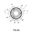
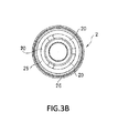
- the retainer 2 is provided with a small outer diameter portion 2a and a large outer diameter portion 2b having a larger outer diameter than the small outer diameter portion 2a and formed on a side of the retainer 2 opposite to the piston 1 coaxially with the small outer diameter portion 2a, and is inserted into the inside of the skirt portion 1d of the piston 1.
- the small outer diameter portion 2a is formed to have the outer diameter smaller than an inner diameter of the skirt portion 1d and a side thereof opposite to the piston 1 projects from the skirt portion 1d. Further, there is a clearance between the outer periphery of the large outer diameter portion 2b and the cylinder 5 so as not to prevent the working fluid in the other chamber B from flowing into the outer peripheral side flow passages 3b.
- the plurality of retainer through holes 20 formed in the retainer 2 are respectively formed into arcuate shapes and arranged at equal intervals along the circumferential direction of the retainer 2.
- Deformable elastic deforming portions 21 are formed between the plurality of retainer through holes 20. It should be noted that a cross-section of the retainer shown in FIG. 1 is a Y-Y cross-section of FIG. 3A .
- a flow passage area of the retainer through holes 20 is set to be not smaller than that of the valve disk through holes 10.
- the flow passage area of the retainer through holes 20 is the sum of opening areas of the retainer through holes 20. Since each retainer through hole 20 is identically shaped in the present embodiment, the flow passage area of the retainer through holes 20 can be obtained by a product of the opening area per retainer through hole 20 and the number of the retainer through holes 20. Further, the flow passage area of the valve disk through holes 10 is the sum of opening areas of the valve disk through holes 10. Since each valve disk through hole 10 is also identically shaped in the present embodiment, a total opening area of the valve disk through holes 10 can be obtained by a product of the opening area per valve disk through hole 10 and the number of the valve disk through holes 10.
- each of the retainer through holes 20 and the valve disk through holes 10 cut along a plane perpendicular to the central axis of the shock absorber D is set to be equal from the entrance to the exit in the present embodiment, the cross-sectional area of each of the retainer through holes 20 and the valve disk through holes 10 is equal to the opening area thereof.
- the retainer through holes 20 or the valve disk through holes 10 or both the retainer through holes 20 and the valve disk through holes 10 are partly reduced in diameter, cross-section areas of narrowest parts are equivalent to opening areas.
- annular window 22 continuous with the retainer through holes 20 an annular outer peripheral seat surface 23 surrounding the outer periphery of the window 22 and an annular inner peripheral seat surface 24 raised at an inner peripheral side of the window 22 are formed on a surface of the retainer 2 near the piston 1. Further, the outer and inner peripheral seat surfaces 23, 24 are formed to meet the valve seat 16 and the seat portion 17 of the piston 1 when the retainer 2 is placed on the piston 1 ( FIG. 1 ).
- annular window 25 continuous with the retainer through holes 20 and a valve seat 26 in the form of a ring having a large diameter and surrounding the outer periphery of the window 25 are formed on a surface of the retainer 2 opposite to the piston 1.
- a side of the inner peripheral side flow passage 3a in the other chamber B is closed by the leaf valves 4a.
- the shock absorber D When a piston speed is in a low speed region during extension of the shock absorber D in which the piston rod 6 comes out of the cylinder 5, the pressurized working fluid in the one chamber A moves to the other chamber B through the cuts 40 of the leaf valves 4a, 4b.
- the shock absorber D generates a damping force with a square-law characteristic by the orifices.
- the shock absorber D When the piston speed increases beyond the low speed region and reaches a middle speed region during extension of the shock absorber D, the pressurized working fluid in the one chamber A deflects outer peripheral parts of the leaf valves 4a and moves to the other chamber B through a clearance formed between the valve seat 26 of the retainer 2 and the outer peripheral parts of the leaf valves 4a.
- the shock absorber D generates a damping force with a proportional characteristic by the leaf valves 4a.
- the shock absorber D When the piston speed further increases and reaches a high speed region and the leaf valves 4a are opened to a certain extent during extension of the shock absorber D, the shock absorber D generates a damping force with a port characteristic by resistance produced when the working fluid passes in the inner peripheral side flow passage 3a.
- the shock absorber D When the piston speed is in the low speed region during contraction of the shock absorber D in which the piston rod 6 enters the cylinder 5, the pressurized working fluid in the other chamber B moves to the one chamber A through the cuts 40 of the leaf valves 4a, 4b.
- the shock absorber D generates a damping force with a square-law characteristic by the orifices.
- the pressurized working fluid in the other chamber B deflects outer peripheral parts of the leaf valves 4b and moves to the one chamber A through a clearance formed between the valve seat 13 of the piston 1 and the outer peripheral parts of the leaf valves 4b.
- the shock absorber D generates a damping force with a proportional characteristic by the leaf valves 4b.
- the shock absorber D When the piston speed further increases and reaches the high speed region and the leaf valves 4b are opened to a certain extent during contraction of the shock absorber D, the shock absorber D generates a damping force with a port characteristic by resistance produced when the working fluid passes in the outer peripheral side flow passages 3b.
- FIG. 5 is a sectional view showing a piston unit of a shock absorber to which a damping valve of a comparative example is applied.
- a shock absorber D1 to which the damping valve of the comparative example is applied is provided with a piston 100 partitioning one chamber A and another chamber B, and a retainer 200 provided to be placed on the piston 100 as shown in FIG. 5 .
- shock absorber D1 is provided with an inner peripheral side flow passage 300a configured to include a valve disk through hole 110 formed in an inner peripheral side of the piston 100 and a retainer through hole 210 formed in the retainer 200 and allowing communication between the one and the other chambers A, B, and an outer peripheral side flow passage 300b formed in an outer peripheral side of the piston 100 and allowing communication between the one and the other chambers A, B.
- a window 101 continuous with the outer peripheral side flow passage 300b and a valve seat 102 surrounding the outer periphery of the window 101 are formed on a surface of the piston 100 opposite to the retainer 200. Further, a window 201 continuous with the inner peripheral side flow passage 300a and a valve seat 202 surrounding the outer periphery of the window 201 are formed on a surface of the retainer 200 opposite to the piston 100.
- the outer peripheral parts of leaf valves 4a, 4b in the form of annular plates are respectively seated on the valve seats 202, 102 and openably close the exits of the inner and outer peripheral side flow passages 300a, 300b.
- the leaf valves 4a having a large diameter and easily deflectable can be used since a diameter of the valve seat 202 on which the leaf valves 4a corresponding to the inner peripheral side flow passage 300a are seated can be made larger by laminating the leaf valves 4a via the retainer 200 even if the flow passages are formed in the outer and inner peripheral sides of the piston 100.
- a damping force characteristic can be variously changed by replaceably mounting retainers 200 having various dimensions and shapes.
- the shock absorber D1 generates a damping force with a port characteristic due to resistance during the passage of the working fluid in the inner peripheral side flow passage 300a when the leaf valves 4a are opened to a certain extent.
- the damping force with the port characteristic can be changed by a replacement with a retainer 200 having a different flow passage area of the retainer through hole 210.
- the damping force with the port characteristic can be set by the flow passage area of the valve disk through holes 10 and the damping force characteristic can be changed by a replacement with a piston 1 having a different flow passage area.
- the damping coefficient of the port characteristic can be increased and an existing piston can be utilized even in the case of singly using the piston 1.
- the piston 1 may be singly used without providing the retainer 2.
- the piston 1 including the valve disk through holes 10 having a largest flow passage area is the piston 1A
- the piston 1 including the valve disk through holes 10 having a second largest flow passage area is the piston 1B
- the piston 1 including the valve disk through holes 10 having a smallest flow passage area is the piston 1C
- the flow passage area of the retainer through holes 20 formed in the retainer 2 to be combined with the pistons 1A, 1B and 1C is set to be not smaller than the flow passage area of the valve disk through holes 10 of the piston 1A.
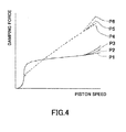
- P1, P2 and P3 shown in solid line in FIG. 4 represent damping characteristics when the three types of pistons 1A, 1B and 1C are respectively used in combination with the retainer 2 including the retainer through holes 20 having a flow passage area set to be not smaller than that of the valve disk through holes 10 of the piston 1A.
- P1 indicates a case where the piston 1A is used
- P2 indicates a case where the piston 1B is used
- P3 indicates a case where the piston 1C is used.
- P4, P5 and P6 shown in broken line in FIG. 4 represent damping characteristics when the three types of pistons 1A, 1B and 1C are singly used. In this case, P1 changes to P4, P2 changes to P5 and P3 changes to P6.
- n damping force characteristics in the case of singly using the piston and n damping force characteristics in the case of using the retainer 2 and the piston 1 in combination i.e. 2n damping force characteristics can be realized. That is, according to the present embodiment, various damping force characteristics can be realized by a small number of components.
- the piston 1 is formed with the inner peripheral side flow passage 3a in the inner peripheral side and the outer peripheral side flow passages 3b in the outer peripheral side, the diameter of the leaf valves 4a becomes smaller and the damping coefficient when the piston speed is in the middle speed region becomes larger when the leaf valves 4a for closing the exit of the inner peripheral side flow passage 3a are directly seated on the valve seat 16 formed on the piston 1.
- the leaf valves 4a having a large diameter and easily deflectable and enable the damping coefficient when the piston speed is in the middle speed region to be decreased by increasing the diameter of the valve seat 26 on which the leaf valves 4a for closing the inner peripheral side flow passage 3a are seated in the configuration provided with the retainer 2.
- valve disk through holes 10 and the retainer through holes 20 communicate via the windows 15, 22 in the present embodiment, it is not necessary to position the valve disk through holes 10 and the retainer through holes 20 in the circumferential direction.
- valve disk through holes 10 and the outer peripheral side flow passages 3b penetrate through the piston 1 in the direction of the central axis of the shock absorber D and the retainer through holes 20 penetrate through the retainer 2 in the direction of the central axis of the shock absorber D, the valve disk through holes 10, the outer peripheral side flow passages 3b and the retainer through holes 20 can be easily formed.
- the piston main body 1b is provided with the skirt portion 1d and the small outer diameter portion 2a of the retainer 2 is inserted into the skirt portion 1d, it is possible to ensure the width of the slide contact portion 1c in the direction of the central axis of the shock absorber D, shorten the width when the piston 1 and the retainer 2 are assembled and miniaturize the shock absorber D.
- damping valve in the above embodiment is applied to the piston unit of the shock absorber D, it may be applied to a base valve unit of the shock absorber D.
- shock absorber D is a hydraulic shock absorber using liquid as the working fluid, it may be a pneumatic shock absorber using gas as the working fluid.
- valve disk through holes 10 and the retainer through holes 20 communicate via the windows 15, 22 formed on each mating surface of the piston 1 and the retainer 2, positioning in the circumferential direction is not necessary if a window is formed on either one of the piston 1 and the retainer 2. Further, if positioning is possible, the valve disk through holes 10 and the retainer through holes 20 may communicate without via the windows 15, 22.
- the shapes of the piston 1 and the retainer 2, the shapes and the numbers of the valve disk through holes 10, the outer peripheral side flow passages 3b and the retainer through holes 20 are not limited to the above ones and can be changed as appropriate.
- the retainer 2 in the above embodiment includes the elastic deforming portions 21 between adjacent ones of the retainer through holes 20, whereby the leakage of the working fluid in the middle of the inner peripheral side flow passage 3a can be prevented.
- the elastic deforming portions 21 may not be included if this effect can be achieved.
Landscapes
- Engineering & Computer Science (AREA)
- General Engineering & Computer Science (AREA)
- Mechanical Engineering (AREA)
- Fluid-Damping Devices (AREA)
Applications Claiming Priority (2)
| Application Number | Priority Date | Filing Date | Title |
|---|---|---|---|
| JP2012056846A JP5785510B2 (ja) | 2012-03-14 | 2012-03-14 | 緩衝器のバルブ構造 |
| PCT/JP2013/053802 WO2013136911A1 (ja) | 2012-03-14 | 2013-02-18 | 緩衝器の減衰バルブ |
Publications (3)
| Publication Number | Publication Date |
|---|---|
| EP2801733A1 true EP2801733A1 (de) | 2014-11-12 |
| EP2801733A4 EP2801733A4 (de) | 2015-12-09 |
| EP2801733B1 EP2801733B1 (de) | 2017-05-17 |
Family
ID=49160830
Family Applications (1)
| Application Number | Title | Priority Date | Filing Date |
|---|---|---|---|
| EP13762028.2A Active EP2801733B1 (de) | 2012-03-14 | 2013-02-18 | Dämpfungsventil für stossdämpfer |
Country Status (6)
| Country | Link |
|---|---|
| US (1) | US9347512B2 (de) |
| EP (1) | EP2801733B1 (de) |
| JP (1) | JP5785510B2 (de) |
| KR (1) | KR101773238B1 (de) |
| CN (1) | CN104094012B (de) |
| WO (1) | WO2013136911A1 (de) |
Cited By (1)
| Publication number | Priority date | Publication date | Assignee | Title |
|---|---|---|---|---|
| US11859891B2 (en) | 2019-07-17 | 2024-01-02 | Electrolux Home Products, Inc. | Appliance air freshener |
Families Citing this family (12)
| Publication number | Priority date | Publication date | Assignee | Title |
|---|---|---|---|---|
| JP5941359B2 (ja) * | 2012-07-10 | 2016-06-29 | Kyb株式会社 | 緩衝器のバルブ構造 |
| KR101760908B1 (ko) * | 2013-12-09 | 2017-07-24 | 주식회사 만도 | 쇽업소버 |
| JP6567267B2 (ja) * | 2014-10-31 | 2019-08-28 | 千博産業株式会社 | 構造物の制振装置 |
| CN107208728B (zh) * | 2015-01-30 | 2019-12-13 | 日立汽车系统株式会社 | 流体压缓冲器 |
| JP6401862B2 (ja) * | 2015-07-22 | 2018-10-10 | Kyb株式会社 | ピストン |
| US11035491B2 (en) | 2017-07-03 | 2021-06-15 | Continental Automotive Systems, Inc. | Fuel pump solenoid having hydraulic damping |
| CN110173535B (zh) * | 2019-06-10 | 2024-04-05 | 伯科姆汽车零部件系统(苏州)有限公司 | 一种频率自感应阻尼调节减振器复原阀总成 |
| US11719304B2 (en) | 2020-03-27 | 2023-08-08 | DRiV Automotive Inc. | Damper assembly |
| AU2021264761B2 (en) * | 2020-04-26 | 2023-09-07 | Ningbo Kasico Shock Absorber Manufacture Co., Ltd. | Self-variable force hydraulic damper |
| US11808323B2 (en) * | 2021-02-15 | 2023-11-07 | DRiV Automotive Inc. | Open bleed-base valve |
| US20240376953A1 (en) * | 2023-05-08 | 2024-11-14 | DRiV Automotive Inc. | Fulcrum and check discs for shock absorber with optimized bleed range and tuneability |
| WO2025177648A1 (ja) * | 2024-02-22 | 2025-08-28 | Astemo株式会社 | 焼結体および焼結体の製造方法 |
Family Cites Families (36)
| Publication number | Priority date | Publication date | Assignee | Title |
|---|---|---|---|---|
| GB2226620B (en) * | 1988-10-25 | 1992-11-04 | Tokico Ltd | Hydraulic damper |
| US5148897A (en) * | 1991-07-18 | 1992-09-22 | Monroe Auto Equipment Company | Piston valving for shock absorbers |
| JPH07167191A (ja) | 1993-12-15 | 1995-07-04 | Tokico Ltd | 油圧緩衝器 |
| JP3646228B2 (ja) * | 1995-03-31 | 2005-05-11 | 株式会社日立製作所 | 減衰力調整式油圧緩衝器 |
| US6499572B2 (en) * | 1996-04-10 | 2002-12-31 | Kayaba Kogyo Kabushiki Kaisha | Damping force generator |
| JPH10103512A (ja) | 1996-09-30 | 1998-04-21 | Showa:Kk | 油圧緩衝器のピストン構造 |
| JPH11101293A (ja) * | 1997-09-26 | 1999-04-13 | Tokico Ltd | 電気粘性流体を用いたダンパ |
| JPH11101292A (ja) * | 1997-09-30 | 1999-04-13 | Tokico Ltd | 減衰力調整式油圧緩衝器 |
| DE10013638C1 (de) * | 2000-03-18 | 2001-09-20 | Krupp Bilstein Gmbh | Stoßdämpferkolben, bestehend aus zwei Kolbenhälften |
| JP2002048180A (ja) | 2000-07-31 | 2002-02-15 | Tokico Ltd | 油圧緩衝器 |
| DE10051971C1 (de) * | 2000-10-20 | 2002-03-28 | Krupp Bilstein Gmbh | Arbeitskolben für einen hydraulischen Stoßdämpfer und Verfahren zu seiner Hers tellung |
| ATE421050T1 (de) * | 2004-02-23 | 2009-01-15 | Delphi Tech Inc | Hydraulischer aufhängungsdämpfer |
| DE102005008162B3 (de) * | 2005-02-23 | 2006-08-03 | Zf Friedrichshafen Ag | Dämpfventil |
| JP2006275216A (ja) | 2005-03-30 | 2006-10-12 | Hitachi Ltd | 油圧緩衝器のピストン構造 |
| DE102006028745A1 (de) * | 2005-06-21 | 2007-05-03 | Tenneco Automotive Operating Company Inc., Lake Forest | Vierteiliger Kolben |
| JP4987283B2 (ja) * | 2005-11-09 | 2012-07-25 | カヤバ工業株式会社 | 緩衝器のバルブ構造および緩衝器 |
| KR100773363B1 (ko) * | 2006-01-23 | 2007-11-05 | 주식회사 만도 | 선형의 감쇠력 특성 구현을 위한 쇽업소버 |
| JP2008138696A (ja) * | 2006-11-30 | 2008-06-19 | Showa Corp | 油圧緩衝器の分割ピストン構造 |
| JP4898563B2 (ja) | 2007-06-06 | 2012-03-14 | カヤバ工業株式会社 | ピストン |
| KR101227384B1 (ko) * | 2008-03-20 | 2013-01-30 | 주식회사 만도 | 쇽업소버의 밸브장치 |
| JP5115814B2 (ja) * | 2008-05-30 | 2013-01-09 | 日立オートモティブシステムズ株式会社 | 緩衝器 |
| DK2141382T3 (da) * | 2008-07-02 | 2012-09-17 | Koni Bv | Hydraulikventil |
| JP5192441B2 (ja) * | 2009-05-20 | 2013-05-08 | カヤバ工業株式会社 | 減衰バルブ |
| JP5418778B2 (ja) * | 2010-02-26 | 2014-02-19 | 日立オートモティブシステムズ株式会社 | 緩衝器 |
| JP2011179550A (ja) | 2010-02-26 | 2011-09-15 | Hitachi Automotive Systems Ltd | 緩衝器 |
| JP5648790B2 (ja) | 2010-08-31 | 2015-01-07 | 日立オートモティブシステムズ株式会社 | 緩衝器 |
| KR101218839B1 (ko) * | 2010-09-07 | 2013-01-07 | 주식회사 만도 | 쇽업소버 |
| KR101254287B1 (ko) * | 2011-06-09 | 2013-04-12 | 주식회사 만도 | 가변유로를 갖는 쇽업소버의 밸브 구조 |
| KR101288613B1 (ko) * | 2011-08-11 | 2013-07-22 | 주식회사 만도 | 쇽업소버의 피스톤 어셈블리 |
| KR101374875B1 (ko) * | 2011-12-30 | 2014-03-18 | 주식회사 만도 | 쇽업소버의 피스톤 어셈블리 |
| JP5833957B2 (ja) * | 2012-03-14 | 2015-12-16 | Kyb株式会社 | 緩衝器のバルブ構造 |
| KR101374877B1 (ko) * | 2012-06-13 | 2014-03-18 | 주식회사 만도 | 쇽업소버의 피스톤 어셈블리 |
| JP5941359B2 (ja) * | 2012-07-10 | 2016-06-29 | Kyb株式会社 | 緩衝器のバルブ構造 |
| US9103402B2 (en) * | 2013-02-21 | 2015-08-11 | Mando Corporation | Shock absorber |
| KR101876915B1 (ko) * | 2013-10-28 | 2018-08-09 | 주식회사 만도 | 쇽업소버의 피스톤 밸브 어셈블리 |
| KR101760908B1 (ko) * | 2013-12-09 | 2017-07-24 | 주식회사 만도 | 쇽업소버 |
-
2012
- 2012-03-14 JP JP2012056846A patent/JP5785510B2/ja active Active
-
2013
- 2013-02-18 US US14/379,859 patent/US9347512B2/en active Active
- 2013-02-18 EP EP13762028.2A patent/EP2801733B1/de active Active
- 2013-02-18 CN CN201380007489.9A patent/CN104094012B/zh active Active
- 2013-02-18 WO PCT/JP2013/053802 patent/WO2013136911A1/ja not_active Ceased
- 2013-02-18 KR KR1020147023076A patent/KR101773238B1/ko not_active Expired - Fee Related
Cited By (1)
| Publication number | Priority date | Publication date | Assignee | Title |
|---|---|---|---|---|
| US11859891B2 (en) | 2019-07-17 | 2024-01-02 | Electrolux Home Products, Inc. | Appliance air freshener |
Also Published As
| Publication number | Publication date |
|---|---|
| JP2013190045A (ja) | 2013-09-26 |
| CN104094012B (zh) | 2016-02-24 |
| KR101773238B1 (ko) | 2017-08-31 |
| EP2801733B1 (de) | 2017-05-17 |
| CN104094012A (zh) | 2014-10-08 |
| JP5785510B2 (ja) | 2015-09-30 |
| WO2013136911A1 (ja) | 2013-09-19 |
| EP2801733A4 (de) | 2015-12-09 |
| US20150034437A1 (en) | 2015-02-05 |
| US9347512B2 (en) | 2016-05-24 |
| KR20140114050A (ko) | 2014-09-25 |
Similar Documents
| Publication | Publication Date | Title |
|---|---|---|
| US9347512B2 (en) | Damping valve for shock absorber | |
| US9410595B2 (en) | Damping valve for shock absorber | |
| US10995813B2 (en) | Shock absorber | |
| KR102588959B1 (ko) | 완충기 | |
| EP2787242A1 (de) | Dämpfungsventil für stossdämpfer | |
| US11199241B2 (en) | Damper | |
| US11655875B2 (en) | Damping valve and shock absorber | |
| US12038063B2 (en) | Shock absorber | |
| US20160356335A1 (en) | Pressure damping device and elastic member | |
| US10316922B2 (en) | Shock absorber | |
| US20230079968A1 (en) | Damping-force generation mechanism and pressure shock absorber | |
| JP2023516046A (ja) | 改良型油圧ダンパースプール弁 | |
| US12571451B2 (en) | Shock absorber | |
| DE112011102695T5 (de) | Verbesserungen an Stoßdämpfern | |
| US12163572B2 (en) | Shock absorber | |
| JP6198926B1 (ja) | 油圧緩衝器 | |
| US20250383004A1 (en) | Damping force generation mechanism | |
| WO2023095571A1 (ja) | バルブおよび緩衝器 | |
| JP5281326B2 (ja) | バルブ | |
| JP2005195046A (ja) | シリンダ装置 | |
| KR20240022632A (ko) | 실린더 장치 및 제어 밸브 장치 | |
| JP2008309213A (ja) | 油圧緩衝器の減衰力発生構造 |
Legal Events
| Date | Code | Title | Description |
|---|---|---|---|
| PUAI | Public reference made under article 153(3) epc to a published international application that has entered the european phase |
Free format text: ORIGINAL CODE: 0009012 |
|
| 17P | Request for examination filed |
Effective date: 20140808 |
|
| AK | Designated contracting states |
Kind code of ref document: A1 Designated state(s): AL AT BE BG CH CY CZ DE DK EE ES FI FR GB GR HR HU IE IS IT LI LT LU LV MC MK MT NL NO PL PT RO RS SE SI SK SM TR |
|
| DAX | Request for extension of the european patent (deleted) | ||
| RA4 | Supplementary search report drawn up and despatched (corrected) |
Effective date: 20151109 |
|
| RIC1 | Information provided on ipc code assigned before grant |
Ipc: F16F 9/32 20060101ALI20151103BHEP Ipc: F16K 15/14 20060101ALI20151103BHEP Ipc: F16F 9/34 20060101AFI20151103BHEP Ipc: F16F 9/348 20060101ALI20151103BHEP |
|
| RAP1 | Party data changed (applicant data changed or rights of an application transferred) |
Owner name: KYB CORPORATION |
|
| RIC1 | Information provided on ipc code assigned before grant |
Ipc: F16F 9/32 20060101ALI20161104BHEP Ipc: F16F 9/348 20060101ALI20161104BHEP Ipc: F16F 9/34 20060101AFI20161104BHEP Ipc: F16K 15/14 20060101ALI20161104BHEP |
|
| GRAP | Despatch of communication of intention to grant a patent |
Free format text: ORIGINAL CODE: EPIDOSNIGR1 |
|
| INTG | Intention to grant announced |
Effective date: 20161221 |
|
| GRAS | Grant fee paid |
Free format text: ORIGINAL CODE: EPIDOSNIGR3 |
|
| GRAA | (expected) grant |
Free format text: ORIGINAL CODE: 0009210 |
|
| AK | Designated contracting states |
Kind code of ref document: B1 Designated state(s): AL AT BE BG CH CY CZ DE DK EE ES FI FR GB GR HR HU IE IS IT LI LT LU LV MC MK MT NL NO PL PT RO RS SE SI SK SM TR |
|
| REG | Reference to a national code |
Ref country code: GB Ref legal event code: FG4D |
|
| RIN1 | Information on inventor provided before grant (corrected) |
Inventor name: YAMADA, HIDEKI |
|
| REG | Reference to a national code |
Ref country code: CH Ref legal event code: EP |
|
| REG | Reference to a national code |
Ref country code: IE Ref legal event code: FG4D |
|
| REG | Reference to a national code |
Ref country code: AT Ref legal event code: REF Ref document number: 894763 Country of ref document: AT Kind code of ref document: T Effective date: 20170615 |
|
| REG | Reference to a national code |
Ref country code: DE Ref legal event code: R096 Ref document number: 602013021299 Country of ref document: DE |
|
| REG | Reference to a national code |
Ref country code: NL Ref legal event code: MP Effective date: 20170517 |
|
| REG | Reference to a national code |
Ref country code: LT Ref legal event code: MG4D |
|
| REG | Reference to a national code |
Ref country code: AT Ref legal event code: MK05 Ref document number: 894763 Country of ref document: AT Kind code of ref document: T Effective date: 20170517 |
|
| PG25 | Lapsed in a contracting state [announced via postgrant information from national office to epo] |
Ref country code: FI Free format text: LAPSE BECAUSE OF FAILURE TO SUBMIT A TRANSLATION OF THE DESCRIPTION OR TO PAY THE FEE WITHIN THE PRESCRIBED TIME-LIMIT Effective date: 20170517 Ref country code: AT Free format text: LAPSE BECAUSE OF FAILURE TO SUBMIT A TRANSLATION OF THE DESCRIPTION OR TO PAY THE FEE WITHIN THE PRESCRIBED TIME-LIMIT Effective date: 20170517 Ref country code: GR Free format text: LAPSE BECAUSE OF FAILURE TO SUBMIT A TRANSLATION OF THE DESCRIPTION OR TO PAY THE FEE WITHIN THE PRESCRIBED TIME-LIMIT Effective date: 20170818 Ref country code: ES Free format text: LAPSE BECAUSE OF FAILURE TO SUBMIT A TRANSLATION OF THE DESCRIPTION OR TO PAY THE FEE WITHIN THE PRESCRIBED TIME-LIMIT Effective date: 20170517 Ref country code: NO Free format text: LAPSE BECAUSE OF FAILURE TO SUBMIT A TRANSLATION OF THE DESCRIPTION OR TO PAY THE FEE WITHIN THE PRESCRIBED TIME-LIMIT Effective date: 20170817 Ref country code: HR Free format text: LAPSE BECAUSE OF FAILURE TO SUBMIT A TRANSLATION OF THE DESCRIPTION OR TO PAY THE FEE WITHIN THE PRESCRIBED TIME-LIMIT Effective date: 20170517 Ref country code: LT Free format text: LAPSE BECAUSE OF FAILURE TO SUBMIT A TRANSLATION OF THE DESCRIPTION OR TO PAY THE FEE WITHIN THE PRESCRIBED TIME-LIMIT Effective date: 20170517 |
|
| PG25 | Lapsed in a contracting state [announced via postgrant information from national office to epo] |
Ref country code: BG Free format text: LAPSE BECAUSE OF FAILURE TO SUBMIT A TRANSLATION OF THE DESCRIPTION OR TO PAY THE FEE WITHIN THE PRESCRIBED TIME-LIMIT Effective date: 20170817 Ref country code: PL Free format text: LAPSE BECAUSE OF FAILURE TO SUBMIT A TRANSLATION OF THE DESCRIPTION OR TO PAY THE FEE WITHIN THE PRESCRIBED TIME-LIMIT Effective date: 20170517 Ref country code: RS Free format text: LAPSE BECAUSE OF FAILURE TO SUBMIT A TRANSLATION OF THE DESCRIPTION OR TO PAY THE FEE WITHIN THE PRESCRIBED TIME-LIMIT Effective date: 20170517 Ref country code: NL Free format text: LAPSE BECAUSE OF FAILURE TO SUBMIT A TRANSLATION OF THE DESCRIPTION OR TO PAY THE FEE WITHIN THE PRESCRIBED TIME-LIMIT Effective date: 20170517 Ref country code: SE Free format text: LAPSE BECAUSE OF FAILURE TO SUBMIT A TRANSLATION OF THE DESCRIPTION OR TO PAY THE FEE WITHIN THE PRESCRIBED TIME-LIMIT Effective date: 20170517 Ref country code: LV Free format text: LAPSE BECAUSE OF FAILURE TO SUBMIT A TRANSLATION OF THE DESCRIPTION OR TO PAY THE FEE WITHIN THE PRESCRIBED TIME-LIMIT Effective date: 20170517 Ref country code: IS Free format text: LAPSE BECAUSE OF FAILURE TO SUBMIT A TRANSLATION OF THE DESCRIPTION OR TO PAY THE FEE WITHIN THE PRESCRIBED TIME-LIMIT Effective date: 20170917 |
|
| PG25 | Lapsed in a contracting state [announced via postgrant information from national office to epo] |
Ref country code: RO Free format text: LAPSE BECAUSE OF FAILURE TO SUBMIT A TRANSLATION OF THE DESCRIPTION OR TO PAY THE FEE WITHIN THE PRESCRIBED TIME-LIMIT Effective date: 20170517 Ref country code: DK Free format text: LAPSE BECAUSE OF FAILURE TO SUBMIT A TRANSLATION OF THE DESCRIPTION OR TO PAY THE FEE WITHIN THE PRESCRIBED TIME-LIMIT Effective date: 20170517 Ref country code: EE Free format text: LAPSE BECAUSE OF FAILURE TO SUBMIT A TRANSLATION OF THE DESCRIPTION OR TO PAY THE FEE WITHIN THE PRESCRIBED TIME-LIMIT Effective date: 20170517 Ref country code: CZ Free format text: LAPSE BECAUSE OF FAILURE TO SUBMIT A TRANSLATION OF THE DESCRIPTION OR TO PAY THE FEE WITHIN THE PRESCRIBED TIME-LIMIT Effective date: 20170517 Ref country code: SK Free format text: LAPSE BECAUSE OF FAILURE TO SUBMIT A TRANSLATION OF THE DESCRIPTION OR TO PAY THE FEE WITHIN THE PRESCRIBED TIME-LIMIT Effective date: 20170517 |
|
| REG | Reference to a national code |
Ref country code: DE Ref legal event code: R097 Ref document number: 602013021299 Country of ref document: DE |
|
| PG25 | Lapsed in a contracting state [announced via postgrant information from national office to epo] |
Ref country code: IT Free format text: LAPSE BECAUSE OF FAILURE TO SUBMIT A TRANSLATION OF THE DESCRIPTION OR TO PAY THE FEE WITHIN THE PRESCRIBED TIME-LIMIT Effective date: 20170517 Ref country code: SM Free format text: LAPSE BECAUSE OF FAILURE TO SUBMIT A TRANSLATION OF THE DESCRIPTION OR TO PAY THE FEE WITHIN THE PRESCRIBED TIME-LIMIT Effective date: 20170517 |
|
| PLBE | No opposition filed within time limit |
Free format text: ORIGINAL CODE: 0009261 |
|
| STAA | Information on the status of an ep patent application or granted ep patent |
Free format text: STATUS: NO OPPOSITION FILED WITHIN TIME LIMIT |
|
| 26N | No opposition filed |
Effective date: 20180220 |
|
| PG25 | Lapsed in a contracting state [announced via postgrant information from national office to epo] |
Ref country code: SI Free format text: LAPSE BECAUSE OF FAILURE TO SUBMIT A TRANSLATION OF THE DESCRIPTION OR TO PAY THE FEE WITHIN THE PRESCRIBED TIME-LIMIT Effective date: 20170517 |
|
| REG | Reference to a national code |
Ref country code: CH Ref legal event code: PL |
|
| PG25 | Lapsed in a contracting state [announced via postgrant information from national office to epo] |
Ref country code: MC Free format text: LAPSE BECAUSE OF FAILURE TO SUBMIT A TRANSLATION OF THE DESCRIPTION OR TO PAY THE FEE WITHIN THE PRESCRIBED TIME-LIMIT Effective date: 20170517 |
|
| GBPC | Gb: european patent ceased through non-payment of renewal fee |
Effective date: 20180218 |
|
| REG | Reference to a national code |
Ref country code: IE Ref legal event code: MM4A |
|
| REG | Reference to a national code |
Ref country code: BE Ref legal event code: MM Effective date: 20180228 |
|
| PG25 | Lapsed in a contracting state [announced via postgrant information from national office to epo] |
Ref country code: LI Free format text: LAPSE BECAUSE OF NON-PAYMENT OF DUE FEES Effective date: 20180228 Ref country code: LU Free format text: LAPSE BECAUSE OF NON-PAYMENT OF DUE FEES Effective date: 20180218 Ref country code: CH Free format text: LAPSE BECAUSE OF NON-PAYMENT OF DUE FEES Effective date: 20180228 |
|
| REG | Reference to a national code |
Ref country code: FR Ref legal event code: ST Effective date: 20181031 |
|
| PG25 | Lapsed in a contracting state [announced via postgrant information from national office to epo] |
Ref country code: IE Free format text: LAPSE BECAUSE OF NON-PAYMENT OF DUE FEES Effective date: 20180218 |
|
| PG25 | Lapsed in a contracting state [announced via postgrant information from national office to epo] |
Ref country code: BE Free format text: LAPSE BECAUSE OF NON-PAYMENT OF DUE FEES Effective date: 20180228 Ref country code: GB Free format text: LAPSE BECAUSE OF NON-PAYMENT OF DUE FEES Effective date: 20180218 Ref country code: FR Free format text: LAPSE BECAUSE OF NON-PAYMENT OF DUE FEES Effective date: 20180228 |
|
| PG25 | Lapsed in a contracting state [announced via postgrant information from national office to epo] |
Ref country code: MT Free format text: LAPSE BECAUSE OF NON-PAYMENT OF DUE FEES Effective date: 20180218 |
|
| PG25 | Lapsed in a contracting state [announced via postgrant information from national office to epo] |
Ref country code: TR Free format text: LAPSE BECAUSE OF FAILURE TO SUBMIT A TRANSLATION OF THE DESCRIPTION OR TO PAY THE FEE WITHIN THE PRESCRIBED TIME-LIMIT Effective date: 20170517 |
|
| PG25 | Lapsed in a contracting state [announced via postgrant information from national office to epo] |
Ref country code: PT Free format text: LAPSE BECAUSE OF FAILURE TO SUBMIT A TRANSLATION OF THE DESCRIPTION OR TO PAY THE FEE WITHIN THE PRESCRIBED TIME-LIMIT Effective date: 20170517 Ref country code: HU Free format text: LAPSE BECAUSE OF FAILURE TO SUBMIT A TRANSLATION OF THE DESCRIPTION OR TO PAY THE FEE WITHIN THE PRESCRIBED TIME-LIMIT; INVALID AB INITIO Effective date: 20130218 |
|
| PG25 | Lapsed in a contracting state [announced via postgrant information from national office to epo] |
Ref country code: MK Free format text: LAPSE BECAUSE OF NON-PAYMENT OF DUE FEES Effective date: 20170517 Ref country code: CY Free format text: LAPSE BECAUSE OF FAILURE TO SUBMIT A TRANSLATION OF THE DESCRIPTION OR TO PAY THE FEE WITHIN THE PRESCRIBED TIME-LIMIT Effective date: 20170517 |
|
| PG25 | Lapsed in a contracting state [announced via postgrant information from national office to epo] |
Ref country code: AL Free format text: LAPSE BECAUSE OF FAILURE TO SUBMIT A TRANSLATION OF THE DESCRIPTION OR TO PAY THE FEE WITHIN THE PRESCRIBED TIME-LIMIT Effective date: 20170517 |
|
| PGFP | Annual fee paid to national office [announced via postgrant information from national office to epo] |
Ref country code: DE Payment date: 20260218 Year of fee payment: 14 |