EP2799355B1 - Kunststoffbehälter - Google Patents
Kunststoffbehälter Download PDFInfo
- Publication number
- EP2799355B1 EP2799355B1 EP14166627.1A EP14166627A EP2799355B1 EP 2799355 B1 EP2799355 B1 EP 2799355B1 EP 14166627 A EP14166627 A EP 14166627A EP 2799355 B1 EP2799355 B1 EP 2799355B1
- Authority
- EP
- European Patent Office
- Prior art keywords
- container
- rim
- contact face
- base
- plastic container
- Prior art date
- Legal status (The legal status is an assumption and is not a legal conclusion. Google has not performed a legal analysis and makes no representation as to the accuracy of the status listed.)
- Active
Links
Images


Classifications
-
- B—PERFORMING OPERATIONS; TRANSPORTING
- B65—CONVEYING; PACKING; STORING; HANDLING THIN OR FILAMENTARY MATERIAL
- B65D—CONTAINERS FOR STORAGE OR TRANSPORT OF ARTICLES OR MATERIALS, e.g. BAGS, BARRELS, BOTTLES, BOXES, CANS, CARTONS, CRATES, DRUMS, JARS, TANKS, HOPPERS, FORWARDING CONTAINERS; ACCESSORIES, CLOSURES, OR FITTINGS THEREFOR; PACKAGING ELEMENTS; PACKAGES
- B65D1/00—Rigid or semi-rigid containers having bodies formed in one piece, e.g. by casting metallic material, by moulding plastics, by blowing vitreous material, by throwing ceramic material, by moulding pulped fibrous material or by deep-drawing operations performed on sheet material
- B65D1/22—Boxes or like containers with side walls of substantial depth for enclosing contents
Definitions
- the invention relates to a plastic container with tread.
- the DE 198 44 014 C1 describes a transport box made in one piece from plastic according to the preamble of claim 1, with a level in the middle region of the box bottom under which at least two parallel runners are in the edge region of the box, which are connected by transverse to the runners ribs with the bottom in that pockets which are open towards the outside and / or inside by the runners, the transverse ribs and the bottom bottom surface are formed, and in which the runners on the side facing the center of the box have a longitudinal section which is directed upwards.
- the WO 2011/120641 A1 describes a box-shaped plastic container for the transport and storage of goods with a grid-like webs reinforced bottom and ascending from this bottom side walls, wherein at least on the webs in the region of the bottom a reinforcing plate made of plastic is applied and fixed, which is characterized in that in the plastic of the reinforcing plate reinforcing fibers are pressed.
- the DE 203 15 302 U1 describes a plastic container manufactured in one piece by welding, in particular storage and transport box, which is provided on the lower surface of its bottom with ribs forming a Bodenffenfeld, and circumferentially along the bottom edge of an outer tread providing flat webs as a double bottom.
- the invention has for its object to provide an improved transport and storage container made of plastic.
- running rim is understood to mean that surface of the container with which the container at least partially rests on a floor surface.
- surface "Auffier Scheme” When rolling over a roller conveyor of the tread is the surface "Auffier Scheme", with which the plastic container runs onto the rollers of the roller conveyor and then gets into contact with the transport rollers of the roller conveyor.
- Embodiments of the invention could have the advantage of minimizing noise during sliding of the plastic container over the rollers of the roller conveyor. By increasing the middle ring, the contact surface becomes minimized, with the softer the container is in contact with the rollers of the roller conveyor.
- the first running surface is rounded at its sides facing the inner rim and / or the outer rim towards the receiving area of the container. This could have the advantage that the first tread of the middle ring does not run abruptly but steadily, evenly and gently onto a transport roller. This smoother rolling will minimize the noise associated with rolling up.
- Another advantage could be that vibrations of the plastic container are minimized by the softer curling. This makes it possible to transport such cargo in the plastic container, which is sensitive to shocks. These could be, for example, optical measuring instruments.
- the floor further comprises a second tread, wherein the second tread is guided from the outer corners of the outer rim to the first tread, wherein the second tread is increased relative to the inner rim and the outer rim.
- the outer ring is completely interrupted by the second tread several times.
- the increase of the second tread is identical to the increase of the first tread.
- the second tread may be rounded at its outer edge towards the receiving area of the container.
- the floor further comprises a third tread, wherein the third tread is guided perpendicular to the outside of the container from the outer edge of the outer rim to the first tread, wherein the third tread is increased relative to the inner rim and the outer rim.
- the increase of the third tread is e.g. identical to the increase in the first tread. Further, e.g. the third tread rounded at its outer edge towards the receiving area of the container. This could have the advantage that even when carrying high loads in the container interior, the emergence of the container bottom on transport rollers remains gentle.
- the container bottom could in particular asymmetrically bend down in the region of the container edge, nevertheless a gentle emergence is guaranteed even in the sagged area at the container edge by the additional "emergence aid" in the form of the third tread.
- the third running surface could thus ensure that a highly uniform loading edge of the container bottom is ensured under high load on the container bottom.
- the inner region towards the inner rim seen in the plane of the container bottom has a crowning, wherein the crown extends completely around the inner region.
- the crowning can simulate the hypothetical deformation of the bottom. In particular, in a rectangular shape of the container, this hypothetical deformation of the bottom will have a kind of oval shape when projected onto the plane of extension of the container bottom.
- the inner region is stretched more in the longitudinal direction of the container bottom than in the transverse direction of the container bottom, with the longitudinally extending crown differing from the transversely extending crown, it could be ensured that there is optimum space for deformation to take place Container bottom is created.
- the space available for the deformation is thus almost proportional to the expected spatial deformation of the soil.
- the interior of the floor is a ribbed floor.
- the ribs of the ribbed bottom could run perpendicular to the outer sides of the container, whereby in particular a power transmission from the container center to the container outer sides can be optimized.
- the ribbed bottom thus leads to an unintended bending of the soil in the region of the ribbed bottom is reduced.
- the ribbed bottom is additionally concave, that is curved in the direction of the container interior. This also helps to increase the carrying capacity of the container when loading at high loads. Forces acting on the bottom of the tank are transmitted evenly outwards towards the outer walls on the tread.
- the first tread and / or the second tread and / or the third tread are formed integrally with each other.
- the material of the first tread and the second tread is softer compared to the material of the inner rim and / or the outer rim. This makes it possible to optimize the noise characteristics when overflowing the tread over a roller conveyor in an efficient manner. With respect to the bottom and the rest of the container, however, a material could be selected, which is particularly impact resistant and stable.
- the outer rim has at its seen in the plane of the bottom outer region to the outside of the container open recess, the recess has a bottom side and a wall facing the receiving area top side, wherein the bottom side opposite the top resiliently formed is.
- Another advantage could be that vibrations of the plastic container are minimized by the softer curling. This makes it possible to transport such cargo in the plastic container, which is sensitive to shocks. These could be, for example, optical measuring instruments.
- the recess extends around the entire outside of the container. Thus, it does not matter in which direction the plastic container slides over the rollers of the roller conveyor. In every orientation there is a minimization of noise during sliding over.
- the recess is divided into a plurality of chambers by webs.
- the recess extends continuously around the entire outside of the container. While the latter has the advantage that the resilient properties of the recess can be better utilized, dividing the recess into a plurality of chambers by means of webs could have the advantage that the stability of the recess is increased. In particular, this could avoid that the region of the recess breaks off from the edge of the container.
- the plastic container further comprises a groove extending on the rear side of the bottom side of the recess, the groove extending parallel to the outside of the container towards which the recess is open.
- the groove may be straight or serpentine or zigzag parallel to the outside of the container. The extension direction of the groove is thus parallel to the outside of the container.
- the groove runs parallel to the associated outside around the entire container.
- the use of a groove could have the advantage that the resilient properties of the bake area of the container can be further optimized. For example, a very impact-resistant plastic could be used as the tread, which has only low resilient properties.
- the groove is V-shaped, the recess terminating in a bounding wall with the tip of the groove facing the wall.
- the recess thus has in this case the said upper side, the bottom side, wherein the bottom side and the upper side are connected to each other by this limiting wall.
- the thickness of the bottom side decreases in the region of the recess in the direction of the outside of the container.
- the decrease in the thickness of the bottom side which is preferably continuous, results in a very smooth start-up and thus a continuous increase in the spring force. This leads to the noise being further minimized.
- the bottom side is rounded at its outer edge facing the outside of the container. This also serves to optimize the emergence of the outer edge on a roller of a roller conveyor. An abrupt and thus noise developing emergence is avoided.
- the recess ends by said limiting wall, wherein the wall itself is also rounded.
- the rounding of the wall further allows to precisely adjust the resilient properties of the bake area. By rounding off, however, the mechanical stability of the connection of the region of the recess is increased to the rest of the floor. There are no force peaks due to the rounding, so that the risk of breakage of the resulting by the recess run-area is minimized.
- the bottom side opposite the top is so resiliently designed to reduce a running noise of the container on a roller conveyor when the tread moves over the roller conveyors.
- the bottom has open pockets towards the outside of the container, the pockets passing through the bottom and the bottom Laufranz are formed, wherein the pockets are formed by the bottom and the tread ribs connecting. This could allow low cost of materials cost-effective production of the container in an injection molding process. So it is not required solid material from which out the recess is formed.
- the ribs forming the pockets run obliquely to the outer sides of the container. Since transport boxes are usually transported via roller conveyors aligned with at least one side wall parallel to the rollers, is ensured by the oblique arrangement of the pockets forming ribs that in most cases of transport of the plastic container via a roller conveyor, the majority of the ribs obliquely to the rollers is arranged.
- the container never rests with a rib parallel to a roll on the roll. This could avoid that, in particular, the container is in such a position for a long period of time, in which the container is located with the ribs in parallel between different roller conveyors.
- the ribs each come to rest so that they extend in the cavities between adjacent rollers parallel to these rollers. This could cause the area between the ribs to bend down towards the rollers. Even a slight deformation would be sufficient here, however, that in the case of a subsequent sliding of the container over the rollers due to the unevenness of the tread now present, a noise during overflow is increased. In this case, it could thus be prevented by inclined ribs that unintentional bending and thus shaking of the container when overflowing over the rollers.
- the inclined ribs in particular at an angle of 45 ° to the respective side walls thus also minimize the risk of noise when overflowing over a roller conveyor.
- the limiting wall is formed by the ribs forming the pockets, the upper side also being formed by the ribs forming the pockets. Since thus the recess is preferably present only in the ribs themselves, the further technical is hardly or not at all affected by the recess by providing the recesses.
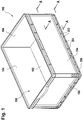
- FIG. 1 shows in a perspective view of a plastic container 100 for transporting and storing piece goods with bottom 102 and side walls 104 which senkkenkt stand up on the floor 102.
- a receiving area 105 of the container is defined, in which the cargo can be received.
- FIG. 1 Pockets 202 which are open to the outside of the container.
- the pockets are formed by the bottom 102 and a tread 200 of the container 100.
- Ribs 204 connect the bottom 102 with the tread 200.
- the container 100 can be placed with its tread 200 on a surface.
- the surface may be transport rollers of a roller conveyor.
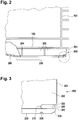
- the bottom 102 bends slightly due to the concave shape of the portion 206 down.
- FIG. 3 is shown in an enlarged view of the outside 208 facing edge region of the tread 200.
- the tread 200 has at its outer region, seen in the plane of the tread, a recess 300 open towards the outside 208 of the container.
- the recess has a bottom side 304 and an upper side 302 facing the receiving region of the container.
- the bottom side 304 is resiliently formed with respect to the upper side 302.
- the groove 308 is V-shaped.
- the tip of the V-shape in this case has the limitation indicated by reference numeral 310.
- the boundary is formed by one of the ribs 202.
- the recess 300 is a recess which has been formed in the rib 202.
- the element labeled 310 is thus a rounded bounding wall formed by the rib 202.
- the thickness of the bottom side 304 in the region of the recess 300 decreases continuously in the direction of the outside 208 of the container.
- the bottom side 306 is rounded off on the front side toward the outside 208.
- FIG. 4 shows a perspective view of the relative to the Figures 1 - 3 discussed container 100, which is even more clearly seen how the recess 300 is realized by a material recess on the ribs 204.
- the ribs 204 are thus not pulled through to the outer edge of the tread 200, but in this area material of the ribs 204 is recessed.
- FIG. 5 shows the container 100 in a plan view of the floor from below.
- the ribs 204 which are not normally visible in this view, have been shown schematically for the sake of completeness, which in reality are covered by the tread 200.
- a set of pockets 202 is formed by the bottom 102 and by the tread 200 and by the ribs 200 set at 45 ° to the outer walls.
- the ribs 204 extend diagonally in each quadrant of the container bottom.
- the ribs of adjacent quadrants meet one another only in sectional lines, which in each case bisect the container bottom in the longitudinal and transverse sides.
- FIG. 5 Further apparent in the FIG. 5 is the schematically illustrated groove 308, which extends continuously parallel to the outer sides of the container on the tread. It can be seen in FIG. 5 a rib bottom 402, which is adapted to the in FIG. 2 discussed bevel 20fi the bottom of the tank in the central area to realize. The ribs 400 of this ribbed bottom 402 run perpendicular to the outer sides of the container.
- the inclined ribs 204 serve primarily to reduce the running noise of the container via a roller conveyor
- the ribs 400 placed perpendicular to the outer walls serve to optimally transfer load from the container resting on the floor 102 to the cradle 200. Overall, this is generally the case spoke two different rib geometries for the central ribbed bottom and the adjoining pockets of the container used.
- the edge region 500 and 502 at the transition between the ribbed bottom 402 and tread on a crowning wherein the crown extends completely around the ribbed bottom.
- the container has a rectangular shape, wherein due to the crowning, the rib bottom is stretched more in the longitudinal direction of the container bottom than in the transverse direction of the container bottom, with the longitudinally extending crown 502 (bulge) being different from the transversely extending crown 500.
- the crowning of the circumferential edge region of the ribbed bottom is stretched in the direction of the container outer sides. Now acts a force from the receiving area of the container to the container bottom, this force often leads to a stretching deformation of the container bottom.
- the floor thus "warps" in the direction perpendicular to the floor surface.
- the deformation has a shape that resembles an elongated ellipsoid of revolution.
- the shape of the ellipsoid projected onto the floor is modeled.
- the ribbed bottom 402 will have a supporting rib structure there, where deformation of the soil is most likely to be expected.
- FIG. 6 an alternative variant is shown in which the pockets 202 are kept unchanged below the bottom together with the ribs 204 in the outer region of the container. Instead, a special tread 200 was chosen, now the tread 200 itself has the said recess 300. In this case, due to the recess 300, said bottom side 304 and said upper side 302 are created in the tread 300.
- the recess 300 is further subdivided by different webs not shown in detail. Although it could be weakened in the region of the webs, the spring action of the tread. However, the overall stability of the container is increased overall by the provision of the webs.
- FIG. 7 shows a perspective view of a container obliquely from below. Visible first is the tread 200, in turn, the located on the edge recess 308 can be seen. Likewise, the ribbed bottom 402 can be seen.
- the tread 200 has an inner rim 704 surrounding the rib bottom 402, an outer rim 700 surrounding the inner rim, and a middle rim 702 disposed between the inner rim 704 and the outer rim 700, the middle rim 702 completely surrounding the inner rim 704 ,
- the central rim 702 at least partially forms a first tread for the container since the first tread is elevated from the inner rim 704 and the outer rim 700.
- both the inner rim 704 and the outer rim 702 are bevelled so that they have a continuous slope in the direction of the central rim 702.
- the distance difference between the surface of the inner rim 704 and the surface of the first tread from the rib bottom 402 decreases steadily.
- the difference in the distance between the surface of the outer rim 700 and the surface of the first tread from the outer rim to the running surface decreases steadily.
- a conveyor roller would extend in the direction 710 and the container 100 were moved to the left on such a conveyor roller, initially a very small part of the surface of the outer rim would slowly and steadily run onto the conveyor roller. The container would slide smoothly on the roller, which is further damped by the spring action of the edge (recess 300).
- a second tread 706 and a third tread 708 is provided, wherein the second tread 706 is guided from the outer corners of the outer rim 700 to the central rim 702, wherein the second tread 706 relative to the inner rim 704 and the outer rim 700 is increased.
- the increase in the second running surface 706 also increases steadily from the outer edge of the container to the middle rim 702.
- third running surface 708 which is raised in relation to the inner rim 704 and the outer rim 700.
- the increase of the third running surface 708 also increases steadily from the outer container edge to the middle rim 702.
- the distance "d" between the central rim 702 and the fin bottom 402 will be minimized as compared to the edge regions at which the two crowns 500, 502 intersect.
- the slope of the inner rim 704 towards the central rim 702 is maximum.
Landscapes
- Engineering & Computer Science (AREA)
- Ceramic Engineering (AREA)
- Mechanical Engineering (AREA)
- Containers Having Bodies Formed In One Piece (AREA)
- Details Of Rigid Or Semi-Rigid Containers (AREA)
Priority Applications (1)
| Application Number | Priority Date | Filing Date | Title |
|---|---|---|---|
| PL14166627T PL2799355T3 (pl) | 2013-04-30 | 2014-04-30 | Pojemnik z tworzywa sztucznego |
Applications Claiming Priority (1)
| Application Number | Priority Date | Filing Date | Title |
|---|---|---|---|
| DE102013207943.5A DE102013207943B4 (de) | 2013-04-30 | 2013-04-30 | Kunststoffbehälter |
Publications (3)
| Publication Number | Publication Date |
|---|---|
| EP2799355A2 EP2799355A2 (de) | 2014-11-05 |
| EP2799355A3 EP2799355A3 (de) | 2015-02-25 |
| EP2799355B1 true EP2799355B1 (de) | 2017-11-22 |
Family
ID=50630646
Family Applications (1)
| Application Number | Title | Priority Date | Filing Date |
|---|---|---|---|
| EP14166627.1A Active EP2799355B1 (de) | 2013-04-30 | 2014-04-30 | Kunststoffbehälter |
Country Status (4)
| Country | Link |
|---|---|
| EP (1) | EP2799355B1 (pl) |
| DE (1) | DE102013207943B4 (pl) |
| ES (1) | ES2654310T3 (pl) |
| PL (1) | PL2799355T3 (pl) |
Cited By (1)
| Publication number | Priority date | Publication date | Assignee | Title |
|---|---|---|---|---|
| WO2024225710A1 (ko) * | 2023-04-27 | 2024-10-31 | 주식회사 엘지에너지솔루션 | 배터리 이송 트레이 |
Families Citing this family (8)
| Publication number | Priority date | Publication date | Assignee | Title |
|---|---|---|---|---|
| DE102016124041B3 (de) | 2016-12-12 | 2018-03-01 | Bito-Lagertechnik Bittmann Gmbh | Kunststoffbehälter |
| GB2560405B (en) * | 2017-01-09 | 2020-05-27 | Loadhog Ltd | Container and lid |
| ES2911802T3 (es) | 2019-05-07 | 2022-05-20 | Schoeller Allibert Gmbh | Recipiente con placa de soporte con salientes |
| CH717725A1 (de) * | 2020-08-10 | 2022-02-15 | Utz Georg Holding Ag | Kunststoffbehälter. |
| DE102020128601B3 (de) | 2020-10-30 | 2021-12-02 | Gebhardt Fördertechnik GmbH | Kunststoffbehältnis |
| AT525702A1 (de) * | 2021-12-02 | 2023-06-15 | Tgw Logistics Group Gmbh | Tablar zum Transport eines Ladeguts in einem Kommissioniersystem, Entladevorrichtung und Beladevorrichtung |
| DE102023116648A1 (de) | 2023-06-23 | 2024-12-24 | Bito-Lagertechnik Bittmann Gmbh | Behälter mit einer über dem Boden freischwebenden Stoßzunge |
| DE102023116647A1 (de) | 2023-06-23 | 2024-12-24 | Bito-Lagertechnik Bittmann Gmbh | Behälter mit einem Rücksprung an einer Seitenwand zum Einbringen eines Rückholarms einer Rückholvorrichtung zum Ziehen des Behälters |
Family Cites Families (7)
| Publication number | Priority date | Publication date | Assignee | Title |
|---|---|---|---|---|
| DE4006188C1 (en) * | 1990-02-28 | 1991-07-25 | Stucki Kunststoffwerk Und Werkzeugbau Gmbh, 4902 Bad Salzuflen, De | Plastic transport crate with ribbed base - has false bottom with upwards inclined section at crate centre facing edge |
| DE4411647A1 (de) * | 1994-04-02 | 1995-10-05 | Stucki Kunststoffwerk | Im Kreuzstapelverbund stapelbarer Transportbehälter |
| DE19844015B4 (de) * | 1998-09-25 | 2004-06-17 | Linpac Stucki Kunststoffverarbeitung Gmbh | Einstückig aus Kunststoff hergestellter Transportkasten |
| DE19844014C1 (de) * | 1998-09-25 | 2000-01-20 | Linpac Stucki Kunststoffverarb | Einstückig aus Kunststoff hergestellter Transportkasten |
| DE29908668U1 (de) * | 1999-05-17 | 2000-08-03 | Fritz Schäfer GmbH, 57290 Neunkirchen | Transportkasten aus Kunststoff |
| DE20315302U1 (de) * | 2003-10-01 | 2004-02-12 | Fritz Schäfer GmbH | Einstückig durch Verschweißen hergestellter Behälter aus Kunststoff |
| DE102010013864A1 (de) * | 2010-04-01 | 2012-09-06 | Georg Utz Holding Ag | Kunststoffbehälter zum Transport und zur Lagerung von Gütern |
-
2013
- 2013-04-30 DE DE102013207943.5A patent/DE102013207943B4/de active Active
-
2014
- 2014-04-30 PL PL14166627T patent/PL2799355T3/pl unknown
- 2014-04-30 ES ES14166627.1T patent/ES2654310T3/es active Active
- 2014-04-30 EP EP14166627.1A patent/EP2799355B1/de active Active
Non-Patent Citations (1)
| Title |
|---|
| None * |
Cited By (1)
| Publication number | Priority date | Publication date | Assignee | Title |
|---|---|---|---|---|
| WO2024225710A1 (ko) * | 2023-04-27 | 2024-10-31 | 주식회사 엘지에너지솔루션 | 배터리 이송 트레이 |
Also Published As
| Publication number | Publication date |
|---|---|
| EP2799355A2 (de) | 2014-11-05 |
| DE102013207943A1 (de) | 2014-10-30 |
| DE102013207943B4 (de) | 2014-11-13 |
| PL2799355T3 (pl) | 2018-03-30 |
| EP2799355A3 (de) | 2015-02-25 |
| ES2654310T3 (es) | 2018-02-13 |
Similar Documents
| Publication | Publication Date | Title |
|---|---|---|
| EP2799355B1 (de) | Kunststoffbehälter | |
| EP2878549B1 (de) | Palette | |
| DE69103699T2 (de) | Kasten zur Aufnahme von Flaschen. | |
| EP3099589B1 (de) | Stapelbarer kunststoffbehaelter | |
| AT521362B1 (de) | Stapelbare Kiste | |
| EP3333093B1 (de) | Kunststoffbehälter | |
| EP0536462A1 (de) | Kastenförmiger Behälter aus Kunststoff | |
| EP2799356B1 (de) | Kunststoffbehälter | |
| EP2722285B1 (de) | Kunststoffpalette mit Versteifungselement | |
| WO2007137774A1 (de) | Systemkiste insbesondere für den transport von frischem fisch | |
| EP2643247B1 (de) | Führungselement für transportketten sowie förder- und/oder speichereinrichtung mit solchen führungselementen | |
| EP2735520B1 (de) | Schließelemente für das Griffloch eines Behälters | |
| EP2767483B1 (de) | Stapelbarer Transportbehälter | |
| AT510852B1 (de) | Kunststoffbehälter, insbesondere flaschenkasten | |
| EP3626646B1 (de) | Stapelbare kiste | |
| EP3131834A1 (de) | Mülltonne mit einem spritzgegossenen kunststoffkörper | |
| EP0989063A1 (de) | Einstückig aus Kunststoff hergestellter Transportkasten | |
| EP3409605A1 (de) | Kiste, insbesondere zur lagerung und/oder zum transport von geschirr | |
| EP3131836B1 (de) | Mülltonne mit einem spritzgegossenen kunststoffkörper | |
| DE102006017363B4 (de) | Stirnwand für eine Wickelgutrolle und Anordnung von Stirnwänden | |
| WO2016131523A1 (de) | Kasten aus kunststoff, insbesondere flaschenkasten | |
| DE202021103561U1 (de) | Stapelbare Box | |
| EP1375292A1 (de) | Seitenrahmen einer Palette und Palettenanordnung | |
| EP3263472A1 (de) | Verpackung |
Legal Events
| Date | Code | Title | Description |
|---|---|---|---|
| PUAI | Public reference made under article 153(3) epc to a published international application that has entered the european phase |
Free format text: ORIGINAL CODE: 0009012 |
|
| 17P | Request for examination filed |
Effective date: 20140430 |
|
| AK | Designated contracting states |
Kind code of ref document: A2 Designated state(s): AL AT BE BG CH CY CZ DE DK EE ES FI FR GB GR HR HU IE IS IT LI LT LU LV MC MK MT NL NO PL PT RO RS SE SI SK SM TR |
|
| AX | Request for extension of the european patent |
Extension state: BA ME |
|
| PUAL | Search report despatched |
Free format text: ORIGINAL CODE: 0009013 |
|
| AK | Designated contracting states |
Kind code of ref document: A3 Designated state(s): AL AT BE BG CH CY CZ DE DK EE ES FI FR GB GR HR HU IE IS IT LI LT LU LV MC MK MT NL NO PL PT RO RS SE SI SK SM TR |
|
| AX | Request for extension of the european patent |
Extension state: BA ME |
|
| RIC1 | Information provided on ipc code assigned before grant |
Ipc: B65D 1/22 20060101AFI20150121BHEP |
|
| R17P | Request for examination filed (corrected) |
Effective date: 20150708 |
|
| RBV | Designated contracting states (corrected) |
Designated state(s): AL AT BE BG CH CY CZ DE DK EE ES FI FR GB GR HR HU IE IS IT LI LT LU LV MC MK MT NL NO PL PT RO RS SE SI SK SM TR |
|
| 17Q | First examination report despatched |
Effective date: 20161021 |
|
| GRAP | Despatch of communication of intention to grant a patent |
Free format text: ORIGINAL CODE: EPIDOSNIGR1 |
|
| INTG | Intention to grant announced |
Effective date: 20170830 |
|
| GRAS | Grant fee paid |
Free format text: ORIGINAL CODE: EPIDOSNIGR3 |
|
| GRAA | (expected) grant |
Free format text: ORIGINAL CODE: 0009210 |
|
| AK | Designated contracting states |
Kind code of ref document: B1 Designated state(s): AL AT BE BG CH CY CZ DE DK EE ES FI FR GB GR HR HU IE IS IT LI LT LU LV MC MK MT NL NO PL PT RO RS SE SI SK SM TR |
|
| REG | Reference to a national code |
Ref country code: GB Ref legal event code: FG4D Free format text: NOT ENGLISH |
|
| REG | Reference to a national code |
Ref country code: CH Ref legal event code: EP |
|
| REG | Reference to a national code |
Ref country code: IE Ref legal event code: FG4D Free format text: LANGUAGE OF EP DOCUMENT: GERMAN |
|
| REG | Reference to a national code |
Ref country code: AT Ref legal event code: REF Ref document number: 948147 Country of ref document: AT Kind code of ref document: T Effective date: 20171215 |
|
| REG | Reference to a national code |
Ref country code: DE Ref legal event code: R096 Ref document number: 502014006299 Country of ref document: DE |
|
| REG | Reference to a national code |
Ref country code: NL Ref legal event code: FP |
|
| REG | Reference to a national code |
Ref country code: ES Ref legal event code: FG2A Ref document number: 2654310 Country of ref document: ES Kind code of ref document: T3 Effective date: 20180213 |
|
| REG | Reference to a national code |
Ref country code: LT Ref legal event code: MG4D |
|
| REG | Reference to a national code |
Ref country code: FR Ref legal event code: PLFP Year of fee payment: 5 |
|
| PG25 | Lapsed in a contracting state [announced via postgrant information from national office to epo] |
Ref country code: LT Free format text: LAPSE BECAUSE OF FAILURE TO SUBMIT A TRANSLATION OF THE DESCRIPTION OR TO PAY THE FEE WITHIN THE PRESCRIBED TIME-LIMIT Effective date: 20171122 Ref country code: SE Free format text: LAPSE BECAUSE OF FAILURE TO SUBMIT A TRANSLATION OF THE DESCRIPTION OR TO PAY THE FEE WITHIN THE PRESCRIBED TIME-LIMIT Effective date: 20171122 Ref country code: NO Free format text: LAPSE BECAUSE OF FAILURE TO SUBMIT A TRANSLATION OF THE DESCRIPTION OR TO PAY THE FEE WITHIN THE PRESCRIBED TIME-LIMIT Effective date: 20180222 Ref country code: FI Free format text: LAPSE BECAUSE OF FAILURE TO SUBMIT A TRANSLATION OF THE DESCRIPTION OR TO PAY THE FEE WITHIN THE PRESCRIBED TIME-LIMIT Effective date: 20171122 |
|
| PG25 | Lapsed in a contracting state [announced via postgrant information from national office to epo] |
Ref country code: RS Free format text: LAPSE BECAUSE OF FAILURE TO SUBMIT A TRANSLATION OF THE DESCRIPTION OR TO PAY THE FEE WITHIN THE PRESCRIBED TIME-LIMIT Effective date: 20171122 Ref country code: LV Free format text: LAPSE BECAUSE OF FAILURE TO SUBMIT A TRANSLATION OF THE DESCRIPTION OR TO PAY THE FEE WITHIN THE PRESCRIBED TIME-LIMIT Effective date: 20171122 Ref country code: BG Free format text: LAPSE BECAUSE OF FAILURE TO SUBMIT A TRANSLATION OF THE DESCRIPTION OR TO PAY THE FEE WITHIN THE PRESCRIBED TIME-LIMIT Effective date: 20180222 Ref country code: HR Free format text: LAPSE BECAUSE OF FAILURE TO SUBMIT A TRANSLATION OF THE DESCRIPTION OR TO PAY THE FEE WITHIN THE PRESCRIBED TIME-LIMIT Effective date: 20171122 Ref country code: GR Free format text: LAPSE BECAUSE OF FAILURE TO SUBMIT A TRANSLATION OF THE DESCRIPTION OR TO PAY THE FEE WITHIN THE PRESCRIBED TIME-LIMIT Effective date: 20180223 |
|
| PG25 | Lapsed in a contracting state [announced via postgrant information from national office to epo] |
Ref country code: CY Free format text: LAPSE BECAUSE OF FAILURE TO SUBMIT A TRANSLATION OF THE DESCRIPTION OR TO PAY THE FEE WITHIN THE PRESCRIBED TIME-LIMIT Effective date: 20171122 Ref country code: CZ Free format text: LAPSE BECAUSE OF FAILURE TO SUBMIT A TRANSLATION OF THE DESCRIPTION OR TO PAY THE FEE WITHIN THE PRESCRIBED TIME-LIMIT Effective date: 20171122 Ref country code: EE Free format text: LAPSE BECAUSE OF FAILURE TO SUBMIT A TRANSLATION OF THE DESCRIPTION OR TO PAY THE FEE WITHIN THE PRESCRIBED TIME-LIMIT Effective date: 20171122 Ref country code: DK Free format text: LAPSE BECAUSE OF FAILURE TO SUBMIT A TRANSLATION OF THE DESCRIPTION OR TO PAY THE FEE WITHIN THE PRESCRIBED TIME-LIMIT Effective date: 20171122 Ref country code: SK Free format text: LAPSE BECAUSE OF FAILURE TO SUBMIT A TRANSLATION OF THE DESCRIPTION OR TO PAY THE FEE WITHIN THE PRESCRIBED TIME-LIMIT Effective date: 20171122 |
|
| REG | Reference to a national code |
Ref country code: DE Ref legal event code: R097 Ref document number: 502014006299 Country of ref document: DE |
|
| PG25 | Lapsed in a contracting state [announced via postgrant information from national office to epo] |
Ref country code: RO Free format text: LAPSE BECAUSE OF FAILURE TO SUBMIT A TRANSLATION OF THE DESCRIPTION OR TO PAY THE FEE WITHIN THE PRESCRIBED TIME-LIMIT Effective date: 20171122 Ref country code: SM Free format text: LAPSE BECAUSE OF FAILURE TO SUBMIT A TRANSLATION OF THE DESCRIPTION OR TO PAY THE FEE WITHIN THE PRESCRIBED TIME-LIMIT Effective date: 20171122 |
|
| PG25 | Lapsed in a contracting state [announced via postgrant information from national office to epo] |
Ref country code: MT Free format text: LAPSE BECAUSE OF FAILURE TO SUBMIT A TRANSLATION OF THE DESCRIPTION OR TO PAY THE FEE WITHIN THE PRESCRIBED TIME-LIMIT Effective date: 20171122 |
|
| PLBE | No opposition filed within time limit |
Free format text: ORIGINAL CODE: 0009261 |
|
| STAA | Information on the status of an ep patent application or granted ep patent |
Free format text: STATUS: NO OPPOSITION FILED WITHIN TIME LIMIT |
|
| 26N | No opposition filed |
Effective date: 20180823 |
|
| PG25 | Lapsed in a contracting state [announced via postgrant information from national office to epo] |
Ref country code: SI Free format text: LAPSE BECAUSE OF FAILURE TO SUBMIT A TRANSLATION OF THE DESCRIPTION OR TO PAY THE FEE WITHIN THE PRESCRIBED TIME-LIMIT Effective date: 20171122 Ref country code: MC Free format text: LAPSE BECAUSE OF FAILURE TO SUBMIT A TRANSLATION OF THE DESCRIPTION OR TO PAY THE FEE WITHIN THE PRESCRIBED TIME-LIMIT Effective date: 20171122 |
|
| REG | Reference to a national code |
Ref country code: IE Ref legal event code: MM4A |
|
| PG25 | Lapsed in a contracting state [announced via postgrant information from national office to epo] |
Ref country code: LU Free format text: LAPSE BECAUSE OF NON-PAYMENT OF DUE FEES Effective date: 20180430 |
|
| PG25 | Lapsed in a contracting state [announced via postgrant information from national office to epo] |
Ref country code: IE Free format text: LAPSE BECAUSE OF NON-PAYMENT OF DUE FEES Effective date: 20180430 |
|
| PG25 | Lapsed in a contracting state [announced via postgrant information from national office to epo] |
Ref country code: TR Free format text: LAPSE BECAUSE OF FAILURE TO SUBMIT A TRANSLATION OF THE DESCRIPTION OR TO PAY THE FEE WITHIN THE PRESCRIBED TIME-LIMIT Effective date: 20171122 |
|
| PG25 | Lapsed in a contracting state [announced via postgrant information from national office to epo] |
Ref country code: PT Free format text: LAPSE BECAUSE OF FAILURE TO SUBMIT A TRANSLATION OF THE DESCRIPTION OR TO PAY THE FEE WITHIN THE PRESCRIBED TIME-LIMIT Effective date: 20171122 Ref country code: HU Free format text: LAPSE BECAUSE OF FAILURE TO SUBMIT A TRANSLATION OF THE DESCRIPTION OR TO PAY THE FEE WITHIN THE PRESCRIBED TIME-LIMIT; INVALID AB INITIO Effective date: 20140430 |
|
| PG25 | Lapsed in a contracting state [announced via postgrant information from national office to epo] |
Ref country code: MK Free format text: LAPSE BECAUSE OF NON-PAYMENT OF DUE FEES Effective date: 20171122 |
|
| PG25 | Lapsed in a contracting state [announced via postgrant information from national office to epo] |
Ref country code: AL Free format text: LAPSE BECAUSE OF FAILURE TO SUBMIT A TRANSLATION OF THE DESCRIPTION OR TO PAY THE FEE WITHIN THE PRESCRIBED TIME-LIMIT Effective date: 20171122 Ref country code: IS Free format text: LAPSE BECAUSE OF FAILURE TO SUBMIT A TRANSLATION OF THE DESCRIPTION OR TO PAY THE FEE WITHIN THE PRESCRIBED TIME-LIMIT Effective date: 20180322 |
|
| PGFP | Annual fee paid to national office [announced via postgrant information from national office to epo] |
Ref country code: NL Payment date: 20240418 Year of fee payment: 11 |
|
| PGFP | Annual fee paid to national office [announced via postgrant information from national office to epo] |
Ref country code: ES Payment date: 20240524 Year of fee payment: 11 |
|
| PGFP | Annual fee paid to national office [announced via postgrant information from national office to epo] |
Ref country code: AT Payment date: 20240419 Year of fee payment: 11 |
|
| PGFP | Annual fee paid to national office [announced via postgrant information from national office to epo] |
Ref country code: IT Payment date: 20240424 Year of fee payment: 11 Ref country code: FR Payment date: 20240425 Year of fee payment: 11 |
|
| PGFP | Annual fee paid to national office [announced via postgrant information from national office to epo] |
Ref country code: BE Payment date: 20240418 Year of fee payment: 11 |
|
| PGFP | Annual fee paid to national office [announced via postgrant information from national office to epo] |
Ref country code: PL Payment date: 20250418 Year of fee payment: 12 Ref country code: DE Payment date: 20250422 Year of fee payment: 12 |
|
| PGFP | Annual fee paid to national office [announced via postgrant information from national office to epo] |
Ref country code: GB Payment date: 20250423 Year of fee payment: 12 |
|
| PGFP | Annual fee paid to national office [announced via postgrant information from national office to epo] |
Ref country code: CH Payment date: 20250501 Year of fee payment: 12 |
|
| REG | Reference to a national code |
Ref country code: NL Ref legal event code: MM Effective date: 20250501 |
|
| REG | Reference to a national code |
Ref country code: AT Ref legal event code: MM01 Ref document number: 948147 Country of ref document: AT Kind code of ref document: T Effective date: 20250430 |
|
| REG | Reference to a national code |
Ref country code: BE Ref legal event code: MM Effective date: 20250430 |
|
| PG25 | Lapsed in a contracting state [announced via postgrant information from national office to epo] |
Ref country code: AT Free format text: LAPSE BECAUSE OF NON-PAYMENT OF DUE FEES Effective date: 20250430 |
|
| PG25 | Lapsed in a contracting state [announced via postgrant information from national office to epo] |
Ref country code: NL Free format text: LAPSE BECAUSE OF NON-PAYMENT OF DUE FEES Effective date: 20250501 Ref country code: FR Free format text: LAPSE BECAUSE OF NON-PAYMENT OF DUE FEES Effective date: 20250430 |
|
| PG25 | Lapsed in a contracting state [announced via postgrant information from national office to epo] |
Ref country code: BE Free format text: LAPSE BECAUSE OF NON-PAYMENT OF DUE FEES Effective date: 20250430 |