EP2799355B1 - Plastic container - Google Patents
Plastic container Download PDFInfo
- Publication number
- EP2799355B1 EP2799355B1 EP14166627.1A EP14166627A EP2799355B1 EP 2799355 B1 EP2799355 B1 EP 2799355B1 EP 14166627 A EP14166627 A EP 14166627A EP 2799355 B1 EP2799355 B1 EP 2799355B1
- Authority
- EP
- European Patent Office
- Prior art keywords
- container
- rim
- contact face
- base
- plastic container
- Prior art date
- Legal status (The legal status is an assumption and is not a legal conclusion. Google has not performed a legal analysis and makes no representation as to the accuracy of the status listed.)
- Active
Links
Images


Classifications
-
- B—PERFORMING OPERATIONS; TRANSPORTING
- B65—CONVEYING; PACKING; STORING; HANDLING THIN OR FILAMENTARY MATERIAL
- B65D—CONTAINERS FOR STORAGE OR TRANSPORT OF ARTICLES OR MATERIALS, e.g. BAGS, BARRELS, BOTTLES, BOXES, CANS, CARTONS, CRATES, DRUMS, JARS, TANKS, HOPPERS, FORWARDING CONTAINERS; ACCESSORIES, CLOSURES, OR FITTINGS THEREFOR; PACKAGING ELEMENTS; PACKAGES
- B65D1/00—Containers having bodies formed in one piece, e.g. by casting metallic material, by moulding plastics, by blowing vitreous material, by throwing ceramic material, by moulding pulped fibrous material, by deep-drawing operations performed on sheet material
- B65D1/22—Boxes or like containers with side walls of substantial depth for enclosing contents
Definitions
- the invention relates to a plastic container with tread.
- the DE 198 44 014 C1 describes a transport box made in one piece from plastic according to the preamble of claim 1, with a level in the middle region of the box bottom under which at least two parallel runners are in the edge region of the box, which are connected by transverse to the runners ribs with the bottom in that pockets which are open towards the outside and / or inside by the runners, the transverse ribs and the bottom bottom surface are formed, and in which the runners on the side facing the center of the box have a longitudinal section which is directed upwards.
- the WO 2011/120641 A1 describes a box-shaped plastic container for the transport and storage of goods with a grid-like webs reinforced bottom and ascending from this bottom side walls, wherein at least on the webs in the region of the bottom a reinforcing plate made of plastic is applied and fixed, which is characterized in that in the plastic of the reinforcing plate reinforcing fibers are pressed.
- the DE 203 15 302 U1 describes a plastic container manufactured in one piece by welding, in particular storage and transport box, which is provided on the lower surface of its bottom with ribs forming a Bodenffenfeld, and circumferentially along the bottom edge of an outer tread providing flat webs as a double bottom.
- the invention has for its object to provide an improved transport and storage container made of plastic.
- running rim is understood to mean that surface of the container with which the container at least partially rests on a floor surface.
- surface "Auffier Scheme” When rolling over a roller conveyor of the tread is the surface "Auffier Scheme", with which the plastic container runs onto the rollers of the roller conveyor and then gets into contact with the transport rollers of the roller conveyor.
- Embodiments of the invention could have the advantage of minimizing noise during sliding of the plastic container over the rollers of the roller conveyor. By increasing the middle ring, the contact surface becomes minimized, with the softer the container is in contact with the rollers of the roller conveyor.
- the first running surface is rounded at its sides facing the inner rim and / or the outer rim towards the receiving area of the container. This could have the advantage that the first tread of the middle ring does not run abruptly but steadily, evenly and gently onto a transport roller. This smoother rolling will minimize the noise associated with rolling up.
- Another advantage could be that vibrations of the plastic container are minimized by the softer curling. This makes it possible to transport such cargo in the plastic container, which is sensitive to shocks. These could be, for example, optical measuring instruments.
- the floor further comprises a second tread, wherein the second tread is guided from the outer corners of the outer rim to the first tread, wherein the second tread is increased relative to the inner rim and the outer rim.
- the outer ring is completely interrupted by the second tread several times.
- the increase of the second tread is identical to the increase of the first tread.
- the second tread may be rounded at its outer edge towards the receiving area of the container.
- the floor further comprises a third tread, wherein the third tread is guided perpendicular to the outside of the container from the outer edge of the outer rim to the first tread, wherein the third tread is increased relative to the inner rim and the outer rim.
- the increase of the third tread is e.g. identical to the increase in the first tread. Further, e.g. the third tread rounded at its outer edge towards the receiving area of the container. This could have the advantage that even when carrying high loads in the container interior, the emergence of the container bottom on transport rollers remains gentle.
- the container bottom could in particular asymmetrically bend down in the region of the container edge, nevertheless a gentle emergence is guaranteed even in the sagged area at the container edge by the additional "emergence aid" in the form of the third tread.
- the third running surface could thus ensure that a highly uniform loading edge of the container bottom is ensured under high load on the container bottom.
- the inner region towards the inner rim seen in the plane of the container bottom has a crowning, wherein the crown extends completely around the inner region.
- the crowning can simulate the hypothetical deformation of the bottom. In particular, in a rectangular shape of the container, this hypothetical deformation of the bottom will have a kind of oval shape when projected onto the plane of extension of the container bottom.
- the inner region is stretched more in the longitudinal direction of the container bottom than in the transverse direction of the container bottom, with the longitudinally extending crown differing from the transversely extending crown, it could be ensured that there is optimum space for deformation to take place Container bottom is created.
- the space available for the deformation is thus almost proportional to the expected spatial deformation of the soil.
- the interior of the floor is a ribbed floor.
- the ribs of the ribbed bottom could run perpendicular to the outer sides of the container, whereby in particular a power transmission from the container center to the container outer sides can be optimized.
- the ribbed bottom thus leads to an unintended bending of the soil in the region of the ribbed bottom is reduced.
- the ribbed bottom is additionally concave, that is curved in the direction of the container interior. This also helps to increase the carrying capacity of the container when loading at high loads. Forces acting on the bottom of the tank are transmitted evenly outwards towards the outer walls on the tread.
- the first tread and / or the second tread and / or the third tread are formed integrally with each other.
- the material of the first tread and the second tread is softer compared to the material of the inner rim and / or the outer rim. This makes it possible to optimize the noise characteristics when overflowing the tread over a roller conveyor in an efficient manner. With respect to the bottom and the rest of the container, however, a material could be selected, which is particularly impact resistant and stable.
- the outer rim has at its seen in the plane of the bottom outer region to the outside of the container open recess, the recess has a bottom side and a wall facing the receiving area top side, wherein the bottom side opposite the top resiliently formed is.
- Another advantage could be that vibrations of the plastic container are minimized by the softer curling. This makes it possible to transport such cargo in the plastic container, which is sensitive to shocks. These could be, for example, optical measuring instruments.
- the recess extends around the entire outside of the container. Thus, it does not matter in which direction the plastic container slides over the rollers of the roller conveyor. In every orientation there is a minimization of noise during sliding over.
- the recess is divided into a plurality of chambers by webs.
- the recess extends continuously around the entire outside of the container. While the latter has the advantage that the resilient properties of the recess can be better utilized, dividing the recess into a plurality of chambers by means of webs could have the advantage that the stability of the recess is increased. In particular, this could avoid that the region of the recess breaks off from the edge of the container.
- the plastic container further comprises a groove extending on the rear side of the bottom side of the recess, the groove extending parallel to the outside of the container towards which the recess is open.
- the groove may be straight or serpentine or zigzag parallel to the outside of the container. The extension direction of the groove is thus parallel to the outside of the container.
- the groove runs parallel to the associated outside around the entire container.
- the use of a groove could have the advantage that the resilient properties of the bake area of the container can be further optimized. For example, a very impact-resistant plastic could be used as the tread, which has only low resilient properties.
- the groove is V-shaped, the recess terminating in a bounding wall with the tip of the groove facing the wall.
- the recess thus has in this case the said upper side, the bottom side, wherein the bottom side and the upper side are connected to each other by this limiting wall.
- the thickness of the bottom side decreases in the region of the recess in the direction of the outside of the container.
- the decrease in the thickness of the bottom side which is preferably continuous, results in a very smooth start-up and thus a continuous increase in the spring force. This leads to the noise being further minimized.
- the bottom side is rounded at its outer edge facing the outside of the container. This also serves to optimize the emergence of the outer edge on a roller of a roller conveyor. An abrupt and thus noise developing emergence is avoided.
- the recess ends by said limiting wall, wherein the wall itself is also rounded.
- the rounding of the wall further allows to precisely adjust the resilient properties of the bake area. By rounding off, however, the mechanical stability of the connection of the region of the recess is increased to the rest of the floor. There are no force peaks due to the rounding, so that the risk of breakage of the resulting by the recess run-area is minimized.
- the bottom side opposite the top is so resiliently designed to reduce a running noise of the container on a roller conveyor when the tread moves over the roller conveyors.
- the bottom has open pockets towards the outside of the container, the pockets passing through the bottom and the bottom Laufranz are formed, wherein the pockets are formed by the bottom and the tread ribs connecting. This could allow low cost of materials cost-effective production of the container in an injection molding process. So it is not required solid material from which out the recess is formed.
- the ribs forming the pockets run obliquely to the outer sides of the container. Since transport boxes are usually transported via roller conveyors aligned with at least one side wall parallel to the rollers, is ensured by the oblique arrangement of the pockets forming ribs that in most cases of transport of the plastic container via a roller conveyor, the majority of the ribs obliquely to the rollers is arranged.
- the container never rests with a rib parallel to a roll on the roll. This could avoid that, in particular, the container is in such a position for a long period of time, in which the container is located with the ribs in parallel between different roller conveyors.
- the ribs each come to rest so that they extend in the cavities between adjacent rollers parallel to these rollers. This could cause the area between the ribs to bend down towards the rollers. Even a slight deformation would be sufficient here, however, that in the case of a subsequent sliding of the container over the rollers due to the unevenness of the tread now present, a noise during overflow is increased. In this case, it could thus be prevented by inclined ribs that unintentional bending and thus shaking of the container when overflowing over the rollers.
- the inclined ribs in particular at an angle of 45 ° to the respective side walls thus also minimize the risk of noise when overflowing over a roller conveyor.
- the limiting wall is formed by the ribs forming the pockets, the upper side also being formed by the ribs forming the pockets. Since thus the recess is preferably present only in the ribs themselves, the further technical is hardly or not at all affected by the recess by providing the recesses.
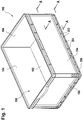
- FIG. 1 shows in a perspective view of a plastic container 100 for transporting and storing piece goods with bottom 102 and side walls 104 which senkkenkt stand up on the floor 102.
- a receiving area 105 of the container is defined, in which the cargo can be received.
- FIG. 1 Pockets 202 which are open to the outside of the container.
- the pockets are formed by the bottom 102 and a tread 200 of the container 100.
- Ribs 204 connect the bottom 102 with the tread 200.
- the container 100 can be placed with its tread 200 on a surface.
- the surface may be transport rollers of a roller conveyor.
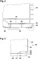
- the bottom 102 bends slightly due to the concave shape of the portion 206 down.
- FIG. 3 is shown in an enlarged view of the outside 208 facing edge region of the tread 200.
- the tread 200 has at its outer region, seen in the plane of the tread, a recess 300 open towards the outside 208 of the container.
- the recess has a bottom side 304 and an upper side 302 facing the receiving region of the container.
- the bottom side 304 is resiliently formed with respect to the upper side 302.
- the groove 308 is V-shaped.
- the tip of the V-shape in this case has the limitation indicated by reference numeral 310.
- the boundary is formed by one of the ribs 202.
- the recess 300 is a recess which has been formed in the rib 202.
- the element labeled 310 is thus a rounded bounding wall formed by the rib 202.
- the thickness of the bottom side 304 in the region of the recess 300 decreases continuously in the direction of the outside 208 of the container.
- the bottom side 306 is rounded off on the front side toward the outside 208.
- FIG. 4 shows a perspective view of the relative to the Figures 1 - 3 discussed container 100, which is even more clearly seen how the recess 300 is realized by a material recess on the ribs 204.
- the ribs 204 are thus not pulled through to the outer edge of the tread 200, but in this area material of the ribs 204 is recessed.
- FIG. 5 shows the container 100 in a plan view of the floor from below.
- the ribs 204 which are not normally visible in this view, have been shown schematically for the sake of completeness, which in reality are covered by the tread 200.
- a set of pockets 202 is formed by the bottom 102 and by the tread 200 and by the ribs 200 set at 45 ° to the outer walls.
- the ribs 204 extend diagonally in each quadrant of the container bottom.
- the ribs of adjacent quadrants meet one another only in sectional lines, which in each case bisect the container bottom in the longitudinal and transverse sides.
- FIG. 5 Further apparent in the FIG. 5 is the schematically illustrated groove 308, which extends continuously parallel to the outer sides of the container on the tread. It can be seen in FIG. 5 a rib bottom 402, which is adapted to the in FIG. 2 discussed bevel 20fi the bottom of the tank in the central area to realize. The ribs 400 of this ribbed bottom 402 run perpendicular to the outer sides of the container.
- the inclined ribs 204 serve primarily to reduce the running noise of the container via a roller conveyor
- the ribs 400 placed perpendicular to the outer walls serve to optimally transfer load from the container resting on the floor 102 to the cradle 200. Overall, this is generally the case spoke two different rib geometries for the central ribbed bottom and the adjoining pockets of the container used.
- the edge region 500 and 502 at the transition between the ribbed bottom 402 and tread on a crowning wherein the crown extends completely around the ribbed bottom.
- the container has a rectangular shape, wherein due to the crowning, the rib bottom is stretched more in the longitudinal direction of the container bottom than in the transverse direction of the container bottom, with the longitudinally extending crown 502 (bulge) being different from the transversely extending crown 500.
- the crowning of the circumferential edge region of the ribbed bottom is stretched in the direction of the container outer sides. Now acts a force from the receiving area of the container to the container bottom, this force often leads to a stretching deformation of the container bottom.
- the floor thus "warps" in the direction perpendicular to the floor surface.
- the deformation has a shape that resembles an elongated ellipsoid of revolution.
- the shape of the ellipsoid projected onto the floor is modeled.
- the ribbed bottom 402 will have a supporting rib structure there, where deformation of the soil is most likely to be expected.
- FIG. 6 an alternative variant is shown in which the pockets 202 are kept unchanged below the bottom together with the ribs 204 in the outer region of the container. Instead, a special tread 200 was chosen, now the tread 200 itself has the said recess 300. In this case, due to the recess 300, said bottom side 304 and said upper side 302 are created in the tread 300.
- the recess 300 is further subdivided by different webs not shown in detail. Although it could be weakened in the region of the webs, the spring action of the tread. However, the overall stability of the container is increased overall by the provision of the webs.
- FIG. 7 shows a perspective view of a container obliquely from below. Visible first is the tread 200, in turn, the located on the edge recess 308 can be seen. Likewise, the ribbed bottom 402 can be seen.
- the tread 200 has an inner rim 704 surrounding the rib bottom 402, an outer rim 700 surrounding the inner rim, and a middle rim 702 disposed between the inner rim 704 and the outer rim 700, the middle rim 702 completely surrounding the inner rim 704 ,
- the central rim 702 at least partially forms a first tread for the container since the first tread is elevated from the inner rim 704 and the outer rim 700.
- both the inner rim 704 and the outer rim 702 are bevelled so that they have a continuous slope in the direction of the central rim 702.
- the distance difference between the surface of the inner rim 704 and the surface of the first tread from the rib bottom 402 decreases steadily.
- the difference in the distance between the surface of the outer rim 700 and the surface of the first tread from the outer rim to the running surface decreases steadily.
- a conveyor roller would extend in the direction 710 and the container 100 were moved to the left on such a conveyor roller, initially a very small part of the surface of the outer rim would slowly and steadily run onto the conveyor roller. The container would slide smoothly on the roller, which is further damped by the spring action of the edge (recess 300).
- a second tread 706 and a third tread 708 is provided, wherein the second tread 706 is guided from the outer corners of the outer rim 700 to the central rim 702, wherein the second tread 706 relative to the inner rim 704 and the outer rim 700 is increased.
- the increase in the second running surface 706 also increases steadily from the outer edge of the container to the middle rim 702.
- third running surface 708 which is raised in relation to the inner rim 704 and the outer rim 700.
- the increase of the third running surface 708 also increases steadily from the outer container edge to the middle rim 702.
- the distance "d" between the central rim 702 and the fin bottom 402 will be minimized as compared to the edge regions at which the two crowns 500, 502 intersect.
- the slope of the inner rim 704 towards the central rim 702 is maximum.
Description
Die Erfindung betrifft einen Kunststoffbehälter mit Laufkranz.The invention relates to a plastic container with tread.
Aus dem Stand der Technik sind verschiedene Kunststoffbehälter bekannt. Beispielsweise beschreibt die
Die
Die
Die
Der Erfindung liegt die Aufgabe zugrunde, einen verbesserten Transport- und Lagerbehälter aus Kunststoff bereitzustellen.The invention has for its object to provide an improved transport and storage container made of plastic.
Die der Erfindung zugrunde liegende Aufgabe wird durch die Merkmale des unabhängigen Patentanspruchs gelöst. Bevorzugte Ausführungsformen der Erfindung sind in den abhängigen Patentansprüchen angegeben.The object underlying the invention is solved by the features of the independent claim. Preferred embodiments of the invention are indicated in the dependent claims.
Es wird ein Kunststoffbehälter mit einem Boden und auf dem Boden stehenden Seitenwänden angegeben, wobei durch den Boden und die Seitenwände ein Aufnahmebereich des Behälters definiert wird, wobei der Boden auf seiner dem Aufnahmebereich abgewandten Seite einen Innenbereich und einen den Innenbereich umgebenden Laufkranz aufweist, wobei der Laufkranz einen den Innenbereich umgebenden inneren Kranz, einen den inneren Kranz umgebenden äußeren Kranz und einen zwischen dem inneren Kranz und dem äußeren Kranz angeordneten mittleren Kranz aufweist, wobei der mittlere Kranz vollständig den inneren Kranz umgibt, wobei der mittlere Kranz eine erste Lauffläche für den Behälter aufweist, wobei die erste Lauffläche gegenüber dem inneren Kranz und dem äußeren Kranz erhöht ist.It is a plastic container having a bottom and standing on the floor side walls, wherein a receiving area of the container is defined by the bottom and the side walls, wherein the bottom on its side facing away from the receiving area has an inner area and a surrounding inner race, wherein the A tread comprises an inner rim surrounding the inner region, an outer rim surrounding the inner rim, and a central rim disposed between the inner rim and the outer rim, the central rim completely surrounding the inner rim, the middle rim defining a first tread for the container wherein the first tread is raised from the inner rim and the outer rim.
Im Rahmen der Beschreibung wird als "Laufkranz" jene Fläche des Behälters verstanden, mit welcher der Behälter zumindest teilweise auf einer Bodenfläche aufsteht. Beim Rollen über eine Rollenbahn ist der Laufkranz die Fläche "Auffaufbereich", mit welcher der Kunststoffbehälter auf die Rollen der Rollenbahn aufläuft und dann mit den Transportrollen der Rollenbahn in Berührung gerät.In the context of the description, the term "running rim" is understood to mean that surface of the container with which the container at least partially rests on a floor surface. When rolling over a roller conveyor of the tread is the surface "Auffaufbereich", with which the plastic container runs onto the rollers of the roller conveyor and then gets into contact with the transport rollers of the roller conveyor.
Ausführungsformen der Erfindung könnten den Vorteil haben, dass die Geräuschentwicklung beim Gleiten des Kunststoffbehälters über die Rollen der Rollenbahn minimiert wird. Durch die Erhöhung des mittleren Kranzes wird die Kontaktfläche minimiert, mit weicher der Behälter mit den Rollen der Rollenbahn in Berührung steht.Embodiments of the invention could have the advantage of minimizing noise during sliding of the plastic container over the rollers of the roller conveyor. By increasing the middle ring, the contact surface becomes minimized, with the softer the container is in contact with the rollers of the roller conveyor.
Nach einer Ausführungsform der Erfindung ist die erste Lauffläche an ihren dem inneren Kranz und/oder dem äußeren Kranz zugewandten Seiten in Richtung zum Aufnahmebereich des Behälters hin abgerundet. Dies könnte den Vorteil haben, dass die erste Lauffläche des mittleren Kranzes nicht abrupt, sondern stetig, gleichmäßig und sanft auf eine Transportrolle aufläuft. Durch dieses sanftere Aufrollen wird die mit dem Aufrollen verbundene Geräuschentwicklung minimiert.According to one embodiment of the invention, the first running surface is rounded at its sides facing the inner rim and / or the outer rim towards the receiving area of the container. This could have the advantage that the first tread of the middle ring does not run abruptly but steadily, evenly and gently onto a transport roller. This smoother rolling will minimize the noise associated with rolling up.
Ein weiterer Vorteil könnte sein, dass durch das sanftere Aufrollen Erschütterungen des Kunststoffbehälters minimiert werden. Dadurch ist es möglich, im Kunststoffbehälter auch solches Stückgut zu transportieren, was empfindlich auf Erschütterungen reagiert. Dies könnten zum Beispiel optische Messinstrumente sein.Another advantage could be that vibrations of the plastic container are minimized by the softer curling. This makes it possible to transport such cargo in the plastic container, which is sensitive to shocks. These could be, for example, optical measuring instruments.
Nach einer Ausführungsform der Erfindung weist der Boden ferner eine zweite Lauffläche auf, wobei die zweite Lauffläche aus den äußeren Ecken des äußeren Kranzes zur ersten Lauffläche geführt ist, wobei die zweite Lauffläche gegenüber dem inneren Kranz und dem äußeren Kranz erhöht ist. Vorzugsweise ist der äußere Kranz durch die zweite Lauffläche mehrmals vollständig unterbrochen. Außerdem ist z.B. die Erhöhung der zweiten Lauffläche mit der Erhöhung der ersten Lauffläche identisch. Außerdem kann die zweite Lauffläche an ihrem äußeren Rand in Richtung zum Aufnahmebereich des Behälters hin abgerundet sein.According to one embodiment of the invention, the floor further comprises a second tread, wherein the second tread is guided from the outer corners of the outer rim to the first tread, wherein the second tread is increased relative to the inner rim and the outer rim. Preferably, the outer ring is completely interrupted by the second tread several times. In addition, e.g. the increase of the second tread is identical to the increase of the first tread. In addition, the second tread may be rounded at its outer edge towards the receiving area of the container.
Dies könnte den Vorteil haben, dass auch im Falle eines schrägen Überlaufens des Behälters über die Transportrollen gewährleistet ist, dass die mit dem Aufrollen verbundene Geräuschentwicklung minimiert wird. Denn auch die Ecken des Behälterbodens können so optimiert werden, dass ein geräuscharmes Laufverhalten möglich ist. Ein weiterer Vorteil könnte sein, dass durch die zweite Lauffläche insbesondere bei der Abrundung der zweiten Lauffläche die Fläche, mit welcher der Behälter auf eine Laufrolle aufrollt beim Aufrollvorgang erst nach und nach zunimmt. Dadurch könnte der Aufrollvorgang noch sanfterer gestaltet werden.This could have the advantage that it is ensured even in the case of an oblique overflow of the container on the transport rollers that the noise associated with the rolling is minimized. Because even the corners of the container bottom can be optimized so that a low-noise running behavior is possible. Another advantage could be that due to the second running surface, in particular during the rounding of the second running surface, the surface with which the container rolls up onto a running roller only gradually increases during the rolling-up process. This could make the reeling even gentler.
Nach einer Ausführungsform der Erfindung weist der Boden ferner eine dritte Lauffläche auf, wobei die dritte Lauffläche senkrecht zur Außenseite des Behälters vom äußeren Rand des äußeren Kranzes zur ersten Lauffläche geführt ist, wobei die dritte Lauffläche gegenüber dem inneren Kranz und dem äußeren Kranz erhöht ist. Die Erhöhung der dritten Lauffläche ist z.B. mit der Erhöhung der ersten Lauffläche identisch. Ferner ist z.B. die dritte Lauffläche an ihrem äußeren Rand in Richtung zum Aufnahmebereich des Behälters hin abgerundet. Dies könnte den Vorteil haben, dass auch beim Tragen hoher Lasten im Behälterinneren das Auflaufen des Behälterbodens auf Transportrollen sanft bleibt. Durch die hohen Lasten könnte sich der Behälterboden insbesondere asymmetrisch im Bereich des Behälterrandes nach unten durchbiegen, wobei nichtsdestotrotz auch am Behälterrand durch die zusätzliche "Auflaufhilfe" in Form der dritten Lauffläche ein sanftes Auflaufen auch im durchgebogenen Bereich gewährleistet ist. Die dritte Lauffläche könnte also gewährleisten, dass unter hoher Belastung des Behälterbodens eine möglichst gleichmäßige Auflaufkante des Behälterbodens gewährleistet wird.According to one embodiment of the invention, the floor further comprises a third tread, wherein the third tread is guided perpendicular to the outside of the container from the outer edge of the outer rim to the first tread, wherein the third tread is increased relative to the inner rim and the outer rim. The increase of the third tread is e.g. identical to the increase in the first tread. Further, e.g. the third tread rounded at its outer edge towards the receiving area of the container. This could have the advantage that even when carrying high loads in the container interior, the emergence of the container bottom on transport rollers remains gentle. Due to the high loads, the container bottom could in particular asymmetrically bend down in the region of the container edge, nevertheless a gentle emergence is guaranteed even in the sagged area at the container edge by the additional "emergence aid" in the form of the third tread. The third running surface could thus ensure that a highly uniform loading edge of the container bottom is ensured under high load on the container bottom.
Nach einer Ausführungsform der Erfindung nimmt
- die Abstandsdifferenz zwischen der Oberfläche des inneren Kranzes und der Oberfläche der ersten Lauffläche vom Innenbereich zur Lauffläche hin gesehen stetig ab und/oder
- die Abstandsdifferenz zwischen der Oberfläche des äußeren Kranzes und der Oberfläche der ersten Lauffläche vom äußeren Kranz zur Lauffläche hin gesehen stetig ab.
- the distance difference between the surface of the inner rim and the surface of the first tread from the inner region to the tread as seen from steadily and / or
- the distance difference between the surface of the outer rim and the surface of the first tread from the outer rim to the tread as seen from steadily.
Auch dies könnte dabei helfen, ein sanftes Auflaufen auf eine Transportrolle, bzw. ein sanftes herabgleiten von einer Transportrolle zu gewährleisten. Denn gerade im Fall einer Belastung des Behälterbodens aus dem Inneren des Behälters heraus aufgrund einer großen Last im Behälter könnte sich der Behälterboden in Richtung Transportrollen verformen. Da nun aber die besagte Abstandsdifferenz stetig abnimmt, ist an allen Stellen des Behälterbodens gewährleistet, dass die Durchbiegung - welche sich üblicherweise ihr Maximum zentriert am Behälterboden zeigt - nicht dazu führt, dass ein Teil des Behälterbodens über die erste Lauffläche hinaussteht. Dies würde zu unerwünschten Laufgeräuschen führen.This could also help to ensure a smooth emergence on a transport roller, or a gentle sliding down a transport roller. For just in the case of a load on the container bottom from the inside of the container due to a large load in the container, the container bottom could deform in the direction of transport rollers. Since, however, the said distance difference decreases steadily, it is ensured at all points of the container bottom that the deflection - which usually shows its maximum centered on the container bottom - does not cause part of the container bottom to protrude beyond the first tread. This would lead to unwanted running noise.
Hierbei könnte auch helfen, dass nach einer Ausführungsform der Erfindung der Innenbereich zum inneren Kranz hin in der Ebene des Behälterbodens gesehen eine Bombierung aufweist, wobei sich die Bombierung um den Innenbereich vollständig erstreckt. Unter der Erkenntnis, dass sich eine Durchbiegung eines Behälterbodens typischerweise mit einem Maximum zentriert am Behälterboden zeigt, kann durch die Bombierung die hypothetische Verformung des Bodens nachgebildet werden. Insbesondere bei einer Rechteckform des Behälters wird diese hypothetische Verformung des Bodens eine Art ovale Formgebung aufweisen, wenn sie auf die Erstreckungsebene des Behälterbodens projiziert wird. Dadurch, dass z.B. im Falle einer Rechteckform des Behälters der Innenbereich in Längsrichtung des Behälterbodens stärker gestreckt ist als in Querrichtung des Behälterbodens, wobei sich die in die Längsrichtung erstreckende Bombierung von der in die Querrichtung erstreckenden Bombierung unterscheidet, könnte gewährleistet sein, dass für eine stattfindenden Verformung optimal Platz am Behälterboden geschaffen wird. Der für die Verformung zur Verfügung stehende Raum ist damit nahezu proportional zur erwarteten räumlichen Verformung des Bodens.This could also help that, according to an embodiment of the invention, the inner region towards the inner rim seen in the plane of the container bottom has a crowning, wherein the crown extends completely around the inner region. Under the knowledge that a deflection of a container bottom typically shows a maximum centered on the container bottom, the crowning can simulate the hypothetical deformation of the bottom. In particular, in a rectangular shape of the container, this hypothetical deformation of the bottom will have a kind of oval shape when projected onto the plane of extension of the container bottom. By having e.g. in the case of a rectangular shape of the container, the inner region is stretched more in the longitudinal direction of the container bottom than in the transverse direction of the container bottom, with the longitudinally extending crown differing from the transversely extending crown, it could be ensured that there is optimum space for deformation to take place Container bottom is created. The space available for the deformation is thus almost proportional to the expected spatial deformation of the soil.
Nach einer Ausführungsform der Erfindung handelt es sich bei dem Innenbereich des Bodens um einen Rippenboden. Beispielsweise könnten die Rippen des Rippenbodens senkrecht zu den Außenseiten des Behälters verlaufen, wodurch insbesondere eine Kraftübertragung von der Behältermitte auf die Behälteraußenseiten optimiert werden kann. Der Rippenboden führt also dazu, dass ein unbeabsichtigtes Durchbiegen des Bodens im Bereich des Rippenbodens reduziert wird. Vorzugsweise ist der Rippenboden zusätzlich konkav, das heißt in Richtung zum Behälterinneren hin gewölbt ausgebildet. Auch dies hilft, die Tragfähigkeit des Behälters beim Beladen mit hohen Lasten zu erhöhen. Auf den Behälterboden in der Mitte wirkende Kräfte werden gleichmäßig nach außen in Richtung Außenwände auf den Laufkranz übertragen.According to one embodiment of the invention, the interior of the floor is a ribbed floor. For example, the ribs of the ribbed bottom could run perpendicular to the outer sides of the container, whereby in particular a power transmission from the container center to the container outer sides can be optimized. The ribbed bottom thus leads to an unintended bending of the soil in the region of the ribbed bottom is reduced. Preferably, the ribbed bottom is additionally concave, that is curved in the direction of the container interior. This also helps to increase the carrying capacity of the container when loading at high loads. Forces acting on the bottom of the tank are transmitted evenly outwards towards the outer walls on the tread.
Nach einer Ausführungsform der Erfindung sind die erste Lauffläche und/oder die zweite Lauffläche und/oder die dritte Lauffläche einstückig miteinander ausgebildet.According to one embodiment of the invention, the first tread and / or the second tread and / or the third tread are formed integrally with each other.
Nach einer Ausführungsform der Erfindung ist das Material der ersten Lauffläche und der zweiten Lauffläche im Vergleich zum Material des inneren Kranzes und/oder des äußeren Kranzes weicher. So können in effizienter Weise die Geräuscheigenschaften beim Überlaufen des Laufkranzes über eine Rollenbahn optimiert werden. Bezüglich des Bodens und des restlichen Behälters könnte hingegen ein Material gewählt werden, welches in besonderer Weise schlagfest und stabil ist.According to one embodiment of the invention, the material of the first tread and the second tread is softer compared to the material of the inner rim and / or the outer rim. This makes it possible to optimize the noise characteristics when overflowing the tread over a roller conveyor in an efficient manner. With respect to the bottom and the rest of the container, however, a material could be selected, which is particularly impact resistant and stable.
Nach einer Ausführungsform der Erfindung weist der äußere Kranz an seinem in der Ebene des Bodens gesehenen äußeren Bereich eine zur Außenseite des Behälters hin offene Aussparung auf, wobei die Aussparung eine Bodenseite und eine zum Aufnahmebereich hingewandte Oberseite aufweist, wobei die Bodenseite gegenüber den Oberseite federnd ausgebildet ist.According to one embodiment of the invention, the outer rim has at its seen in the plane of the bottom outer region to the outside of the container open recess, the recess has a bottom side and a wall facing the receiving area top side, wherein the bottom side opposite the top resiliently formed is.
Dies könnte den Vorteil haben, dass die Geräuschentwicklung beim Gleiten des Kunststoffbehälters über die Rollen der Rollenbahn minimiert wird. Durch die federnde Ausgestaltung des äußeren Randes des Laufkranzes wird beim Aufrollen des Laufkranzes auf eine Transportrolle der Aufrollvorgang sanft abgefedert. Durch dieses sanftere Abfedern wird die mit dem Aufrollen verbundene Geräuschentwicklung weiter minimiert.This could have the advantage that the noise during the sliding of the plastic container over the rollers of the roller conveyor is minimized. The resilient design of the outer edge of the tread gently cushioned when rolling the tread on a transport roller of the reeling. This smoother cushioning further minimizes the noise associated with rolling up.
Ein weiterer Vorteil könnte sein, dass durch das sanftere Aufrollen Erschütterungen des Kunststoffbehälters minimiert werden. Dadurch ist es möglich, im Kunststoffbehälter auch solches Stückgut zu transportieren, was empfindlich auf Erschütterungen reagiert. Dies könnten zum Beispiel optische Messinstrumente sein.Another advantage could be that vibrations of the plastic container are minimized by the softer curling. This makes it possible to transport such cargo in the plastic container, which is sensitive to shocks. These could be, for example, optical measuring instruments.
Nach einer Ausführungsform der Erfindung erstreckt sich die Aussparung um die gesamte Außenseite des Behälters. Damit ist es unerheblich, in welcher Richtung der Kunststoffbehälter über die Rollen der Rollenbahn gleitet. In jeder Orientierung findet eine Minimierung der Geräuschentwicklung beim Übergleiten statt.According to one embodiment of the invention, the recess extends around the entire outside of the container. Thus, it does not matter in which direction the plastic container slides over the rollers of the roller conveyor. In every orientation there is a minimization of noise during sliding over.
Nach einer Ausführungsform der Erfindung ist die Aussparung in mehrere Kammern durch Stege unterteilt. Alternativ erstreckt sich die Aussparung durchgängig um die gesamte Außenseite des Behälters. Während letzteres den Vorteil hat, dass die federnden Eigenschaften der Aussparung besser ausgenützt werden können, könnte das Unterteilen der Aussparung in mehrere Kammern durch Stege den Vorteil haben, dass die Stabilität der Aussparung erhöht wird. Insbesondere könnte dadurch vermieden werden, dass der Bereich der Aussparung vom Behälterrand abbricht.According to one embodiment of the invention, the recess is divided into a plurality of chambers by webs. Alternatively, the recess extends continuously around the entire outside of the container. While the latter has the advantage that the resilient properties of the recess can be better utilized, dividing the recess into a plurality of chambers by means of webs could have the advantage that the stability of the recess is increased. In particular, this could avoid that the region of the recess breaks off from the edge of the container.
Nach einer Ausführungsform der Erfindung weist der Kunststoffbehälter ferner eine auf der Rückseite der Bodenseite der Aussparung verlaufende Rille auf, wobei sich die Rille parallel zu der Außenseite des Behälters hin erstreckt, zu welcher hin die Aussparung offen ist. Die Rille kann gerade gestreckt sein oder schlangenförmig oder zickzagförmig parallel zur Außenseite des Behälters verlaufen. Die Erstreckungsrichtung der Rille ist also parallel zur Außenseite des Behälters. Erstreckt sich also die Aussparung um die gesamte Außenseite des Behälters, so verläuft die Rille parallel zur zugehörigen Außenseite um den gesamten Behälter herum. Die Verwendung einer Rille könnte den Vorteil haben, dass die federnden Eigenschaften des Auflaufbereichs des Behälters weiter optimiert werden. Beispielsweise könnte als Laufkranz ein sehr schlagzäher Kunststoff zum Einsatz kommen, welcher nur geringe federnde Eigenschaften hat. Durch das Vorsehen einer zusätzlichen Rille hingegen, findet im Bereich der Rille eine Materialausdünnung statt, sodass hierdurch die Federwirkung eingestellt werden kann. Damit kann durch die Wahl eines nahezu beliebigen Kunststoffs für den Laufkranz die Federeigenschaft des Auflaufbereichs, das heißt der Aussparung, definiert werden.According to one embodiment of the invention, the plastic container further comprises a groove extending on the rear side of the bottom side of the recess, the groove extending parallel to the outside of the container towards which the recess is open. The groove may be straight or serpentine or zigzag parallel to the outside of the container. The extension direction of the groove is thus parallel to the outside of the container. Thus, if the recess extends around the entire outside of the container, the groove runs parallel to the associated outside around the entire container. The use of a groove could have the advantage that the resilient properties of the bake area of the container can be further optimized. For example, a very impact-resistant plastic could be used as the tread, which has only low resilient properties. By providing an additional groove, however, takes place in the region of the groove material thinning, so that thereby the spring action can be adjusted. This can be defined by the choice of a virtually arbitrary plastic for the tread, the spring property of the casserole area, that is, the recess.
Vorzugsweise ist die Rille V-förmig, wobei die Aussparung durch eine begrenzende Wand endet, wobei die Spitze der Rille zu der Wand hinweist. Die Aussparung hat also in diesem Fall die besagte Oberseite, die Bodenseite, wobei die Bodenseite und die Oberseite durch diese begrenzende Wand miteinander verbunden sind. Die Verwendung einer V-förmigen Rille könnte in besonders einfacher Weise ermöglichen, die Federeigenschaften des Auflaufbereichs einzustellen. Der Grund könnte darin liegen, dass durch die V-Form im Material eine hochdefinierte Schwächung eingebracht wird, welche die besagte Federwirkung ermöglicht.Preferably, the groove is V-shaped, the recess terminating in a bounding wall with the tip of the groove facing the wall. The recess thus has in this case the said upper side, the bottom side, wherein the bottom side and the upper side are connected to each other by this limiting wall. The use of a V-shaped groove could allow in a particularly simple manner to adjust the spring characteristics of the casserole. The reason could be that the V-shape in the material, a highly defined weakening is introduced, which allows the said spring action.
Nach einer Ausführungsform der Erfindung nimmt die Dicke der Bodenseite im Bereich der Aussparung in Richtung zur Außenseite des Behälters hin ab. Anstatt dass also der Behälter im Bereich der Aussparung abrupt auf eine Rolle einer Rollenbahn aufläuft, findet durch die Abnahme der Dicke der Bodenseite, welche vorzugsweise stetig ist, ein sehr sanftes Anlaufen und damit auch ein kontinuierliches Zunehmen der Federkraft statt. Dies führt dazu, dass die Geräuschentwicklung weiter minimiert wird.According to one embodiment of the invention, the thickness of the bottom side decreases in the region of the recess in the direction of the outside of the container. Thus, instead of the container abruptly coming to rest in the region of the recess on a roller of a roller conveyor, the decrease in the thickness of the bottom side, which is preferably continuous, results in a very smooth start-up and thus a continuous increase in the spring force. This leads to the noise being further minimized.
Nach einer Ausführungsform der Erfindung ist die Bodenseite an ihrer zur Außenseite des Behälters hinweisenden Außenkante abgerundet. Auch dies dient dazu, das Auflaufen der Außenkante auf eine Rolle einer Rollenbahn zu optimieren. Ein abruptes und damit Geräusch entwickelndes Auflaufen wird vermieden.According to one embodiment of the invention, the bottom side is rounded at its outer edge facing the outside of the container. This also serves to optimize the emergence of the outer edge on a roller of a roller conveyor. An abrupt and thus noise developing emergence is avoided.
Nach einer Ausführungsform der Erfindung endet die Aussparung durch die besagte begrenzende Wand, wobei die Wand selbst ebenfalls abgerundet ist. Die Abrundung der Wand ermöglicht weiter, die federnden Eigenschaften des Auflaufbereichs genau einzustellen. Durch die Abrundung wird jedoch die mechanische Stabilität der Anbindung des Bereichs der Aussparung an den übrigen Boden erhöht. Es treten aufgrund der Abrundung keine Kraftspitzen auf, sodass die Gefahr eines Abbrechens des durch die Aussparung resultierenden Auflaufbereichs minimiert wird.According to one embodiment of the invention, the recess ends by said limiting wall, wherein the wall itself is also rounded. The rounding of the wall further allows to precisely adjust the resilient properties of the bake area. By rounding off, however, the mechanical stability of the connection of the region of the recess is increased to the rest of the floor. There are no force peaks due to the rounding, so that the risk of breakage of the resulting by the recess run-area is minimized.
Nach einer Ausführungsform der Erfindung ist die Bodenseite gegenüber der Oberseite so federnd ausgebildet, um ein Laufgeräusch des Behälters auf einer Rollenbahn zu reduzieren, wenn sich der Laufkranz über die Rollenbahnen bewegt.According to one embodiment of the invention, the bottom side opposite the top is so resiliently designed to reduce a running noise of the container on a roller conveyor when the tread moves over the roller conveyors.
Nach einer Ausführungsform der Erfindung weist der Boden zur Außenseite des Behälters hin offene Taschen auf, wobei die Taschen durch den Boden und den Laufkranz gebildet werden, wobei die Taschen durch den Boden und den Laufkranz verbindende Rippen gebildet werden. Dies könnte unter geringem Materialaufwand die kostengünstige Herstellung des Behälters in einem Spritzgussverfahren ermöglichen. Es wird also kein Vollmaterial benötigt, aus welchem heraus die Aussparung gebildet wird.According to one embodiment of the invention, the bottom has open pockets towards the outside of the container, the pockets passing through the bottom and the bottom Laufranz are formed, wherein the pockets are formed by the bottom and the tread ribs connecting. This could allow low cost of materials cost-effective production of the container in an injection molding process. So it is not required solid material from which out the recess is formed.
Nach einer Ausführungsform der Erfindung verlaufen die die Taschen bildende Rippen schräg zu den Außenseiten des Behälters. Da Transportkästen über Rollenbahnen üblicherweise mit zumindest einer Seitenwand parallel zu den Rollen ausgerichtet transportiert werden, wird durch die schräge Anordnung der die Taschen bildenden Rippen sichergestellt, dass in den allermeisten Fällen des Transports des Kunststoffbehälters über eine Rollenbahn der überwiegende Teil der Rippen schräg zu den Rollen angeordnet ist. Der Behälter liegt also nie mit einer Rippe parallel zu einer Rolle auf der Rolle auf. Dadurch könnte vermieden werden, dass sich insbesondere der Behälter in einer solchen Stellung über einen längeren Zeitraum befindet, in welchem der Behälter mit den Rippen parallel zwischen verschiedenen Rollenbahnen befindet. In anderen Worten könnte dadurch vermieden werden, dass bei einer ungünstigen Positionierung des Behälters die Rippen jeweils so zu liegen kommen, dass diese in den Hohlräumen zwischen benachbarten Rollen parallel zu diesen Rollen verlaufen. Dadurch könnte sich nämlich die zwischen den Rippen befindliche Fläche nach unten in Richtung Rollen verbiegen. Auch eine geringe Deformation würde jedoch hier ausreichen, dass bei einem nachfolgenden Weitergleiten des Behälters über die Rollen aufgrund der nun vorhandenen Unebenheit des Laufkranzes eine Geräuschentwicklung beim Überlaufen erhöht wird. In diesem Fall könnte also durch schräg stehende Rippen verhindert werden, dass ein unbeabsichtigtes Durchbiegen und damit ein Rütteln des Behälters beim Überlaufen über die Rollen entsteht.According to one embodiment of the invention, the ribs forming the pockets run obliquely to the outer sides of the container. Since transport boxes are usually transported via roller conveyors aligned with at least one side wall parallel to the rollers, is ensured by the oblique arrangement of the pockets forming ribs that in most cases of transport of the plastic container via a roller conveyor, the majority of the ribs obliquely to the rollers is arranged. The container never rests with a rib parallel to a roll on the roll. This could avoid that, in particular, the container is in such a position for a long period of time, in which the container is located with the ribs in parallel between different roller conveyors. In other words, it could be avoided that in case of unfavorable positioning of the container, the ribs each come to rest so that they extend in the cavities between adjacent rollers parallel to these rollers. This could cause the area between the ribs to bend down towards the rollers. Even a slight deformation would be sufficient here, however, that in the case of a subsequent sliding of the container over the rollers due to the unevenness of the tread now present, a noise during overflow is increased. In this case, it could thus be prevented by inclined ribs that unintentional bending and thus shaking of the container when overflowing over the rollers.
Die schräg stehenden Rippen, insbesondere im Winkel von 45° zu den jeweiligen Seitenwänden minimieren also zusätzlich das Risiko einer Geräuschentwicklung beim Überlaufen über eine Rollenbahn.The inclined ribs, in particular at an angle of 45 ° to the respective side walls thus also minimize the risk of noise when overflowing over a roller conveyor.
Nach einer Ausführungsform der Erfindung wird die begrenzende Wand durch die die Taschen bildenden Rippen gebildet, wobei die Oberseite ebenfalls durch die die Taschen bildenden Rippen gebildet wird. Da damit die Aussparung vorzugsweise nur in den Rippen selbst vorhanden ist, wird durch die Aussparung die weitere technische durch das Vorsehen der Aussparungen kaum oder gar nicht beeinträchtigt.According to one embodiment of the invention, the limiting wall is formed by the ribs forming the pockets, the upper side also being formed by the ribs forming the pockets. Since thus the recess is preferably present only in the ribs themselves, the further technical is hardly or not at all affected by the recess by providing the recesses.
Es sei angemerkt, dass die obig beschriebenen Ausführungsformen der Erfindung in beliebiger Weise miteinander kombiniert werden können, so lange sich die kombinierten Ausführungsformen nicht gegenseitig ausschließen.It should be noted that the above-described embodiments of the invention can be combined with each other in an arbitrary manner, as long as the combined embodiments are not mutually exclusive.
Im Folgenden werden Ausführungsformen der Erfindung anhand der folgenden Zeichnungen näher erläutert. Es zeigen:
- Figur 1
- eine schematische Ansicht eines Transport- und Lagerbehälters aus Kunststoff,
- Figur 2
- eine seitliche Ansicht eines Behälters,
- Figur 3
- eine vergrößerte Ausschnittsansicht der
Figur 2 , - Figur 4
- eine Ansicht eines Bodens des Behälters der
Figur 1 , - Figur 5
- eine Ansicht eines Behälterbodens,
- Figur 6
- eine seitliche Ansicht eines weiteren Behälters,
- Figur 7
- eine perspektivische Ansicht eines Behälters von schräg unten.
- FIG. 1
- a schematic view of a transport and storage container made of plastic,
- FIG. 2
- a side view of a container,
- FIG. 3
- an enlarged sectional view of the
FIG. 2 . - FIG. 4
- a view of a bottom of the container the
FIG. 1 . - FIG. 5
- a view of a container bottom,
- FIG. 6
- a side view of another container,
- FIG. 7
- a perspective view of a container obliquely from below.
Im Folgenden werden einander ähnliche Elemente mit den gleichen Bezugszeichen gekennzeichnet.Hereinafter, similar elements will be denoted by the same reference numerals.
Die
Ferner ersichtlich sind in
Dies ist in größerem Detail in der Schnittzeichnung von
In der
Ferner findet sich auf der Bodenseite 304 der Aussparung eine Rille 308 im Laufkranz 200, wobei die Rille 308 V-förmig ausgebildet ist. Die Spitze der V-Form weist dabei auf die mit Bezugszeichen 310 gekennzeichnete Begrenzung.Further, on the
Die Begrenzung wird durch eine der Rippen 202 gebildet. In der Ausgestaltung der
Ferner ersichtlich ist in
Läuft nun der in
Die
Die
Ferner ersichtlich in der
Während die schräg gestellten Rippen 204 in erster Linie der Reduzierung der Laufgeräusche des Behälters über eine Rollenbahn dienen, dienen die senkrecht zu den Außenwänden gestellten Rippen 400 einer optimalen Kraftübertragung von auf dem Boden 102 ruhenden Last des Behälters auf den Laufkranz 200. Insgesamt kommen damit allgemein gesprochen zwei unterschiedliche Rippengeometrien für den mittigen Rippenboden und die daran anschließenden Taschen des Behälters zum Einsatz.While the
Wie ferner in
Durch die Bombierung wird der umlaufende Randbereich des Rippenbodens in Richtung der Behälteraußenseiten gestreckt. Wirkt nun eine Kraft vom Aufnahmebereich des Behälters auf den Behälterboden, führt diese Kraft häufig zu einer dehnenden Deformation des Behälterbodens. Der Boden "verzieht" sich also in Richtung senkrecht zur Bodenfläche. Unabhängig von der Bodengeometrie hat die Deformation dabei eine Form, welche einem verlängerten Rotationsellipsoid ähnelt. Durch die Bombierung des Rippenbodens 402 in der Ebene des Bodens wird die auf den Boden projektierte Form des Ellipsoids nachempfunden. Damit wird der Rippenboden 402 dort eine abstützende Rippenstruktur aufweisen, wo mit höchster Wahrscheinlichkeit eine Deformation des Bodens zu erwarten ist.By the crowning of the circumferential edge region of the ribbed bottom is stretched in the direction of the container outer sides. Now acts a force from the receiving area of the container to the container bottom, this force often leads to a stretching deformation of the container bottom. The floor thus "warps" in the direction perpendicular to the floor surface. Regardless of the bottom geometry, the deformation has a shape that resembles an elongated ellipsoid of revolution. By crowning the bottom of the
In den
In der
In der Variante der
Obwohl in
Die
Der Laufkranz 200 weist einen den Rippenboden 402 umgebenden inneren Kranz 704, einen den inneren Kranz umgebenden äußeren Kranz 700 und einen zwischen dem inneren Kranz 704 und dem äußeren Kranz 700 angeordneten mittleren Kranz 702 auf, wobei der mittlere Kranz 702 vollständig den inneren Kranz 704 umgibt. Der mittlere Kranz 702 bildet zumindest teilweise eine erste Lauffläche für den Behälter, da die erste Lauffläche gegenüber dem inneren Kranz 704 und dem äußeren Kranz 700 erhöht ist.The
Ferner sind sowohl der innere Kranz 704 als auch der äußere Kranz 702 angeschrägt, so dass sie in Richtung zum mittleren Kranz 702 eine stetige Steigung aufweisen. Damit nimmt die Abstandsdifferenz zwischen der Oberfläche des inneren Kranzes 704 und der Oberfläche der ersten Lauffläche vom Rippenboden 402 aus gesehen stetig ab. Außerdem nimmt die Abstandsdifferenz zwischen der Oberfläche des äußeren Kranzes 700 und der Oberfläche der ersten Lauffläche vom äußeren Kranz zur Lauffläche hin gesehen stetig ab.Further, both the
Würde nun also eine Förderrolle in Richtung 710 erstrecken und der Behälter 100 nach links auf eine solche Förderrolle bewegt werden, würde zunächst ein sehr kleiner Teil der Fläche des äußeren Kranzes langsam und stetig auf die Förderrolle auflaufen. Der Behälter würde sanft auf die Rolle aufgleiten, was durch die Federwirkung des Randes (Aussparung 300) weiter abgedämpft wird.If, therefore, a conveyor roller would extend in the
Um ein ebenso sanftes Auflaufen auf eine Förderrolle zu gewährleisten, wenn der Behälter mit seiner Seite nicht parallel zu einer Förderrolle läuft, sondern leicht verdreht hierzu, ist eine zweite Lauffläche 706 und eine dritte Lauffläche 708 vorgesevorgesehen, wobei die zweite Lauffläche 706 aus den äußeren Ecken des äußeren Kranzes 700 zum mittleren Kranz 702 geführt ist, wobei die zweite Lauffläche 706 gegenüber dem inneren Kranz 704 und dem äußeren Kranz 700 erhöht ist. Auch die Erhöhung der zweiten Lauffläche 706 steigt stetig vom äußeren Behälterrand zum mittleren Kranz 702 hin an.In order to ensure as smooth running on a conveyor roller, when the container with its side is not parallel to a conveyor roller, but slightly twisted thereto, a
Selbiges gilt für die dritte Lauffläche 708, welche gegenüber dem inneren Kranz 704 und dem äußeren Kranz 700 erhöht ist. Auch die Erhöhung der dritten Lauffläche 708 steigt stetig vom äußeren Behälterrand zum mittleren Kranz 702 hin an.The same applies to the
Im Folgenden sei noch auf das Zusammenwirken von Laufkranz und der Bombierung 500, 502 eingegangen, wie sie in der
An solchen Stellen 712 wird aufgrund der Bombierung 502 der Abstand "d" zwischen dem mittleren Kranz 702 und dem Rippenboden 402 im Vergleich zu den Randbereichen, an welchen sich die beiden Bombierungen 500, 502 schneiden, minimiert sein. Als Konsequenz ist an den Stellen 712 die Steigung des inneren Kranzes 704 in Richtung zum mittleren Kranz 702 maximal.At
Da nun aber im Falle dessen eine Last vom Behälterinneren auf den Behälterboden drückt die auf den Boden wirkende Kraftverteilung die Form eines gestreckten Rotationsellipsoids annimmt, wird aufgrund der Bombierung die resultierende Deformation des inneren Kranzes 704 bei gegebenem Abstand vom Behälterrand (senkrecht
zum Rand gemessen) immer gleich sein. Eine solche äquidistante Linie 714 ist in
measured to the edge) always be the same. Such an
- 100100
- Behältercontainer
- 102102
- Bodenground
- 104104
- SeitenwandSide wall
- 105105
- Aufnahmebereichreception area
- 200200
- Laufkranztread
- 202202
- Taschebag
- 204204
- Ripperib
- 206206
- konkaver Bereichconcave area
- 208208
- Außenseite des BehältersOutside of the container
- 300300
- Aussparungrecess
- 302302
- Oberseitetop
- 304304
- Bodenseitebottom side
- 306306
- BereichArea
- 308308
- Aussparungrecess
- 310310
- Rippenrandrib edge
- 400400
- Rippenribs
- 402402
- Rippenbodenribbed floor
- 500500
- Bombierungcrown
- 502502
- Bombierungcrown
- 700700
- äußerer Kranzouter wreath
- 702702
- mittlerer Kranzmiddle wreath
- 704704
- innerer Kranzinner wreath
- 706706
- Laufflächetread
- 708708
- Laufflächetread
- 710710
- Richtungdirection
- 712712
- PunktPoint
- 714714
- Linieline
Claims (20)
- A plastic container (100) having a base (102) and side walls (104) standing on the base (102), wherein a receiving region (105) of the container is defined by the base (102) and the side walls (104), wherein the base (102) has, on its side facing away from the receiving region (105), an inner region (402) and a peripheral rim (200) running around the inner region (402), wherein the peripheral rim (200) has an inner rim (704) surrounding the inner region (402), an outer rim (700) surrounding the inner rim (704), and a middle rim (702) arranged between the inner rim (704) and the outer rim (700), wherein the middle rim (702) completely surrounds the inner rim (704), wherein the middle rim (702) has a first contact face for the container, wherein the first contact face is raised relative to the inner rim (704) and the outer rim (700), characterised in that the base (102) also has a second contact face (706), wherein the second contact face (706) is guided from the outer corners of the outer rim (700) to the first contact face, wherein the second contact face (706) is raised relative to the inner rim (704) and the outer rim (700).
- The plastic container (100) according to claim 1, wherein the first contact face is rounded on its sides facing the inner rim (704) and/or the outer rim (700) in the direction of the receiving region (105) of the container.
- The plastic container (100) according to either one of the preceding claims, wherein the elevation of the second contact face (706) is identical to the elevation of the first contact face.
- The plastic container (100) according to any one of the preceding claims, wherein the second contact face (706) is rounded on its outer edge in the direction of the receiving region (105) of the container.
- The plastic container (100) according to any one of the preceding claims, wherein the base (102) also has a third contact face (708), wherein the third contact face (708) is guided perpendicularly to the outer side of the container from the outer edge of the outer rim (700) to the first contact face, wherein the third contact face (708) is raised relative to the inner rim (704) and the outer rim (700).
- The plastic container (100) according to claim 5, wherein the elevation of the third contact face (708) is identical to the elevation of the first contact face.
- The plastic container (100) according to any one of preceding claims 5-6, wherein the third contact face (708) is rounded on its outer edge in the direction of the receiving region (105) of the container.
- The plastic container (100) according to any one of the preceding claims,
wherein- the spacing difference between the surface of the inner rim (704) and the surface of the first contact face, as considered from the inner region (402) to the contact face, decreases continuously and/or- the spacing difference between the surface of the outer rim (700) and the surface of the first contact face, as considered from the outer rim (700) to the contact face, decreases continuously. - The plastic container (100) according to any one of the preceding claims, wherein the inner region (402) towards the inner rim (704), as considered in the plane of the container base (102), has a crowning (500; 502), wherein the crowning (500; 502) extends completely around the inner region (402).
- The plastic container (100) according to claim 9, wherein the container has a stretched rectangle shape, wherein the inner region (402) is stretched to a greater extent in the longitudinal direction of the container base (102) than in the transverse direction of the container base (102), wherein the crowning extending in the longitudinal direction differs from the crowning extending in the transverse direction.
- The plastic container (100) according to any one of the preceding claims, wherein the inner region (402) of the base (102) is a ribbed base (402).
- The plastic container (100) according to claim 11, wherein the ribs (400) of the ribbed base (402) run perpendicularly to the outer sides (208) of the container.
- The plastic container (100) according to any one of the preceding claims, wherein the material of the first contact face and of the second contact face is different from the material of the inner rim (704) and/or of the outer rim (700).
- The plastic container (100) according to claim 13, wherein the material of the first contact face and of the second contact face is softer compared to the material of the inner rim (704) and/or of the outer rim (700).
- The plastic container (100) according to any one of the preceding claims, wherein the outer rim, in its outer region as considered in the plane of the base (102), has a recess (300) open to the outer side of the container, wherein the recess (300) has a base side (304) and an upper side (302) facing towards the receiving region (105), wherein the base side (304) is resilient relative to the upper side (302).
- The plastic container (100) according to claim 15, wherein the recess (300) extends around the entire outer side of the container.
- The plastic container (100) according to any one of preceding claims 15-16, further comprising a groove (308) running on the rear side of the base side (304) of the recess (300), wherein the groove (308) extends parallel to the outer side of the container towards which the recess (300) is open.
- The plastic container (100) according to any one of preceding claims 15-17, wherein the base (102) has pockets (202) open towards the outer side of the container, wherein the pockets (202) are formed by part of the base (102) and the peripheral rim (200), wherein the pockets (202) are formed by ribs (204) connecting said part of the base (102) and the peripheral rim (200).
- The plastic container (100) according to claim 18, wherein the ribs (204) of the pockets (202) run at an incline to the outer sides (208) of the container.
- The plastic container (100) according to claim 18 or 19, wherein the delimiting wall (310) is formed by the ribs (204) forming the pockets (202), wherein the upper side (302) is formed by the ribs forming the pockets (202).
Priority Applications (1)
| Application Number | Priority Date | Filing Date | Title |
|---|---|---|---|
| PL14166627T PL2799355T3 (en) | 2013-04-30 | 2014-04-30 | Plastic container |
Applications Claiming Priority (1)
| Application Number | Priority Date | Filing Date | Title |
|---|---|---|---|
| DE102013207943.5A DE102013207943B4 (en) | 2013-04-30 | 2013-04-30 | Plastic containers |
Publications (3)
| Publication Number | Publication Date |
|---|---|
| EP2799355A2 EP2799355A2 (en) | 2014-11-05 |
| EP2799355A3 EP2799355A3 (en) | 2015-02-25 |
| EP2799355B1 true EP2799355B1 (en) | 2017-11-22 |
Family
ID=50630646
Family Applications (1)
| Application Number | Title | Priority Date | Filing Date |
|---|---|---|---|
| EP14166627.1A Active EP2799355B1 (en) | 2013-04-30 | 2014-04-30 | Plastic container |
Country Status (4)
| Country | Link |
|---|---|
| EP (1) | EP2799355B1 (en) |
| DE (1) | DE102013207943B4 (en) |
| ES (1) | ES2654310T3 (en) |
| PL (1) | PL2799355T3 (en) |
Families Citing this family (5)
| Publication number | Priority date | Publication date | Assignee | Title |
|---|---|---|---|---|
| DE102016124041B3 (en) | 2016-12-12 | 2018-03-01 | Bito-Lagertechnik Bittmann Gmbh | Plastic containers |
| GB2560405B (en) * | 2017-01-09 | 2020-05-27 | Loadhog Ltd | Container and lid |
| ES2911802T3 (en) | 2019-05-07 | 2022-05-20 | Schoeller Allibert Gmbh | Container with support plate with projections |
| DE102020128601B3 (en) | 2020-10-30 | 2021-12-02 | Gebhardt Fördertechnik GmbH | Plastic container |
| AT525702A1 (en) * | 2021-12-02 | 2023-06-15 | Tgw Logistics Group Gmbh | Tray for transporting a load in a picking system, unloading device and loading device |
Family Cites Families (7)
| Publication number | Priority date | Publication date | Assignee | Title |
|---|---|---|---|---|
| DE4006188C1 (en) * | 1990-02-28 | 1991-07-25 | Stucki Kunststoffwerk Und Werkzeugbau Gmbh, 4902 Bad Salzuflen, De | Plastic transport crate with ribbed base - has false bottom with upwards inclined section at crate centre facing edge |
| DE4411647A1 (en) * | 1994-04-02 | 1995-10-05 | Stucki Kunststoffwerk | Transport container stackable in cross=linked stacks |
| DE19844014C1 (en) * | 1998-09-25 | 2000-01-20 | Linpac Stucki Kunststoffverarb | Integral moulded plastics cargo container |
| DE19844015B4 (en) * | 1998-09-25 | 2004-06-17 | Linpac Stucki Kunststoffverarbeitung Gmbh | Transport box made in one piece from plastic |
| DE29908668U1 (en) * | 1999-05-17 | 2000-08-03 | Schaefer Gmbh Fritz | Transport box made of plastic |
| DE20315302U1 (en) * | 2003-10-01 | 2004-02-12 | Fritz Schäfer GmbH | One-piece plastic crate for transport and storage has base with flat surround welded to a ribbed frame and rectangular inner rib |
| DE102010013864A1 (en) * | 2010-04-01 | 2012-09-06 | Georg Utz Holding Ag | Plastic containers for the transport and storage of goods |
-
2013
- 2013-04-30 DE DE102013207943.5A patent/DE102013207943B4/en active Active
-
2014
- 2014-04-30 ES ES14166627.1T patent/ES2654310T3/en active Active
- 2014-04-30 EP EP14166627.1A patent/EP2799355B1/en active Active
- 2014-04-30 PL PL14166627T patent/PL2799355T3/en unknown
Non-Patent Citations (1)
| Title |
|---|
| None * |
Also Published As
| Publication number | Publication date |
|---|---|
| ES2654310T3 (en) | 2018-02-13 |
| PL2799355T3 (en) | 2018-03-30 |
| EP2799355A2 (en) | 2014-11-05 |
| DE102013207943B4 (en) | 2014-11-13 |
| EP2799355A3 (en) | 2015-02-25 |
| DE102013207943A1 (en) | 2014-10-30 |
Similar Documents
| Publication | Publication Date | Title |
|---|---|---|
| EP2799355B1 (en) | Plastic container | |
| EP2878549B1 (en) | Pallet | |
| EP3099589B1 (en) | Stackable plastics container | |
| EP3333093B1 (en) | Plastic container | |
| EP0536462A1 (en) | Parallelepipedic plastic container | |
| EP2799356B1 (en) | Plastic container | |
| AT521362B1 (en) | Stackable box | |
| WO2007137774A1 (en) | System crate, in particular for transporting fresh fish | |
| EP2722285B1 (en) | Plastic pallet with stiffening element | |
| EP3377416B1 (en) | Container made of plastic | |
| EP2643247B1 (en) | Guiding element for transport chains, and conveying device and/or buffer device with such guiding elements | |
| EP2735520B1 (en) | Closing members for handling hole of a container | |
| EP2767483B1 (en) | Stackable transport container | |
| AT510852B1 (en) | PLASTIC TANK, ESPECIALLY BOTTLE BOX | |
| EP3626646B1 (en) | Stackable tray | |
| EP3131834A1 (en) | Waste bin with an injection molded plastic body | |
| EP3263472B1 (en) | Packaging | |
| EP0989063A1 (en) | One-piece plastic transport crate | |
| EP3409605A1 (en) | Box, in particular for storing and/or transporting dishes | |
| WO2016131523A1 (en) | Plastic crate, in particular bottle crate | |
| EP3131836B1 (en) | Garbage can having an injection-molded plastic body | |
| DE102006017363B4 (en) | End wall for a winding material roll and arrangement of end walls | |
| EP1375292A1 (en) | Pallet side frame and pallet assembly |
Legal Events
| Date | Code | Title | Description |
|---|---|---|---|
| PUAI | Public reference made under article 153(3) epc to a published international application that has entered the european phase |
Free format text: ORIGINAL CODE: 0009012 |
|
| 17P | Request for examination filed |
Effective date: 20140430 |
|
| AK | Designated contracting states |
Kind code of ref document: A2 Designated state(s): AL AT BE BG CH CY CZ DE DK EE ES FI FR GB GR HR HU IE IS IT LI LT LU LV MC MK MT NL NO PL PT RO RS SE SI SK SM TR |
|
| AX | Request for extension of the european patent |
Extension state: BA ME |
|
| PUAL | Search report despatched |
Free format text: ORIGINAL CODE: 0009013 |
|
| AK | Designated contracting states |
Kind code of ref document: A3 Designated state(s): AL AT BE BG CH CY CZ DE DK EE ES FI FR GB GR HR HU IE IS IT LI LT LU LV MC MK MT NL NO PL PT RO RS SE SI SK SM TR |
|
| AX | Request for extension of the european patent |
Extension state: BA ME |
|
| RIC1 | Information provided on ipc code assigned before grant |
Ipc: B65D 1/22 20060101AFI20150121BHEP |
|
| R17P | Request for examination filed (corrected) |
Effective date: 20150708 |
|
| RBV | Designated contracting states (corrected) |
Designated state(s): AL AT BE BG CH CY CZ DE DK EE ES FI FR GB GR HR HU IE IS IT LI LT LU LV MC MK MT NL NO PL PT RO RS SE SI SK SM TR |
|
| 17Q | First examination report despatched |
Effective date: 20161021 |
|
| GRAP | Despatch of communication of intention to grant a patent |
Free format text: ORIGINAL CODE: EPIDOSNIGR1 |
|
| INTG | Intention to grant announced |
Effective date: 20170830 |
|
| GRAS | Grant fee paid |
Free format text: ORIGINAL CODE: EPIDOSNIGR3 |
|
| GRAA | (expected) grant |
Free format text: ORIGINAL CODE: 0009210 |
|
| AK | Designated contracting states |
Kind code of ref document: B1 Designated state(s): AL AT BE BG CH CY CZ DE DK EE ES FI FR GB GR HR HU IE IS IT LI LT LU LV MC MK MT NL NO PL PT RO RS SE SI SK SM TR |
|
| REG | Reference to a national code |
Ref country code: GB Ref legal event code: FG4D Free format text: NOT ENGLISH |
|
| REG | Reference to a national code |
Ref country code: CH Ref legal event code: EP |
|
| REG | Reference to a national code |
Ref country code: IE Ref legal event code: FG4D Free format text: LANGUAGE OF EP DOCUMENT: GERMAN |
|
| REG | Reference to a national code |
Ref country code: AT Ref legal event code: REF Ref document number: 948147 Country of ref document: AT Kind code of ref document: T Effective date: 20171215 |
|
| REG | Reference to a national code |
Ref country code: DE Ref legal event code: R096 Ref document number: 502014006299 Country of ref document: DE |
|
| REG | Reference to a national code |
Ref country code: NL Ref legal event code: FP |
|
| REG | Reference to a national code |
Ref country code: ES Ref legal event code: FG2A Ref document number: 2654310 Country of ref document: ES Kind code of ref document: T3 Effective date: 20180213 |
|
| REG | Reference to a national code |
Ref country code: LT Ref legal event code: MG4D |
|
| REG | Reference to a national code |
Ref country code: FR Ref legal event code: PLFP Year of fee payment: 5 |
|
| PG25 | Lapsed in a contracting state [announced via postgrant information from national office to epo] |
Ref country code: LT Free format text: LAPSE BECAUSE OF FAILURE TO SUBMIT A TRANSLATION OF THE DESCRIPTION OR TO PAY THE FEE WITHIN THE PRESCRIBED TIME-LIMIT Effective date: 20171122 Ref country code: SE Free format text: LAPSE BECAUSE OF FAILURE TO SUBMIT A TRANSLATION OF THE DESCRIPTION OR TO PAY THE FEE WITHIN THE PRESCRIBED TIME-LIMIT Effective date: 20171122 Ref country code: NO Free format text: LAPSE BECAUSE OF FAILURE TO SUBMIT A TRANSLATION OF THE DESCRIPTION OR TO PAY THE FEE WITHIN THE PRESCRIBED TIME-LIMIT Effective date: 20180222 Ref country code: FI Free format text: LAPSE BECAUSE OF FAILURE TO SUBMIT A TRANSLATION OF THE DESCRIPTION OR TO PAY THE FEE WITHIN THE PRESCRIBED TIME-LIMIT Effective date: 20171122 |
|
| PG25 | Lapsed in a contracting state [announced via postgrant information from national office to epo] |
Ref country code: RS Free format text: LAPSE BECAUSE OF FAILURE TO SUBMIT A TRANSLATION OF THE DESCRIPTION OR TO PAY THE FEE WITHIN THE PRESCRIBED TIME-LIMIT Effective date: 20171122 Ref country code: LV Free format text: LAPSE BECAUSE OF FAILURE TO SUBMIT A TRANSLATION OF THE DESCRIPTION OR TO PAY THE FEE WITHIN THE PRESCRIBED TIME-LIMIT Effective date: 20171122 Ref country code: BG Free format text: LAPSE BECAUSE OF FAILURE TO SUBMIT A TRANSLATION OF THE DESCRIPTION OR TO PAY THE FEE WITHIN THE PRESCRIBED TIME-LIMIT Effective date: 20180222 Ref country code: HR Free format text: LAPSE BECAUSE OF FAILURE TO SUBMIT A TRANSLATION OF THE DESCRIPTION OR TO PAY THE FEE WITHIN THE PRESCRIBED TIME-LIMIT Effective date: 20171122 Ref country code: GR Free format text: LAPSE BECAUSE OF FAILURE TO SUBMIT A TRANSLATION OF THE DESCRIPTION OR TO PAY THE FEE WITHIN THE PRESCRIBED TIME-LIMIT Effective date: 20180223 |
|
| PG25 | Lapsed in a contracting state [announced via postgrant information from national office to epo] |
Ref country code: CY Free format text: LAPSE BECAUSE OF FAILURE TO SUBMIT A TRANSLATION OF THE DESCRIPTION OR TO PAY THE FEE WITHIN THE PRESCRIBED TIME-LIMIT Effective date: 20171122 Ref country code: CZ Free format text: LAPSE BECAUSE OF FAILURE TO SUBMIT A TRANSLATION OF THE DESCRIPTION OR TO PAY THE FEE WITHIN THE PRESCRIBED TIME-LIMIT Effective date: 20171122 Ref country code: EE Free format text: LAPSE BECAUSE OF FAILURE TO SUBMIT A TRANSLATION OF THE DESCRIPTION OR TO PAY THE FEE WITHIN THE PRESCRIBED TIME-LIMIT Effective date: 20171122 Ref country code: DK Free format text: LAPSE BECAUSE OF FAILURE TO SUBMIT A TRANSLATION OF THE DESCRIPTION OR TO PAY THE FEE WITHIN THE PRESCRIBED TIME-LIMIT Effective date: 20171122 Ref country code: SK Free format text: LAPSE BECAUSE OF FAILURE TO SUBMIT A TRANSLATION OF THE DESCRIPTION OR TO PAY THE FEE WITHIN THE PRESCRIBED TIME-LIMIT Effective date: 20171122 |
|
| REG | Reference to a national code |
Ref country code: DE Ref legal event code: R097 Ref document number: 502014006299 Country of ref document: DE |
|
| PG25 | Lapsed in a contracting state [announced via postgrant information from national office to epo] |
Ref country code: RO Free format text: LAPSE BECAUSE OF FAILURE TO SUBMIT A TRANSLATION OF THE DESCRIPTION OR TO PAY THE FEE WITHIN THE PRESCRIBED TIME-LIMIT Effective date: 20171122 Ref country code: SM Free format text: LAPSE BECAUSE OF FAILURE TO SUBMIT A TRANSLATION OF THE DESCRIPTION OR TO PAY THE FEE WITHIN THE PRESCRIBED TIME-LIMIT Effective date: 20171122 |
|
| PG25 | Lapsed in a contracting state [announced via postgrant information from national office to epo] |
Ref country code: MT Free format text: LAPSE BECAUSE OF FAILURE TO SUBMIT A TRANSLATION OF THE DESCRIPTION OR TO PAY THE FEE WITHIN THE PRESCRIBED TIME-LIMIT Effective date: 20171122 |
|
| PLBE | No opposition filed within time limit |
Free format text: ORIGINAL CODE: 0009261 |
|
| STAA | Information on the status of an ep patent application or granted ep patent |
Free format text: STATUS: NO OPPOSITION FILED WITHIN TIME LIMIT |
|
| 26N | No opposition filed |
Effective date: 20180823 |
|
| PG25 | Lapsed in a contracting state [announced via postgrant information from national office to epo] |
Ref country code: SI Free format text: LAPSE BECAUSE OF FAILURE TO SUBMIT A TRANSLATION OF THE DESCRIPTION OR TO PAY THE FEE WITHIN THE PRESCRIBED TIME-LIMIT Effective date: 20171122 Ref country code: MC Free format text: LAPSE BECAUSE OF FAILURE TO SUBMIT A TRANSLATION OF THE DESCRIPTION OR TO PAY THE FEE WITHIN THE PRESCRIBED TIME-LIMIT Effective date: 20171122 |
|
| REG | Reference to a national code |
Ref country code: IE Ref legal event code: MM4A |
|
| PG25 | Lapsed in a contracting state [announced via postgrant information from national office to epo] |
Ref country code: LU Free format text: LAPSE BECAUSE OF NON-PAYMENT OF DUE FEES Effective date: 20180430 |
|
| PG25 | Lapsed in a contracting state [announced via postgrant information from national office to epo] |
Ref country code: IE Free format text: LAPSE BECAUSE OF NON-PAYMENT OF DUE FEES Effective date: 20180430 |
|
| PG25 | Lapsed in a contracting state [announced via postgrant information from national office to epo] |
Ref country code: TR Free format text: LAPSE BECAUSE OF FAILURE TO SUBMIT A TRANSLATION OF THE DESCRIPTION OR TO PAY THE FEE WITHIN THE PRESCRIBED TIME-LIMIT Effective date: 20171122 |
|
| PG25 | Lapsed in a contracting state [announced via postgrant information from national office to epo] |
Ref country code: PT Free format text: LAPSE BECAUSE OF FAILURE TO SUBMIT A TRANSLATION OF THE DESCRIPTION OR TO PAY THE FEE WITHIN THE PRESCRIBED TIME-LIMIT Effective date: 20171122 Ref country code: HU Free format text: LAPSE BECAUSE OF FAILURE TO SUBMIT A TRANSLATION OF THE DESCRIPTION OR TO PAY THE FEE WITHIN THE PRESCRIBED TIME-LIMIT; INVALID AB INITIO Effective date: 20140430 |
|
| PG25 | Lapsed in a contracting state [announced via postgrant information from national office to epo] |
Ref country code: MK Free format text: LAPSE BECAUSE OF NON-PAYMENT OF DUE FEES Effective date: 20171122 |
|
| PG25 | Lapsed in a contracting state [announced via postgrant information from national office to epo] |
Ref country code: AL Free format text: LAPSE BECAUSE OF FAILURE TO SUBMIT A TRANSLATION OF THE DESCRIPTION OR TO PAY THE FEE WITHIN THE PRESCRIBED TIME-LIMIT Effective date: 20171122 Ref country code: IS Free format text: LAPSE BECAUSE OF FAILURE TO SUBMIT A TRANSLATION OF THE DESCRIPTION OR TO PAY THE FEE WITHIN THE PRESCRIBED TIME-LIMIT Effective date: 20180322 |
|
| PGFP | Annual fee paid to national office [announced via postgrant information from national office to epo] |
Ref country code: NL Payment date: 20230419 Year of fee payment: 10 |
|
| PGFP | Annual fee paid to national office [announced via postgrant information from national office to epo] |
Ref country code: IT Payment date: 20230426 Year of fee payment: 10 Ref country code: FR Payment date: 20230424 Year of fee payment: 10 Ref country code: ES Payment date: 20230627 Year of fee payment: 10 Ref country code: DE Payment date: 20230420 Year of fee payment: 10 Ref country code: CH Payment date: 20230502 Year of fee payment: 10 |
|
| PGFP | Annual fee paid to national office [announced via postgrant information from national office to epo] |
Ref country code: PL Payment date: 20230424 Year of fee payment: 10 Ref country code: AT Payment date: 20230420 Year of fee payment: 10 |
|
| PGFP | Annual fee paid to national office [announced via postgrant information from national office to epo] |
Ref country code: BE Payment date: 20230419 Year of fee payment: 10 |
|
| PGFP | Annual fee paid to national office [announced via postgrant information from national office to epo] |
Ref country code: GB Payment date: 20230419 Year of fee payment: 10 |