EP2797397B1 - Electromagnetic shielding device and wire harness - Google Patents
Electromagnetic shielding device and wire harness Download PDFInfo
- Publication number
- EP2797397B1 EP2797397B1 EP12866922.3A EP12866922A EP2797397B1 EP 2797397 B1 EP2797397 B1 EP 2797397B1 EP 12866922 A EP12866922 A EP 12866922A EP 2797397 B1 EP2797397 B1 EP 2797397B1
- Authority
- EP
- European Patent Office
- Prior art keywords
- outer edge
- conductive sheet
- edge portion
- electromagnetic shielding
- shielding device
- Prior art date
- Legal status (The legal status is an assumption and is not a legal conclusion. Google has not performed a legal analysis and makes no representation as to the accuracy of the status listed.)
- Not-in-force
Links
Images


Classifications
-
- H—ELECTRICITY
- H05—ELECTRIC TECHNIQUES NOT OTHERWISE PROVIDED FOR
- H05K—PRINTED CIRCUITS; CASINGS OR CONSTRUCTIONAL DETAILS OF ELECTRIC APPARATUS; MANUFACTURE OF ASSEMBLAGES OF ELECTRICAL COMPONENTS
- H05K9/00—Screening of apparatus or components against electric or magnetic fields
- H05K9/0073—Shielding materials
- H05K9/0081—Electromagnetic shielding materials, e.g. EMI, RFI shielding
- H05K9/0086—Electromagnetic shielding materials, e.g. EMI, RFI shielding comprising a single discontinuous metallic layer on an electrically insulating supporting structure, e.g. metal grid, perforated metal foil, film, aggregated flakes, sintering
-
- H—ELECTRICITY
- H05—ELECTRIC TECHNIQUES NOT OTHERWISE PROVIDED FOR
- H05K—PRINTED CIRCUITS; CASINGS OR CONSTRUCTIONAL DETAILS OF ELECTRIC APPARATUS; MANUFACTURE OF ASSEMBLAGES OF ELECTRICAL COMPONENTS
- H05K9/00—Screening of apparatus or components against electric or magnetic fields
- H05K9/0073—Shielding materials
- H05K9/0098—Shielding materials for shielding electrical cables
-
- B—PERFORMING OPERATIONS; TRANSPORTING
- B60—VEHICLES IN GENERAL
- B60R—VEHICLES, VEHICLE FITTINGS, OR VEHICLE PARTS, NOT OTHERWISE PROVIDED FOR
- B60R16/00—Electric or fluid circuits specially adapted for vehicles and not otherwise provided for; Arrangement of elements of electric or fluid circuits specially adapted for vehicles and not otherwise provided for
- B60R16/02—Electric or fluid circuits specially adapted for vehicles and not otherwise provided for; Arrangement of elements of electric or fluid circuits specially adapted for vehicles and not otherwise provided for electric constitutive elements
- B60R16/0207—Wire harnesses
- B60R16/0215—Protecting, fastening and routing means therefor
-
- H—ELECTRICITY
- H02—GENERATION; CONVERSION OR DISTRIBUTION OF ELECTRIC POWER
- H02G—INSTALLATION OF ELECTRIC CABLES OR LINES, OR OF COMBINED OPTICAL AND ELECTRIC CABLES OR LINES
- H02G3/00—Installations of electric cables or lines or protective tubing therefor in or on buildings, equivalent structures or vehicles
- H02G3/02—Details
- H02G3/04—Protective tubing or conduits, e.g. cable ladders or cable troughs
- H02G3/0462—Tubings, i.e. having a closed section
- H02G3/0481—Tubings, i.e. having a closed section with a circular cross-section
-
- H—ELECTRICITY
- H02—GENERATION; CONVERSION OR DISTRIBUTION OF ELECTRIC POWER
- H02G—INSTALLATION OF ELECTRIC CABLES OR LINES, OR OF COMBINED OPTICAL AND ELECTRIC CABLES OR LINES
- H02G3/00—Installations of electric cables or lines or protective tubing therefor in or on buildings, equivalent structures or vehicles
- H02G3/02—Details
- H02G3/04—Protective tubing or conduits, e.g. cable ladders or cable troughs
- H02G3/0462—Tubings, i.e. having a closed section
- H02G3/0487—Tubings, i.e. having a closed section with a non-circular cross-section
-
- H—ELECTRICITY
- H02—GENERATION; CONVERSION OR DISTRIBUTION OF ELECTRIC POWER
- H02G—INSTALLATION OF ELECTRIC CABLES OR LINES, OR OF COMBINED OPTICAL AND ELECTRIC CABLES OR LINES
- H02G3/00—Installations of electric cables or lines or protective tubing therefor in or on buildings, equivalent structures or vehicles
- H02G3/02—Details
- H02G3/06—Joints for connecting lengths of protective tubing or channels, to each other or to casings, e.g. to distribution boxes; Ensuring electrical continuity in the joint
- H02G3/0616—Joints for connecting tubing to casing
- H02G3/0625—Joints for connecting tubing to casing with means for preventing disengagement of conductors
- H02G3/0666—Joints for connecting tubing to casing with means for preventing disengagement of conductors with means clamping the armour of the conductor
-
- H—ELECTRICITY
- H02—GENERATION; CONVERSION OR DISTRIBUTION OF ELECTRIC POWER
- H02G—INSTALLATION OF ELECTRIC CABLES OR LINES, OR OF COMBINED OPTICAL AND ELECTRIC CABLES OR LINES
- H02G3/00—Installations of electric cables or lines or protective tubing therefor in or on buildings, equivalent structures or vehicles
- H02G3/02—Details
- H02G3/06—Joints for connecting lengths of protective tubing or channels, to each other or to casings, e.g. to distribution boxes; Ensuring electrical continuity in the joint
- H02G3/0616—Joints for connecting tubing to casing
- H02G3/0625—Joints for connecting tubing to casing with means for preventing disengagement of conductors
- H02G3/0683—Joints for connecting tubing to casing with means for preventing disengagement of conductors with bolts operating in a direction transverse to the conductors
Definitions
- the present invention relates to an electromagnetic shielding device that blocks electromagnetic noise in a wire harness installed in a vehicle, and a wire harness including the electromagnetic shielding device.
- Patent Document 1 a tube-shaped braided wire has usually been used as a shielding device that is deformable in accordance with the path of an electrical wire.
- Patent Document 1 when an electrical wire is routed into a metal casing through an opening in the casing, one end of the tube-shaped braided wire is placed over a frame portion of the opening in the metal casing and then fixed to the frame portion of the opening in the casing with a crimp ring.
- the frame portion of the electrical wire introduction opening in the metal casing is provided as an independent member.
- the frame portion is fixed to the opening portion of the casing with a screw or the like.
- Such an independent member is generally called a shield shell.
- the shielding device is fixed to an end portion of an electrical wire protecting pipe that is a tube-shaped metal member through which the electrical wire passes.
- a ring-shaped metal member to which the shielding device is fixed such as the frame portion (including the shield shell) of the electrical wire introduction opening in the metal casing, the end portion of the electrical wire protecting pipe, or the like, will be referred to as a shield frame portion or a support.
- Patent Document 2 discloses an electrical shielding jacket which has a shield formed from a wire mesh strip. The cut ends of the strip are folded back onto the strip body and resistance welded in place.
- the jacket has a flexible casing which is closable by means of a zipper. A strip of hook and loop fastener is secured around the end of the jacket casing and is engagable to reinforce the zipper.
- Patent Document 3 discloses a tubular article of resilient material used as a protective sheathing for wires, hoses or other elongated substrates. It is provided with substantially circumferentially extending corrugations and a longitudinally slit side wall to allow for installation over the substrates.
- Fastening means in the form of hook-and-loop fastening tape is applied to the abutting edges of the slit so that the hooks and loops interlock when the slit is closed.
- the hook-and-loop tape protects the fingers of the worker during installation of the tubular article, prevents relative movement of the slit edges caused by turning and twisting forces, thereby eliminating undesirable noise during use and the need for taping following installation.
- the braided wire is tube-shaped. Therefore, the electrical wire basically needs to be inserted into the braided wire before a connector is attached to its terminal. This operation is generally referred to as pre-insertion. The need for this pre-insertion of the electrical wire limits the degree of freedom in wire harness manufacturing and the wiring procedure.
- Providing the braided wire on the electrical wire after the connector is attached to the terminal of the electrical wire, that is to say, enabling post-provision the braided wire would require the use of a large braided wire. In this case, it would be necessary to use a needlessly large braided wire that allows the insertion of a connector or the like having a larger external shape than the electrical wire. This would lead to an increase in the layout space, weight, and manufacturing cost of the wire harness, and is unrealistic.
- An electromagnetic shielding device for shielding an electrical wire has the features of claim 1.
- An electromagnetic shielding device is one aspect of the electromagnetic shielding device according to the second aspect.
- a plurality of the parallel slit groups are formed side by side.
- the plurality of parallel slit groups are formed such that the parallel slit groups are arranged side by side in a second direction from a third outer edge portion toward a fourth outer edge portion on a side opposite to the third outer edge portion, the third and fourth outer edge portions being edge portions other than the first outer edge portion and the second outer edge portion of the four outer edge portions of the conductive sheet.
- An electromagnetic shielding device is one aspect of the electromagnetic shielding device according to the third aspect.
- the plurality of slits are formed such that the positions of the slits of a parallel slit group in the first direction are offset from those of another parallel slit group that is adjacent to the former parallel slit group in the second direction.
- An electromagnetic shielding device is one aspect of the electromagnetic shielding device according to any of the first to fourth aspects.
- the tube-shape holding member is a member that couples the first outer edge portion and the second outer edge portion of the conductive sheet to each other.
- An electromagnetic shielding device is one aspect of the electromagnetic shielding device according to any of the first to fifth aspects.
- the electromagnetic shielding device further includes an anti-slip member that is formed of a metal member and that forms a projection protruding from a surface of the conductive sheet.
- the anti-slip member is joined to the surface of each of the third outer edge portion and the fourth outer edge portion of the four outer edge portions of the conductive sheet, the surface being located on an inner side of the conductive sheet when the conductive sheet is kept in a tube shape.
- the third outer edge portion and the fourth outer edge portion are outer edge portions other than the first outer edge portion and the second outer edge portion.
- an electromagnetic shielding device is one aspect of the electromagnetic shielding device according to any of the first to fourth aspects.
- the tube-shape holding member is configured by two bracket members that are formed of metal members.
- the two bracket members are joined to the conductive sheet in a state in which the two bracket members extend along the third outer edge portion and the fourth outer edge portion, respectively, of the four outer edge portions of the conductive sheet.
- each of the two bracket members has a ring shape as a result of its end portions being coupled to each other.
- the two bracket members keep the conductive sheet in a tube shape by keeping the third outer edge portion and the fourth outer edge portion, respectively, of the conductive sheet in ring shapes.
- the third outer edge portion and the fourth outer edge portion are outer edge portions other than the first outer edge portion and the second outer edge portion.
- the present invention may also be regarded as an invention of a wire harness including an electrical wire and the electromagnetic shielding device according to any of the first to seventh aspects, the electromagnetic shielding device surrounding a periphery of the electrical wire.
- the electromagnetic shielding device surrounds the periphery of an electrical wire by the flexible conductive sheet being kept in a tube shape in a state in which the two outer edge portions thereof are joined together.
- the electromagnetic shielding device is not a member that is formed into a tube shape in advance, and therefore enables post-provision on an electrical wire and a support.
- the conductive sheet is flexible like, for example, a metallic cloth such that it can be deformed in accordance with the path of the electrical wire.
- the electromagnetic shielding device according to the first aspect can even cover the periphery of an electrical wire extending along a bent path, and thus provides a high degree of freedom in laying.
- a flexible conductive sheet is bent in a state in which it is kept in a tube shape, an inner portion of the bent portion is depressed toward the hollow portion, and the shape of the bent portion becomes flat.
- the width of the conductive sheet corresponds to the circumferential length of the tube-shaped conductive sheet surrounding the periphery of the electrical wire.
- the conductive sheet that is kept in a tube shape can be bent at a portion where the parallel slit group is formed, without being largely deformed into a flat shape. That is to say, when the conductive sheet kept in a tube shape is laid along a bent path, portions between the plurality of slits in the inner portion of the bent portion of the conductive sheet are bent so as to protrude outward from the outer circumferential surface. Therefore, in the bent portion of the conductive sheet, deformation of the conductive sheet into a flat shape is suppressed. Consequently, even in the case where the electromagnetic shielding device is laid along a bent path, the electrical wire can be electromagnetically shielded without necessitating an increase in the size of the conductive sheet.
- parallel slit groups are formed at a plurality of positions in the conductive sheet. Therefore, the conductive sheet kept in a tube shape can be bent at a plurality of positions without being largely deformed into a flat shape.
- the plurality of slits in the conductive sheet are formed such that the positions of the slits of a parallel slit group are offset from those of another parallel slit group that is adjacent to the former parallel slit group. Therefore, in the conductive sheet, the plurality of parallel slit groups can be formed in close proximity to one another while preventing the slits of a parallel slit group from being connected to the slits of another parallel slit group that is adjacent to the former parallel slit group. Accordingly, according to the fourth aspect, the conductive sheet kept in a tube shape can be bent at a plurality of positions that are in close proximity to one another, without being largely deformed into a flat shape. Consequently, the electromagnetic shielding device can even be laid along a path that is bent in a more complicated manner. Accordingly, the degree of freedom in the laying path is increased even more.
- the conductive sheet is kept in a tube shape by the two outer edge portions thereof being coupled to each other.
- the flexibility of the conductive sheet makes it possible to freely change the shapes of the openings at the respective end portions of a tube formed by the conductive sheet. Therefore, the electromagnetic shielding device according to the fourth aspect has excellent adaptability to the shapes of the supports over which the openings of the tube-shaped conductive sheet are to be placed.
- the fifth aspect in the case where the openings of the tube-shaped conductive sheet are fixed to the supports with the crimp rings, due to the effect of the anti-slip members, the problem of the conductive sheet slipping off the supports is unlikely to occur.
- the conductive sheet whose outer edge portions are respectively joined to the two bracket members forms a tube shape surrounding the periphery of the electrical wire.
- the two bracket members are fixed to the respective supports by being kept in ring shapes in a state in which the bracket members are in contact with the outer circumferential surfaces of the respective metal supports. Also, each bracket member relays the electrical connection between the conductive sheet and the corresponding casing, and the conductive sheet is electrically connected to the casings via the two bracket members. Thus, the conductive sheet is in a casing grounded state.
- the two bracket members have the function of keeping the conductive sheet in a tube shape and also the function of maintaining the electrical connection between the conductive sheet and the supports. Accordingly, when the electromagnetic shielding device according to the sixth aspect is employed, the number of man-hours required for management and handling of components is reduced as compared with the case where handling of a plurality of members is performed by using a conventional braided wire and a crimp ring.
- An electromagnetic shielding device is an electrical component that is attached to electrical wires of a wire harness installed in a vehicle and blocks electromagnetic noise with a conductive sheet surrounding the periphery of the electrical wires.
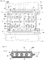
- the electromagnetic shielding device 1 is constituted by a conductive sheet 3 in which a plurality of slits 30 are formed, outer edge portion coupling members 5, and anti-slip members 4.
- the wire harness 100 includes a plurality of electrical wires 9 and the electromagnetic shielding device 1 that surrounds the periphery of the plurality of electrical wires 9 collectively.
- the electrical wires 9 are insulated electrical wires each composed of a core wire that is made of a conductive material and an insulating coating that is made of an insulating material and covers the periphery of the core wire.
- metal terminals which are not shown, are connected to the core wires at end portions of the electrical wires 9.
- the wire harness 100 includes an electrical wire group holding member, which is not shown, the electrical wire group holding member keeping the end portions of the plurality of electrical wires 9 in a fixed positional relationship and being made of a resin material that electrically insulates the plurality of electrical wires 9 from one another.
- the electrical wires 9 are drawn with phantom lines (long dashed double-short dashed lines).
- the conductive sheet 3 that constitutes the electromagnetic shielding device 1 is a sheet-shaped flexible conductive member that can be deformed into a tube shape.
- the conductive sheet 3 is, for example, a metallic cloth or a thin plate material made of a metal.
- the metallic cloth is a metallic thread fabric.
- the metallic cloth is a material having a mesh structure obtained by weaving metallic threads containing, for example, copper as the main component so as to intersect each other vertically and horizontally.
- the metallic cloth has a structure in which a film is affixed to a material made of metallic threads. This film is made of a resin material and is flexible.
- the metallic cloth is conductive and flexible.
- first outer edge portion 31 the second outer edge portion 32
- third outer edge portion 33 the direction from the first outer edge portion 31 toward the second outer edge portion 32
- second direction the direction from the third outer edge portion 33 toward the fourth outer edge portion 34
- the conductive sheet 3 is kept in a tube shape in a state in which the first outer edge portion 31 and the second outer edge portion 32 on the side opposite to the first outer edge portion 31 are joined together.
- the first outer edge portion 31 and the second outer edge portion 32 can also be considered as outer edge portions that constitute the two end portions of the conductive sheet 3 in a direction in which the conductive sheet 3 surrounds the periphery of the electrical wires 9.
- the first direction can also be said to be the direction in which the conductive sheet 3 surrounds the periphery of the electrical wires 9.
- the second direction is the lengthwise direction of the electrical wires 9.
- the third outer edge portion 33 is a portion that occupies a certain range extending inward from an outer edge, of the four outer edges of the conductive sheet 3, that forms one end in the lengthwise direction of the electrical wires 9 and is an attachment target.
- the fourth outer edge portion 34 is a portion that occupies a certain range extending inward from an outer edge of the conductive sheet 3 on the side opposite to the third outer edge portion 33.
- a parallel slit group 300 is formed in the conductive sheet 3, the parallel slit group 300 being constituted by a plurality of slits 30 that extend in a direction that crosses the first direction and that are lined up in the first direction at a distance from one another.
- a plurality of parallel slit groups 300 are formed such that the parallel slit groups 300 are arranged side by side at a distance from one another in the second direction.
- all of the plurality of slits 30 are formed into a straight line shape extending in the second direction. Accordingly, in each of the parallel slit groups 300, the plurality of slits 30 are formed such that the slits 30 are lined up in the direction (first direction) that is perpendicular to the direction (second direction) in which each of the slits 30 extends.
- the plurality of slits 30 are formed such that the positions of the slits 30 of a parallel slit group 300 in the first direction are the same as those of another parallel slit group 300 that is adjacent to the former parallel slit group 300 in the second direction. For this reason, in order to avoid a situation in which adjacent slits 30 in the second direction are connected to each other, the plurality of parallel slit groups 300 are formed so as to be arranged side by side at a distance from one another in the second direction.
- the slits 30 of the conductive sheet 3 are formed by, for example, Thomson die-cutting, punching, or the like.
- the slits 30 are formed by punching, in which the conductive sheet 3 is sandwiched between a protruding die (punch) and a recessed die (die).
- punching in which the conductive sheet 3 is sandwiched between a protruding die (punch) and a recessed die (die).
- burrs protruding in the punching direction that is, toward the recessed die are likely to occur at the edges of the slits 30 in the conductive sheet 3. These burrs may damage the electrical wires 9.
- the conductive sheet 3 is deformed into a tube shape such that the surface of the conductive sheet 3 on the side on which the recessed die was situated during the processing for forming the slits 30 becomes the external surface.
- the outer edge portion coupling members 5 are members that couple the first outer edge portion 31 and the second outer edge portion 32 of the conductive sheet 3 to each other.
- the first outer edge portion 31 and the second outer edge portion 32 of the conductive sheet 3 are coupled to each other by the outer edge portion coupling members 5.
- the conductive sheet 3 is kept in a tube shape in a state in which the first outer edge portion 31 and the second outer edge portion 32 are joined together.
- the outer edge portion coupling members 5 are an example of tube-shape holding members.
- the outer edge portion coupling members 5 shown in FIGS. 1 and 3 are crimp fittings that couple the first outer edge portion 31 and the second outer edge portion 32 of the conductive sheet 3 to each other.
- the first outer edge portion 31 and the second outer edge portion 32 of the conductive sheet 3 are coupled to each other by a plurality of outer edge portion coupling members 5 at a plurality of positions.
- a plurality of through holes 36 into which a plurality of crimp fittings (outer edge portion coupling members 5) are inserted are formed in the first outer edge portion 31 and the second outer edge portion 32 of the conductive sheet 3.
- the electromagnetic shielding device 1 includes two anti-slip members 4.
- the two anti-slip members 4 are metal members that are joined to the third outer edge portion 33 and the fourth outer edge portion 34, respectively, of the conductive sheet 3.
- the anti-slip members 4 are joined to the surface of the conductive sheet 3 that is located on the inner side when the conductive sheet 3 is kept in a tube shape.
- the anti-slip members 4 are joined to the conductive sheet 3 in a state in which electrical continuity is established between the conductive sheet 3 and the anti-slip members 4.
- the anti-slip members 4 are joined to the conductive sheet 3 by welding.
- a plurality of projections 41 are formed on internal surfaces of the anti-slip members 4 on the opposite side of external surfaces of the anti-slip members 4 that are joined to the conductive sheet 3. That is to say, the anti-slip members 4 are metal members that form projections protruding from the surface of the conductive sheet 3.
- the anti-slip members 4 are thin flexible metal plates that can be deformed into a tube shape. Moreover, the plurality of projections 41 are formed by embossing the thin metal plates. Therefore, a plurality of recesses respectively corresponding to the plurality of projections 41 are formed on the external surfaces of the thin plate-shaped anti-slip members 4.
- FIG. 3 is a plan view of the wire harness 100 in a state in which it is attached to the casings 8.
- FIG. 4 is a cross-sectional view of the wire harness 100 in the state in which it is attached to the casings 8. The cross-sectional view in FIG. 4 is a cross-sectional view taken along plane III-III indicated in FIG. 3 .
- the electrical wires 9 and the casings 8 are drawn with phantom lines (long dashed double-short dashed lines).
- the electrical wires 9 of the wire harness 100 are routed from the outside of the metal casings 8 into the casings 8 through openings in the casings 8.
- a metal shield frame portion 81 is formed at an edge of the electrical wire introduction opening in each casing 8, the shield frame portion 81 surrounding the opening.
- one of the third outer edge portion 33 and the fourth outer edge portion of the conductive sheet 3 is fixed to the shield frame portion 81 of the casing 8 with a crimp ring 6, the casing 8 accommodating an apparatus to which one end portion of each of the electrical wires 9 is connected.
- the other one of the third outer edge portion 33 and the fourth outer edge portion of the conductive sheet 3 is fixed to the shield frame portion 81 of the casing 8 with a crimp ring 6, the casing 8 accommodating another apparatus to which the other end portion of each of the electrical wires 9 is connected.
- the third outer edge portion 33 and the fourth outer edge portion 34 of the conductive sheet 3 are respectively placed over the shield frame portions 81 of the two casings 8 with the anti-slip members 4 being located on the inner side.
- the thin plate-shaped anti-slip members 4 are bent along the outer circumferential surfaces of the shield frame portions 81.
- the entire conductive sheet 3 is deformed into a tube shape surrounding the periphery of the portion of the electrical wires 9 that extends between the two casings 8.
- the conductive sheet 3 forms a cylindrical shape.
- the shapes of the third outer edge portion 33 and the fourth outer edge portion 34 of the conductive sheet 3 that is kept in a tube shape vary depending respectively on the shapes of the shield frame portions 81 of the casings 8 to which those outer edge portions are to be fixed.
- the targets over which the third outer edge portion 33 and the fourth outer edge portion 34 of the conductive sheet 3 are to be placed are other supports such as metal pipes for electrical wire protection through which the electrical wires 9 pass, instead of the shield frame portions 81 of the casings 8.
- the first outer edge portion 31 and the second outer edge portion 32 of the conductive sheet 3 are coupled to each other by the outer edge portion coupling members 5.
- one of a pair of metal fittings constituting each of the crimp fittings is inserted into the through holes 36 that are formed in the first outer edge portion 31 and the second outer edge portion 32 of the conductive sheet 3.
- the pair of metal fittings are fastened to each other with a crimping tool in a state in which the first and second overlapping outer edge portions 31 and 32 are clamped therebetween.
- the conductive sheet 3 is kept in a tube shape in a state in which the first outer edge portion 31 and the second outer edge portion are joined together.
- the crimp rings 6 are metal members that each have a ring shape as a result of the two end portions thereof being joined together.
- Each crimp ring 6 is kept in a ring shape by coupling portions 61 that are formed at the two end portions thereof being coupled to each other with a screw 71 and a nut member 72.
- the crimp rings 6 are kept in the ring shapes in a state in which the crimp rings 6 externally squeeze the third outer edge portion 33 and the fourth outer edge portion 34, respectively, of the conductive sheet 3 that are placed over the shield frame portions 81.
- the third outer edge portion 33 and the fourth outer edge portion 34 of the conductive sheet 3 are fixed to the shield frame portions 81 in a state in which these outer edge portions are each clamped between the crimp ring 6 and the shield frame portion 81.
- the anti-slip members 4 are clamped by the third outer edge portion 33 and the fourth outer edge portion 34, respectively, of the conductive sheet 3 and the corresponding shield frame portions 81.
- the plurality of projections 41 of the anti-slip members 4 are strongly pressed against the external surfaces of the shield frame portions 81. That is to say, the force with which each crimp ring 6 squeezes the corresponding shield frame portion 81 is concentrated at the vertex portions of the plurality of projections 41.
- the conductive sheet 3 which is conductive and is joined to the two anti-slip members 4, is also electrically connected to the two casings 8.
- the conductive sheet 3 blocks electromagnetic noise directed toward the electrical wires 9 or generated from the electrical wires 9 by being electrically connected to the casings 8 while surrounding the periphery of the electrical wires 9.
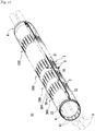
- FIG. 5 is a plan view of a portion of the conductive sheet 3 of the electromagnetic shielding device 1 that is laid along a bent path.
- the conductive sheet 3 kept in a tube shape can be bent at a portion where the parallel slit group 300 is formed, without being largely deformed into a flat shape.
- the electromagnetic shielding device 1 surrounds the periphery of the electrical wires 9 by the flexible conductive sheet 3 being kept in a tube shape in a state in which the first outer edge portion 31 and the second outer edge portion 32 are joined together.
- the electromagnetic shielding device 1 is not a member that is formed into a tube shape in advance, and therefore enables post-provision on the electrical wires 9 and the shield frame portions 81 (supports).
- the electromagnetic shielding device 1 can be mounted on the electrical wires 9 after the connectors or the like are attached to the end portions the electrical wires 9. Furthermore, the electromagnetic shielding device 1 can also be mounted on the electrical wires 9 after the electrical wires 9 are routed from the outside of the casings 8 to the inside.
- the electromagnetic shielding device 1 it is sufficient if a conductive sheet 3 having a size that is neither too large nor too small to surround the periphery of the electrical wires 9 is employed. For this reason, the electromagnetic shielding device 1 can be employed without increasing the layout space, weight, and manufacturing cost.
- the electromagnetic shielding device 1 can even cover the periphery of the electrical wires 9 that extend along a bent path. If this is the case, the electromagnetic shielding device 1 provides a high degree of freedom in laying.
- the conductive sheet 3 of the electromagnetic shielding device 1 can be bent at a portion where a parallel slit group 300 is formed, without being largely deformed into a flat shape. Therefore, at the bent portion of the conductive sheet 3, deformation of the conductive sheet 3 into a flat shape is suppressed. Consequently, even in the case where the electromagnetic shielding device 1 is laid along a bent path, the electrical wires 9 can be electromagnetically shielded without necessitating an increase in the size of the conductive sheet 3.
- the electromagnetic shielding device 1 a plurality of parallel slit groups 300 are formed at a plurality of positions in the conductive sheet 3. Therefore, the conductive sheet 3 kept in a tube shape can be bent at the plurality of positions without being largely deformed into a flat shape. Consequently, the electromagnetic shielding device 1 can also be laid along a path that is bent at a plurality of positions. This increases the degree of freedom in the laying path even more.
- the conductive sheet 3 is kept in a tube shape by the two outer edge portions being coupled to each other.
- the shapes of the openings at the end portions of a tube formed by the conductive sheet 3 can be freely changed because of the flexibility of the conductive sheet 3 and the anti-slip members 4. Therefore, the electromagnetic shielding device 1 has excellent adaptability to the shapes of the supports such as the shield frame portions 81 over which the openings of the tube-shaped conductive sheet 3 are respectively to be placed.
- the surface of a metallic cloth has minute irregularities like the surface of a braided wire, the irregularities being formed by thin metal wires. Therefore, the frictional resistance of the surface of a metallic cloth is extremely small. If the conductive sheet 3 having a small frictional resistance like a metallic cloth is used, when the conductive sheet 3 is clamped and fixed between the shield frame portions 81 of the casings and other fixing members such as crimp fittings, the conductive sheet 3 is likely to slip off the shield frame portions 81.
- the conductive sheet 3 is joined to the anti-slip members 4 in advance by welding or the like. Furthermore, due to the effect of the plurality of projections 41 that are formed on the anti-slip members 4, the frictional resistance between the anti-slip members 4 and the shield frame portions 81 increases. Thus, occurrence of the problem of the electromagnetic shielding device 1 slipping off the shield frame portions 81 of the casings 8 can be suppressed.
- the electromagnetic shielding device 1A differs from the electromagnetic shielding device 1, which is shown in FIGS. 1 to 5 , only in the positional relationship of the slits 30 among the plurality of parallel slit groups 300 of the conductive sheet 3.
- FIG. 6 is a plan view of the electromagnetic shielding device 1A.
- FIG. 7 is a plan view of the wire harness 100A and the casings 8 to which the wire harness 100A is attached.
- the electrical wires 9 and the casings 8 are drawn with phantom lines (long dashed double-short dashed lines).
- constituent elements that are the same as those shown in FIGS. 1 to 5 are denoted by the same reference numerals.
- a plurality of parallel slit groups 300 are formed in the conductive sheet 3 of the electromagnetic shielding device 1A.
- the plurality of slits 30 of the conductive sheet 3 are formed such that the positions of the slits 30 of a parallel slit group 300 in the first direction are offset from those of another parallel slit group 300 that is adjacent to the former parallel slit group 300 in the second direction.
- the first direction refers to the direction from the first outer edge portion 31 toward the second outer edge portion 32 of the conductive sheet 3
- the second direction refers to the direction from the third outer edge portion 33 toward the fourth outer edge portion 34 of the conductive sheet 3.
- the electromagnetic shielding device 1A When the electromagnetic shielding device 1A is employed, effects that are similar to the effects that are achieved when the electromagnetic shielding device 1 is employed can be achieved. Furthermore, in the conductive sheet 3 of the electromagnetic shielding device 1A, it is possible to form the plurality of parallel slit groups 300 in close proximity to one another while preventing the slits 30 of a parallel slit group 300 from being connected to the slits 30 of another parallel slit group 300 that is adjacent to the former parallel slit group 300.
- the conductive sheet 3 kept in a tube shape can be bent at a plurality of portions that are in close proximity to one another, without being largely deformed into a flat shape. Consequently, the electromagnetic shielding device 1A can be laid along a path that is bent in a more complicated manner, and the degree of freedom in the laying path is increased even more.
- FIG. 8 is a perspective view of the electromagnetic shielding device 1B.
- FIG. 9 is a front view of the electromagnetic shielding device 1B.
- FIG. 10 is a plan view of the wire harness 100B.
- FIG. 11 is a plan view of the wire harness 100B in a state in which it is attached to the casings 8.
- FIG. 12 is a cross-sectional view of the wire harness 100B in the state in which it is attached to the casings 8.
- the electrical wires 9 are drawn with phantom lines (long dashed double-short dashed lines).
- the cross-sectional view in FIG. 12 is a cross-sectional view taken along plane II-II in FIG. 11 .
- FIGS. 8 to 12 constituent elements that are the same as those shown in FIGS. 1 to 5 are denoted by the same reference numerals. Hereinafter, only the differences of the electromagnetic shielding device 1B from the electromagnetic shielding device 1 will be described.
- the electromagnetic shielding device 1B is constituted by two bracket members 2 and the conductive sheet 3 that is joined to the two bracket members 2. Also, as shown in FIG. 10 , the wire harness 100B includes the plurality of electrical wires 9 and the electromagnetic shielding device 1B that covers the periphery of the plurality of electrical wires 9 collectively.
- one of the two bracket members 2 is fixed to the shield frame portion 81 of the casing 8 that accommodates an apparatus to which one end portion of each of the electrical wires 9 is connected, and the other one of the two bracket members 2 is fixed to the shield frame portion 81 of the casing 8 that accommodates another apparatus to which the other end portion of each of the electrical wires 9 is connected.
- Each of the two bracket members 2 is fixed to the shield frame portion 81 of the corresponding metal casing 8 by end portions thereof being coupled to each other with a screw 7.
- the electromagnetic shielding device 1B differs from the electromagnetic shielding device 1 shown in FIGS. 1 to 5 in the structure for keeping the conductive sheet 3 in a tube shape and the structure for fixing the third outer edge portion 33 and the fourth outer edge portion 34 of the conductive sheet 3 to the respective supports.
- the electromagnetic shielding device 1B differs from the electromagnetic shielding device 1 shown in FIGS. 1 to 5 in the structure for keeping the conductive sheet 3 in a tube shape and the structure for fixing the third outer edge portion 33 and the fourth outer edge portion 34 of the conductive sheet 3 to the respective supports.
- the bracket members 2 are bent plate-shaped members made of a conductive material.
- the bracket members 2 are made of a metal such as, for example, a copper alloy, iron, aluminum, or stainless steel, and a plating layer may be formed on the surfaces thereof, if necessary.
- the bracket members 2 are fixed to the respective shield frame portions 81 of the metal casings 8, and relay the electrical connection between the conductive sheet 3 and the casings 8.
- each bracket member 2 is composed of two elongated portions 10, a connecting portion 19 that connects one end of each of the two elongated portions 10, and two eave portions 20 that are respectively connected to the other ends of the two elongated portions 10.
- Bracket member elongated portion
- Each of the two elongated portions 10 is a bent plate-shaped portion, and is formed in the shape of a half-ring that spans over the plurality of electrical wires 9 to be magnetically shielded.
- the two elongated portions 10 are combined with each other on two sides of the electrical wires 9, and thus form a ring shape surrounding the periphery of the electrical wires 9.
- each of the elongated portions 10 that extends across the electrical wires 9 is formed into a flat plate-like shape.
- the shapes of the elongated portions 10 may vary depending on the respective shapes of the shield frame portions 81 of the casings 8 to which the elongated portions 10 are to be fixed.
- the two elongated portions 10 are joined to the conductive sheet 3 in a state in which these portions are arranged in series along an outer edge portion of the conductive sheet 3.
- the conductive sheet 3 and the elongated portions 10 are joined by, for example, welding.
- the two elongated portions 10 of one of the two bracket members 2 are joined to the conductive sheet 3 in a state in which they are arranged in series along the third outer edge portion 33 of the conductive sheet 3.
- the two elongated portions 10 of the other one of the two bracket members 2 are joined to the conductive sheet 3 in a state in which they are arranged in series along the fourth outer edge portion 34 of the conductive sheet 3.
- the two elongated portions 10 are formed along a path that is turned back in the connecting portion 19, which will be described later. Therefore, the conductive sheet 3 that is joined to the two elongated portions 10 is kept, by the two elongated portions 10, in a state in which the conductive sheet 3 is turned back in an intermediate portion 35.
- each of the two bracket members 2 external surfaces of the two elongated portions 10 are joined to the conductive sheet 3, the external surfaces being located on the side opposite to the side on which the two elongated portions 10 oppose each other.
- a plurality of projections 11 are formed on internal surfaces of the two elongated portions 10, the internal surfaces being located on the side on which the two elongated portions 10 oppose each other.
- the plurality of projections 11 are formed by embossing. Therefore, a plurality of recesses 11x respectively corresponding to the plurality of projections 11 are formed on the external surfaces of the two elongated portions 10.
- the two bracket members 2 double as the metal anti-slip members, which form the projections protruding from the surfaces of the third outer edge portion 33 and the fourth outer edge portion 34 of the conductive sheet 3.
- Bracket member connecting portion
- the connecting portion 19 is a turn-back plate-shaped portion, and is formed so as to be continuous with one end of each of the two elongated portions 10. That is to say, the two elongated portions 10 and the connecting portion 19 are composed of a single continuous member.
- the connecting portion 19 is flexible in a direction in which the turn-back angle changes. As shown in FIG. 2 , the flexibility of the connecting portion 19 enables the two elongated portions 10 to relatively pivot with the connecting portion 19 serving as the fulcrum. Thus, each bracket member 2 can be deformed to an open state in which the end portions of the respective elongated portions 10 are spaced apart from each other and the interior is freed, and to a closed state in which those end portions are in contact with each other.
- the bracket member 2 in the open state is drawn with solid lines
- the bracket member 2 in the closed state is drawn with phantom lines (long dashed double-short dashed lines).
- the conductive sheet 3 joined to the two bracket members 2 is also put in an open state in which the first outer edge portion 31 and the second outer edge portion 32 are spaced apart from each other.
- the conductive sheet 3 joined to the two bracket members 2 is kept in a tube shape in a state in which the first outer edge portion 31 and the second outer edge portion 32 are joined together.
- the two bracket members 2 are joined to the conductive sheet 3 in a state in which the bracket members 2 extend along the third outer edge portion 33 and the fourth outer edge portion 34, respectively, of the conductive sheet 3, and each of the two bracket members 2 has a ring shape as a result of the end portions thereof being coupled to each other. Then, the two bracket members 2 keep the conductive sheet 3 in a tube shape by keeping the third outer edge portion 33 and the fourth outer edge portion 34, respectively, of the conductive sheet 3 in ring shapes. It should be noted that the two bracket members 2 serve as an example of the tube-shape holding member.
- the first outer edge portion 31 and the second outer edge portion 32 of the conductive sheet 3 are formed so as to extend slightly beyond the respective ends of the two elongated portions 10. Therefore, when the two bracket members 2 are both in the closed state, the first outer edge portion 31 and the second outer edge portion 32 of the conductive sheet 3 are in contact with each other with little or no gap therebetween. The conductive sheet 3 is thus deformed into a tube shape with little or no gap.
- Bracket member eave portion
- the two eave portions 20 are flat plate-shaped portions that are continuous with the other ends of the two elongated portions 10, respectively, and protrude laterally from the two elongated portions 10, respectively.
- each bracket member 2 is a single continuous metal member in which the two elongated portions 10, the connecting portion 19, and the two eave portions 20 that are respectively continuous with the other ends of the two elongated portions 10 are formed. That is to say, the two elongated portions 10 are composed of a single continuous metal member together with the connecting portion 19, which connects the ends of the two elongated portions 10 to each other and is flexible, and the two eave portions 20, which are respectively continuous with the other ends of the two elongated portions 10.
- the two eave portions 20 overlap each other. Also, a screw hole 21 in which the screw 7 is inserted is formed in each of the two eave portions 20.
- the screw holes 21 are through holes that communicate with each other in a state in which the two eave portions 20 overlap each other.
- Each bracket member 2 has a ring shape as a result of the two eave portions 20 overlapping each other.
- the two overlapping eave portions 20 are kept in a combined state by the screw 7 being inserted therein.
- the end portions of the two elongated portions 10 are coupled to each other, so that the two elongated portions 10 are kept in a ring shape.
- a screw thread that engages with the screw 7 is formed in an inner edge portion of the screw hole 21 in each of the two eave portions 20. With this configuration, the screw 7 can be directly fastened to the eave portions 20, and the need for the nut member for combining the two eave portions 20 together is eliminated.
- a fixing device for keeping the two elongated portions 10 in a ring shape may also be composed of the two eave portions 20 in which the through holes are formed, the screw 7, and the nut member to which the screw 7 is fastened.
- the nut member is secured by welding or the like to one of the two overlapping eave portions 20 in advance.
- each of the two bracket members 2 includes the two elongated portions 10, the connecting portion 19 that connects one end of each of the two elongated portions 10, and the eave portions 20 located at respective end portions of the two elongated portions 10 and coupled to each other.
- the two bracket members 2 keep the third outer edge portion 33 and the fourth outer edge portion 34, respectively, of the four outer edge portions of the conductive sheet 3 in ring shapes surrounding the periphery of the electrical wires 9, the fourth outer edge portion 34 being located on the side opposite to the third outer edge portion 33.
- one of the two bracket members 2 is fixed to the shield frame portion 81 of the casing 8 that accommodates an apparatus to which one end portion of each of the electrical wires 9 is connected, and the other one of the two bracket members 2 is fixed to the shield frame portion 81 of the casing 8 that accommodates another apparatus to which the other end portion of each of the electrical wires 9 is connected.
- the two bracket members 2 both in the open state are placed over the respective shield frame portions 81 of the two casings 8, and the conductive sheet 3 that is also in the open state (non-tube-shaped body) is placed over the portion of the electrical wires 9 that extends between the two casings 8.
- the two bracket members 2 are both put in the closed state on the outer side of the respective shield frame portions 81.
- the two elongated portions 10 of each of the two bracket members 2 clamp the shield frame portion 81 therebetween, and the conductive sheet 3 is deformed into a tube shape surrounding the periphery of the electrical wires 9.
- the plurality of projections 11 of the two elongated portions 10 are strongly pressed against the external surface of the shield frame portion 81. That is to say, the force with which the two elongated portions 10 clamp the shield frame portion 81 therebetween is concentrated at the vertex portions of the plurality of projections 11.
- each of the two screws 7 is inserted into the screw holes 21 in the two overlapping eave portions 20 of each of the two bracket members 2, so that the two eave portions 20 are kept in an overlapping state by the screw 7.
- the two bracket members 2 are both kept in the closed state and fixed to the respective shield frame portions 81.
- the two bracket members 2 are fixed to the respective shield frame portions 81 of the two casings 8, the two bracket members 2 are electrically connected to the two casings 8, respectively. Therefore, the conductive sheet 3, which is conductive and is joined to the two bracket members 2, is also electrically connected to the two casings 8.
- the conductive sheet 3 Since the conductive sheet 3 is electrically connected to the casings 8 in a state in which it surrounds the periphery of the electrical wires 9, the conductive sheet 3 blocks electromagnetic noise directed toward the electrical wires 9 or generated from the electrical wires 9.
- the two bracket members 2 are shaped into shapes that match the respective shapes of the supports such as the shield frame portions 81 of the casings 8 in advance.
- the two bracket members 2 have the function of keeping the conductive sheet 3 in a tube shape and also the function of maintaining the electrical connection between the conductive sheet 3 and the shield frame portions 81 of the casings 8. Accordingly, when the electromagnetic shielding device 1B is employed, the number of man-hours required for management and handling of components is reduced as compared with the case where handling of a plurality of members is performed by using a crimp fitting.
- the conductive sheet 3 is joined to the elongated portions 10 of the two bracket members 2 in advance. Therefore, the two bracket members 2 can be directly fixed to the shield frame portions 81 without interposing the conductive sheet 3 therebetween. Accordingly, the problem of the electromagnetic shielding device 1B detaching from the shield frame portions 81 of the casings 8 is unlikely to occur.
- the frictional resistance between the elongated portions 10 and the shield frame portions 81 is increased. Accordingly, the force with which the bracket members 2 are kept on the respective shield frame portions 81 increases. Consequently, occurrence of the problem of the electromagnetic shielding device 1B detaching from the shield frame portions 81 of the casings 8 can be suppressed even more.
- the two elongated portions 10 of each of the two bracket members 2 are composed of a single continuous member together with the connecting portion 19. Therefore, when the electromagnetic shielding device 1B is employed, the number of components is reduced as compared with the case where the two elongated portions 10 are separate members. Therefore, the number of man-hours required for attachment to the casings 8 can be reduced.
- the conductive sheet 3 is joined to the external surfaces of the elongated portions 10. Therefore, the conductive sheet 3 is not sandwiched between the elongated portions 10 and the shield frame portions 81 of the casings 8. Therefore, it is unnecessary to separately form portions of the elongated portions 10 that come into contact with the shield frame portions 81 and portions of the elongated portions 10 that are joined to the conductive sheet 3 in order to prevent the conductive sheet 3 from being sandwiched. Accordingly, the size of the elongated portions 10 (bracket members 2) can be reduced.
- an electromagnetic shielding device 1C according to a fourth embodiment of the present invention will be described with reference to FIG. 13 .
- This electromagnetic shielding device 1C differs from the electromagnetic shielding device 1 shown in FIGS. 1 to 5 in that a folding line 301 that extends across each parallel slit group 300 is formed on the conductive sheet 3 in advance.
- constituent elements that are the same as those shown in FIGS. 1 to 5 are denoted by the same reference numerals.
- only the differences of the electromagnetic shielding device 1C from the electromagnetic shielding device 1 will be described.
- the folding lines 301 on the conductive sheet 3 constitute ridges that are formed as a result of the portions between the plurality of slits 30 of the individual parallel slit groups 300 rising from the external surface of the tube-shaped conductive sheet 3 and being bent. Furthermore, the folding lines 301 are formed so as to extend across the respective parallel slit groups 300. In this embodiment, the folding lines 301 on the conductive sheet 3 are formed so as to extend across the respective parallel slit groups 300 in the first direction.
- the portions between the plurality of slits 30 in the inner portion of the bent portion of the conductive sheet 3 are bent so as to protrude outward from the outer circumferential surface.
- the folding lines 301 on the conductive sheet 3 are formed in order to make the portions between the plurality of slits 30 be easily bent so as to protrude outward from the outer circumferential surface.
- the employment of the electromagnetic shielding device 1C shown in FIG. 13 further facilitates the deformation of the conductive sheet 3 along a bent path.
- all of the plurality of slits 30 of the conductive sheet 3 are formed into a straight line shape extending in the second direction.
- the plurality of slits 30 are formed so as to extend in a direction that is inclined with respect to the second direction.
- the parallel slit group 300 in the conductive sheet 3 is formed at only one position in the conductive sheet 3 in the second direction. Also, in the electromagnetic shielding devices 1, 1A, and 1B, the parallel slit groups 300 are formed in a range over almost the entire conductive sheet 3 in the first direction.
- the parallel slit groups 300 are formed in only a range that occupies a portion of the conductive sheet 3 in the first direction. In this case, it is sufficient if the parallel slit groups 300 are formed in the inner portion of the bent portion of the tube-shaped conductive sheet 3.
- the anti-slip members 4 may also be composed of a plurality of granular metal members that are joined to the surfaces of the third outer edge portion 33 and the fourth outer edge portion 34 of the conductive sheet 3 by welding or the like. Such granular metal members also form the projections protruding from the surfaces of the third outer edge portion 33 and the fourth outer edge portion 34 of the conductive sheet 3.
- each of the two bracket members 2 is composed of two metal members that form a ring shape as a result of being combined with each other.
- each bracket member 2 is composed of two half-ring-shaped metal members.
- each half-ring-shaped metal member is composed of a single elongated portion 10 and two eave portions 20 respectively formed at the two ends of the elongated portion 10.
- the electromagnetic shielding devices 1, 1A, 1B, and 1C it is also conceivable that a conductive sheet 3 in which not slits 30 are formed is employed.
- the conductive sheet 3 is flexible as well, and therefore the electromagnetic shielding device 1 can surround the periphery of the electrical wires 9 that extend along a bent path.
Landscapes
- Engineering & Computer Science (AREA)
- Architecture (AREA)
- Civil Engineering (AREA)
- Structural Engineering (AREA)
- Microelectronics & Electronic Packaging (AREA)
- Mechanical Engineering (AREA)
- Physics & Mathematics (AREA)
- Electromagnetism (AREA)
- Shielding Devices Or Components To Electric Or Magnetic Fields (AREA)
- Insulated Conductors (AREA)
- Details Of Indoor Wiring (AREA)
Applications Claiming Priority (2)
| Application Number | Priority Date | Filing Date | Title |
|---|---|---|---|
| JP2012010866A JP5880070B2 (ja) | 2012-01-23 | 2012-01-23 | 電磁シールド具及びワイヤハーネス |
| PCT/JP2012/082923 WO2013111480A1 (ja) | 2012-01-23 | 2012-12-19 | 電磁シールド具及びワイヤハーネス |
Publications (3)
| Publication Number | Publication Date |
|---|---|
| EP2797397A1 EP2797397A1 (en) | 2014-10-29 |
| EP2797397A4 EP2797397A4 (en) | 2015-11-11 |
| EP2797397B1 true EP2797397B1 (en) | 2018-11-28 |
Family
ID=48873219
Family Applications (1)
| Application Number | Title | Priority Date | Filing Date |
|---|---|---|---|
| EP12866922.3A Not-in-force EP2797397B1 (en) | 2012-01-23 | 2012-12-19 | Electromagnetic shielding device and wire harness |
Country Status (6)
| Country | Link |
|---|---|
| US (1) | US9089048B2 (ko) |
| EP (1) | EP2797397B1 (ko) |
| JP (1) | JP5880070B2 (ko) |
| KR (1) | KR101609966B1 (ko) |
| CN (1) | CN104067700A (ko) |
| WO (1) | WO2013111480A1 (ko) |
Families Citing this family (31)
| Publication number | Priority date | Publication date | Assignee | Title |
|---|---|---|---|---|
| JP5942703B2 (ja) | 2012-01-23 | 2016-06-29 | 株式会社オートネットワーク技術研究所 | 電磁シールド具及びワイヤハーネス |
| JP6163699B2 (ja) * | 2013-07-08 | 2017-07-19 | 矢崎総業株式会社 | ワイヤハーネス |
| US9769943B2 (en) | 2013-08-09 | 2017-09-19 | Peter Chin | Cable management device |
| JP6086323B2 (ja) * | 2013-10-04 | 2017-03-01 | 住友電装株式会社 | シールドパイプ |
| JP2015162474A (ja) * | 2014-02-26 | 2015-09-07 | 株式会社オートネットワーク技術研究所 | 電磁シールド部材 |
| JP6229540B2 (ja) * | 2014-02-27 | 2017-11-15 | 株式会社オートネットワーク技術研究所 | 電磁シールド部材 |
| JP2015173191A (ja) * | 2014-03-12 | 2015-10-01 | 株式会社オートネットワーク技術研究所 | 電磁シールド部材 |
| JP2015201467A (ja) * | 2014-04-04 | 2015-11-12 | 株式会社オートネットワーク技術研究所 | 電磁シールド部材及び電磁シールド部材製造方法 |
| JP2015201986A (ja) * | 2014-04-09 | 2015-11-12 | 株式会社オートネットワーク技術研究所 | 電磁シールド部材 |
| USD762588S1 (en) * | 2014-04-10 | 2016-08-02 | Peter Chin | Cable management device |
| JP6326271B2 (ja) * | 2014-04-21 | 2018-05-16 | 矢崎総業株式会社 | 電線のシールド構造 |
| US20150330478A1 (en) * | 2014-05-14 | 2015-11-19 | Beats Electronics, Llc | Cable management member |
| USD775937S1 (en) * | 2014-12-21 | 2017-01-10 | Michael Davis | Device for securing a cable |
| WO2016158732A1 (ja) * | 2015-03-27 | 2016-10-06 | 古河電気工業株式会社 | 電磁シールド管、電磁シールド構造 |
| JP6204412B2 (ja) * | 2015-06-12 | 2017-09-27 | 矢崎総業株式会社 | ワイヤーハーネス |
| CN105072880B (zh) * | 2015-08-05 | 2018-03-13 | 华东师范大学 | 一种基于双层截止圆波导阵列金属网/膜的电磁屏蔽结构 |
| USD799941S1 (en) * | 2015-08-21 | 2017-10-17 | Elasco Products, LLC | Cable protector |
| USD808250S1 (en) * | 2016-11-07 | 2018-01-23 | Nan Juen International Co., Ltd. | Wire management device |
| JP6816660B2 (ja) * | 2017-06-15 | 2021-01-20 | 株式会社オートネットワーク技術研究所 | 電磁シールド部品、ワイヤハーネス及び電磁シールド部品の製造方法 |
| TWI668708B (zh) * | 2017-07-07 | 2019-08-11 | 加川清二 | 電磁波吸收纜線 |
| JP6855966B2 (ja) * | 2017-07-19 | 2021-04-07 | 住友電装株式会社 | ワイヤハーネス |
| USD871894S1 (en) * | 2018-09-11 | 2020-01-07 | HIP Product Factory LTD | Cord management device |
| US10720765B2 (en) * | 2018-09-17 | 2020-07-21 | Rockwell Automation Technologies, Inc. | System for isolating power conductors using slidable insulating sheets |
| USD909187S1 (en) | 2019-05-09 | 2021-02-02 | Apple Inc. | Accessory for a cable |
| WO2020261916A1 (ja) * | 2019-06-27 | 2020-12-30 | 株式会社巴川製紙所 | フレキシブル電線 |
| DE102019131499A1 (de) | 2019-11-21 | 2021-05-27 | Carl Freudenberg Kg | Flexibles Laminat zur Abschirmung elektromagnetischer Strahlung |
| JP7314793B2 (ja) * | 2019-12-20 | 2023-07-26 | 株式会社オートネットワーク技術研究所 | 配線部材 |
| USD966079S1 (en) * | 2020-02-18 | 2022-10-11 | Lesley Murray | Cord organizer |
| USD968935S1 (en) * | 2020-04-24 | 2022-11-08 | Flashbay Electronics Hong Kong Limited | Cable holder |
| USD954535S1 (en) * | 2020-04-27 | 2022-06-14 | Flashbay Electronics Hong Kong Limited | Cable holder |
| CN111508644A (zh) * | 2020-04-28 | 2020-08-07 | 安徽省康利亚股份有限公司 | 一种牵引逆变器抗干扰电缆 |
Family Cites Families (12)
| Publication number | Priority date | Publication date | Assignee | Title |
|---|---|---|---|---|
| US5357049A (en) * | 1993-05-19 | 1994-10-18 | The Zippertubing Co. | Closable electrical shielding jacket |
| JPH10173385A (ja) * | 1996-12-09 | 1998-06-26 | Kitagawa Ind Co Ltd | 電線等の電磁シールド部材及び電磁シールド方法 |
| US5967194A (en) | 1998-01-23 | 1999-10-19 | Federal-Mogul Systems Protection Group, Inc. | Self-sealing tubing |
| AU2001259034A1 (en) * | 2000-04-17 | 2001-10-30 | Shielding For Electronics, Inc. | Electromagnetic interference shielding of electrical cables and connectors |
| JP4764556B2 (ja) * | 2001-03-06 | 2011-09-07 | 矢崎総業株式会社 | 導体付き導体薄膜シート |
| JP4579059B2 (ja) | 2005-06-07 | 2010-11-10 | トヨタ自動車株式会社 | シールドシェル |
| FR2916081B1 (fr) * | 2007-05-07 | 2009-09-25 | Fed Mogul Systems Prot Group S | Gaine de protection electromagnetique en textile. |
| JP2009059505A (ja) * | 2007-08-30 | 2009-03-19 | Auto Network Gijutsu Kenkyusho:Kk | シールド導電体 |
| JP5362206B2 (ja) | 2007-12-04 | 2013-12-11 | 矢崎総業株式会社 | シールド部材 |
| JP2010045948A (ja) * | 2008-08-18 | 2010-02-25 | Honda Motor Co Ltd | ハーネスの形状保持方法 |
| JP5419434B2 (ja) * | 2008-12-15 | 2014-02-19 | 矢崎総業株式会社 | シールド電線およびシールド電線の端末シールド構造 |
| US9362725B2 (en) * | 2011-10-28 | 2016-06-07 | Milliken & Company | Electromagnetic shielded sleeve |
-
2012
- 2012-01-23 JP JP2012010866A patent/JP5880070B2/ja not_active Expired - Fee Related
- 2012-12-19 EP EP12866922.3A patent/EP2797397B1/en not_active Not-in-force
- 2012-12-19 US US14/374,020 patent/US9089048B2/en not_active Expired - Fee Related
- 2012-12-19 WO PCT/JP2012/082923 patent/WO2013111480A1/ja active Application Filing
- 2012-12-19 KR KR1020147020399A patent/KR101609966B1/ko active IP Right Grant
- 2012-12-19 CN CN201280067744.4A patent/CN104067700A/zh active Pending
Non-Patent Citations (1)
| Title |
|---|
| None * |
Also Published As
| Publication number | Publication date |
|---|---|
| US9089048B2 (en) | 2015-07-21 |
| CN104067700A (zh) | 2014-09-24 |
| JP2013149895A (ja) | 2013-08-01 |
| KR101609966B1 (ko) | 2016-04-06 |
| EP2797397A4 (en) | 2015-11-11 |
| KR20140105595A (ko) | 2014-09-01 |
| JP5880070B2 (ja) | 2016-03-08 |
| EP2797397A1 (en) | 2014-10-29 |
| WO2013111480A1 (ja) | 2013-08-01 |
| US20140360771A1 (en) | 2014-12-11 |
Similar Documents
| Publication | Publication Date | Title |
|---|---|---|
| EP2797397B1 (en) | Electromagnetic shielding device and wire harness | |
| EP2797189B1 (en) | Electromagnetic shielding tool and wire harness | |
| EP3057105B1 (en) | Wire harness | |
| EP2298608B1 (en) | Device comprising a vehicle and a wire harness | |
| US10236634B2 (en) | Electromagnetic shield member and electromagnetic shield member-equipped wiring device | |
| US9680290B2 (en) | Electric cable with protection member | |
| JP5772640B2 (ja) | 電磁シールド具及びワイヤハーネス | |
| EP2295295B1 (en) | Wire Harness and Method of Installation Thereof | |
| JP5655630B2 (ja) | シールド導電体 | |
| JP6281448B2 (ja) | 導電路 | |
| US10407000B2 (en) | Structure for protecting an electric wire connection and a wire harness | |
| CN105981227B (zh) | 端子台 | |
| JP2016054030A (ja) | ワイヤハーネスおよびシールド導電路 | |
| EP2683044A1 (en) | Protective implement, method of manufacturing same, and shielded conductor | |
| JP2014050263A (ja) | ワイヤハーネス同士の合体構造 | |
| JP2013214690A (ja) | 電磁シールド具及びワイヤハーネス | |
| CN103026570A (zh) | 端子对 | |
| JP6180141B2 (ja) | 電線のシールド構造 | |
| WO2019188100A1 (ja) | ワイヤハーネス | |
| JP7024596B2 (ja) | ワイヤハーネス | |
| JP2012064331A (ja) | ワイヤーハーネス | |
| JP5086046B2 (ja) | シールド部材 | |
| JP2013251426A (ja) | 電磁シールド部材及びワイヤハーネス | |
| WO2014041918A1 (ja) | 電磁シールド具及びワイヤハーネス |
Legal Events
| Date | Code | Title | Description |
|---|---|---|---|
| PUAI | Public reference made under article 153(3) epc to a published international application that has entered the european phase |
Free format text: ORIGINAL CODE: 0009012 |
|
| 17P | Request for examination filed |
Effective date: 20140723 |
|
| AK | Designated contracting states |
Kind code of ref document: A1 Designated state(s): AL AT BE BG CH CY CZ DE DK EE ES FI FR GB GR HR HU IE IS IT LI LT LU LV MC MK MT NL NO PL PT RO RS SE SI SK SM TR |
|
| DAX | Request for extension of the european patent (deleted) | ||
| RA4 | Supplementary search report drawn up and despatched (corrected) |
Effective date: 20151012 |
|
| RIC1 | Information provided on ipc code assigned before grant |
Ipc: H05K 9/00 20060101AFI20151006BHEP Ipc: H02G 3/04 20060101ALI20151006BHEP Ipc: B60R 16/02 20060101ALI20151006BHEP |
|
| GRAP | Despatch of communication of intention to grant a patent |
Free format text: ORIGINAL CODE: EPIDOSNIGR1 |
|
| STAA | Information on the status of an ep patent application or granted ep patent |
Free format text: STATUS: GRANT OF PATENT IS INTENDED |
|
| RIC1 | Information provided on ipc code assigned before grant |
Ipc: B60R 16/02 20060101ALI20180619BHEP Ipc: H02G 3/04 20060101ALI20180619BHEP Ipc: H05K 9/00 20060101AFI20180619BHEP Ipc: H02G 3/06 20060101ALI20180619BHEP |
|
| INTG | Intention to grant announced |
Effective date: 20180719 |
|
| GRAS | Grant fee paid |
Free format text: ORIGINAL CODE: EPIDOSNIGR3 |
|
| GRAA | (expected) grant |
Free format text: ORIGINAL CODE: 0009210 |
|
| STAA | Information on the status of an ep patent application or granted ep patent |
Free format text: STATUS: THE PATENT HAS BEEN GRANTED |
|
| AK | Designated contracting states |
Kind code of ref document: B1 Designated state(s): AL AT BE BG CH CY CZ DE DK EE ES FI FR GB GR HR HU IE IS IT LI LT LU LV MC MK MT NL NO PL PT RO RS SE SI SK SM TR |
|
| REG | Reference to a national code |
Ref country code: GB Ref legal event code: FG4D |
|
| REG | Reference to a national code |
Ref country code: CH Ref legal event code: EP |
|
| REG | Reference to a national code |
Ref country code: AT Ref legal event code: REF Ref document number: 1071849 Country of ref document: AT Kind code of ref document: T Effective date: 20181215 |
|
| REG | Reference to a national code |
Ref country code: DE Ref legal event code: R096 Ref document number: 602012054201 Country of ref document: DE |
|
| REG | Reference to a national code |
Ref country code: IE Ref legal event code: FG4D |
|
| REG | Reference to a national code |
Ref country code: NL Ref legal event code: MP Effective date: 20181128 |
|
| REG | Reference to a national code |
Ref country code: LT Ref legal event code: MG4D |
|
| REG | Reference to a national code |
Ref country code: AT Ref legal event code: MK05 Ref document number: 1071849 Country of ref document: AT Kind code of ref document: T Effective date: 20181128 |
|
| PG25 | Lapsed in a contracting state [announced via postgrant information from national office to epo] |
Ref country code: LV Free format text: LAPSE BECAUSE OF FAILURE TO SUBMIT A TRANSLATION OF THE DESCRIPTION OR TO PAY THE FEE WITHIN THE PRESCRIBED TIME-LIMIT Effective date: 20181128 Ref country code: AT Free format text: LAPSE BECAUSE OF FAILURE TO SUBMIT A TRANSLATION OF THE DESCRIPTION OR TO PAY THE FEE WITHIN THE PRESCRIBED TIME-LIMIT Effective date: 20181128 Ref country code: FI Free format text: LAPSE BECAUSE OF FAILURE TO SUBMIT A TRANSLATION OF THE DESCRIPTION OR TO PAY THE FEE WITHIN THE PRESCRIBED TIME-LIMIT Effective date: 20181128 Ref country code: NO Free format text: LAPSE BECAUSE OF FAILURE TO SUBMIT A TRANSLATION OF THE DESCRIPTION OR TO PAY THE FEE WITHIN THE PRESCRIBED TIME-LIMIT Effective date: 20190228 Ref country code: BG Free format text: LAPSE BECAUSE OF FAILURE TO SUBMIT A TRANSLATION OF THE DESCRIPTION OR TO PAY THE FEE WITHIN THE PRESCRIBED TIME-LIMIT Effective date: 20190228 Ref country code: IS Free format text: LAPSE BECAUSE OF FAILURE TO SUBMIT A TRANSLATION OF THE DESCRIPTION OR TO PAY THE FEE WITHIN THE PRESCRIBED TIME-LIMIT Effective date: 20190328 Ref country code: HR Free format text: LAPSE BECAUSE OF FAILURE TO SUBMIT A TRANSLATION OF THE DESCRIPTION OR TO PAY THE FEE WITHIN THE PRESCRIBED TIME-LIMIT Effective date: 20181128 Ref country code: ES Free format text: LAPSE BECAUSE OF FAILURE TO SUBMIT A TRANSLATION OF THE DESCRIPTION OR TO PAY THE FEE WITHIN THE PRESCRIBED TIME-LIMIT Effective date: 20181128 Ref country code: LT Free format text: LAPSE BECAUSE OF FAILURE TO SUBMIT A TRANSLATION OF THE DESCRIPTION OR TO PAY THE FEE WITHIN THE PRESCRIBED TIME-LIMIT Effective date: 20181128 |
|
| PG25 | Lapsed in a contracting state [announced via postgrant information from national office to epo] |
Ref country code: SE Free format text: LAPSE BECAUSE OF FAILURE TO SUBMIT A TRANSLATION OF THE DESCRIPTION OR TO PAY THE FEE WITHIN THE PRESCRIBED TIME-LIMIT Effective date: 20181128 Ref country code: PT Free format text: LAPSE BECAUSE OF FAILURE TO SUBMIT A TRANSLATION OF THE DESCRIPTION OR TO PAY THE FEE WITHIN THE PRESCRIBED TIME-LIMIT Effective date: 20190328 Ref country code: GR Free format text: LAPSE BECAUSE OF FAILURE TO SUBMIT A TRANSLATION OF THE DESCRIPTION OR TO PAY THE FEE WITHIN THE PRESCRIBED TIME-LIMIT Effective date: 20190301 Ref country code: AL Free format text: LAPSE BECAUSE OF FAILURE TO SUBMIT A TRANSLATION OF THE DESCRIPTION OR TO PAY THE FEE WITHIN THE PRESCRIBED TIME-LIMIT Effective date: 20181128 Ref country code: RS Free format text: LAPSE BECAUSE OF FAILURE TO SUBMIT A TRANSLATION OF THE DESCRIPTION OR TO PAY THE FEE WITHIN THE PRESCRIBED TIME-LIMIT Effective date: 20181128 |
|
| PG25 | Lapsed in a contracting state [announced via postgrant information from national office to epo] |
Ref country code: NL Free format text: LAPSE BECAUSE OF FAILURE TO SUBMIT A TRANSLATION OF THE DESCRIPTION OR TO PAY THE FEE WITHIN THE PRESCRIBED TIME-LIMIT Effective date: 20181128 |
|
| PG25 | Lapsed in a contracting state [announced via postgrant information from national office to epo] |
Ref country code: CZ Free format text: LAPSE BECAUSE OF FAILURE TO SUBMIT A TRANSLATION OF THE DESCRIPTION OR TO PAY THE FEE WITHIN THE PRESCRIBED TIME-LIMIT Effective date: 20181128 Ref country code: PL Free format text: LAPSE BECAUSE OF FAILURE TO SUBMIT A TRANSLATION OF THE DESCRIPTION OR TO PAY THE FEE WITHIN THE PRESCRIBED TIME-LIMIT Effective date: 20181128 Ref country code: DK Free format text: LAPSE BECAUSE OF FAILURE TO SUBMIT A TRANSLATION OF THE DESCRIPTION OR TO PAY THE FEE WITHIN THE PRESCRIBED TIME-LIMIT Effective date: 20181128 Ref country code: IT Free format text: LAPSE BECAUSE OF FAILURE TO SUBMIT A TRANSLATION OF THE DESCRIPTION OR TO PAY THE FEE WITHIN THE PRESCRIBED TIME-LIMIT Effective date: 20181128 |
|
| REG | Reference to a national code |
Ref country code: CH Ref legal event code: PL |
|
| REG | Reference to a national code |
Ref country code: DE Ref legal event code: R097 Ref document number: 602012054201 Country of ref document: DE |
|
| PG25 | Lapsed in a contracting state [announced via postgrant information from national office to epo] |
Ref country code: RO Free format text: LAPSE BECAUSE OF FAILURE TO SUBMIT A TRANSLATION OF THE DESCRIPTION OR TO PAY THE FEE WITHIN THE PRESCRIBED TIME-LIMIT Effective date: 20181128 Ref country code: SK Free format text: LAPSE BECAUSE OF FAILURE TO SUBMIT A TRANSLATION OF THE DESCRIPTION OR TO PAY THE FEE WITHIN THE PRESCRIBED TIME-LIMIT Effective date: 20181128 Ref country code: EE Free format text: LAPSE BECAUSE OF FAILURE TO SUBMIT A TRANSLATION OF THE DESCRIPTION OR TO PAY THE FEE WITHIN THE PRESCRIBED TIME-LIMIT Effective date: 20181128 Ref country code: SM Free format text: LAPSE BECAUSE OF FAILURE TO SUBMIT A TRANSLATION OF THE DESCRIPTION OR TO PAY THE FEE WITHIN THE PRESCRIBED TIME-LIMIT Effective date: 20181128 Ref country code: LU Free format text: LAPSE BECAUSE OF NON-PAYMENT OF DUE FEES Effective date: 20181219 Ref country code: MC Free format text: LAPSE BECAUSE OF FAILURE TO SUBMIT A TRANSLATION OF THE DESCRIPTION OR TO PAY THE FEE WITHIN THE PRESCRIBED TIME-LIMIT Effective date: 20181128 |
|
| REG | Reference to a national code |
Ref country code: IE Ref legal event code: MM4A |
|
| REG | Reference to a national code |
Ref country code: BE Ref legal event code: MM Effective date: 20181231 |
|
| PLBE | No opposition filed within time limit |
Free format text: ORIGINAL CODE: 0009261 |
|
| STAA | Information on the status of an ep patent application or granted ep patent |
Free format text: STATUS: NO OPPOSITION FILED WITHIN TIME LIMIT |
|
| GBPC | Gb: european patent ceased through non-payment of renewal fee |
Effective date: 20190228 |
|
| PG25 | Lapsed in a contracting state [announced via postgrant information from national office to epo] |
Ref country code: SI Free format text: LAPSE BECAUSE OF FAILURE TO SUBMIT A TRANSLATION OF THE DESCRIPTION OR TO PAY THE FEE WITHIN THE PRESCRIBED TIME-LIMIT Effective date: 20181128 Ref country code: IE Free format text: LAPSE BECAUSE OF NON-PAYMENT OF DUE FEES Effective date: 20181219 Ref country code: FR Free format text: LAPSE BECAUSE OF NON-PAYMENT OF DUE FEES Effective date: 20190128 |
|
| 26N | No opposition filed |
Effective date: 20190829 |
|
| PG25 | Lapsed in a contracting state [announced via postgrant information from national office to epo] |
Ref country code: BE Free format text: LAPSE BECAUSE OF NON-PAYMENT OF DUE FEES Effective date: 20181231 |
|
| PG25 | Lapsed in a contracting state [announced via postgrant information from national office to epo] |
Ref country code: CH Free format text: LAPSE BECAUSE OF NON-PAYMENT OF DUE FEES Effective date: 20181231 Ref country code: LI Free format text: LAPSE BECAUSE OF NON-PAYMENT OF DUE FEES Effective date: 20181231 |
|
| PG25 | Lapsed in a contracting state [announced via postgrant information from national office to epo] |
Ref country code: MT Free format text: LAPSE BECAUSE OF NON-PAYMENT OF DUE FEES Effective date: 20181219 Ref country code: GB Free format text: LAPSE BECAUSE OF NON-PAYMENT OF DUE FEES Effective date: 20190228 |
|
| PGFP | Annual fee paid to national office [announced via postgrant information from national office to epo] |
Ref country code: DE Payment date: 20191203 Year of fee payment: 8 |
|
| PG25 | Lapsed in a contracting state [announced via postgrant information from national office to epo] |
Ref country code: TR Free format text: LAPSE BECAUSE OF FAILURE TO SUBMIT A TRANSLATION OF THE DESCRIPTION OR TO PAY THE FEE WITHIN THE PRESCRIBED TIME-LIMIT Effective date: 20181128 |
|
| PG25 | Lapsed in a contracting state [announced via postgrant information from national office to epo] |
Ref country code: MK Free format text: LAPSE BECAUSE OF NON-PAYMENT OF DUE FEES Effective date: 20181128 Ref country code: HU Free format text: LAPSE BECAUSE OF FAILURE TO SUBMIT A TRANSLATION OF THE DESCRIPTION OR TO PAY THE FEE WITHIN THE PRESCRIBED TIME-LIMIT; INVALID AB INITIO Effective date: 20121219 Ref country code: CY Free format text: LAPSE BECAUSE OF FAILURE TO SUBMIT A TRANSLATION OF THE DESCRIPTION OR TO PAY THE FEE WITHIN THE PRESCRIBED TIME-LIMIT Effective date: 20181128 |
|
| REG | Reference to a national code |
Ref country code: DE Ref legal event code: R119 Ref document number: 602012054201 Country of ref document: DE |
|
| PG25 | Lapsed in a contracting state [announced via postgrant information from national office to epo] |
Ref country code: DE Free format text: LAPSE BECAUSE OF NON-PAYMENT OF DUE FEES Effective date: 20210701 |