EP2789736B1 - Entwässerungssystem für eine Schiene - Google Patents
Entwässerungssystem für eine Schiene Download PDFInfo
- Publication number
- EP2789736B1 EP2789736B1 EP14163864.3A EP14163864A EP2789736B1 EP 2789736 B1 EP2789736 B1 EP 2789736B1 EP 14163864 A EP14163864 A EP 14163864A EP 2789736 B1 EP2789736 B1 EP 2789736B1
- Authority
- EP
- European Patent Office
- Prior art keywords
- connecting element
- drainage
- rail
- drainage channels
- channels
- Prior art date
- Legal status (The legal status is an assumption and is not a legal conclusion. Google has not performed a legal analysis and makes no representation as to the accuracy of the status listed.)
- Active
Links
Images





Classifications
-
- E—FIXED CONSTRUCTIONS
- E01—CONSTRUCTION OF ROADS, RAILWAYS, OR BRIDGES
- E01B—PERMANENT WAY; PERMANENT-WAY TOOLS; MACHINES FOR MAKING RAILWAYS OF ALL KINDS
- E01B1/00—Ballastway; Other means for supporting the sleepers or the track; Drainage of the ballastway
- E01B1/008—Drainage of track
-
- E—FIXED CONSTRUCTIONS
- E01—CONSTRUCTION OF ROADS, RAILWAYS, OR BRIDGES
- E01B—PERMANENT WAY; PERMANENT-WAY TOOLS; MACHINES FOR MAKING RAILWAYS OF ALL KINDS
- E01B21/00—Track superstructure adapted for tramways in paved streets
- E01B21/02—Special supporting means; Draining of rails
Definitions
- the present invention relates to a drainage system for a rail and a method for assembling such a drainage system.
- Rails such as railroad tracks, collect water in their midst due to their shape when wet. This poses a considerable safety risk for train traffic. Therefore, it is of considerable importance to drain water from the track body as quickly as possible.
- known rails on a drainage in which over holes in the rail water in drainage ditches on both sides of the rail is derived. In order to avoid collecting the water in the area under the rail, the drainage ditches are therefore connected via a retrofit gutter.
- Such drainage systems for example, in the publications WO 2013/017752 A1 . EP 2 418 322 A2 . DE 10 2007 024 606 A1 and DE 20 005 074 U1 disclosed.
- a disadvantage of such rail drainage systems is that low manufacturing tolerances must be adhered to in order to ensure an accuracy of fit of the channel with respect to the drainage trenches. Furthermore, the final assembly of such systems is associated with considerable effort.
- the object can be achieved with a drainage system for a rail, wherein the system comprises two drainage channels arranged on both sides of the rail and preferably transversely to the rail, and the system comprises a connecting element provided for connecting the drainage channels, which is arranged below the rail characterized in that the connecting element is formed elastically deformable such that it adapts to the shape of the inner cross section of the drainage channel.
- the drainage system allows optimal drainage of a rail, since the connecting element adapts to the cross section of the drainage channels and thus automatically realized the largest possible cross-section. Even in the case of production inaccuracies caused by different sized cross sections of the two drainage channels, the connecting element adapts optimally to both drainage channels.
- the drainage channels are in each case identical and / or symmetrical.
- the drainage channels are made of plastic.
- the drainage channels are made of concrete, in particular of reinforced concrete or poly-concrete, or of steel.
- the drainage channels on their upper side on a closed or at least partially open cover. This makes it possible to at least make it difficult for foreign bodies to penetrate into the drainage channels and thus to ensure a smooth drainage of the water.
- water is merely an exemplary liquid that can be derived with a drainage system of the present invention. Any other liquid is also conceivable, for example leaking oil.
- the connecting element is biased in the radial direction.
- a particularly easy to produce connecting element is provided.
- An assembly is thereby advantageously simplified because the connecting element only needs to be compressed, in particular radially inwards, and then (after installation) automatically adapts to the cross section of the drainage channel due to its bias.
- a tight connection between connecting element and drainage channel is also made possible in a particularly advantageous manner.
- the connecting element is preferably also arranged transversely to the rail.
- the connecting element is arranged somewhat obliquely to the rail, in particular to compensate for an offset between the drainage channels.
- the connecting element has a cross section which substantially corresponds to the cross section of the drainage channels.
- the cross-sectional circumference of the connecting element is smaller than or equal to the inner cross-sectional circumference of the drainage channel.
- the connecting element is channel-shaped. In this way, a particularly good drainage is realized by a substantially uniform in the main extension direction cross section of the drainage system.
- the connecting element is arranged after installation overlapping with the drainage channels.
- the connecting element is arranged after installation overlapping with the drainage channels.
- the connecting element is positively and / or non-positively connected to the insides of the drainage channels.
- the connecting element is connected after installation cohesively with the drainage channels, in particular glued or welded.
- the tightness of the drainage system is improved in an advantageous manner.
- the connecting element and / or the drainage channels to a sealing element, in particular a sealing lip which connects the connecting element and drainage channel liquid-tight.
- the rail has drainage openings, for example in the form of drainage ditches and / or drainage holes, which are arranged laterally and / or vertically in the rail. This allows drainage of the water from the rail into the drainage system. Due to the arrangement of the drainage openings, the water is preferably discharged in the direction of at least one drainage channel or in the direction of the connecting element.
- the drainage system is at least partially embedded in concrete after installation and / or surrounded by a sealant.
- a sealant for example gravel or sand.
- the sealing compound is a plastic material, very particularly preferably an electrically non-conductive plastic material, even more preferably an elastic plastic material.
- the object is achieved with a drainage system according to the invention for a rail according to claim 1.
- the distance of the one stop element to the nearest end region corresponds to twice the distance of the other stop element to the nearest end region.
- the distance of the one stop element to the nearest end region corresponds to twice the desired overlap region of the connecting element with the respective groove and the distance between the other stop element and the simple overlapping region of the connecting element with the groove.
- connection element which can be produced easily and with high manufacturing tolerances. Due to the asymmetrical arrangement of the stop elements mounting is possible.
- the stop elements are produced in one piece with the connecting element, in particular by an injection molding.
- the stop elements are integrally connected to the connecting element, in particular via a welded connection.
- the stop elements are flat, in particular as stand areas.
- the stop elements serve as additional reinforcing elements.
- the connecting element has projections which interact resiliently with the rail.
- the projections act positively and / or non-positively with the underside of the rail together.
- the underside of the rail it is also meant an optionally arranged other element there. As a result, a particularly accurate positioning of the connecting element is made possible.
- the connecting element is formed in one or more pieces.
- an easily produced connecting element is advantageously provided.
- the connecting element and / or the drainage channels and / or the drainage system is provided as a formwork element.
- the system is safely anchored in the ground and / or sealed against external influences.
- the connecting element and / or the drainage channels preferably have a substantially parabolic or circular-arc-shaped cross section or a rectangular cross section.
- a flexible drainage system is advantageously provided, the cross-section of which can be adapted to the respective channel shape.
- the connecting element is at least partially closed in the direction of the rail and has at least one opening in the direction of the rail. This makes it possible in an advantageous manner to provide a connecting element, which generally prevents the penetration of foreign bodies, but nevertheless ensures an inventive drainage of water. In addition, a simpler installation is thus possible.
- the connecting element has a cover. Most preferably, the cover is releasably secured to the connecting element positively and / or non-positively.
- the system comprises an insulation means, which is formed in particular from an electrical insulation material.
- the insulating means is formed of a thermal and / or acoustic insulation material.
- the insulation means on drainage holes is at least partially disposed around the rail and in particular with the rail form and / or force, or materially connected.
- the insulation means is positively, positively and / or materially connected to the connecting element.
- the drainage channels, or at least one drainage channel preferably have a closure flap on their end sides facing away from the rail. This makes it possible in an advantageous manner videigned the drainage system or surrounded with a sealant.
- the drainage channels and / or the connecting element and / or the closing flaps can act as reinforcing elements.
- the closure flaps, the channel and / or the connecting element can serve as formwork elements and in particular prevent penetration of the liquid concrete and / or the sealing compound into the drainage channels and / or into the connecting element.
- the closure flaps cover at least the entire cross-sectional area of the drainage channels. It is conceivable, in particular, for the closing flaps to cover a larger area than the cross-sectional area of the end sides of the drainage channels.
- the closure flaps on their side facing the drainage channel on a seal, in particular a sealing lip, which is preferably formed circumferentially and sealingly cooperates with the drainage channel.
- the drainage channels preferably have further closure flaps on their end sides facing the rail, wherein the further closure flaps in particular cover at least one upper part of the cross section of the drainage channels.
- the further closure flaps on the rail facing resilient projections which cooperate form-fitting and / or non-positively with the rail, in particular after installation.
- the connecting element also has at one end or at both ends a further closing flap and / or a spring element.
- a dirt entry is prevented in an advantageous manner and / or a formwork element provided.
- the spring element presses the closure cap, for example, against the rail and thereby improves the form and / or frictional engagement between the two elements.
- the further closure flap has an at least partially encircling seal, in particular a sealing lip.
- a sealing of the drainage system in the region of the transition between the connecting element and drainage channel and / or rail against dirt entry and / or penetration of concrete and / or sealant is made possible in an advantageous manner.
- the object can be achieved by a method for mounting a drainage system for a rail, wherein two drainage channels are arranged in a first step on both sides of the rail and preferably transversely to the rail, wherein in a second step, the cross section of an elastically deformable connecting element Kraftbeaufschlagung is reduced and the connecting element is disposed below the rail and across the rail and at least partially overlapping with the drainage channels on the inside of the drainage channels, wherein in a third step, the application of force is released, so that the connecting element to the shape of the inner cross section the drainage channel adapts.
- the first step preferably takes place before the second step and / or the second step takes place before the third step.
- the drainage system is then at least partially embedded in concrete and / or surrounded by a sealant.
- the force is applied by compression.
- a particularly simple installation is possible, in particular a tool-free installation.
- the outer side of the connecting element after execution of the third step is at least partially positively and / or non-positively connected to the inside of the drainage channels.
- the first step takes place before the second step and / or the second step before the third step and / or the third step before the fourth step.
- the movement of the connecting element takes place substantially parallel to the main direction of extent of the drainage channel and more preferably in the fourth step, the movement of the connecting element is substantially antiparallel to the main extension direction of the drainage channel, ie in particular opposite to the movement in the second step.
- the connecting element is introduced into the drainage channel with the side at which the distance between end region and stop element is greater.
- the drainage system is then at least partially embedded in concrete and / or surrounded by a sealant.
- connection element 3 according to an exemplary first embodiment is shown in a schematic sectional view.
- the connecting element 3 is made for example of spring steel or plastic and has a substantially circular arc-shaped cross-section. It is elastically deformable. In the illustrated first embodiment, the connecting element 3 is biased outwardly. At the upper edges, the connecting element 3 has resiliently formed projections.
- connection element 3 according to the exemplary first embodiment is shown in a schematic perspective view. It can be seen that the connecting element 3 essentially has the shape of a half hollow cylinder, that is to say a channel shape.
- the resilient projections are formed integrally with the connecting element 3, but do not extend over the entire length of the connecting element 3. Alternatively, a plurality of individual resilient projections are conceivable.
- FIG. 3 a drainage system with a connecting element 3 according to the exemplary first embodiment is shown in a schematic side sectional view.
- the connecting element 3 corresponds to the in the Figures 1 and 2 Transverse to the main extension direction of a rail 1, which here runs perpendicular to the plane, two drainage channels 2 are arranged, one drainage channel 2 to both sides of the rail 1.
- an insulating means 5 is arranged positively or cohesively, the the drainage system, ie essentially the connecting element 3 and the drainage channels 2 of the rail 1 electrically isolated.
- the insulating means 5 is used for mechanical, acoustic or thermal insulation, or any combination thereof.
- the insulating means 5 can prevent an electrical short circuit, or exclude damage to the drainage system by vibrations.
- the insulation means 5 damping properties.
- the drainage channels 2 also essentially have a circular arc-shaped cross-section.
- the connecting element 3 is arranged under the rail 1 and between the drainage channels 2 such that it connects the drainage channels 2.
- the prestressed connecting element 3 is compressed and introduced between the drainage channels 2 so that it forms an overlap with both drainage channels 2. Then it is released. Due to its bias, it adapts in its shape to the inner cross section of the drainage channels 2.
- the resilient projections are then positive and non-positive on the insulating means 5.
- the drainage system is at least partially encased in concrete and / or at least partially surrounded or sealed with a sealing compound. It is conceivable, for example, that the sealing compound is arranged over a large area at joints or at openings that do not serve for the derivation of the water according to the invention. In this way, the drainage system serves as a formwork element.
- FIG. 4 a drainage system with a connecting element 3 according to the exemplary first embodiment is shown in a schematic sectional view.
- the representation essentially corresponds to a representation rotated by 90 ° FIG. 3 .
- feet on the drainage channels 2 can be seen, which serve to position the drainage channels 2 in the correct position.
- the feet serve as reinforcing elements for a possible Einbetontician.
- FIG. 5 a drainage system with a connecting element 3 according to the exemplary first embodiment is shown in a schematic plan view.
- the section line CC corresponds to the selected section line in FIG. 3 .
- the drainage opening 8 extends over the entire width of the connecting element 3.
- a smaller extension is conceivable.
- the two-sided overlap of the connecting element 3 with the drainage channels 2 can be clearly seen.
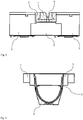
- FIG. 6 an inventive drainage system with a connecting element 3 according to an exemplary second embodiment is shown in a schematic sectional view.
- the connecting element 3 is rigid and has two stop elements 4, 4 ', which are arranged on the outer side of the end portions of the connecting element 3 and that at different distances from the respective end region. In particular, one distance is twice the other distance.
- the second embodiment essentially corresponds to the first embodiment, wherein, in the embodiment shown here, further no insulation means 5 is arranged around the rail.
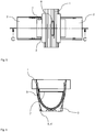
- FIG. 7 a drainage system according to the invention with a connecting element 3 according to the exemplary second embodiment is shown in a schematic side sectional view.
- the presentation corresponds essentially to the Presentation off FIG. 6 rotated 90 °.
- the asymmetrical arrangement of the stop elements 4, 4 ' can be clearly seen.
- a drainage channel 2 is first arranged laterally and transversely to the rail.
- the connecting element 3 is inserted under the rail in the drainage channel 2, here from right to left, until the first stop element 4 abuts the drainage channel 2.
- the first stop element 4 is arranged further away from the associated end region than the second stop element 4 'is arranged away from the other end region.
- a second drainage channel 2 is arranged correspondingly symmetrically to the first drainage channel 2 on the other side of the rail.
- the connecting element 3 is then moved opposite to the first direction of movement, in this case from left to right, until the second stop element 4 'abuts the second drainage channel 2.
- the rail 1 is located directly on the connecting element 3.
- a flat layer of an insulating means 5 is arranged between rail 1 and connecting element 3.
- a concreting and / or sealing is provided subsequent to the assembly.
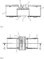
- FIG. 8 a drainage system according to the invention with a connecting element 3 according to the exemplary second embodiment is shown in a schematic plan view.
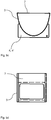
- FIGS. 9a to 9d a connection element 3 according to the invention according to an exemplary third embodiment is shown in various schematic views.
- FIG. 9a is a schematic perspective view of the connecting element 3 according to the third embodiment shown.
- the third embodiment corresponds essentially to the second embodiment, with the difference that the connecting element 3 upwards, ie in the direction of the rail 1, partially closed.
- the position of the opening is matched to the position of the drainage opening 8 in the rail and optionally the insulation means 5.
- the opening is larger than the drainage opening 8, to allow easy positioning.
- the cover is positive, non-positive or cohesive with the Connecting element 3 connected.
- the cover is formed integrally with the connecting element 3.
- FIGS. 9b to 9d correspond to different views of the connecting element 3 according to the third embodiment.
- connection element 3 according to the invention according to an exemplary fourth embodiment is shown in various schematic views.
- the fourth embodiment corresponds essentially to the third embodiment, but here two openings on the outer sides, ie in the end regions of the connecting element 3 are arranged.
- the rail has lateral drainage openings 8, so that the water is conducted into the connecting element 3 in the end regions.
- FIGS. 11a to 11d a closure flap 6 according to the invention is shown in various schematic views according to an exemplary embodiment.
- FIG. 11a is a perspective view of the flap 6 is shown.
- Such a closure flap is arranged on the end region of one or both drainage channels 2 facing away from the rail 1.
- the surface of the closure flap 6 is larger than the cross-sectional area of the end region of the drainage channels 2 to cover them well ..
- the drainage system serves as a formwork element and is secured against dirt entry or unintentional penetration of concrete and / or sealant. A functional impairment is meanwhile avoided.
- the closure flap 6 may additionally also have a sealing ring in order to seal the drainage channel even better.
- the surface of the closure flap 6 substantially corresponds to the cross section of the drainage channel 2.
- Such a closure flap 6 can also be attached to one or both sides of the connecting element 3.
- the closure flap 6 is alternatively materially connected to the drainage channel 2, for example glued or welded to this.
- FIGS. 12a to 12d a further closure flap 6 'according to the invention is shown in various schematic views according to an exemplary embodiment.
- the further closure flap 6 ' substantially corresponds to the closure flap 6, with the difference that the further closure flap 6' extends only in an upper area of the drainage channel 2 or the connecting element 3.
- the further closure flap 6 ' is arranged on an end region facing the rail 1 and has a resilient projection which is positively and / or non-positively connected to the rail 1 or a possible insulating means 5 is applied and thus seals the drainage system, in particular against liquid and foreign bodies.
- the further closure flap 6 ' serves as a formwork element for a concreting or sealing.
- the further closure flap 6 ' can also be fixedly arranged on the drainage channel 2 or the connecting element 3, for example it can be riveted or welded or glued thereto.
Landscapes
- Engineering & Computer Science (AREA)
- Architecture (AREA)
- Civil Engineering (AREA)
- Structural Engineering (AREA)
- Railway Tracks (AREA)
- Sink And Installation For Waste Water (AREA)
Description
- Die vorliegende Erfindung betrifft ein Entwässerungssystem für eine Schiene sowie ein Verfahren zur Montage eines solchen Entwässerungssystems.
- Schienen, beispielsweise Eisenbahnschienen, sammeln bedingt durch ihre Form bei Nässe Wasser in ihrer Mitte. Dies stellt für den Zugverkehr ein erhebliches Sicherheitsrisiko dar. Daher ist es von erheblicher Bedeutung, Wasser schnellstmöglich von dem Gleiskörper abzuleiten. Dazu weisen bekannte Schienen eine Entwässerung auf, bei der über Löcher in der Schiene Wasser in Entwässerungsgräben zu beiden Seiten der Schiene abgeleitet wird. Um ein Sammeln des Wassers im Bereich unter der Schiene zu vermeiden, werden die Entwässerungsgräben daher über eine nachträglich zu montierende Rinne verbunden. Derartige Entwässerungssysteme werden beispielsweise in den Druckschriften
WO 2013/017752 A1 ,EP 2 418 322 A2 ,DE 10 2007 024 606 A1 undDE 20 005 074 U1 offenbart. - Die Montage solcher Rinnen ist dabei schwierig, da der Bereich unterhalb der Schiene schlecht zugänglich ist und sichergestellt sein muss, dass die Rinne zu beiden Seiten an den Entwässerungsgräben anliegt, damit auftretendes Wasser nicht in den Boden zwischen Entwässerungsgräben und Rinne sickert oder sich dort staut.
- Nachteilig bei solchen Schienenentwässerungssystemen ist, dass geringe Fertigungstoleranzen einzuhalten sind, um eine Passgenauigkeit der Rinne in Bezug auf die Entwässerungsgräben zu gewährleisten. Ferner ist die Endmontage solcher Systeme mit erheblichem Aufwand verbunden.
- Es war daher die Aufgabe der vorliegenden Erfindung, ein Entwässerungssystem für eine Schiene sowie ein Verfahren zur Montage eines solchen Entwässerungssystems zur Verfügung zu stellen, die die Nachteile des Standes der Technik nicht aufweisen.
- Gelöst werden kann die Aufgabe mit einem Entwässerungssystem für eine Schiene, wobei das System zwei zu beiden Seiten der Schiene und vorzugsweise quer zu der Schiene angeordnete Entwässerungsrinnen umfasst und das System ein zur Verbindung der Entwässerungsrinnen vorgesehenes Verbindungselement umfasst, das unterhalb der Schiene angeordnet ist, dadurch gekennzeichnet, dass das Verbindungselement derart elastisch verformbar ausgebildet ist, dass es sich an die Form des inneren Querschnitts der Entwässerungsrinne anpasst.
- Dadurch ist es in vorteilhafter Weise möglich, ein Verbindungselement bereitzustellen, welches einfacher herzustellen ist, da es höhere Fertigungstoleranzen erlaubt, und dass eine einfache und dennoch passgenaue Montage erlaubt. Ferner ermöglicht das Entwässerungssystem eine optimale Entwässerung einer Schiene, da das Verbindungselement sich an den Querschnitt der Entwässerungsrinnen anpasst und somit automatisch den größtmöglichen Querschnitt realisiert. Selbst im Falle von durch Fertigungsungenauigkeiten bedingten, unterschiedlich großen Querschnitten der beiden Entwässerungsrinnen passt sich das Verbindungselement optimal an beide Entwässerungsrinnen an.
- Vorzugsweise sind die Entwässerungsrinnen jeweils gleich und/oder symmetrisch ausgebildet. Besonders bevorzugt sind die Entwässerungsrinnen aus Kunststoff gefertigt. Alternativ sind die Entwässerungsrinnen aus Beton, insbesondere aus Stahlbeton oder Polybeton, oder aus Stahl gefertigt. Ganz besonders bevorzugt weisen die Entwässerungsrinnen an ihrer Oberseite eine geschlossene oder wenigstens teilweise geöffnete Abdeckung auf. Hierdurch wird es ermöglicht, Fremdkörpern ein Eindringen in die Entwässerungsrinnen zumindest zu erschweren und so einen reibungslosen Abfluss des Wassers zu gewährleisten. Dem Fachmann ist klar, dass Wasser lediglich eine beispielhafte Flüssigkeit ist, die abgeleitet werden kann mit einem erfindungsgemäßen Entwässerungssystem. Jegliche andere Flüssigkeit ist ebenfalls denkbar, beispielsweise austretendes Öl.
- Vorzugsweise ist das Verbindungselement in radiale Richtung vorgespannt. Hierdurch wird ein besonders einfach herzustellendes Verbindungselement bereitgestellt. Eine Montage wird hierdurch vorteilhafterweise vereinfacht, da das Verbindungselement nur zusammengedrückt werden muss, insbesondere radial nach innen, und sich anschließend (nach Einbau) auf Grund seiner Vorspannung automatisch dem Querschnitt der Entwässerungsrinne anpasst. Dadurch wird ferner auf besonders vorteilhafte Weise eine dichte Verbindung zwischen Verbindungselement und Entwässerungsrinne ermöglicht.
- Dem Fachmann ist klar, dass das Verbindungselement vorzugsweise ebenfalls quer zu der Schiene angeordnet ist. Denkbar ist jedoch auch, dass das Verbindungselement etwas schräg zu der Schiene angeordnet ist, insbesondere um einen Versatz zwischen den Entwässerungsrinnen auszugleichen.
- Vorzugsweise weist das Verbindungselement einen Querschnitt auf, der im Wesentlichen dem Querschnitt der Entwässerungsrinnen entspricht. Besonders bevorzugt ist der Querschnittsumfang des Verbindungselements kleiner oder gleich groß wie der innere Querschnittsumfang der Entwässerungsrinne. Hierdurch wird in vorteilhafter Weise ein Verbindungselement bereitgestellt, welches nach Einbau nicht über die Entwässerungsrinne hinausragt und damit eine einfache Montage unter die Schiene ermöglicht.
- Vorzugsweise ist das Verbindungselement rinnenförmig ausgebildet. Hierdurch wird eine besonders gute Entwässerung durch einen in Haupterstreckungsrichtung im Wesentlichen gleichförmigen Querschnitt des Entwässerungssystems realisiert.
- Vorzugsweise ist das Verbindungselement nach Einbau überlappend mit den Entwässerungsrinnen angeordnet. Hierdurch werden vorteilhafterweise eine einfachere Montage und höhere Fertigungstoleranzen und damit eine einfachere Herstellung ermöglich.
- Vorzugsweise liegt das Verbindungselement nach Einbau form- und/oder kraftschlüssig an den Innenseiten der Entwässerungsrinnen an. Besonders bevorzugt wird das Verbindungselement nach Einbau stoffschlüssig mit den Entwässerungsrinnen verbunden, insbesondere verklebt oder verschweißt. Hierdurch wird die Dichtigkeit des Entwässerungssystems in vorteilhafter Weise verbessert. Alternativ weist das Verbindungselement und/oder die Entwässerungsrinnen ein Dichtelement auf, insbesondere eine Dichtlippe, das Verbindungselement und Entwässerungsrinne flüssigkeitsdicht verbindet.
- Die Schiene weist Entwässerungsöffnungen auf, beispielsweise in Form von Entwässerungsgräben und/oder Entwässerungslöchern, die in der Schiene seitlich und/oder senkrecht angeordnet sind. Hierdurch wird ein Abfluss des Wassers von der Schiene in das Entwässerungssystem ermöglicht. Durch die Anordnung der Entwässerungsöffnungen wird das Wasser vorzugsweise in Richtung wenigstens einer Entwässerungsrinne oder in Richtung des Verbindungselements abgeleitet.
- Vorzugsweise wird das Entwässerungssystem nach erfolgter Montage wenigstens teilweise einbetoniert und/oder von einer Dichtmasse umgeben. Hierdurch wird eine stabile Lagerung des Entwässerungssystems ermöglicht sowie eine Abdichtung gegen Schmutzeintrag oder das ungewollte Eindringen/Austreten von Flüssigkeiten aus dem Entwässerungssystem erreicht. Alternativ kann ein anderes, geeignetes Fixierungsmaterial gewählt werden, beispielsweise Kies oder Sand.
- Besonders bevorzugt ist die Dichtmasse ein Kunststoffmaterial, ganz besonders bevorzugt ein elektrisch nicht leitfähiges Kunststoffmaterial, noch mehr bevorzugt ein elastisches Kunststoffmaterial.
- Ferner wird die Aufgabe gelöst mit einem erfindungsgemäßen Entwässerungssystem für eine Schiene gemäß Anspruch 1. Besonders bevorzugt entspricht der Abstand des einen Anschlagselements zu dem nächstliegenden Endbereich dem Doppelten des Abstands des anderen Anschlagselements zu dem nächstliegenden Endbereich. Ganz besonders bevorzugt entspricht der Abstand des einen Anschlagselements zu dem nächstliegenden Endbereich dem Doppelten des gewünschten Überlappungsbereich des Verbindungselementes mit der jeweiligen Rinne und der Abstand des anderen Anschlagselements dem einfachen Überlappungsbereich des Verbindungselementes mit der Rinne.
- Dadurch ist es vorteilhaft möglich, ein stabiles Verbindungselement bereitzustellen, welches einfach und mit hohen Fertigungstoleranzen herstellbar ist. Durch die asymmetrische Anordnung der Anschlagselemente wird eine Montage ermöglicht.
- Vorzugsweise sind die Anschlagselemente einstückig mit dem Verbindungselement herstellbar, insbesondere durch ein Spritzgießverfahren. Alternativ sind die Anschlagselemente stoffschlüssig mit dem Verbindungselement verbunden, insbesondere über eine Schweißverbindung. Besonders bevorzugt sind die Anschlagselemente flächig ausgebildet, insbesondere als Standflächen. Hierdurch wird in vorteilhafter Weise zugleich eine sichere Positionierung des Verbindungselements gewährleistet, insbesondere eine drehfeste Positionierung. Vorzugsweise dienen im Falle einer Einbetonierung die Anschlagselemente als zusätzliche Armierungselemente.
- Vorzugsweise weist das Verbindungselement Vorsprünge auf, die federnd mit der Schiene zusammenwirken. Besonders bevorzugt wirken die Vorsprünge form- und/oder kraftschlüssig mit der Unterseite der Schiene zusammen. Der Fachmann versteht, dass statt der Unterseite der Schiene auch ein gegebenenfalls dort angeordnetes anderes Element gemeint ist. Hierdurch wird eine besonders genaue Positionierung des Verbindungselements ermöglicht.
- Vorzugsweise ist das Verbindungselement ein- oder mehrstückig ausgebildet. Hierdurch wird vorteilhafterweise ein einfach herstellbares Verbindungselement bereitgestellt..
- Vorzugsweise ist das Verbindungselement und/oder die Entwässerungsrinnen und/oder das Entwässerungssystem als Schalungselement vorgesehen. Hierdurch ist es vorteilhafterweise möglich, das Entwässerungssystem mit Beton und/oder einer Dichtmasse zu umgießen, ohne dass der Wasserabfluss behindert wird. Somit ist das System sicher im Boden verankerbar und/oder gegen äußere Einflüsse abdichtbar.
- Vorzugsweise weist das Verbindungselement und/oder die Entwässerungsrinnen einen im Wesentlichen parabelförmigen oder kreisbogenförmigen Querschnitt oder einen rechteckigen Querschnitt auf. Hierdurch wird vorteilhafterweise ein flexibles Entwässerungssystem bereitgestellt, dessen Querschnitt an die jeweilige Rinnenform anpassbar ist.
- Vorzugsweise ist das Verbindungselement in Richtung der Schiene wenigstens teilweise geschlossen und weist in Richtung der Schiene wenigstens eine Öffnung auf. Hierdurch ist es in vorteilhafter Weise möglich, ein Verbindungselement bereitzustellen, welches generell ein Eindringen von Fremdkörpern verhindert, aber dennoch ein erfindungsgemäßes Ableiten von Wasser gewährleistet. Zudem wird somit ein einfacherer Einbau ermöglicht. Besonders bevorzugt weist das Verbindungselement eine Abdeckung auf. Ganz besonders bevorzugt ist die Abdeckung lösbar mit dem Verbindungselement form- und/oder kraftschlüssig befestigt.
- Vorzugsweise weist das System ein Isolationsmittel auf, das insbesondere aus einem elektrischen Isolationsmaterial ausgebildet ist. Alternativ oder zusätzlich ist das Isolationsmittel aus einem thermischen und/oder akustischen Isolationsmaterial ausgebildet. Hierdurch werden in vorteilhafter Weise ein Kurzschluss und/oder eine Wärmebrücke und/oder eine ungewollte Verstärkung von Schallwellen ausgeschlossen.
- Besonders bevorzugt weist das Isolationsmittel Entwässerungslöcher auf. Ganz besonders bevorzugt ist das Isolationsmittel wenigstens teilweise um die Schiene herum angeordnet und insbesondere mit der Schiene form- und/oder kraft-, oder stoffschlüssig verbunden. Alternativ oder zusätzlich ist das Isolationsmittel kraft-, form- und/oder stoffschlüssig mit dem Verbindungselement verbunden ist. Hierdurch ist es vorteilhafterweise möglich, die Schiene elektrisch, akustisch und/oder thermisch von dem Entwässerungssystem zu entkoppeln und dennoch eine erfindungsgemäße Ableitung von Wasser zu ermöglichen. Durch eine Verbindung mit dem Verbindungselement ist eine besonders genaue Positionierung des Verbindungselements möglich, so dass beispielsweise die Lage von Entwässerungsöffnungen einer Abdeckung des Verbindungselements genau mit der Lage von Entwässerungsöffnungen des Isolationsmittels und/oder der Schiene übereinstimmt.
- Vorzugsweise weisen die Entwässerungsrinnen, oder wenigstens eine Entwässerungsrinne, an ihren von der Schiene abgewandten Endseiten eine Verschlussklappe auf. Hierdurch ist es in vorteilhafter Weise möglich, das Entwässerungssystem einzubetonieren oder mit einer Dichtmasse zu umgeben. Die Entwässerungsrinnen und/oder das Verbindungselement und/oder die Verschlussklappen können dabei als Armierungselemente fungieren. Die Verschlussklappen, die Rinne und/oder das Verbindungselement können als Schalungselemente dienen und verhindern insbesondere ein Eindringen des flüssigen Betons und/oder der Dichtmasse in die Entwässerungsrinnen und/oder in das Verbindungselement. Besonders bevorzugt decken die Verschlussklappen wenigstens die gesamte Querschnittfläche der Entwässerungsrinnen ab. Denkbar ist insbesondere, dass die Verschlussklappen eine größere Fläche als die Querschnittsfläche der Endseiten der Entwässerungsrinnen abdecken. Hierdurch wird eine besonders dichte Abdeckung ermöglicht. Zudem wird durch überstehende Vorsprünge der Verschlussklappen vorteilhafterweise eine bessere Verankerung in Beton und/oder Dichtmasse erreicht. Ganz besonders bevorzugt weisen die Verschlussklappen auf ihrer der Entwässerungsrinne zugewandten Seite eine Dichtung, insbesondere eine Dichtlippe auf, die vorzugsweise umlaufend ausgebildet ist und mit der Entwässerungsrinne abdichtend zusammenwirkt. Hierdurch wird die Dichtigkeit des Entwässerungssystems weiter gesteigert und ein Eindringen des Betons und/oder der Dichtmasse in die Entwässerungsrinne verhindert.
- Vorzugsweise weisen die Entwässerungsrinnen an ihren der Schiene zugewandten Endseiten weitere Verschlussklappen auf, wobei die weiteren Verschlussklappen insbesondere wenigstens einen oberen Teil des Querschnitts der Entwässerungsrinnen abdecken. Besonders bevorzugt weisen die weiteren Verschlussklappen der Schiene zugewandte federnde Vorsprünge auf, die insbesondere nach Einbau form- und/oder kraftschlüssig mit der Schiene zusammenwirken. Hierdurch ist es vorteilhafterweise möglich, die Entwässerungsrinnen auch auf ihrer Innenseite gegen Fremdkörper und/oder Flüssigkeit und/oder Beton und/oder Dichtmasse zu sichern. Eine Einbetonierung und/oder Abdichtung mit einer ganz oder teilweise um das Entwässerungssystem angeordneten Dichtmasse wird hierdurch ebenfalls ermöglicht ohne den Abfluss des Wassers zu behindern. Durch die Verschlussklappen und/oder weiteren Verschlussklappen wird eine besonders einfache Schalung bereitgestellt. Alternativ erfolgt eine gezielte Abdichtung mit Dichtmasse ausschließlich im Bereich der Verschlussklappen und/oder weiteren Verschlussklappen.
- Vorzugsweise weist auch das Verbindungselement an einem Ende oder an beiden Enden eine weitere Verschlussklappe und/oder ein Federelement auf. Hierdurch wird in vorteilhafter Weise ein Schmutzeintrag verhindert und/oder ein Schalungselement bereitgestellt. Das Federelement drückt die Verschlusskappe beispielweise gegen die Schiene und verbessert dadurch den Form- und/oder Reibschluss zwischen den beiden Elementen.
- Vorzugsweise weist die weitere Verschlussklappe eine wenigstens teilweise umlaufende Dichtung auf, insbesondere eine Dichtlippe. Hierdurch wird in vorteilhafter Weise eine Abdichtung des Entwässerungssystems im Bereich des Übergangs zwischen Verbindungselement und Entwässerungsrinne und/oder Schiene gegen Schmutzeintrag und/oder Eindringen von Beton und/oder Dichtmasse ermöglicht.
- Weiterhin kann die Aufgabe gelöst werden durch ein Verfahren zur Montage eines Entwässerungssystems für eine Schiene, wobei in einem ersten Schritt zu beiden Seiten der Schiene und vorzugsweise quer zu der Schiene zwei Entwässerungsrinnen angeordnet werden, wobei in einem zweiten Schritt der Querschnitt eines elastisch verformbaren Verbindungselements durch Kraftbeaufschlagung verringert wird und das Verbindungselement unterhalb der Schiene und quer zu der Schiene sowie wenigstens teilweise überlappend mit den Entwässerungsrinnen auf der Innenseite der Entwässerungsrinnen angeordnet wird, wobei in einem dritten Schritt die Kraftbeaufschlagung aufgehoben wird, so dass sich das Verbindungselement an die Form des inneren Querschnitts der Entwässerungsrinne anpasst.
- Hierdurch ist es in vorteilhafter Weise möglich, ein Entwässerungssystem in besonders einfacher Weise zu montieren. Durch die Querschnittsverringerung kann das Verbindungselement problemlos in die bestimmungsgemäße Position gebracht werden und nach Aufhebung der Kraftbeaufschlagung stellt sich eine dichte Verbindung zwischen Verbindungselement und Entwässerungsrinnen und gegebenenfalls auch Schiene her, ohne dass dafür weitere Schritte nötig wären. Durch Materialwahl und/oder Einstellung der Vorspannung ist die Festigkeit und/oder Dichtigkeit des Systems einstellbar. Bei einer starken Vorspannung liegt ein starker Kraftschluss zwischen Entwässerungsrinne und Verbindungselement vor, so dass diese ortsfest befestigt ist, ohne dass weitere Sicherungsschritte und/oder Sicherungsmittel notwendig sind.
- Vorzugsweise erfolgt der erste Schritt vor dem zweiten Schritt und/oder der zweite Schritt vor dem dritten Schritt.
- Vorzugsweise wird das Entwässerungssystem anschließend wenigstens teilweise einbetoniert und/oder von einer Dichtmasse umgeben.
- Vorzugsweise erfolgt die Kraftbeaufschlagung durch Zusammendrücken. Hierdurch ist eine besonders einfache Montage möglich, insbesondere eine werkzeuglose Montage.
- Vorzugsweise ist die Außenseite des Verbindungselementes nach Ausführung des dritten Schritts wenigstens teilweise mit der Innenseite der Entwässerungsrinnen form- und/oder kraftschlüssig verbunden.
- Weiterhin wird die Aufgabe gelöst durch ein erfindungsgemäßes Verfahren zur Montage eines Entwässerungssystems für eine Schiene, gemäß Anspruch 8.
- Hierdurch ist es in vorteilhafter Weise möglich, ein einfaches Montageverfahren bereitzustellen. Durch die asymmetrisch angeordneten Anschlagselemente wird eine sichere und korrekte Positionierung des Verbindungselements auf einfache Weise ermöglicht. Eine Sichtprüfung von beiden Seiten aus und/oder eine Nachjustierung ist vorteilhafterweise unnötig. Vorteilhafterweise kann ein stabiles Verbindungselement verwendet werden. Zudem wird es vorteilhafterweise ermöglicht, dass nach erfolgter Montage der Überlapp des Verbindungselement mit beiden Entwässerungsrinnen gleich groß ist.
- Vorzugsweise erfolgt der erste Schritt vor dem zweiten Schritt und/oder der zweite Schritt vor dem dritten Schritt und/oder der dritte Schritt vor dem vierten Schritt.
- Vorzugsweise erfolgt in dem zweiten Schritt die Bewegung des Verbindungselements im Wesentlichen parallel zu der Haupterstreckungsrichtung der Entwässerungsrinne und besonders bevorzugt erfolgt in dem vierten Schritt die Bewegung des Verbindungselements im Wesentlichen antiparallel zu der Haupterstreckungsrichtung der Entwässerungsrinne, also insbesondere entgegengesetzt zu der Bewegung in dem zweiten Schritt.
- Vorzugsweise wird das Verbindungselement in dem zweiten Schritt mit der Seite an der der Abstand zwischen Endbereich und Anschlagselement größer ist in die Entwässerungsrinne eingeführt.
- Vorzugsweise wird das Entwässerungssystem anschließend wenigstens teilweise einbetoniert und/oder von einer Dichtmasse umgeben.
- Die angesprochenen möglichen Ausführungsformen sind grundsätzlich auf jedes erfindungsgemäße Entwässerungssystem und/oder auf jedes erfindungsgemäße Verfahren anwendbar.
- Im Folgenden wird die Erfindung anhand der
Figuren 6 bis 12 erläutert. Diese Erläuterungen sind lediglich beispielhaft und schränken den allgemeinen Erfindungsgedanken nicht ein. - Figur 1
- zeigt ein Verbindungselement gemäß einer beispielhaften ersten Ausführungsform in einer schematischen Schnittzeichnung.
- Figur 2
- zeigt ein Verbindungselement gemäß der beispielhaften ersten Ausführungsform in einer schematischen Perspektivansicht.
- Figur 3
- zeigt ein Entwässerungssystem mit einem Verbindungselement gemäß der beispielhaften ersten Ausführungsform in einer schematischen seitlichen Schnittzeichnung.
- Figur 4
- zeigt ein Entwässerungssystem mit einem Verbindungselement gemäß der beispielhaften ersten Ausführungsform in einer schematischen Schnittzeichnung.
- Figur 5
- zeigt ein Entwässerungssystem mit einem Verbindungselement gemäß der beispielhaften ersten Ausführungsform in einer schematischen Aufsicht.
- Figur 6
- zeigt ein erfindungsgemäßes Entwässerungssystem mit einem Verbindungselement gemäß einer beispielhaften zweiten Ausführungsform in einer schematischen Schnittzeichnung.
- Figur 7
- zeigt ein erfindungsgemäßes Entwässerungssystem mit einem Verbindungselement gemäß der beispielhaften zweiten Ausführungsform in einer schematischen seitlichen Schnittzeichnung.
- Figur 8
- zeigt ein erfindungsgemäßes Entwässerungssystem mit einem Verbindungselement gemäß der beispielhaften zweiten Ausführungsform in einer schematischen Aufsicht.
- Figuren 9a bis 9d
- zeigen ein erfindungsgemäßes Verbindungselement gemäß einer beispielhaften dritten Ausführungsform in verschiedenen schematischen Ansichten.
- Figuren 10a bis 10d
- zeigen ein erfindungsgemäßes Verbindungselement gemäß einer beispielhaften vierten Ausführungsform in verschiedenen schematischen Ansichten.
- Figuren 11a bis 11d
- zeigen eine erfindungsgemäße Verschlussklappe gemäß einer beispielhaften Ausführungsform in verschiedenen schematischen Ansichten.
- Figuren 12a bis 12d
- zeigen eine erfindungsgemäße weitere Verschlussklappe gemäß einer beispielhaften Ausführungsform in verschiedenen schematischen Ansichten.
- In
Figur 1 ist ein Verbindungselement 3 gemäß einer beispielhaften ersten Ausführungsform in einer schematischen Schnittzeichnung dargestellt. Das Verbindungselement 3 ist beispielsweise aus Federstahl oder Kunststoff gefertigt und weist einen im Wesentlichen kreisbogenförmigen Querschnitt auf. Es ist elastisch verformbar ausgebildet. In der dargestellten ersten Ausführungsform ist das Verbindungselement 3 nach außen vorgespannt. An den Oberkanten weist das Verbindungselement 3 federnd ausgebildete Vorsprünge auf. - In
Figur 2 ist ein Verbindungselement 3 gemäß der beispielhaften ersten Ausführungsform in einer schematischen Perspektivansicht dargestellt. Es ist zu sehen, dass das Verbindungselement 3 im Wesentlich die Form eines halben Hohlzylinders, also eine Rinnenform aufweist. Die federnden Vorsprünge sind einstückig mit dem Verbindungselement 3 ausgebildet, erstrecken sich jedoch nicht über die gesamte Länge des Verbindungselements 3. Alternativ sind auch eine Vielzahl von einzelnen federnden Vorsprüngen denkbar. - In
Figur 3 ist ein Entwässerungssystem mit einem Verbindungselement 3 gemäß der beispielhaften ersten Ausführungsform in einer schematischen seitlichen Schnittzeichnung dargestellt. Das Verbindungselement 3 entspricht dabei dem in denFiguren 1 und 2 gezeigten Verbindungselement 3. Quer zu der Haupterstreckungsrichtung einer Schiene 1, die hier senkrecht zu der Zeichenebene verläuft, sind zwei Entwässerungsrinnen 2 angeordnet, jeweils eine Entwässerungsrinne 2 zu beiden Seite der Schiene 1. Um die Schiene ist ein Isolationsmittel 5 formschlüssig oder stoffschlüssig angeordnet, das das Entwässerungssystem, also im Wesentlichen das Verbindungselement 3 und die Entwässerungsrinnen 2 von der Schiene 1 elektrisch isoliert. Alternativ oder zusätzlich dient das Isolationsmittel 5 der mechanischen, akustischen oder thermischen Isolation, oder einer beliebigen Kombination davon. So kann das Isolationsmittel 5 einen elektrischen Kurzschluss verhindern, oder eine Beschädigung des Entwässerungssystems durch Vibrationen ausschließen. Dazu weist das Isolationsmittel 5 Dämpfungseigenschaften auf. Die Entwässerungsrinnen 2 weisen im Wesentlichen ebenfalls einen kreisbogenförmigen Querschnitt auf. Das Verbindungselement 3 ist derart unter der Schiene 1 und zwischen den Entwässerungsrinnen 2 angeordnet, dass es die Entwässerungsrinnen 2 verbindet. Das vorgespannte Verbindungselement 3 wird dazu zusammengedrückt und zwischen die Entwässerungsrinnen 2 so eingebracht, dass es mit beiden Entwässerungsrinnen 2 einen Überlapp bildet. Anschließend wird es losgelassen. Durch seine Vorspannung passt es sich in seiner Form dem inneren Querschnitt der Entwässerungsrinnen 2 an. Die federnden Vorsprünge liegen dann form- und kraftschlüssig an dem Isolationsmittel 5 an. Regnet es beispielsweise, oder sammelt sich aus anderen Gründen Wasser oder eine andere Flüssigkeit in der Schiene 1, so fließt dieses durch entsprechende, hier senkrecht angeordnete, Entwässerungsöffnungen 8 in der Schiene 1 und in dem Isolationsmittel 5 in das Verbindungselement 3 ab und wird von dort aus über die Entwässerungsrinnen 2 nach außen abgeleitet. Die Entwässerungsrinnen 2 weisen eine Abdeckung auf, um ein Eindringen von Fremdkörpern und damit möglicherweise ein Verstopfen der Entwässerungsrinnen 2 zu verhindern. Das Verbindungselement 3 ist halb so hoch wie eine Entwässerungsrinne 2. Alternativ sind auch beliebige andere Größenverhältnisse denkbar, wobei jedoch das Verbindungselement 3 niedriger ist als die Entwässerungsrinnen 2, damit es bei der Montage in diese eingeführt werden kann und damit es unterhalb der Schiene anordenbar ist. Das Entwässerungssystem wird nach erfolgter Montage wenigstens teilweise mit Beton umgossen und/oder mit einer Dichtmasse wenigstens teilweise umgeben beziehungsweise abgedichtet. Denkbar ist beispielsweise, dass die Dichtmasse großflächig an Verbindungsstellen angeordnet wird oder an Öffnungen, die nicht zum erfindungsgemäßen Ableiten des Wassers dienen. Auf diese Weise dient das Entwässerungssystem als Schalungselement. - In
Figur 4 ist ein Entwässerungssystem mit einem Verbindungselement 3 gemäß der beispielhaften ersten Ausführungsform in einer schematischen Schnittzeichnung dargestellt. Die Darstellung entspricht im Wesentlichen einer um 90° gedrehten Darstellung ausFigur 3 . Es sind Standfüße an den Entwässerungsrinnen 2 zu erkennen, die dazu dienen, die Entwässerungsrinnen 2 lagerichtig zu positionieren. Außerdem dienen die Standfüße als Armierungselemente für eine mögliche Einbetonierung. - In
Figur 5 ist ein Entwässerungssystem mit einem Verbindungselement 3 gemäß der beispielhaften ersten Ausführungsform in einer schematischen Aufsicht dargestellt. Die Schnittlinie C-C entspricht dabei der gewählten Schnittlinie inFigur 3 . Die Entwässerungsöffnung 8 erstreckt sich über die gesamte Breite des Verbindungselements 3. Alternativ ist auch eine geringere Erstreckung denkbar. Auch hier ist der beidseitige Überlapp des Verbindungselements 3 mit den Entwässerungsrinnen 2 deutlich zu erkennen. - In
Figur 6 ist ein erfindungsgemäßes Entwässerungssystem mit einem Verbindungselement 3 gemäß einer beispielhaften zweiten Ausführungsform in einer schematischen Schnittzeichnung dargestellt. Das Verbindungselement 3 ist dabei starr ausgebildet und weist zwei Anschlagselemente 4, 4' auf, die auf der Außenseite der Endbereiche des Verbindungselements 3 angeordnet sind und zwar in unterschiedlichen Entfernungen von dem jeweiligen Endbereich. Insbesondere beträgt die eine Entfernung das Doppelte der anderen Entfernung. Abgesehen von dem Verbindungselement 3 entspricht die zweite Ausführungsform im Wesentlichen der ersten Ausführungsform, wobei in der hier dargestellten Ausführungsform ferner kein Isolationsmittel 5 um die Schiene herum angeordnet ist. - In
Figur 7 ist ein erfindungsgemäßes Entwässerungssystem mit einem Verbindungselement 3 gemäß der beispielhaften zweiten Ausführungsform in einer schematischen seitlichen Schnittzeichnung dargestellt. Die Darstellung entspricht dabei im Wesentlichen der Darstellung ausFigur 6 , um 90° gedreht. Die asymmetrische Anordnung der Anschlagselemente 4, 4' ist gut zu erkennen. Bei der Montage wird zunächst seitlich und quer zu der Schiene eine Entwässerungsrinne 2 angeordnet. Dann wird das Verbindungselement 3 unter der Schiene in die Entwässerungsrinne 2 eingeführt, hier von rechts nach links, bis das erste Anschlagselement 4 an die Entwässerungsrinne 2 anstößt. Das erste Anschlagselement 4 ist dabei weiter von dem zugehörigen Endbereich entfernt angeordnet als das zweite Anschlagselement 4' von dem anderen Endbereich entfernt angeordnet ist. Nach dem Anstoßen des ersten Anschlagselements 4 an die Entwässerungsrinne 2 wird entsprechend symmetrisch zu der ersten Entwässerungsrinne 2 auf der anderen Seite der Schiene eine zweite Entwässerungsrinne 2 angeordnet. Das Verbindungselement 3 wird sodann entgegengesetzt zu der ersten Bewegungsrichtung bewegt, hier also von links nach rechts, bis das zweite Anschlagselement 4' an die zweite Entwässerungsrinne 2 anstößt. Die Anschlagselemente 4, 4' sind derart angeordnet, dass es erneut ein Überlapp zwischen Verbindungselement 3 und Entwässerungsrinnen 2 entsteht. Wenn die Abstände der Anschlagselemente 4, 4' zu den jeweiligen Endbereichen des Verbindungselements 3 derart gewählt sind, dass der eine Abstand gleich dem Doppelten des zweiten Abstands entspricht, wird nach erfolgter Montage der Überlapp zwischen den Entwässerungsrinnen 2 und dem Verbindungselement 3 symmetrisch, also auf beiden Seiten gleich sein. Die Schiene 1 liegt direkt auf dem Verbindungselement 3 auf. Alternativ ist zwischen Schiene 1 und Verbindungselement 3 eine flache Schicht eines Isolationsmittels 5 angeordnet. Auch gemäß dieser Ausführungsform ist anschließend an die Montage eine Einbetonierung und/oder Abdichtung vorgesehen. - In
Figur 8 ist ein erfindungsgemäßes Entwässerungssystem mit einem Verbindungselement 3 gemäß der beispielhaften zweiten Ausführungsform in einer schematischen Aufsicht dargestellt. Hier ist die Schnittlinie C-C gemäß der Darstellung ausFigur 7 gezeigt. - In den
Figuren 9a bis 9d ist ein erfindungsgemäßes Verbindungselement 3 gemäß einer beispielhaften dritten Ausführungsform in verschiedenen schematischen Ansichten dargestellt. InFigur 9a ist eine schematische Perspektivansicht des Verbindungselements 3 gemäß der dritten Ausführungsform dargestellt. Die dritte Ausführungsform entspricht dabei im Wesentlichen der zweiten Ausführungsform, mit dem Unterschied, dass das Verbindungselement 3 nach oben, also in Richtung der Schiene 1, teilweise geschlossen ist. Die Position der Öffnung ist dabei auf die Position der Entwässerungsöffnung 8 in der Schiene und gegebenenfalls dem Isolationsmittel 5 abgestimmt. Die Öffnung ist größer als die Entwässerungsöffnung 8, um eine einfache Positionierung zu ermöglichen. Gemäß der dargestellten Ausführungsform ist die Abdeckung form-, kraft- oder stoffschlüssig mit dem Verbindungselement 3 verbunden. Alternativ ist die Abdeckung einstückig mit dem Verbindungselement 3 ausgebildet. DieFiguren 9b bis 9d entsprechen dabei verschiedenen Ansichten des Verbindungselements 3 gemäß der dritten Ausführungsform. - In den
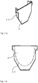
Figuren 10a bis 10d ist ein erfindungsgemäßes Verbindungselement 3 gemäß einer beispielhaften vierten Ausführungsform in verschiedenen schematischen Ansichten dargestellt. Die vierte Ausführungsform entspricht dabei im Wesentlichen der dritten Ausführungsform, wobei hier jedoch zwei Öffnungen an den Außenseiten, also in den Endbereichen, des Verbindungselements 3 angeordnet sind. In diesem Fall weist die Schiene seitliche Entwässerungsöffnungen 8 auf, so dass das Wasser in den Endbereichen in das Verbindungselement 3 geleitet wird. - In den
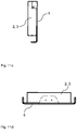
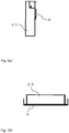
Figuren 11a bis 11d ist eine erfindungsgemäße Verschlussklappe 6 gemäß einer beispielhaften Ausführungsform in verschiedenen schematischen Ansichten dargestellt. InFigur 11a ist eine perspektivische Ansicht der Verschlussklappe 6 gezeigt. Eine solche Verschlussklappe ist an dem der Schiene 1 abgewandten Endbereich einer oder beider Entwässerungsrinnen 2 angeordnet. Die Fläche der Verschlussklappe 6 ist größer als die Querschnittsfläche des Endbereichs der Entwässerungsrinnen 2 um diese gut abzudecken.. Dadurch dient das Entwässerungssystem als Schalungselement und ist gegen Schmutzeintrag oder ungewolltes Eindringen von Beton und/oder Dichtmasse gesichert. Eine Funktionsbeeinträchtigung wird derweil vermieden. In den dargestellten Ansichten ist zur besseren Übersichtlichkeit jeweils nur ein Teil einer Entwässerungsrinne 2 dargestellt. Die Verschlussklappe 6 kann zusätzlich auch einen Dichtring aufweisen, um die Entwässerungsrinne noch besser abzudichten. Alternativ ist auch denkbar, dass die Fläche der Verschlussklappe 6 im Wesentlichen dem Querschnitt der Entwässerungsrinne 2 entspricht. Auch ist eine solche Verschlussklappe 6 an einer oder an beiden Seiten des Verbindungselements 3 anbringbar. Die Verschlussklappe 6 ist alternativ stoffschlüssig mit der Entwässerungsrinne 2 verbunden, beispielsweise an diese angeklebt oder angeschweißt. - In den
Figuren 12a bis 12d ist eine erfindungsgemäße weitere Verschlussklappe 6' gemäß einer beispielhaften Ausführungsform in verschiedenen schematischen Ansichten dargestellt. Die weitere Verschlussklappe 6' entspricht im Wesentlichen der Verschlussklapp 6, mit dem Unterschied, dass die weitere Verschlussklappe 6' sich nur in einem oberen Bereich der Entwässerungsrinne 2 oder des Verbindungselements 3 erstreckt. Die weitere Verschlussklappe 6' wird an einem der Schiene 1 zugewandten Endbereich angeordnet und weist einen federnden Vorsprung auf, welcher form- und/oder kraftschlüssig an der Schiene 1 oder einem eventuellen Isolationsmittel 5 anliegt und das Entwässerungssystem somit abdichtet, insbesondere gegen Flüssigkeit und Fremdkörper. Auch die weitere Verschlussklappe 6' dient als Schalungselement für eine Betonierung beziehungsweise Abdichtung. Die weitere Verschlussklappe 6' kann auch fest an der Entwässerungsrinne 2 oder dem Verbindungselement 3 angeordnet sein, beispielsweise kann es damit vernietet oder verschweißt oder angeklebt sein. -
- 1
- - Schiene
- 2
- - Entwässerungsrinne(n)
- 3
- - Verbindungselement
- 4, 4'
- - Anschlagselemente
- 5
- - Isolationsmittel
- 6
- - Verschlussklappen
- 6'
- - weitere Verschlussklappen
- 7
- - Abdeckelement
- 8
- - Entwässerungsöffnung
Claims (8)
- System aufweisend ein Entwässerungssystem und eine Schiene (1), wobei das Entwässerungssystem zwei zu beiden Seiten der Schiene (1) und vorzugsweise quer zu der Schiene (1) angeordnete Entwässerungsrinnen (2) umfasst und das Entwässerungssystem ein zur Verbindung der Entwässerungsrinnen (2) vorgesehenes Verbindungselement (3) umfasst, das unterhalb der Schiene (1) angeordnet ist, dadurch gekennzeichnet, dass das Verbindungselement (3) an seiner Außenseite zwei Anschlagselemente (4,4') aufweist, die jeweils im Endbereich des Verbindungselements (3) vorgesehen sind und der Abstand des jeweiligen Anschlagselements (4, 4') von dem jeweiligen Endbereich des Verbindungselements (3) jeweils unterschiedlich ist.
- System nach Anspruch 1, dadurch gekennzeichnet, dass das Verbindungselement (3) Vorsprünge aufweist, die federnd mit der Schiene (1) zusammenwirken.
- System nach einem der vorhergehenden Ansprüche, dadurch gekennzeichnet, dass das Verbindungselement (3) ein- oder mehrstückig ausgebildet ist.
- System nach einem der vorhergehenden Ansprüche, dadurch gekennzeichnet, dass das Verbindungselement (3) und/oder die Entwässerungsrinnen (2) einen im Wesentlichen parabelförmigen oder kreisbogenförmigen Querschnitt oder einen rechteckigen Querschnitt aufweist.
- System nach einem der vorhergehenden Ansprüche, dadurch gekennzeichnet, dass das Verbindungselement (3) in Richtung der Schiene (1) wenigstens teilweise geschlossen ist und in Richtung der Schiene (1) wenigstens eine Öffnung aufweist.
- System nach einem der vorhergehenden Ansprüche, dadurch gekennzeichnet, dass das Entwässerungssystem ein Isolationsmittel (5) aufweist, das aus einem elektrischen Isolatormaterial ausgebildet ist, wobei insbesondere das Isolationsmittel (5) Entwässerungslöcher aufweist, wobei das Isolationsmittel (5) wenigstens teilweise um die Schiene (1) herum angeordnet und mit der Schiene (1) form-, kraft-, oder stoffschlüssig verbunden ist, und/oder wobei das Isolationsmittel (5) kraft-, form- und/oder stoffschlüssig mit dem Verbindungselement (3) verbunden ist.
- System nach einem der vorhergehenden Ansprüche, dadurch gekennzeichnet, dass die Entwässerungsrinnen (2) an ihren von der Schiene (1) abgewandten Endseiten eine Verschlussklappe (6) aufweisen, wobei die Verschlussklappen (6) um eine Rotationsachse (A) drehbar gelagert sind, wobei die Verschlussklappen (6) wenigstens die gesamte Querschnittfläche der Entwässerungsrinnen (2) abdecken, und/oder dass die Entwässerungsrinnen (2) an ihren der Schiene (1) zugewandten Endseiten weitere Verschlussklappen (6') aufweisen, wobei die weiteren Verschlussklappen (6') wenigstens einen oberen Teil des Querschnitts der Entwässerungsrinnen (2) abdecken.
- Verfahren zur Montage eines Entwässerungssystems für eine Schiene (1), insbesondere nach einem der vorhergehenden Ansprüche, wobei in einem ersten Schritt zu beiden Seiten der Schiene (1) und quer zu der Schiene (1) zwei Entwässerungsrinnen (2) angeordnet werden, wobei in einem zweiten Schritt das Verbindungselement bis zu einem formschlüssigen Kontakt eines ersten Anschlagselements (4) des Verbindungselements mit einer Entwässerungsrinne (2) in die Entwässerungsrinne (2) eingeführt wird, wobei in einem dritte Schritt das Verbindungselement bis zu einem formschlüssigen Kontakt eines zweiten Anschlagselements (4') des Verbindungselements mit der zweiten Entwässerungsrinne (2) in die zweite Entwässerungsrinne (2) eingeführt wird.
Applications Claiming Priority (1)
| Application Number | Priority Date | Filing Date | Title |
|---|---|---|---|
| DE201310206602 DE102013206602A1 (de) | 2013-04-12 | 2013-04-12 | Entwässerungssystem für eine Schiene |
Publications (2)
| Publication Number | Publication Date |
|---|---|
| EP2789736A1 EP2789736A1 (de) | 2014-10-15 |
| EP2789736B1 true EP2789736B1 (de) | 2019-06-26 |
Family
ID=50478236
Family Applications (1)
| Application Number | Title | Priority Date | Filing Date |
|---|---|---|---|
| EP14163864.3A Active EP2789736B1 (de) | 2013-04-12 | 2014-04-08 | Entwässerungssystem für eine Schiene |
Country Status (2)
| Country | Link |
|---|---|
| EP (1) | EP2789736B1 (de) |
| DE (1) | DE102013206602A1 (de) |
Citations (1)
| Publication number | Priority date | Publication date | Assignee | Title |
|---|---|---|---|---|
| DE4340787A1 (de) * | 1993-11-23 | 1995-05-24 | Frenzel Otto Bauunternehmen | Vorrichtung zum Auffangen von Schadstoffen im Schienenbereich |
Family Cites Families (4)
| Publication number | Priority date | Publication date | Assignee | Title |
|---|---|---|---|---|
| DE20005074U1 (de) * | 2000-03-20 | 2000-06-29 | Hauraton Betonwarenfabrik GmbH & Co KG, 76437 Rastatt | Schienenentwässerungssystem |
| DE102007024606B4 (de) * | 2006-06-03 | 2009-11-05 | Hauraton Gmbh & Co. Kg | Entwässerungsvorrichtung |
| DE202010008256U1 (de) * | 2010-08-10 | 2010-11-04 | Hauraton Gmbh & Co. Kg | Entwässerungsrinne |
| FR2978777B1 (fr) * | 2011-08-04 | 2013-09-06 | Aco Produits Polymeres | Caniveau pour voie ferree de tramway |
-
2013
- 2013-04-12 DE DE201310206602 patent/DE102013206602A1/de not_active Withdrawn
-
2014
- 2014-04-08 EP EP14163864.3A patent/EP2789736B1/de active Active
Patent Citations (1)
| Publication number | Priority date | Publication date | Assignee | Title |
|---|---|---|---|---|
| DE4340787A1 (de) * | 1993-11-23 | 1995-05-24 | Frenzel Otto Bauunternehmen | Vorrichtung zum Auffangen von Schadstoffen im Schienenbereich |
Also Published As
| Publication number | Publication date |
|---|---|
| DE102013206602A1 (de) | 2014-10-30 |
| EP2789736A1 (de) | 2014-10-15 |
Similar Documents
| Publication | Publication Date | Title |
|---|---|---|
| EP2596557A2 (de) | Rahmen für einen schrank, insbesondere für einen schaltschrank | |
| EP2418322B1 (de) | Entwässerungsrinne | |
| EP3047070B1 (de) | Elektrisch isolierende unterlegplatte zur schienenbesfestigung | |
| WO2014207252A1 (de) | System zur herstellung eines türrahmens mit schwellenhalter | |
| EP3130739B2 (de) | Schwelle mit zusatzvorrichtung zur verringerung der barrierewirkung | |
| DE102009007442A1 (de) | Brücke oder Brückenabschnitt | |
| EP2789736A1 (de) | Entwässerungssystem für eine Schiene | |
| DE102007024606A1 (de) | Entwässerungsvorrichtung | |
| EP3485089A1 (de) | Dämpfungsanordnung für gleise | |
| WO2021047960A1 (de) | Entwässerungsvorrichtung | |
| EP3597834B1 (de) | Bauteil für eine ablaufvorrichtung für ein flachdach mit attika | |
| EP2108739B1 (de) | System für den Strassenbau zum Verschluss von Fugen | |
| DE102014119087B3 (de) | Oberteil eines Ablaufes für eine Oberflächenentwässerung | |
| EP2194190B1 (de) | Dehnfugen-Überbrückungsvorrichtung | |
| WO2018162373A1 (de) | Dichtungsprofil zum dichten einer karosserieöffnung eines kraftfahrzeugs sowie karosserieanordnung mit einer verschliessbaren karosserieöffnung | |
| EP1719848A2 (de) | Entwässerungsrinne aus Rinnenelementen | |
| DE202015104176U1 (de) | Zusatzvorrichtung zur Verringerung der Barrierewirkung einer Schwelle | |
| EP3420149B1 (de) | Anschlusseinrichtung zwischen rinne und sinkkasten | |
| EP1432880B1 (de) | Entwässerungseinrichtung | |
| DE202013101195U1 (de) | Fahrbahnübergang | |
| EP3763880B1 (de) | Vorrichtung zum vorzugsweise bündigen einbau in die strassen-/fahrbahndecke | |
| WO2005012661A1 (de) | Oberflächenentwässerungseinrichtung | |
| EP3784835B1 (de) | Anschlussvorrichtung, ablaufsystem und verfahren | |
| DE102013103654A1 (de) | Verbindungseinrichtung zum im Wesentlichen dichten Verbinden eines ersten Kanalelements mit einem zweiten Kanalelement eines Kanals | |
| EP1930512A2 (de) | Vorrichtung zum Einbau in eine Rohrleitung |
Legal Events
| Date | Code | Title | Description |
|---|---|---|---|
| PUAI | Public reference made under article 153(3) epc to a published international application that has entered the european phase |
Free format text: ORIGINAL CODE: 0009012 |
|
| 17P | Request for examination filed |
Effective date: 20140408 |
|
| AK | Designated contracting states |
Kind code of ref document: A1 Designated state(s): AL AT BE BG CH CY CZ DE DK EE ES FI FR GB GR HR HU IE IS IT LI LT LU LV MC MK MT NL NO PL PT RO RS SE SI SK SM TR |
|
| AX | Request for extension of the european patent |
Extension state: BA ME |
|
| R17P | Request for examination filed (corrected) |
Effective date: 20150415 |
|
| RBV | Designated contracting states (corrected) |
Designated state(s): AL AT BE BG CH CY CZ DE DK EE ES FI FR GB GR HR HU IE IS IT LI LT LU LV MC MK MT NL NO PL PT RO RS SE SI SK SM TR |
|
| STAA | Information on the status of an ep patent application or granted ep patent |
Free format text: STATUS: EXAMINATION IS IN PROGRESS |
|
| 17Q | First examination report despatched |
Effective date: 20170811 |
|
| GRAP | Despatch of communication of intention to grant a patent |
Free format text: ORIGINAL CODE: EPIDOSNIGR1 |
|
| STAA | Information on the status of an ep patent application or granted ep patent |
Free format text: STATUS: GRANT OF PATENT IS INTENDED |
|
| INTG | Intention to grant announced |
Effective date: 20190213 |
|
| GRAS | Grant fee paid |
Free format text: ORIGINAL CODE: EPIDOSNIGR3 |
|
| GRAA | (expected) grant |
Free format text: ORIGINAL CODE: 0009210 |
|
| STAA | Information on the status of an ep patent application or granted ep patent |
Free format text: STATUS: THE PATENT HAS BEEN GRANTED |
|
| AK | Designated contracting states |
Kind code of ref document: B1 Designated state(s): AL AT BE BG CH CY CZ DE DK EE ES FI FR GB GR HR HU IE IS IT LI LT LU LV MC MK MT NL NO PL PT RO RS SE SI SK SM TR |
|
| REG | Reference to a national code |
Ref country code: GB Ref legal event code: FG4D Free format text: NOT ENGLISH |
|
| REG | Reference to a national code |
Ref country code: CH Ref legal event code: EP |
|
| REG | Reference to a national code |
Ref country code: AT Ref legal event code: REF Ref document number: 1148419 Country of ref document: AT Kind code of ref document: T Effective date: 20190715 |
|
| REG | Reference to a national code |
Ref country code: DE Ref legal event code: R096 Ref document number: 502014012047 Country of ref document: DE |
|
| REG | Reference to a national code |
Ref country code: IE Ref legal event code: FG4D Free format text: LANGUAGE OF EP DOCUMENT: GERMAN |
|
| REG | Reference to a national code |
Ref country code: NL Ref legal event code: MP Effective date: 20190626 |
|
| PG25 | Lapsed in a contracting state [announced via postgrant information from national office to epo] |
Ref country code: NO Free format text: LAPSE BECAUSE OF FAILURE TO SUBMIT A TRANSLATION OF THE DESCRIPTION OR TO PAY THE FEE WITHIN THE PRESCRIBED TIME-LIMIT Effective date: 20190926 Ref country code: AL Free format text: LAPSE BECAUSE OF FAILURE TO SUBMIT A TRANSLATION OF THE DESCRIPTION OR TO PAY THE FEE WITHIN THE PRESCRIBED TIME-LIMIT Effective date: 20190626 Ref country code: FI Free format text: LAPSE BECAUSE OF FAILURE TO SUBMIT A TRANSLATION OF THE DESCRIPTION OR TO PAY THE FEE WITHIN THE PRESCRIBED TIME-LIMIT Effective date: 20190626 Ref country code: HR Free format text: LAPSE BECAUSE OF FAILURE TO SUBMIT A TRANSLATION OF THE DESCRIPTION OR TO PAY THE FEE WITHIN THE PRESCRIBED TIME-LIMIT Effective date: 20190626 Ref country code: SE Free format text: LAPSE BECAUSE OF FAILURE TO SUBMIT A TRANSLATION OF THE DESCRIPTION OR TO PAY THE FEE WITHIN THE PRESCRIBED TIME-LIMIT Effective date: 20190626 Ref country code: LT Free format text: LAPSE BECAUSE OF FAILURE TO SUBMIT A TRANSLATION OF THE DESCRIPTION OR TO PAY THE FEE WITHIN THE PRESCRIBED TIME-LIMIT Effective date: 20190626 |
|
| REG | Reference to a national code |
Ref country code: LT Ref legal event code: MG4D |
|
| PG25 | Lapsed in a contracting state [announced via postgrant information from national office to epo] |
Ref country code: GR Free format text: LAPSE BECAUSE OF FAILURE TO SUBMIT A TRANSLATION OF THE DESCRIPTION OR TO PAY THE FEE WITHIN THE PRESCRIBED TIME-LIMIT Effective date: 20190927 Ref country code: BG Free format text: LAPSE BECAUSE OF FAILURE TO SUBMIT A TRANSLATION OF THE DESCRIPTION OR TO PAY THE FEE WITHIN THE PRESCRIBED TIME-LIMIT Effective date: 20190926 Ref country code: RS Free format text: LAPSE BECAUSE OF FAILURE TO SUBMIT A TRANSLATION OF THE DESCRIPTION OR TO PAY THE FEE WITHIN THE PRESCRIBED TIME-LIMIT Effective date: 20190626 Ref country code: LV Free format text: LAPSE BECAUSE OF FAILURE TO SUBMIT A TRANSLATION OF THE DESCRIPTION OR TO PAY THE FEE WITHIN THE PRESCRIBED TIME-LIMIT Effective date: 20190626 |
|
| PG25 | Lapsed in a contracting state [announced via postgrant information from national office to epo] |
Ref country code: CZ Free format text: LAPSE BECAUSE OF FAILURE TO SUBMIT A TRANSLATION OF THE DESCRIPTION OR TO PAY THE FEE WITHIN THE PRESCRIBED TIME-LIMIT Effective date: 20190626 Ref country code: RO Free format text: LAPSE BECAUSE OF FAILURE TO SUBMIT A TRANSLATION OF THE DESCRIPTION OR TO PAY THE FEE WITHIN THE PRESCRIBED TIME-LIMIT Effective date: 20190626 Ref country code: EE Free format text: LAPSE BECAUSE OF FAILURE TO SUBMIT A TRANSLATION OF THE DESCRIPTION OR TO PAY THE FEE WITHIN THE PRESCRIBED TIME-LIMIT Effective date: 20190626 Ref country code: NL Free format text: LAPSE BECAUSE OF FAILURE TO SUBMIT A TRANSLATION OF THE DESCRIPTION OR TO PAY THE FEE WITHIN THE PRESCRIBED TIME-LIMIT Effective date: 20190626 Ref country code: SK Free format text: LAPSE BECAUSE OF FAILURE TO SUBMIT A TRANSLATION OF THE DESCRIPTION OR TO PAY THE FEE WITHIN THE PRESCRIBED TIME-LIMIT Effective date: 20190626 Ref country code: PT Free format text: LAPSE BECAUSE OF FAILURE TO SUBMIT A TRANSLATION OF THE DESCRIPTION OR TO PAY THE FEE WITHIN THE PRESCRIBED TIME-LIMIT Effective date: 20191028 |
|
| PG25 | Lapsed in a contracting state [announced via postgrant information from national office to epo] |
Ref country code: SM Free format text: LAPSE BECAUSE OF FAILURE TO SUBMIT A TRANSLATION OF THE DESCRIPTION OR TO PAY THE FEE WITHIN THE PRESCRIBED TIME-LIMIT Effective date: 20190626 Ref country code: IT Free format text: LAPSE BECAUSE OF FAILURE TO SUBMIT A TRANSLATION OF THE DESCRIPTION OR TO PAY THE FEE WITHIN THE PRESCRIBED TIME-LIMIT Effective date: 20190626 Ref country code: IS Free format text: LAPSE BECAUSE OF FAILURE TO SUBMIT A TRANSLATION OF THE DESCRIPTION OR TO PAY THE FEE WITHIN THE PRESCRIBED TIME-LIMIT Effective date: 20191026 Ref country code: ES Free format text: LAPSE BECAUSE OF FAILURE TO SUBMIT A TRANSLATION OF THE DESCRIPTION OR TO PAY THE FEE WITHIN THE PRESCRIBED TIME-LIMIT Effective date: 20190626 |
|
| PG25 | Lapsed in a contracting state [announced via postgrant information from national office to epo] |
Ref country code: TR Free format text: LAPSE BECAUSE OF FAILURE TO SUBMIT A TRANSLATION OF THE DESCRIPTION OR TO PAY THE FEE WITHIN THE PRESCRIBED TIME-LIMIT Effective date: 20190626 |
|
| PG25 | Lapsed in a contracting state [announced via postgrant information from national office to epo] |
Ref country code: DK Free format text: LAPSE BECAUSE OF FAILURE TO SUBMIT A TRANSLATION OF THE DESCRIPTION OR TO PAY THE FEE WITHIN THE PRESCRIBED TIME-LIMIT Effective date: 20190626 Ref country code: PL Free format text: LAPSE BECAUSE OF FAILURE TO SUBMIT A TRANSLATION OF THE DESCRIPTION OR TO PAY THE FEE WITHIN THE PRESCRIBED TIME-LIMIT Effective date: 20190626 |
|
| PG25 | Lapsed in a contracting state [announced via postgrant information from national office to epo] |
Ref country code: IS Free format text: LAPSE BECAUSE OF FAILURE TO SUBMIT A TRANSLATION OF THE DESCRIPTION OR TO PAY THE FEE WITHIN THE PRESCRIBED TIME-LIMIT Effective date: 20200224 |
|
| REG | Reference to a national code |
Ref country code: DE Ref legal event code: R097 Ref document number: 502014012047 Country of ref document: DE |
|
| PLBE | No opposition filed within time limit |
Free format text: ORIGINAL CODE: 0009261 |
|
| STAA | Information on the status of an ep patent application or granted ep patent |
Free format text: STATUS: NO OPPOSITION FILED WITHIN TIME LIMIT |
|
| PG2D | Information on lapse in contracting state deleted |
Ref country code: IS |
|
| 26N | No opposition filed |
Effective date: 20200603 |
|
| PG25 | Lapsed in a contracting state [announced via postgrant information from national office to epo] |
Ref country code: SI Free format text: LAPSE BECAUSE OF FAILURE TO SUBMIT A TRANSLATION OF THE DESCRIPTION OR TO PAY THE FEE WITHIN THE PRESCRIBED TIME-LIMIT Effective date: 20190626 |
|
| PG25 | Lapsed in a contracting state [announced via postgrant information from national office to epo] |
Ref country code: MC Free format text: LAPSE BECAUSE OF FAILURE TO SUBMIT A TRANSLATION OF THE DESCRIPTION OR TO PAY THE FEE WITHIN THE PRESCRIBED TIME-LIMIT Effective date: 20190626 |
|
| REG | Reference to a national code |
Ref country code: CH Ref legal event code: PL |
|
| PG25 | Lapsed in a contracting state [announced via postgrant information from national office to epo] |
Ref country code: CH Free format text: LAPSE BECAUSE OF NON-PAYMENT OF DUE FEES Effective date: 20200430 Ref country code: LU Free format text: LAPSE BECAUSE OF NON-PAYMENT OF DUE FEES Effective date: 20200408 Ref country code: LI Free format text: LAPSE BECAUSE OF NON-PAYMENT OF DUE FEES Effective date: 20200430 |
|
| REG | Reference to a national code |
Ref country code: BE Ref legal event code: MM Effective date: 20200430 |
|
| PG25 | Lapsed in a contracting state [announced via postgrant information from national office to epo] |
Ref country code: BE Free format text: LAPSE BECAUSE OF NON-PAYMENT OF DUE FEES Effective date: 20200430 |
|
| GBPC | Gb: european patent ceased through non-payment of renewal fee |
Effective date: 20200408 |
|
| PG25 | Lapsed in a contracting state [announced via postgrant information from national office to epo] |
Ref country code: IE Free format text: LAPSE BECAUSE OF NON-PAYMENT OF DUE FEES Effective date: 20200408 Ref country code: GB Free format text: LAPSE BECAUSE OF NON-PAYMENT OF DUE FEES Effective date: 20200408 |
|
| REG | Reference to a national code |
Ref country code: AT Ref legal event code: MM01 Ref document number: 1148419 Country of ref document: AT Kind code of ref document: T Effective date: 20200408 |
|
| PG25 | Lapsed in a contracting state [announced via postgrant information from national office to epo] |
Ref country code: AT Free format text: LAPSE BECAUSE OF NON-PAYMENT OF DUE FEES Effective date: 20200408 |
|
| PG25 | Lapsed in a contracting state [announced via postgrant information from national office to epo] |
Ref country code: MT Free format text: LAPSE BECAUSE OF FAILURE TO SUBMIT A TRANSLATION OF THE DESCRIPTION OR TO PAY THE FEE WITHIN THE PRESCRIBED TIME-LIMIT Effective date: 20190626 Ref country code: CY Free format text: LAPSE BECAUSE OF FAILURE TO SUBMIT A TRANSLATION OF THE DESCRIPTION OR TO PAY THE FEE WITHIN THE PRESCRIBED TIME-LIMIT Effective date: 20190626 |
|
| PG25 | Lapsed in a contracting state [announced via postgrant information from national office to epo] |
Ref country code: MK Free format text: LAPSE BECAUSE OF FAILURE TO SUBMIT A TRANSLATION OF THE DESCRIPTION OR TO PAY THE FEE WITHIN THE PRESCRIBED TIME-LIMIT Effective date: 20190626 |
|
| PGFP | Annual fee paid to national office [announced via postgrant information from national office to epo] |
Ref country code: FR Payment date: 20220420 Year of fee payment: 9 Ref country code: DE Payment date: 20220419 Year of fee payment: 9 |
|
| REG | Reference to a national code |
Ref country code: DE Ref legal event code: R119 Ref document number: 502014012047 Country of ref document: DE |
|
| PG25 | Lapsed in a contracting state [announced via postgrant information from national office to epo] |
Ref country code: FR Free format text: LAPSE BECAUSE OF NON-PAYMENT OF DUE FEES Effective date: 20230430 Ref country code: DE Free format text: LAPSE BECAUSE OF NON-PAYMENT OF DUE FEES Effective date: 20231103 |