EP2787230B1 - Wälzlagervorrichtung - Google Patents
Wälzlagervorrichtung Download PDFInfo
- Publication number
- EP2787230B1 EP2787230B1 EP14156806.3A EP14156806A EP2787230B1 EP 2787230 B1 EP2787230 B1 EP 2787230B1 EP 14156806 A EP14156806 A EP 14156806A EP 2787230 B1 EP2787230 B1 EP 2787230B1
- Authority
- EP
- European Patent Office
- Prior art keywords
- electrodes
- electrode
- fixed
- separated electrode
- supply unit
- Prior art date
- Legal status (The legal status is an assumption and is not a legal conclusion. Google has not performed a legal analysis and makes no representation as to the accuracy of the status listed.)
- Not-in-force
Links
- 238000005096 rolling process Methods 0.000 title claims description 57
- 239000000314 lubricant Substances 0.000 claims description 77
- 230000002093 peripheral effect Effects 0.000 claims description 22
- 230000000694 effects Effects 0.000 description 11
- 239000003921 oil Substances 0.000 description 10
- 239000010687 lubricating oil Substances 0.000 description 8
- 239000004519 grease Substances 0.000 description 6
- 239000000853 adhesive Substances 0.000 description 3
- 230000001070 adhesive effect Effects 0.000 description 3
- RTZKZFJDLAIYFH-UHFFFAOYSA-N Diethyl ether Chemical compound CCOCC RTZKZFJDLAIYFH-UHFFFAOYSA-N 0.000 description 2
- 239000010696 ester oil Substances 0.000 description 2
- 239000002184 metal Substances 0.000 description 2
- 239000004215 Carbon black (E152) Substances 0.000 description 1
- 239000004721 Polyphenylene oxide Substances 0.000 description 1
- -1 alkyl diphenyl ether Chemical compound 0.000 description 1
- 239000002199 base oil Substances 0.000 description 1
- 238000010276 construction Methods 0.000 description 1
- 230000001419 dependent effect Effects 0.000 description 1
- 230000006866 deterioration Effects 0.000 description 1
- 238000011161 development Methods 0.000 description 1
- 230000018109 developmental process Effects 0.000 description 1
- USIUVYZYUHIAEV-UHFFFAOYSA-N diphenyl ether Natural products C=1C=CC=CC=1OC1=CC=CC=C1 USIUVYZYUHIAEV-UHFFFAOYSA-N 0.000 description 1
- 229920002313 fluoropolymer Polymers 0.000 description 1
- 229930195733 hydrocarbon Natural products 0.000 description 1
- 150000002430 hydrocarbons Chemical class 0.000 description 1
- 238000012423 maintenance Methods 0.000 description 1
- 238000000034 method Methods 0.000 description 1
- 239000000203 mixture Substances 0.000 description 1
- 229920013639 polyalphaolefin Polymers 0.000 description 1
- 229920000570 polyether Polymers 0.000 description 1
- 229920005862 polyol Polymers 0.000 description 1
- 150000003077 polyols Chemical class 0.000 description 1
- 229920013636 polyphenyl ether polymer Polymers 0.000 description 1
- 229920002545 silicone oil Polymers 0.000 description 1
- 125000006850 spacer group Chemical group 0.000 description 1
Images


Classifications
-
- F—MECHANICAL ENGINEERING; LIGHTING; HEATING; WEAPONS; BLASTING
- F16—ENGINEERING ELEMENTS AND UNITS; GENERAL MEASURES FOR PRODUCING AND MAINTAINING EFFECTIVE FUNCTIONING OF MACHINES OR INSTALLATIONS; THERMAL INSULATION IN GENERAL
- F16C—SHAFTS; FLEXIBLE SHAFTS; ELEMENTS OR CRANKSHAFT MECHANISMS; ROTARY BODIES OTHER THAN GEARING ELEMENTS; BEARINGS
- F16C33/00—Parts of bearings; Special methods for making bearings or parts thereof
- F16C33/30—Parts of ball or roller bearings
- F16C33/66—Special parts or details in view of lubrication
- F16C33/6637—Special parts or details in view of lubrication with liquid lubricant
- F16C33/6659—Details of supply of the liquid to the bearing, e.g. passages or nozzles
-
- F—MECHANICAL ENGINEERING; LIGHTING; HEATING; WEAPONS; BLASTING
- F04—POSITIVE - DISPLACEMENT MACHINES FOR LIQUIDS; PUMPS FOR LIQUIDS OR ELASTIC FLUIDS
- F04B—POSITIVE-DISPLACEMENT MACHINES FOR LIQUIDS; PUMPS
- F04B43/00—Machines, pumps, or pumping installations having flexible working members
- F04B43/02—Machines, pumps, or pumping installations having flexible working members having plate-like flexible members, e.g. diaphragms
- F04B43/04—Pumps having electric drive
- F04B43/043—Micropumps
-
- F—MECHANICAL ENGINEERING; LIGHTING; HEATING; WEAPONS; BLASTING
- F16—ENGINEERING ELEMENTS AND UNITS; GENERAL MEASURES FOR PRODUCING AND MAINTAINING EFFECTIVE FUNCTIONING OF MACHINES OR INSTALLATIONS; THERMAL INSULATION IN GENERAL
- F16C—SHAFTS; FLEXIBLE SHAFTS; ELEMENTS OR CRANKSHAFT MECHANISMS; ROTARY BODIES OTHER THAN GEARING ELEMENTS; BEARINGS
- F16C19/00—Bearings with rolling contact, for exclusively rotary movement
- F16C19/02—Bearings with rolling contact, for exclusively rotary movement with bearing balls essentially of the same size in one or more circular rows
- F16C19/04—Bearings with rolling contact, for exclusively rotary movement with bearing balls essentially of the same size in one or more circular rows for radial load mainly
-
- F—MECHANICAL ENGINEERING; LIGHTING; HEATING; WEAPONS; BLASTING
- F16—ENGINEERING ELEMENTS AND UNITS; GENERAL MEASURES FOR PRODUCING AND MAINTAINING EFFECTIVE FUNCTIONING OF MACHINES OR INSTALLATIONS; THERMAL INSULATION IN GENERAL
- F16C—SHAFTS; FLEXIBLE SHAFTS; ELEMENTS OR CRANKSHAFT MECHANISMS; ROTARY BODIES OTHER THAN GEARING ELEMENTS; BEARINGS
- F16C33/00—Parts of bearings; Special methods for making bearings or parts thereof
- F16C33/30—Parts of ball or roller bearings
- F16C33/66—Special parts or details in view of lubrication
- F16C33/6637—Special parts or details in view of lubrication with liquid lubricant
- F16C33/664—Retaining the liquid in or near the bearing
- F16C33/6651—Retaining the liquid in or near the bearing in recesses or cavities provided in retainers, races or rolling elements
-
- F—MECHANICAL ENGINEERING; LIGHTING; HEATING; WEAPONS; BLASTING
- F16—ENGINEERING ELEMENTS AND UNITS; GENERAL MEASURES FOR PRODUCING AND MAINTAINING EFFECTIVE FUNCTIONING OF MACHINES OR INSTALLATIONS; THERMAL INSULATION IN GENERAL
- F16C—SHAFTS; FLEXIBLE SHAFTS; ELEMENTS OR CRANKSHAFT MECHANISMS; ROTARY BODIES OTHER THAN GEARING ELEMENTS; BEARINGS
- F16C33/00—Parts of bearings; Special methods for making bearings or parts thereof
- F16C33/30—Parts of ball or roller bearings
- F16C33/66—Special parts or details in view of lubrication
- F16C33/6637—Special parts or details in view of lubrication with liquid lubricant
- F16C33/6659—Details of supply of the liquid to the bearing, e.g. passages or nozzles
- F16C33/667—Details of supply of the liquid to the bearing, e.g. passages or nozzles related to conditioning, e.g. cooling, filtering
-
- F—MECHANICAL ENGINEERING; LIGHTING; HEATING; WEAPONS; BLASTING
- F16—ENGINEERING ELEMENTS AND UNITS; GENERAL MEASURES FOR PRODUCING AND MAINTAINING EFFECTIVE FUNCTIONING OF MACHINES OR INSTALLATIONS; THERMAL INSULATION IN GENERAL
- F16C—SHAFTS; FLEXIBLE SHAFTS; ELEMENTS OR CRANKSHAFT MECHANISMS; ROTARY BODIES OTHER THAN GEARING ELEMENTS; BEARINGS
- F16C35/00—Rigid support of bearing units; Housings, e.g. caps, covers
- F16C35/04—Rigid support of bearing units; Housings, e.g. caps, covers in the case of ball or roller bearings
- F16C35/042—Housings for rolling element bearings for rotary movement
-
- F—MECHANICAL ENGINEERING; LIGHTING; HEATING; WEAPONS; BLASTING
- F16—ENGINEERING ELEMENTS AND UNITS; GENERAL MEASURES FOR PRODUCING AND MAINTAINING EFFECTIVE FUNCTIONING OF MACHINES OR INSTALLATIONS; THERMAL INSULATION IN GENERAL
- F16C—SHAFTS; FLEXIBLE SHAFTS; ELEMENTS OR CRANKSHAFT MECHANISMS; ROTARY BODIES OTHER THAN GEARING ELEMENTS; BEARINGS
- F16C35/00—Rigid support of bearing units; Housings, e.g. caps, covers
- F16C35/04—Rigid support of bearing units; Housings, e.g. caps, covers in the case of ball or roller bearings
- F16C35/06—Mounting or dismounting of ball or roller bearings; Fixing them onto shaft or in housing
- F16C35/067—Fixing them in a housing
-
- F—MECHANICAL ENGINEERING; LIGHTING; HEATING; WEAPONS; BLASTING
- F16—ENGINEERING ELEMENTS AND UNITS; GENERAL MEASURES FOR PRODUCING AND MAINTAINING EFFECTIVE FUNCTIONING OF MACHINES OR INSTALLATIONS; THERMAL INSULATION IN GENERAL
- F16N—LUBRICATING
- F16N9/00—Arrangements for supplying oil or unspecified lubricant from a moving reservoir or the equivalent
- F16N9/02—Arrangements for supplying oil or unspecified lubricant from a moving reservoir or the equivalent with reservoir on or in a rotary member
-
- F—MECHANICAL ENGINEERING; LIGHTING; HEATING; WEAPONS; BLASTING
- F16—ENGINEERING ELEMENTS AND UNITS; GENERAL MEASURES FOR PRODUCING AND MAINTAINING EFFECTIVE FUNCTIONING OF MACHINES OR INSTALLATIONS; THERMAL INSULATION IN GENERAL
- F16C—SHAFTS; FLEXIBLE SHAFTS; ELEMENTS OR CRANKSHAFT MECHANISMS; ROTARY BODIES OTHER THAN GEARING ELEMENTS; BEARINGS
- F16C19/00—Bearings with rolling contact, for exclusively rotary movement
- F16C19/02—Bearings with rolling contact, for exclusively rotary movement with bearing balls essentially of the same size in one or more circular rows
- F16C19/14—Bearings with rolling contact, for exclusively rotary movement with bearing balls essentially of the same size in one or more circular rows for both radial and axial load
- F16C19/16—Bearings with rolling contact, for exclusively rotary movement with bearing balls essentially of the same size in one or more circular rows for both radial and axial load with a single row of balls
- F16C19/163—Bearings with rolling contact, for exclusively rotary movement with bearing balls essentially of the same size in one or more circular rows for both radial and axial load with a single row of balls with angular contact
-
- F—MECHANICAL ENGINEERING; LIGHTING; HEATING; WEAPONS; BLASTING
- F16—ENGINEERING ELEMENTS AND UNITS; GENERAL MEASURES FOR PRODUCING AND MAINTAINING EFFECTIVE FUNCTIONING OF MACHINES OR INSTALLATIONS; THERMAL INSULATION IN GENERAL
- F16C—SHAFTS; FLEXIBLE SHAFTS; ELEMENTS OR CRANKSHAFT MECHANISMS; ROTARY BODIES OTHER THAN GEARING ELEMENTS; BEARINGS
- F16C2300/00—Application independent of particular apparatuses
- F16C2300/02—General use or purpose, i.e. no use, purpose, special adaptation or modification indicated or a wide variety of uses mentioned
-
- F—MECHANICAL ENGINEERING; LIGHTING; HEATING; WEAPONS; BLASTING
- F16—ENGINEERING ELEMENTS AND UNITS; GENERAL MEASURES FOR PRODUCING AND MAINTAINING EFFECTIVE FUNCTIONING OF MACHINES OR INSTALLATIONS; THERMAL INSULATION IN GENERAL
- F16C—SHAFTS; FLEXIBLE SHAFTS; ELEMENTS OR CRANKSHAFT MECHANISMS; ROTARY BODIES OTHER THAN GEARING ELEMENTS; BEARINGS
- F16C33/00—Parts of bearings; Special methods for making bearings or parts thereof
- F16C33/30—Parts of ball or roller bearings
- F16C33/66—Special parts or details in view of lubrication
- F16C33/6603—Special parts or details in view of lubrication with grease as lubricant
- F16C33/6607—Retaining the grease in or near the bearing
-
- F—MECHANICAL ENGINEERING; LIGHTING; HEATING; WEAPONS; BLASTING
- F16—ENGINEERING ELEMENTS AND UNITS; GENERAL MEASURES FOR PRODUCING AND MAINTAINING EFFECTIVE FUNCTIONING OF MACHINES OR INSTALLATIONS; THERMAL INSULATION IN GENERAL
- F16C—SHAFTS; FLEXIBLE SHAFTS; ELEMENTS OR CRANKSHAFT MECHANISMS; ROTARY BODIES OTHER THAN GEARING ELEMENTS; BEARINGS
- F16C33/00—Parts of bearings; Special methods for making bearings or parts thereof
- F16C33/30—Parts of ball or roller bearings
- F16C33/66—Special parts or details in view of lubrication
- F16C33/6603—Special parts or details in view of lubrication with grease as lubricant
- F16C33/6622—Details of supply and/or removal of the grease, e.g. purging grease
- F16C33/6625—Controlling or conditioning the grease supply
Definitions
- the invention relates to a rolling bearing device including a first bearing ring, a second bearing ring, rolling elements, and a pump that supplies lubricant.
- the rolling bearing device includes a ball bearing, a tank, a pump, and a battery.
- the tank stores grease.
- the pump is operated by electric power from the battery.
- the grease stored in the tank is moved to the discharge port and the grease is discharged to a raceway surface of an outer ring. In this way, sliding portions are lubricated.
- the pump In the rolling bearing device, the pump is operated by the electric power from the battery. Therefore, if the battery capacity is increased, the size of the rolling bearing device is inevitably increased. If the electric power for the pump is generated by a generator to avoid the increase in the size of the rolling bearing device, the reliability of electric power supply is not high in the present circumstances. Therefore, an improvement in the reliability of the electric power supply is absolutely necessary.
- One object of the invention is to provide a compact rolling bearing device that is configured such that electric power is reliably supplied to a pump and that is easily attached to a housing. This object is achieved by a rolling bearing arrangement according to claim 1. Advantageous further developments are set forth in the dependent claims.
- An aspect of the invention relates to a rolling bearing device including: a first bearing ring having an inner periphery raceway surface; a second bearing ring having an outer periphery raceway surface; a plurality of rolling elements disposed between the inner periphery raceway surface of the first bearing ring and the outer periphery raceway surface of the second bearing ring; and a lubricant supply unit having at least a tank and a pump that supplies lubricant to at least one of the inner periphery raceway surface of the first bearing ring, the outer periphery raceway surface of the second bearing ring, and the rolling elements.
- the lubricant supply unit has one or more electrodes to which electric power is supplied from an external power source, and a part of the lubricant supply unit is fixed to one member out of the first bearing ring and the second bearing ring.
- Each of the one or more electrodes is fixed to the one member or the tank of the lubricant supply unit, the tank being stationary relative to the pump, in a state where each of the one or more electrodes is exposed on an outside of the one member or the tank of the lubricant supply unit.
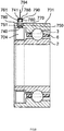
- FIG. 1 is a schematic sectional view of a ball bearing device that is a rolling bearing device according to a first embodiment of the invention, the sectional view being taken along the axial direction of the ball bearing device.
- the ball bearing device includes an outer ring 1, which may function as a first bearing ring, an inner ring 2, which may function as a second bearing ring, a plurality of balls 3, which may function as a plurality of rolling elements, and a lubricant supply unit 4.
- the outer ring 1 may function as one member out of the first bearing ring and the second bearing ring.
- the outer ring 1 is fixed to a housing 10, which is as an example of a fixed member (a member to which the outer ring 1 is fixed).
- the housing 10 has a large-diameter cylindrical inner periphery portion 35 and a small-diameter cylindrical inner periphery portion 36.
- the inner diameter of the large-diameter cylindrical inner periphery portion 35 is larger than the inner diameter of the small-diameter cylindrical inner periphery portion 36.
- the housing 10 has a step portion 30 that extends radially inward from the large-diameter cylindrical inner periphery portion 35.
- the large-diameter cylindrical inner periphery portion 35 is connected to the small-diameter cylindrical inner periphery portion 36 via the step portion 30. As illustrated in FIG.
- the outer peripheral face of the outer ring 1 is fixed to the large-diameter cylindrical inner periphery portion 35.
- One axial side end face 16 of the outer ring 1 is in contact with the step portion 30. In this way, the outer ring 1 is fixed to the housing 10.
- the axial end face of the step portion 30 constitutes the axial end face of the fixed member.
- the one axial side end face 16 of the outer ring 1 constitutes a positioning face of the one member.
- the outer ring 1 has, in its inner periphery, an angular raceway groove 11, which may function as an inner periphery raceway surface.
- the height of one shoulder portion, which is located on one axial side of the raceway groove 11, is greater than the height of the other shoulder portion, which is located on the other axial side of the raceway groove 11.
- the outer ring 1 has a unit fixation recessed portion 13.
- the unit fixation recessed portion 13 is located on the opposite side of the one shoulder portion from the raceway groove 11 in the axial direction.
- the unit fixation recessed portion 13 is opened inward in the radial direction and also opened toward the one side in the axial direction.
- the inner ring 2 is fixedly fitted onto a rotary shaft (not illustrated).
- the inner ring 2 has, in its outer periphery, a raceway groove 21, which may function as an outer periphery raceway surface, and a recessed portion 23.
- the recessed portion 23 is located on one axial side of the raceway groove 21 so as to be apart from the raceway groove 21 in the axial direction.
- the recessed portion 23 is opened outward in the radial direction and also opened toward the one side in the axial direction.
- the recessed portion 23 overlaps with the unit fixation recessed portion 13 in the radial direction.
- the balls 3 are held between the raceway groove 11 of the outer ring 1 and the raceway groove 21 of the inner ring 2 by a cage 6, and arranged at intervals in the circumferential direction.
- the lubricant supply unit 4 has a generally rectangular shape in the sectional view illustrated in FIG. 1 .
- the lubricant supply unit 4 has an annular shape.
- the lubricant supply unit 4 has a cylindrical outer peripheral face 40, and the cylindrical outer peripheral face 40 is fixedly fitted to the cylindrical inner peripheral face of the unit fixation recessed portion 13.
- the cylindrical inner peripheral face of the unit fixation recessed portion 13 has, at a given position in the axial direction, an engagement recessed portion having a prescribed depth in the radial direction.
- the cylindrical outer peripheral face 40 of the lubricant supply unit 4 has, at a given position in the axial direction, an engagement projected portion having a prescribed height in the radial direction.
- the depth of the engagement recessed portion in the radial direction is substantially equal to the height of the engagement projected portion in the radial direction.
- an engagement projected portion may be formed on the cylindrical inner peripheral face of the unit fixation recessed portion 13 and an engagement recessed portion may be formed in the cylindrical outer peripheral face of the lubricant supply unit 4 and the engagement projected portion of the unit fixation recessed portion 13 may be engaged with the engagement recessed portion of the lubricant supply unit 4.
- the lubricant supply unit 4 is provided with a first radially separated electrode 50 and a second radially separated electrode 51.
- Each of the first radially separated electrode 50 and the second radially separated electrode 51 is fixed to one axial side end face 53 of the lubricant supply unit 4 so as to protrude in the axial direction from the one axial side end face 53.
- the first radially separated electrode 50 is located apart from the second radially separated electrode 51 in the radial direction of the outer ring 1.
- the first radially separated electrode 50 is an anode
- the second radially separated electrode 51 is a cathode.
- the first radially separated electrode 50 and the second radially separated electrode 51 are provided to supply electric power to a micropump 71 (described later) from an external power source.
- reference numerals 60, 61 denote external electrodes on the power source side, which are fixed to the housing 10 so as to be immovable relative to the housing 10.
- the first external electrode 60 is in contact with the first radially separated electrode 50 and the second external electrode 61 is in contact with the second radially separated electrode 51.
- Each of the first and second external electrodes 60, 61 has an annular shape.
- FIG. 2 is an enlarged schematic sectional view illustrating part of the ball bearing device in FIG. 1 , the part being part of the lubricant supply unit 4 illustrated in a lower half part of FIG. 1 .
- the lubricant supply unit 4 includes a tank 70 and the micropump 71 having a driven portion.
- the tank 70 is formed of a hollow annular member that stores lubricating oil. Note that the tank 70 may be a non-annular member that is installed in a prescribed angular range in the circumference direction.
- the micropump 71 is a diaphragm pump.
- the micropump 71 includes a piezoelectric element 72, a diaphragm 73, which serves as the driven portion, and a discharge nozzle 78.
- the discharge nozzle 78 is directed to a position near one end of the raceway groove 21 of the inner ring 2 and the balls 3.
- the electric power from the external power source is supplied to the piezoelectric element 72 through the first radially separated electrode 50 and the second radially separated electrode 51 to drive the piezoelectric element 72.
- the diaphragm 73 is pulled and pushed by the piezoelectric element 72 to suck in the lubricating oil from the tank 70 into a pump chamber 75 and discharge the sucked lubricating oil from the discharge nozzle 78.
- the lubricating oil from the tank 70 is supplied to the position near the raceway groove 21 of the inner ring 2 and the balls 3, by a minute amount each time.
- dashed lines 80 extending in the up-down direction in FIG. 1 indicate that the tank 70 has an annular shape (this applies also to the following embodiments).
- a dashed line 81 extending in the lateral direction in FIG. 1 indicates a region of a phase in the circumferential direction, where the micropump 71 is present (this applies also to the following embodiments).
- a base oil of the lubricating oil any one of an ester oil, an ether oil, a fluorinated oil, a silicone oil, and a synthetic hydrocarbon oil may be used.
- the lubricating oil examples include a fluorinated polymer oil, a fluorinated polyether oil, an alkyl diphenyl ether oil, a polyphenyl ether oil, a polyol ester oil, and a polyalpha olefin oil.
- a fluorinated polymer oil examples include a fluorinated polymer oil, a fluorinated polyether oil, an alkyl diphenyl ether oil, a polyphenyl ether oil, a polyol ester oil, and a polyalpha olefin oil.
- one of these oils may be used by itself or a mixture of two or more of these oils may be used.
- grease may be used instead of the lubricating oil.
- a miniature motor or the like may be used instead of the piezoelectric element 72.
- the micropump 71 has, on its side face, a lubricant suction nozzle 85.
- the nozzle 85 is fixedly fitted in a lubricant supply hole 86, which is formed in a side face of the tank 70, with a rubber tube 82 interposed between the nozzle 85 and the wall face of the lubricant supply hole 86.
- the tank 70 and the micropump 71 are coupled to each other with the tank 70 and the micropump 71 communicated with each other.
- FIG. 2 the illustration of a wire for the micropump 71 and the first and second radially separated electrodes 50, 51 (see FIG. 1 ) is omitted.
- the wire for the micropump 71 is disposed so as to hardly appear outside the lubricant supply unit 4.
- the first and second radially separated electrodes 50, 51 for the micropump 71 are fixed to an end face of the tank 70 of the lubricant supply unit 4 so as to be immovable relative to the tank 70.
- the first and second radially separated electrodes 50, 51 to which electric power for driving the micropump 71 is supplied, are fixed to the tank 70 that is stationary relative to the micropump 71, in a state where the first and second radially separated electrodes 50, 51 are exposed on the outside of the tank 70 of the lubricant supply unit 4.
- the electrodes 50, 51 are exposed on the outside of the tank 70 of the lubricant supply unit 4 and the wire hardly appears outside the lubricant supply unit 4.
- the first embodiment it is possible to supply the electric power for operating the micropump 71 from the external power source. As a result, it is possible to improve the reliability of electric power supply, and an increase in the size of the ball bearing device due to an increase in the battery capacity is no longer necessary.
- the radially separated electrodes 50, 51 are fixed to the axial end face of the tank 70.
- the outer ring 1 to which the lubricant supply unit 4 is fixed has the end face 16, which serves as the positioning face that comes into contact with the housing 10 in the axial direction.
- the end face 16 is located at a position apart from the first and second radially separated electrodes 50, 51.
- the one member is the outer ring 1, and the first and second radially separated electrodes 50, 51 for the micropump 71 are connected to the first and second external electrodes 60, 61 disposed on the housing 10 to which the outer ring 1 is fixed, respectively.
- the one member may be the inner ring, and electrodes for the pump may be connected to external electrodes disposed on the shaft member to which the inner ring is fixed.
- each of the first and second external electrodes 60, 61 has an annular shape, whereas each of the first and second radially separated electrodes 50, 51 for the micropump 71 has a non-annular shape.
- each external electrode may have a non-annular shape, whereas each electrode for the pump may have an annular shape. In this way, the electrodes may be configured such that electrical connection is maintained even if the electrodes for the pump move in the circumferential direction relative to the external electrodes.
- each of the first and second external electrodes 60, 61 has an annular shape, whereas each of the first and second radially separated electrodes 50, 51 for the micropump 71 has a non-annular shape.
- both the external electrodes and the electrodes for the pump may have a non-annular shape. This is because, if positioning of the one member is carried out such that the one member is immovable relative to the fixed member and positioning of the pump is carried out such that the pump is immovable relative to the one member, it is possible to reliably maintain the electrical connection even if both the external electrodes and the electrodes for the pump have a non-annular shape.
- the lubricant supply unit 4 is fixed to the outer ring 1 by engaging the engagement recessed portion and the engagement projected portion with each other.
- the lubricant supply unit 4 may be fixed to the one member with an adhesive, or the lubricant supply unit 4 may be fixed to the one member by press-fitting.
- the lubricant supply unit 4 may be fixed to the one member in such a manner that the lubricant supply unit 4 is held between a step portion and a snap ring in the axial direction, so that the lubricant supply unit 4 is immovable relative to the one member in the axial direction.
- the lubricant supply unit 4 may be fixed to the one member with the use of a fastening member.
- the lubricant supply unit 4 may be fixed to the one member in any known method.
- the lubricant supply unit 4 has the two electrodes 50, 51.
- the lubricant supply unit 4 may have only one electrode, and only one external electrode corresponding to the one electrode may be provided.
- the lubricant supply unit 4 may have three or more electrodes, and external electrodes the number of which corresponds to the number of the electrodes may be provided.
- the first and second radially separated electrodes 50, 51 for the micropump 71 are fixed to the tank 70 of the lubricant supply unit 4 so as to be immovable relative to the tank 70, which may function as a stationary member.
- at least one electrode for the micropump 71 may be provided with an urging member that urges the electrode in one direction and fixed to the one member or the tank 70 of the lubricant supply unit 4, in a state where the position of the one electrode relative to the one member or the tank 70 of the lubricant supply unit 4, which is stationary relative to the micropump 71, is variable. Electrical connection may be reliably established by pressing the at least one electrode to the corresponding external electrode in the one direction.
- This configuration may be achieved by fixing one end portion of a metal spring (formed of a coil spring, a helical spring, or the like) to the axial end face of the one member or the tank 70 electrically connecting the one end portion to the wire for the pump, and fixing the other end portion of the metal spring to the electrode that is guided by a cylindrical guide portion or the like and prevented from moving in directions other than the one direction.
- a metal spring formed of a coil spring, a helical spring, or the like
- the lubricant supply unit 4 includes the micropump 71.
- the lubricant supply unit 4 may include a common pump of which the size and other features are not restricted, instead of the micropump 71.
- the first and second external electrodes 60, 61 are fixed to the housing 10.
- the external electrodes may be fixed to a member that is fixed to the housing.
- the external electrodes may be fixed to, for example, a spacer.
- a main body of the lubricant supply unit 4 is disposed between the outer ring 1 and the inner ring 2 in the radial direction.
- part of or the entirety of the lubricant supply unit may be disposed in a space other than the space between the first bearing ring and the second bearing ring in the radial direction. This configuration may be achieved by fixing a part of the lubricant supply unit to an axial end face of the first bearing ring with an adhesive or the like.
- the micropump 71 and the tank 70 which are parts of the main body of the lubricant supply unit 4, may be removable from each other.
- the nozzle 78 of the micropump 71 is directed to the raceway groove 21 of the inner ring 2 and the balls 3.
- the nozzle of the pump may be directed to at least one of the raceway surface of the inner ring and each rolling element and the raceway surface of the outer ring.
- the ball bearing device does not include a seal member that seals the space between the outer ring 1 and the inner ring 2.
- a seal member that seals at least one axial side of the space between the first bearing ring and the second bearing ring may be provided.
- the raceway groove of the outer ring 1 is the angular raceway groove 11
- the raceway groove of the inner ring 2 is the raceway groove 21 that is not an angular raceway groove.
- both the first bearing ring and the second bearing ring may have angular raceway grooves
- one of the first bearing ring and the second bearing ring may have an angular raceway groove
- neither the first bearing ring nor the second bearing ring may have an angular raceway groove.
- one member out of the first bearing ring and the second bearing ring is the outer ring 1, and the other member out of the first bearing ring and the second bearing ring is the inner ring 2.
- one member out of the first bearing ring and the second bearing ring may be the outer ring or the inner ring, and the other member out of the first bearing ring and the second bearing ring may be an intermediate ring.
- one member out of the first bearing ring and the second bearing ring may be an intermediate ring, and the other member out of the first bearing ring and the second bearing ring may be the outer ring or the inner ring.
- the rolling elements are the balls 3.
- the rolling elements may be cylindrical rollers, tapered rollers, convex rollers (spherical rollers), or needle rollers.
- two or more kinds of rolling elements selected from balls, cylindrical rollers, tapered rollers, and convex rollers (spherical rollers) may be arranged in respective rows of which the number corresponds to the number of types of the rolling elements.
- FIG. 3 is a schematic sectional view of a ball bearing device that is a rolling bearing device according to a second embodiment of the invention, the sectional view being taken along the axial direction of the ball bearing device.
- the same configurations as those in the first embodiment will be denoted by the same reference numerals as those in the first embodiment, and detailed description thereof will be omitted. Further, in the second embodiment, description of the same advantageous effects and modified examples as those in the first embodiment will be omitted.
- a micropump of a lubricant supply unit 104 is provided with a first circumferentially separated electrode 150 and a second circumferentially separated electrode 151.
- the first circumferentially separated electrode 150 is located so as to be apart from the second circumferentially separated electrode 151 in the circumferential direction of the outer ring 1, which may function as one member.
- the first circumferentially separated electrode 150 is apart from the second circumferentially separated electrode 151 in the circumferential direction. As a result, it is possible to reliably prevent the first circumferentially separated electrode 150 and the second circumferentially separated electrode 151 from being electrically connected to each other, and securely connect the first circumferentially separated electrode 150 and the second circumferentially separated electrode 151 to external electrodes.
- FIG. 4 is a schematic sectional view of a ball bearing device that is a rolling bearing device according to a third embodiment of the invention, the sectional view being taken along the axial direction of the ball bearing device.
- the same configurations as those in the first embodiment will be denoted by the same reference numerals as those in the first embodiment, and detailed description thereof will be omitted. Further, in the third embodiment, description of the same advantageous effects and modified examples as those in the first embodiment will be omitted.
- the third embodiment differs from the first embodiment in the following respect. Electrodes 250, 251 for a micropump of a lubricant supply unit 204 are fixed to an outer ring 201, which may function as one member in the third embodiment, whereas the first and second radially separated electrodes 50, 51 for the micropump 71 are fixed to the tank 70 of the lubricant supply unit 4.
- the lubricant supply unit 204 is fixed to the inner peripheral face of the outer ring 201 by fixing means such as an adhesive.
- the micropump of the lubricant supply unit 204 has the first radially separated electrode 250 and the second radially separated electrode 251.
- the first radially separated electrode 250 is located at the same phase (position) in the circumferential direction as the second radially separated electrode 251.
- the first radially separated electrode 250 is apart from the second radially separated electrode 251 in the radial direction.
- Each of the first radially separated electrode 250 and the second radially separated electrode 251 protrudes in the axial direction from one axial side end face of the outer ring 201.
- Each of the first radially separated electrode 250 and the second radially separated electrode 251 is fixed to the outer ring 201, in a state where the first and second radially separated electrodes 250, 251 are exposed on the outside of the outer ring 201.
- Two wires for the micropump of the lubricant supply unit 204 extend to the one axial side end face of the outer ring 201 through a passage (not illustrated) formed in the outer ring 201.
- One wire is electrically connected to the first radially separated electrode 250, and the other wire is electrically connected to the second radially separated electrode 251.
- a housing 210 has an annular step portion 230, and an annular first external electrode 260 and an annular second external electrode 261 are disposed on the axial end face of the step portion 230 so as to protrude in the axial direction from the axial end face.
- the position of the first external electrode 260 in the axial direction coincides with the position of the second external electrode 261 in the axial direction, and the position of the first external electrode 260 in the circumferential direction also coincides with the position of the second external electrode 261 in the circumferential direction.
- the first external electrode 260 is apart from the second external electrode 261 in the radial direction.
- a reference numeral 278 denotes a nozzle of the micropump.
- the first and second radially separated electrodes 250, 251 are fixed to the outer ring 201, which may function as one member that is fixed to the housing 210, which may function as a fixed member.
- FIG. 5 is a schematic sectional view of a ball bearing device that is a rolling bearing device according to a fourth embodiment of the invention, the sectional view being taken along the axial direction of the ball bearing device.
- the same configurations as those in the first embodiment will be denoted by the same reference numerals as those in the first embodiment, and detailed description thereof will be omitted. Further, in the fourth embodiment, description of the same advantageous effects and modified examples as those in the first embodiment will be omitted.
- a lubricant supply unit 304 has a first circumferentially separated electrode 350 and a second circumferentially separated electrode 351.
- the feature of the fourth embodiment that the first and second circumferentially separated electrodes 350, 351 are fixed to an outer ring 301, which may function as one member fixed to a housing which may function as a fixed member, is the same as the above-described feature of the third embodiment.
- the fourth embodiment differs from the third embodiment in that the two electrodes 350, 351 are not separated not in the radial direction but in the circumferential direction.
- the fourth embodiment as well as in the third embodiment, it is possible to set the positions, at which the first and second circumferentially separated electrodes 350, 351 are present, closer to the housing. As a result, it is possible to electrically connect the first and second circumferentially separated electrodes 350, 351 to the external electrodes more easily and reliably.
- FIG. 6 is a schematic sectional view of a ball bearing device that is a rolling bearing device according to a fifth embodiment of the invention, the sectional view being taken along the axial direction of the ball bearing device.
- the same configurations as those in the first embodiment will be denoted by the same reference numerals as those in the first embodiment, and detailed description thereof will be omitted.
- description of the same advantageous effects and modified examples as those in the first embodiment will be omitted.
- description of the same advantageous effects as those in the second to fourth embodiments will be omitted.
- a lubricant supply unit 404 has a rod-like electrode formed portion 415 that protrudes in the axial direction.
- the lubricant supply unit 404 has a first axially separated electrode 450 and a second axially separated electrode 451.
- Each of the first axially separated electrode 450 and the second axially separated electrode 451 is fixed to the electrode formed portion 415.
- the first axially separated electrode 450 is apart from the second axially separated electrode 451 in the axial direction.
- each of the first axially separated electrode 450 and the second axially separated electrode 451 protrudes radially outward from the electrode formed portion 415.
- a housing 410 has an annular protrusion 423 used for positioning.
- the protrusion 423 has a generally rectangular shape in a cross section taken along the axial direction.
- first and second external electrodes 460, 461 that protrude inward in the radial direction are fixed to the inner peripheral face of the housing 410.
- the first external electrode 460 is apart from the second external electrode 461 in the axial direction.
- the first axially separated electrode 450 is electrically connected to the first external electrode 460
- the second axially separated electrode 451 is electrically connected to the second external electrode 461.
- the two electrodes 450, 451 are apart from each other in the axial direction.
- FIG. 7 is a schematic sectional view of a ball bearing device that is a rolling bearing device according to a sixth embodiment of the invention, the sectional view being taken along the axial direction of the ball bearing device.
- the same configurations as those in the first embodiment will be denoted by the same reference numerals as those in the first embodiment, and detailed description thereof will be omitted.
- description of the same advantageous effects and modified examples as those in the first embodiment will be omitted.
- description of the same advantageous effects as those in the second to fifth embodiments will be omitted.
- the sixth embodiment differs from the other embodiments in that each of two electrodes 550, 551 for a micropump of a lubricant supply unit 504 is exposed on the radially outside of the outer peripheral face of an outer ring 501, which may function as one member.
- the lubricant supply unit 504 is fixed to the inner peripheral face of the outer ring 501.
- the outer ring 501 has a first through-hole 580 and a second through-hole 581 at the same phase in the circumferential direction.
- the first through-hole 580 and the second through-hole 581 are extended in the radial direction to pass through the outer ring 501.
- the first through-hole 580 is apart from the second through-hole 581 in the axial direction.
- each of the first through-hole 580 and the second through-hole 581 has a recessed portion, which is able to accommodate the entirety of an electrode, at its radially outer end portion.
- the recessed portion of the first through-hole 580 is able to accommodate the first axially separated electrode 550
- the recessed portion of the second through-hole 581 is able to accommodate the second axially separated electrode 551. All the portion of the first through-hole 580 other than the recessed portion overlaps with the first axially separated electrode 550 in the radial direction. All the portion of the second through-hole 581 other than the recessed portion overlaps with the second axially separated electrode 551 in the radial direction.
- the first axially separated electrode 550 is electrically connected to one of electrodes for the micropump by a wire extending through the first through-hole 580.
- the second axially separated electrode 551 is electrically connected to the other one of the electrodes for the micropump by a wire extending through the second through-hole 581.
- the ball bearing device in the sixth embodiment has two urging members (each of which is formed of a coil spring or the like).
- One urging member out of the two urging members extends through the first through-hole 580.
- the other urging member extends through the second through-hole 581.
- One end portion of the one urging member is in contact with the radially outer face of the lubricant supply unit 504.
- the other end portion of the one urging member is in contact with the radially inner end face bottom face) of the first axially separated electrode 550.
- the one urging member urges the first axially separated electrode 550 in the radially outward direction, which is an example of one direction.
- the first axially separated electrode 550 is pushed radially inward by, for example, the inner peripheral face of the housing so as to be located within the recessed portion of the first through-hole 580, during axial movement of the first axially separated electrode 550 relative to the inner peripheral face of the housing.
- each of one axial side end face 590 and the other axial side end face 591 of the first axially separated electrode 550 is sloped toward the center of the first axially separated electrode 550 such that the distance between the axial end faces 590, 591 is reduced in a direction toward the radially outer side. That is, each of the axial end faces 590, 591 of the first axially separated electrode 550 is a sloped face that is tapered toward the radially outer side.
- the first axially separated electrode 550 falls into the recessed portion by a radially inward force that one of the sloped faces 590, 591 receives from the housing when the housing is moved in the axial direction relative to the outer ring 501.
- the first axially separated electrode 550 is pushed toward a first external electrode (not illustrated), which is disposed on the inner peripheral side of the housing, radially outward by the urging member. In this way, the first axially separated electrode 550 is electrically connected to the first external electrode reliably.
- the second axially separated electrode 551 is electrically connected to a second external electrode, which is disposed on the inner peripheral side of the housing, by the same structure as that of the first axially separated electrode 550.
- electric power is supplied to the micropump of the lubricant supply unit 504 from an external power source.
- the urging members are disposed in the first through-hole 580 and the second through-hole 581 in the sixth embodiment.
- FIG. 8 is a schematic sectional view of a ball bearing device that is a rolling bearing device according to a seventh embodiment of the invention, the sectional view being taken along the axial direction of the ball bearing device.
- the same configurations as those in the first embodiment will be denoted by the same reference numerals as those in the first embodiment, and detailed description thereof will be omitted.
- description of the same advantageous effects and modified examples as those in the first embodiment will be omitted.
- description of the same advantageous effects as those in the second to sixth embodiments will be omitted.
- a reference numeral 601 denotes an outer ring that may function as one member
- a reference numeral 604 denotes a lubricant supply unit.
- the seventh embodiment differs from the sixth embodiment in that a first circumferentially separated electrode 650 and a second circumferentially separated electrode 651 are apart from each other not in the axial direction but in the circumferential direction.
- the seventh embodiment is the same as the sixth embodiment in the following respects.
- the first circumferentially separated electrode 650 is electrically connected to a first external electrode (not illustrated) disposed on the inner peripheral side of a housing with the use of a first through-hole 680 and an urging member (not illustrated)
- the second circumferentially separated electrode 651 is electrically connected to a second external electrode (not illustrated) disposed on the inner peripheral side of the housing with the use of a second through-hole 681 and an urging member (not illustrated).
- the seventh embodiment is the same as the sixth embodiment in the following respects.
- the axial end faces of each of the circumferentially separated electrodes 650, 651 are formed as sloped faces.
- FIG. 9 is a schematic sectional view of a ball bearing device that is an aspect according to the background of the invention ("background aspect"), the sectional view being taken along the axial direction of the ball bearing device.
- background aspect the same configurations as those in the first embodiment will be denoted by the same reference numerals as those in the first embodiment, and detailed description thereof will be omitted.
- description of the same advantageous effects and modified examples as those in the first embodiment will be omitted.
- description of the same advantageous effects as those in the second to seventh embodiments will be omitted.
- the background aspect differs from the other embodiments in that electric power is supplied from an external power source to first and second axially separated electrodes 750, 751 for a micropump of a lubricant supply unit 704 of the ball bearing device with the use of a connector (socket) 790.
- the radially outer face of the lubricant supply unit 704 is fixed to an outer ring 701, which may function as one member.
- an outer ring 701 which may function as one member.
- Part of the outer face of the lubricant supply unit 704 is exposed to the outside.
- an electrode structural body 740 is fixed to part of the outer face of the lubricant supply unit 704.
- the electrode structural body 740 includes the first axially separated electrode 750, the second axially separated electrode 751, and an insulating portion 770.
- the first axially separated electrode 750 and the second axially separated electrode 751 are disposed such that the insulating portion 770 is interposed therebetween in the axial direction.
- the first axially separated electrode 750 is apart from the second axially separated electrode 751 in the axial direction.
- the height of the first axially separated electrode 750 coincides with the height of the second axially separated electrode 751.
- the connector 790 has a recessed portion 741 having a rectangular cross section.
- the depth of the recessed portion 741 is substantially equal to the length obtained by subtracting the height of the first axially separated electrode 750 from the height of the insulating portion 770.
- the shape of the recessed portion 741 conforms to the shape of a portion of the insulating portion 770, which protrudes from the first and second axially separated electrodes 750, 751.
- the connector 790 includes a first external electrode 760 and a second external electrode 761.
- the first external electrode 760 and the second external electrode 761 face each other with the recessed portion 741 interposed therebetween.
- the connector 790 has an insulating portion 788, and the insulating portion 788 overlaps with the recessed portion 741 in the depth direction of the recessed portion 741.
- the first external electrode 760 and the second external electrode 761 are reliably prevented from being electrically connected to each other by the insulating portion 788.
- the recessed portion of the connector 790 is fitted onto the portion of the insulating portion 770, which protrudes from the first and second axially separated electrodes 750, 751, so that the first axially separated electrode 750 is electrically connected to the first external electrode 760 and the second axially separated electrode 751 is electrically connected to the first external electrode 761.
- a reference numeral 794 denotes a cable of the connector 790. Two wires are disposed in the cable 794 so as not to be electrically connected to each other.
- a housing (not illustrated) to which an outer ring 701, which may function as one member, has a through-hole. The through-hole overlaps with the electrode structural body 740 in the radial direction of the outer ring 701 in a state where the outer ring 701 is fixed to a prescribed position of the housing. In this way, the connector 790 is connected to the electrode structural body 740 from the outside via the through-hole of the housing. Note that, it is needless to say that, if the through-hole 780 of the outer ring 701 is formed so as not to overlap with the housing in the radial direction, it is no longer necessary to form a through-hole in the housing.
- the two electrodes may be disposed such that none of their axial directions, radial directions, and circumferential directions coincide with each other, the two electrodes may be disposed such that only one kind of directions among their axial directions, radial directions and the circumferential directions coincide with each other, or the two electrodes may be disposed such that only two kinds of directions among their axial directions, radial directions and the circumferential directions coincide with each other.
- the rolling bearing according to the invention has anodes and cathodes for supplying electric power to the pump, there may be two or more electrodes that serve as the anodes, and the two or more electrodes may be connected to each other by a wire.
- the rolling bearing according to the invention has anodes and cathodes for supplying electric power to the pump, there may be two or more electrodes that serve as the cathodes, and the two or more electrodes may be connected to each other through a wire.
- the degree of flexibility of electrical connection with an external power source may be increased.
- rolling bearing device may be mounted in any machines such as an industrial machine and a construction machine. Further, it is needless to say that two or more configurations described in the first to seventh embodiments and all the modified examples and background aspects may be combined with each other.
Landscapes
- Engineering & Computer Science (AREA)
- General Engineering & Computer Science (AREA)
- Mechanical Engineering (AREA)
- Rolling Contact Bearings (AREA)
Claims (7)
- Wälzlageranordnung mit einer Wälzlagervorrichtung und einem fixierten Element (10), wobei die Wälzlagervorrichtung:einen ersten Lagerring (1) mit einer Innenumfangslaufflächenoberfläche (11);einen zweiten Lagerring (2) mit einer Außenumfangslaufflächenoberfläche (21);eine Vielzahl von Wälzelementen (3), die zwischen der Innenumfangslaufflächenoberfläche (11) des ersten Lagerrings (1) und der Außenumfangslaufflächenoberfläche (21) des zweiten Lagerrings (2) angeordnet sind; undeine Schmiermittelzufuhreinheit (4) mit zumindest einem Tank (70) und einer Pumpe (71) aufweist, die Schmiermittel zu der Innenumfangslaufflächenoberfläche (11) des ersten Lagerrings (1) und/oder der Außenumfangslaufflächenoberfläche (21) des zweiten Lagerrings (2) und/oder den Wälzelementen (3) zuführt, wobeidie Schmiermittelzufuhreinheit (4) eine oder mehrere Elektroden (50, 51) hat, zu denen elektrische Energie von einer externen Energiequelle zugeführt ist, und ein Teil der Schmiermittelzufuhreinheit (4) an einem Element (1) aus dem ersten Lagerring und dem zweiten Lagerring fixiert ist, undjede der einen oder mehreren Elektroden (50, 51) an dem einen Element (1) oder dem Tank (70) der Schmiermittelzufuhreinheit (4) fixiert ist, wobei der Tank (70) relativ zur Pumpe (71) stationär ist, in einem Zustand, in dem jede der einen oder mehreren Elektroden (50, 51) an einer Außenseite des einen Elements (1) oder des Tanks der Schmiermittelzufuhreinheit (4) freiliegt,
dadurch gekennzeichnet, dass in der Wälzlageranordnungdas eine Element (1) eine Positionierfläche (16) aufweist, die mit einer Axialendfläche des fixierten Elements (10), an welchem das eine Element (1) fixiert ist, in Kontakt gebracht ist, unddie eine oder mehreren Elektroden (50, 51) mit einer oder mehreren entsprechenden externen Elektroden (60, 61) in Kontakt gebracht sind, die am fixierten Element (10) so fixiert sind, dass sie relativ zum fixierten Element (10) unbewegbar sind. - Wälzlageranordnung nach Anspruch 1, wobei jede der einen oder mehreren Elektroden (50, 51) an einer Umfangsfläche des Tanks (70), einer Endfläche des Tanks (70), einer Umfangsfläche des einen Elements (1) oder einer Endfläche des einen Elements (1) fixiert ist.
- Wälzlageranordnung nach Anspruch 1 oder 2, wobei die Elektroden (250, 251), die an dem einen Element (201) fixiert sind, an der Positionierfläche an voneinander beabstandeten Positionen fixiert sind.
- Wälzlageranordnung nach einem der Ansprüche 1 bis 3, ferner mit einem Drängelement, das zumindest eine der Elektroden (550, 551) in einer Richtung drängt,
wobei die zumindest eine der Elektroden (550, 551) an dem einen Element (501) oder dem Tank (70) in einem Zustand fixiert ist, in dem eine Position der zumindest einen der Elektroden (550, 551) relativ zu dem einen Element (501) oder dem Tank (70) variabel ist. - Wälzlageranordnung nach einem der Ansprüche 1 bis 4, wobei
die Elektroden (550, 551) eine erste axial getrennte Elektrode (550) und eine zweite axial getrennte Elektrode (551) aufweisen; und
die erste axial getrennte Elektrode (550) in einer Axialrichtung des einen Elements (501) von der zweiten axial getrennten Elektrode (551) beabstandet ist. - Wälzlageranordnung nach einem der Ansprüche 1 bis 5, wobei:die Elektroden (150, 151) eine erste umfangsweise getrennte Elektrode (150) und eine zweite umfangsweise getrennte Elektrode (151) aufweisen; unddie erste umfangsweise getrennte Elektrode (150) in einer Umfangsrichtung des einen Elements (1) von der zweiten umfangsweise getrennten Elektrode (151) beabstandet ist.
- Wälzlageranordnung nach einem der Ansprüche 1 bis 6, wobei:die Elektroden (50, 51) eine erste radial getrennte Elektrode (50) und eine zweite radial getrennte Elektrode (51) aufweisen; unddie erste radial getrennte Elektrode (50) in einer Radialrichtung des einen Elements (1) von der zweiten radial getrennten Elektrode (51) beabstandet ist.
Applications Claiming Priority (1)
| Application Number | Priority Date | Filing Date | Title |
|---|---|---|---|
| JP2013040824A JP6160125B2 (ja) | 2013-03-01 | 2013-03-01 | 転がり軸受装置 |
Publications (3)
| Publication Number | Publication Date |
|---|---|
| EP2787230A2 EP2787230A2 (de) | 2014-10-08 |
| EP2787230A3 EP2787230A3 (de) | 2015-07-15 |
| EP2787230B1 true EP2787230B1 (de) | 2018-08-29 |
Family
ID=50238124
Family Applications (1)
| Application Number | Title | Priority Date | Filing Date |
|---|---|---|---|
| EP14156806.3A Not-in-force EP2787230B1 (de) | 2013-03-01 | 2014-02-26 | Wälzlagervorrichtung |
Country Status (4)
| Country | Link |
|---|---|
| US (2) | US9228611B2 (de) |
| EP (1) | EP2787230B1 (de) |
| JP (1) | JP6160125B2 (de) |
| CN (2) | CN104019136B (de) |
Families Citing this family (15)
| Publication number | Priority date | Publication date | Assignee | Title |
|---|---|---|---|---|
| KR20140060318A (ko) * | 2011-09-13 | 2014-05-19 | 엔티엔 가부시키가이샤 | 베어링 장치 |
| JP6446887B2 (ja) * | 2014-07-23 | 2019-01-09 | 株式会社ジェイテクト | 転がり軸受装置及び給油ユニット |
| JP6599626B2 (ja) * | 2015-03-23 | 2019-10-30 | Ntn株式会社 | 軸受装置および機械装置 |
| JP2017002942A (ja) * | 2015-06-05 | 2017-01-05 | 株式会社ジェイテクト | 転がり軸受装置 |
| JP6648432B2 (ja) * | 2015-07-14 | 2020-02-14 | 株式会社ジェイテクト | 軸受装置及び給油ユニット |
| US9958005B2 (en) * | 2015-10-13 | 2018-05-01 | Shimadzu Corporation | Oil-lubricated bearing device and vacuum pump |
| JP6746917B2 (ja) * | 2016-01-12 | 2020-08-26 | 株式会社ジェイテクト | 転がり軸受装置 |
| JP6686473B2 (ja) * | 2016-01-29 | 2020-04-22 | 株式会社ジェイテクト | 軸受装置および軸受への潤滑油の供給方法 |
| DE102017125950A1 (de) * | 2016-11-11 | 2018-05-17 | Jtekt Corporation | Wälzlagervorrichtung |
| CN107084198B (zh) * | 2017-06-06 | 2022-10-18 | 湖南美蓓达科技股份有限公司 | 一种便于加润滑油的轴承 |
| TWI663030B (zh) * | 2018-08-08 | 2019-06-21 | 益航電子股份有限公司 | 傳動軸及周邊結構 |
| CA3057920A1 (en) | 2019-01-15 | 2020-07-15 | Rolls-Royce Corporation | Bearing for use in high speed application |
| CN110206993B (zh) * | 2019-05-28 | 2021-01-05 | 哈尔滨工业大学 | 一种基于无阀压电微泵的轴承主动微冗余润滑机构 |
| WO2021036657A1 (zh) * | 2019-08-30 | 2021-03-04 | 张志刚 | 自激式油雾喷射润滑高速轴承、润滑方法及应用 |
| CN114838058B (zh) * | 2022-05-25 | 2024-07-16 | 天津钕领节能科技有限公司 | 一种电机轴承状态监控预警装置及轴承用散热润滑装置 |
Family Cites Families (39)
| Publication number | Priority date | Publication date | Assignee | Title |
|---|---|---|---|---|
| US3206261A (en) * | 1962-04-04 | 1965-09-14 | Franklin Electric Co Inc | Grease feed device |
| US3581267A (en) * | 1968-08-14 | 1971-05-25 | Electric Conductor Bearings In | Electric conductor bearings |
| JPS61139700A (ja) * | 1984-12-10 | 1986-06-26 | Toshiba Corp | X線管用ベアリングボ−ルの製造方法 |
| US4738336A (en) * | 1987-04-27 | 1988-04-19 | Honeywell, Inc. | Controlled replenishing lubrication system |
| US4858427A (en) * | 1988-08-08 | 1989-08-22 | General Motors Corporation | Secondary oil system for gas turbine engine |
| US5423399A (en) * | 1993-01-21 | 1995-06-13 | Honeywell Inc. | Gas pressurized oil replenishment system for bearing assemblies |
| JPH07217662A (ja) * | 1994-02-01 | 1995-08-15 | Nippon Seiko Kk | 固体潤滑転がり軸受 |
| US5775920A (en) * | 1995-09-01 | 1998-07-07 | Methode Electronics, Inc. | Rolling elastomer contact clockspring |
| CA2193011C (en) * | 1996-12-16 | 2002-03-26 | Robert Henry Rehder | Anti-friction rotating contact assembly |
| US5851120A (en) * | 1997-02-27 | 1998-12-22 | Raytheon Company | Rotary conduit/ball connector |
| JPH1167402A (ja) * | 1997-08-08 | 1999-03-09 | Harness Sogo Gijutsu Kenkyusho:Kk | 吸音材および該吸音材を備えたケーブルリール |
| GB2350487B (en) * | 1999-05-25 | 2002-12-24 | Transense Technologies Plc | Electrical signal coupling device |
| US6299454B1 (en) * | 2000-03-23 | 2001-10-09 | Methode Electronics, Inc. | Steering column interconnector having conductive elastic rolling contacts |
| JP4089363B2 (ja) * | 2002-09-13 | 2008-05-28 | 株式会社ジェイテクト | 転がり軸受装置 |
| ATE425361T1 (de) * | 2002-09-13 | 2009-03-15 | Jtekt Corp | Lagervorrichtung |
| JP4296392B2 (ja) * | 2003-04-14 | 2009-07-15 | 株式会社ジェイテクト | 軸受装置 |
| JP3929440B2 (ja) * | 2003-12-25 | 2007-06-13 | ファナック株式会社 | 電動機 |
| JP2006194402A (ja) * | 2005-01-17 | 2006-07-27 | Jtekt Corp | 転がり軸受装置 |
| KR20070098994A (ko) | 2005-01-17 | 2007-10-08 | 가부시키가이샤 제이텍트 | 롤링베어링장치 및 회전장치 |
| JP2006258192A (ja) * | 2005-03-17 | 2006-09-28 | Jtekt Corp | 転がり軸受装置および回転装置 |
| JP4424293B2 (ja) * | 2005-09-29 | 2010-03-03 | 株式会社ジェイテクト | 転がり軸受装置 |
| JP2007138963A (ja) * | 2005-11-14 | 2007-06-07 | Jtekt Corp | 真空用転がり軸受装置 |
| EP1980840A4 (de) | 2006-01-23 | 2012-12-05 | Ntn Toyo Bearing Co Ltd | Schmiermittelverfalldetektor und lager mit dem detektor |
| JPWO2008012875A1 (ja) * | 2006-07-26 | 2009-12-17 | 株式会社ハーモニック・ドライブ・システムズ | 回転端子機構 |
| JP2008106900A (ja) * | 2006-10-27 | 2008-05-08 | Jtekt Corp | 転がり軸受装置 |
| JP2008174653A (ja) * | 2007-01-19 | 2008-07-31 | Yaskawa Electric Corp | 転動要素 |
| CA2620797C (en) * | 2007-02-09 | 2013-11-26 | Goodrich Corporation | Aircraft propeller assembly |
| JP2008271644A (ja) * | 2007-04-17 | 2008-11-06 | Ntn Corp | 発電装置付車輪用軸受 |
| JP2008298252A (ja) * | 2007-06-04 | 2008-12-11 | Ntn Corp | 軸受装置 |
| JP2008304037A (ja) * | 2007-06-11 | 2008-12-18 | Nsk Ltd | 軸受潤滑機構、及び多段式圧延機 |
| US7736063B1 (en) * | 2007-07-24 | 2010-06-15 | The United States Of America As Represented By The Secretary Of The Navy | Bearing apparatus having electrorheological fluid lubricant |
| EP2071203B1 (de) | 2007-12-10 | 2015-02-25 | JTEKT Corporation | Wälzkörperlager und Wälzkörperlageranordnung |
| JP2009168139A (ja) * | 2008-01-16 | 2009-07-30 | Jtekt Corp | 転がり軸受装置 |
| JP5147528B2 (ja) * | 2008-05-13 | 2013-02-20 | Ntn株式会社 | 軸受装置 |
| JP5359156B2 (ja) * | 2008-09-29 | 2013-12-04 | 株式会社ジェイテクト | 転がり軸受装置 |
| JP2011149532A (ja) * | 2010-01-25 | 2011-08-04 | Jtekt Corp | 回転センサ付き転がり軸受装置 |
| WO2012002318A1 (ja) * | 2010-06-30 | 2012-01-05 | Ntn株式会社 | 回転センサ付軸受 |
| JP5726484B2 (ja) | 2010-11-10 | 2015-06-03 | Ntn株式会社 | 転がり軸受ユニット |
| CN202284612U (zh) * | 2011-10-26 | 2012-06-27 | 中电电机股份有限公司 | 具有轴向缓冲作用的轴承 |
-
2013
- 2013-03-01 JP JP2013040824A patent/JP6160125B2/ja not_active Expired - Fee Related
-
2014
- 2014-02-24 US US14/188,189 patent/US9228611B2/en not_active Expired - Fee Related
- 2014-02-26 EP EP14156806.3A patent/EP2787230B1/de not_active Not-in-force
- 2014-02-28 CN CN201410072579.2A patent/CN104019136B/zh not_active Expired - Fee Related
- 2014-02-28 CN CN201810018439.5A patent/CN108035976B/zh not_active Expired - Fee Related
-
2015
- 2015-12-17 US US14/972,976 patent/US9556910B2/en not_active Expired - Fee Related
Non-Patent Citations (1)
| Title |
|---|
| None * |
Also Published As
| Publication number | Publication date |
|---|---|
| US9556910B2 (en) | 2017-01-31 |
| US20160102710A1 (en) | 2016-04-14 |
| JP2014169728A (ja) | 2014-09-18 |
| CN108035976B (zh) | 2019-08-06 |
| CN108035976A (zh) | 2018-05-15 |
| US20140248015A1 (en) | 2014-09-04 |
| CN104019136B (zh) | 2018-03-20 |
| JP6160125B2 (ja) | 2017-07-12 |
| CN104019136A (zh) | 2014-09-03 |
| EP2787230A3 (de) | 2015-07-15 |
| US9228611B2 (en) | 2016-01-05 |
| EP2787230A2 (de) | 2014-10-08 |
Similar Documents
| Publication | Publication Date | Title |
|---|---|---|
| EP2787230B1 (de) | Wälzlagervorrichtung | |
| EP2071203B1 (de) | Wälzkörperlager und Wälzkörperlageranordnung | |
| EP2386772A2 (de) | Wälzlager mit interner Schmierung | |
| EP3048340B1 (de) | Dichtungsanordnung | |
| US12249880B2 (en) | Grounding brush assembly | |
| US10570961B2 (en) | Retainer for bearing and bearing | |
| CN109465524A (zh) | 具备能旋转的工件工作台的工件支撑装置 | |
| JP5045411B2 (ja) | 転がり軸受 | |
| KR101310166B1 (ko) | 슬립링 어셈블리 | |
| CN105387077A (zh) | 滚动轴承 | |
| US9004772B2 (en) | Rolling bearing unit | |
| US20210025403A1 (en) | Rotating machine and turbocharger | |
| JP2015064056A (ja) | 玉軸受用保持器及び玉軸受 | |
| WO2024203529A1 (ja) | 軸受電食防止装置 | |
| JP2009144781A (ja) | 転がり軸受及び転がり軸受装置 | |
| JP5045409B2 (ja) | 転がり軸受 | |
| CN109751340B (zh) | 密封结构 | |
| CN109639023A (zh) | 防漏油温升的电机及防止电机内外盖漏油轴承温升的方法 | |
| CN115549346B (zh) | 驱动装置、车辆 | |
| KR102835829B1 (ko) | 밀봉 구조물 | |
| CN116865485A (zh) | 电机及包括其的车辆 | |
| WO2026004805A1 (ja) | 回転機械 | |
| CN119813633A (zh) | 电驱装置、动力总成及车辆 | |
| JP2009138874A (ja) | 転がり軸受 | |
| CN104791385A (zh) | 铁路用密封式圆柱滚子轴承 |
Legal Events
| Date | Code | Title | Description |
|---|---|---|---|
| PUAI | Public reference made under article 153(3) epc to a published international application that has entered the european phase |
Free format text: ORIGINAL CODE: 0009012 |
|
| 17P | Request for examination filed |
Effective date: 20140226 |
|
| AK | Designated contracting states |
Kind code of ref document: A2 Designated state(s): AL AT BE BG CH CY CZ DE DK EE ES FI FR GB GR HR HU IE IS IT LI LT LU LV MC MK MT NL NO PL PT RO RS SE SI SK SM TR |
|
| AX | Request for extension of the european patent |
Extension state: BA ME |
|
| PUAL | Search report despatched |
Free format text: ORIGINAL CODE: 0009013 |
|
| AK | Designated contracting states |
Kind code of ref document: A3 Designated state(s): AL AT BE BG CH CY CZ DE DK EE ES FI FR GB GR HR HU IE IS IT LI LT LU LV MC MK MT NL NO PL PT RO RS SE SI SK SM TR |
|
| AX | Request for extension of the european patent |
Extension state: BA ME |
|
| RIC1 | Information provided on ipc code assigned before grant |
Ipc: F16C 19/04 20060101ALI20150610BHEP Ipc: F16C 35/06 20060101ALI20150610BHEP Ipc: F16C 41/00 20060101ALI20150610BHEP Ipc: F16C 35/04 20060101ALI20150610BHEP Ipc: F16C 33/66 20060101AFI20150610BHEP |
|
| R17P | Request for examination filed (corrected) |
Effective date: 20160115 |
|
| RBV | Designated contracting states (corrected) |
Designated state(s): AL AT BE BG CH CY CZ DE DK EE ES FI FR GB GR HR HU IE IS IT LI LT LU LV MC MK MT NL NO PL PT RO RS SE SI SK SM TR |
|
| GRAP | Despatch of communication of intention to grant a patent |
Free format text: ORIGINAL CODE: EPIDOSNIGR1 |
|
| STAA | Information on the status of an ep patent application or granted ep patent |
Free format text: STATUS: GRANT OF PATENT IS INTENDED |
|
| INTG | Intention to grant announced |
Effective date: 20180222 |
|
| GRAS | Grant fee paid |
Free format text: ORIGINAL CODE: EPIDOSNIGR3 |
|
| GRAJ | Information related to disapproval of communication of intention to grant by the applicant or resumption of examination proceedings by the epo deleted |
Free format text: ORIGINAL CODE: EPIDOSDIGR1 |
|
| GRAL | Information related to payment of fee for publishing/printing deleted |
Free format text: ORIGINAL CODE: EPIDOSDIGR3 |
|
| STAA | Information on the status of an ep patent application or granted ep patent |
Free format text: STATUS: REQUEST FOR EXAMINATION WAS MADE |
|
| GRAR | Information related to intention to grant a patent recorded |
Free format text: ORIGINAL CODE: EPIDOSNIGR71 |
|
| STAA | Information on the status of an ep patent application or granted ep patent |
Free format text: STATUS: GRANT OF PATENT IS INTENDED |
|
| GRAA | (expected) grant |
Free format text: ORIGINAL CODE: 0009210 |
|
| STAA | Information on the status of an ep patent application or granted ep patent |
Free format text: STATUS: THE PATENT HAS BEEN GRANTED |
|
| INTC | Intention to grant announced (deleted) | ||
| INTG | Intention to grant announced |
Effective date: 20180716 |
|
| AK | Designated contracting states |
Kind code of ref document: B1 Designated state(s): AL AT BE BG CH CY CZ DE DK EE ES FI FR GB GR HR HU IE IS IT LI LT LU LV MC MK MT NL NO PL PT RO RS SE SI SK SM TR |
|
| REG | Reference to a national code |
Ref country code: GB Ref legal event code: FG4D |
|
| REG | Reference to a national code |
Ref country code: CH Ref legal event code: EP |
|
| REG | Reference to a national code |
Ref country code: AT Ref legal event code: REF Ref document number: 1035483 Country of ref document: AT Kind code of ref document: T Effective date: 20180915 |
|
| REG | Reference to a national code |
Ref country code: IE Ref legal event code: FG4D |
|
| REG | Reference to a national code |
Ref country code: DE Ref legal event code: R096 Ref document number: 602014031193 Country of ref document: DE |
|
| REG | Reference to a national code |
Ref country code: NL Ref legal event code: MP Effective date: 20180829 |
|
| REG | Reference to a national code |
Ref country code: LT Ref legal event code: MG4D |
|
| PG25 | Lapsed in a contracting state [announced via postgrant information from national office to epo] |
Ref country code: NO Free format text: LAPSE BECAUSE OF FAILURE TO SUBMIT A TRANSLATION OF THE DESCRIPTION OR TO PAY THE FEE WITHIN THE PRESCRIBED TIME-LIMIT Effective date: 20181129 Ref country code: SE Free format text: LAPSE BECAUSE OF FAILURE TO SUBMIT A TRANSLATION OF THE DESCRIPTION OR TO PAY THE FEE WITHIN THE PRESCRIBED TIME-LIMIT Effective date: 20180829 Ref country code: FI Free format text: LAPSE BECAUSE OF FAILURE TO SUBMIT A TRANSLATION OF THE DESCRIPTION OR TO PAY THE FEE WITHIN THE PRESCRIBED TIME-LIMIT Effective date: 20180829 Ref country code: LT Free format text: LAPSE BECAUSE OF FAILURE TO SUBMIT A TRANSLATION OF THE DESCRIPTION OR TO PAY THE FEE WITHIN THE PRESCRIBED TIME-LIMIT Effective date: 20180829 Ref country code: RS Free format text: LAPSE BECAUSE OF FAILURE TO SUBMIT A TRANSLATION OF THE DESCRIPTION OR TO PAY THE FEE WITHIN THE PRESCRIBED TIME-LIMIT Effective date: 20180829 Ref country code: IS Free format text: LAPSE BECAUSE OF FAILURE TO SUBMIT A TRANSLATION OF THE DESCRIPTION OR TO PAY THE FEE WITHIN THE PRESCRIBED TIME-LIMIT Effective date: 20181229 Ref country code: NL Free format text: LAPSE BECAUSE OF FAILURE TO SUBMIT A TRANSLATION OF THE DESCRIPTION OR TO PAY THE FEE WITHIN THE PRESCRIBED TIME-LIMIT Effective date: 20180829 Ref country code: GR Free format text: LAPSE BECAUSE OF FAILURE TO SUBMIT A TRANSLATION OF THE DESCRIPTION OR TO PAY THE FEE WITHIN THE PRESCRIBED TIME-LIMIT Effective date: 20181130 Ref country code: BG Free format text: LAPSE BECAUSE OF FAILURE TO SUBMIT A TRANSLATION OF THE DESCRIPTION OR TO PAY THE FEE WITHIN THE PRESCRIBED TIME-LIMIT Effective date: 20181129 |
|
| REG | Reference to a national code |
Ref country code: AT Ref legal event code: MK05 Ref document number: 1035483 Country of ref document: AT Kind code of ref document: T Effective date: 20180829 |
|
| PG25 | Lapsed in a contracting state [announced via postgrant information from national office to epo] |
Ref country code: AL Free format text: LAPSE BECAUSE OF FAILURE TO SUBMIT A TRANSLATION OF THE DESCRIPTION OR TO PAY THE FEE WITHIN THE PRESCRIBED TIME-LIMIT Effective date: 20180829 Ref country code: LV Free format text: LAPSE BECAUSE OF FAILURE TO SUBMIT A TRANSLATION OF THE DESCRIPTION OR TO PAY THE FEE WITHIN THE PRESCRIBED TIME-LIMIT Effective date: 20180829 Ref country code: HR Free format text: LAPSE BECAUSE OF FAILURE TO SUBMIT A TRANSLATION OF THE DESCRIPTION OR TO PAY THE FEE WITHIN THE PRESCRIBED TIME-LIMIT Effective date: 20180829 |
|
| PG25 | Lapsed in a contracting state [announced via postgrant information from national office to epo] |
Ref country code: AT Free format text: LAPSE BECAUSE OF FAILURE TO SUBMIT A TRANSLATION OF THE DESCRIPTION OR TO PAY THE FEE WITHIN THE PRESCRIBED TIME-LIMIT Effective date: 20180829 Ref country code: PL Free format text: LAPSE BECAUSE OF FAILURE TO SUBMIT A TRANSLATION OF THE DESCRIPTION OR TO PAY THE FEE WITHIN THE PRESCRIBED TIME-LIMIT Effective date: 20180829 Ref country code: EE Free format text: LAPSE BECAUSE OF FAILURE TO SUBMIT A TRANSLATION OF THE DESCRIPTION OR TO PAY THE FEE WITHIN THE PRESCRIBED TIME-LIMIT Effective date: 20180829 Ref country code: ES Free format text: LAPSE BECAUSE OF FAILURE TO SUBMIT A TRANSLATION OF THE DESCRIPTION OR TO PAY THE FEE WITHIN THE PRESCRIBED TIME-LIMIT Effective date: 20180829 Ref country code: CZ Free format text: LAPSE BECAUSE OF FAILURE TO SUBMIT A TRANSLATION OF THE DESCRIPTION OR TO PAY THE FEE WITHIN THE PRESCRIBED TIME-LIMIT Effective date: 20180829 Ref country code: RO Free format text: LAPSE BECAUSE OF FAILURE TO SUBMIT A TRANSLATION OF THE DESCRIPTION OR TO PAY THE FEE WITHIN THE PRESCRIBED TIME-LIMIT Effective date: 20180829 Ref country code: IT Free format text: LAPSE BECAUSE OF FAILURE TO SUBMIT A TRANSLATION OF THE DESCRIPTION OR TO PAY THE FEE WITHIN THE PRESCRIBED TIME-LIMIT Effective date: 20180829 |
|
| PG25 | Lapsed in a contracting state [announced via postgrant information from national office to epo] |
Ref country code: SM Free format text: LAPSE BECAUSE OF FAILURE TO SUBMIT A TRANSLATION OF THE DESCRIPTION OR TO PAY THE FEE WITHIN THE PRESCRIBED TIME-LIMIT Effective date: 20180829 Ref country code: DK Free format text: LAPSE BECAUSE OF FAILURE TO SUBMIT A TRANSLATION OF THE DESCRIPTION OR TO PAY THE FEE WITHIN THE PRESCRIBED TIME-LIMIT Effective date: 20180829 Ref country code: SK Free format text: LAPSE BECAUSE OF FAILURE TO SUBMIT A TRANSLATION OF THE DESCRIPTION OR TO PAY THE FEE WITHIN THE PRESCRIBED TIME-LIMIT Effective date: 20180829 |
|
| REG | Reference to a national code |
Ref country code: DE Ref legal event code: R097 Ref document number: 602014031193 Country of ref document: DE |
|
| PLBE | No opposition filed within time limit |
Free format text: ORIGINAL CODE: 0009261 |
|
| STAA | Information on the status of an ep patent application or granted ep patent |
Free format text: STATUS: NO OPPOSITION FILED WITHIN TIME LIMIT |
|
| 26N | No opposition filed |
Effective date: 20190531 |
|
| PG25 | Lapsed in a contracting state [announced via postgrant information from national office to epo] |
Ref country code: SI Free format text: LAPSE BECAUSE OF FAILURE TO SUBMIT A TRANSLATION OF THE DESCRIPTION OR TO PAY THE FEE WITHIN THE PRESCRIBED TIME-LIMIT Effective date: 20180829 |
|
| REG | Reference to a national code |
Ref country code: CH Ref legal event code: PL |
|
| GBPC | Gb: european patent ceased through non-payment of renewal fee |
Effective date: 20190226 |
|
| PG25 | Lapsed in a contracting state [announced via postgrant information from national office to epo] |
Ref country code: LU Free format text: LAPSE BECAUSE OF NON-PAYMENT OF DUE FEES Effective date: 20190226 Ref country code: MC Free format text: LAPSE BECAUSE OF FAILURE TO SUBMIT A TRANSLATION OF THE DESCRIPTION OR TO PAY THE FEE WITHIN THE PRESCRIBED TIME-LIMIT Effective date: 20180829 |
|
| REG | Reference to a national code |
Ref country code: BE Ref legal event code: MM Effective date: 20190228 |
|
| REG | Reference to a national code |
Ref country code: IE Ref legal event code: MM4A |
|
| PG25 | Lapsed in a contracting state [announced via postgrant information from national office to epo] |
Ref country code: LI Free format text: LAPSE BECAUSE OF NON-PAYMENT OF DUE FEES Effective date: 20190228 Ref country code: CH Free format text: LAPSE BECAUSE OF NON-PAYMENT OF DUE FEES Effective date: 20190228 |
|
| PG25 | Lapsed in a contracting state [announced via postgrant information from national office to epo] |
Ref country code: GB Free format text: LAPSE BECAUSE OF NON-PAYMENT OF DUE FEES Effective date: 20190226 Ref country code: IE Free format text: LAPSE BECAUSE OF NON-PAYMENT OF DUE FEES Effective date: 20190226 |
|
| PG25 | Lapsed in a contracting state [announced via postgrant information from national office to epo] |
Ref country code: BE Free format text: LAPSE BECAUSE OF NON-PAYMENT OF DUE FEES Effective date: 20190228 Ref country code: FR Free format text: LAPSE BECAUSE OF NON-PAYMENT OF DUE FEES Effective date: 20190228 |
|
| PG25 | Lapsed in a contracting state [announced via postgrant information from national office to epo] |
Ref country code: TR Free format text: LAPSE BECAUSE OF FAILURE TO SUBMIT A TRANSLATION OF THE DESCRIPTION OR TO PAY THE FEE WITHIN THE PRESCRIBED TIME-LIMIT Effective date: 20180829 |
|
| PG25 | Lapsed in a contracting state [announced via postgrant information from national office to epo] |
Ref country code: PT Free format text: LAPSE BECAUSE OF FAILURE TO SUBMIT A TRANSLATION OF THE DESCRIPTION OR TO PAY THE FEE WITHIN THE PRESCRIBED TIME-LIMIT Effective date: 20181229 Ref country code: MT Free format text: LAPSE BECAUSE OF NON-PAYMENT OF DUE FEES Effective date: 20190226 |
|
| PG25 | Lapsed in a contracting state [announced via postgrant information from national office to epo] |
Ref country code: CY Free format text: LAPSE BECAUSE OF FAILURE TO SUBMIT A TRANSLATION OF THE DESCRIPTION OR TO PAY THE FEE WITHIN THE PRESCRIBED TIME-LIMIT Effective date: 20180829 |
|
| PGFP | Annual fee paid to national office [announced via postgrant information from national office to epo] |
Ref country code: DE Payment date: 20210216 Year of fee payment: 8 |
|
| PG25 | Lapsed in a contracting state [announced via postgrant information from national office to epo] |
Ref country code: HU Free format text: LAPSE BECAUSE OF FAILURE TO SUBMIT A TRANSLATION OF THE DESCRIPTION OR TO PAY THE FEE WITHIN THE PRESCRIBED TIME-LIMIT; INVALID AB INITIO Effective date: 20140226 |
|
| PG25 | Lapsed in a contracting state [announced via postgrant information from national office to epo] |
Ref country code: MK Free format text: LAPSE BECAUSE OF FAILURE TO SUBMIT A TRANSLATION OF THE DESCRIPTION OR TO PAY THE FEE WITHIN THE PRESCRIBED TIME-LIMIT Effective date: 20180829 |
|
| REG | Reference to a national code |
Ref country code: DE Ref legal event code: R119 Ref document number: 602014031193 Country of ref document: DE |
|
| PG25 | Lapsed in a contracting state [announced via postgrant information from national office to epo] |
Ref country code: DE Free format text: LAPSE BECAUSE OF NON-PAYMENT OF DUE FEES Effective date: 20220901 |