EP2785619B1 - Fördereinheit für eine verarbeitungseinheit von plattenelementen in einer produktionslinie von verpackungen - Google Patents
Fördereinheit für eine verarbeitungseinheit von plattenelementen in einer produktionslinie von verpackungen Download PDFInfo
- Publication number
- EP2785619B1 EP2785619B1 EP12781042.2A EP12781042A EP2785619B1 EP 2785619 B1 EP2785619 B1 EP 2785619B1 EP 12781042 A EP12781042 A EP 12781042A EP 2785619 B1 EP2785619 B1 EP 2785619B1
- Authority
- EP
- European Patent Office
- Prior art keywords
- transport means
- transport
- unit
- drive
- unit according
- Prior art date
- Legal status (The legal status is an assumption and is not a legal conclusion. Google has not performed a legal analysis and makes no representation as to the accuracy of the status listed.)
- Active
Links
- 238000004806 packaging method and process Methods 0.000 title claims description 15
- 238000004519 manufacturing process Methods 0.000 title claims description 14
- 230000001131 transforming effect Effects 0.000 title description 5
- 230000008878 coupling Effects 0.000 claims description 19
- 238000010168 coupling process Methods 0.000 claims description 19
- 238000005859 coupling reaction Methods 0.000 claims description 19
- 238000005520 cutting process Methods 0.000 claims description 7
- 238000006243 chemical reaction Methods 0.000 claims 1
- 210000000078 claw Anatomy 0.000 claims 1
- 241000282472 Canis lupus familiaris Species 0.000 description 9
- 238000000926 separation method Methods 0.000 description 8
- 238000011144 upstream manufacturing Methods 0.000 description 4
- 230000009466 transformation Effects 0.000 description 3
- 239000000463 material Substances 0.000 description 2
- 238000004026 adhesive bonding Methods 0.000 description 1
- 229920002457 flexible plastic Polymers 0.000 description 1
- 238000007726 management method Methods 0.000 description 1
- 238000000034 method Methods 0.000 description 1
- 238000012986 modification Methods 0.000 description 1
- 230000004048 modification Effects 0.000 description 1
- 239000000123 paper Substances 0.000 description 1
- 238000003825 pressing Methods 0.000 description 1
- 230000008569 process Effects 0.000 description 1
- 125000006850 spacer group Chemical group 0.000 description 1
- 230000000007 visual effect Effects 0.000 description 1
- 239000002699 waste material Substances 0.000 description 1
Images

Classifications
-
- B—PERFORMING OPERATIONS; TRANSPORTING
- B65—CONVEYING; PACKING; STORING; HANDLING THIN OR FILAMENTARY MATERIAL
- B65G—TRANSPORT OR STORAGE DEVICES, e.g. CONVEYORS FOR LOADING OR TIPPING, SHOP CONVEYOR SYSTEMS OR PNEUMATIC TUBE CONVEYORS
- B65G47/00—Article or material-handling devices associated with conveyors; Methods employing such devices
- B65G47/22—Devices influencing the relative position or the attitude of articles during transit by conveyors
- B65G47/26—Devices influencing the relative position or the attitude of articles during transit by conveyors arranging the articles, e.g. varying spacing between individual articles
- B65G47/30—Devices influencing the relative position or the attitude of articles during transit by conveyors arranging the articles, e.g. varying spacing between individual articles during transit by a series of conveyors
-
- B—PERFORMING OPERATIONS; TRANSPORTING
- B65—CONVEYING; PACKING; STORING; HANDLING THIN OR FILAMENTARY MATERIAL
- B65G—TRANSPORT OR STORAGE DEVICES, e.g. CONVEYORS FOR LOADING OR TIPPING, SHOP CONVEYOR SYSTEMS OR PNEUMATIC TUBE CONVEYORS
- B65G23/00—Driving gear for endless conveyors; Belt- or chain-tensioning arrangements
- B65G23/24—Gearing between driving motor and belt- or chain-engaging elements
- B65G23/26—Applications of clutches or brakes
-
- B—PERFORMING OPERATIONS; TRANSPORTING
- B26—HAND CUTTING TOOLS; CUTTING; SEVERING
- B26D—CUTTING; DETAILS COMMON TO MACHINES FOR PERFORATING, PUNCHING, CUTTING-OUT, STAMPING-OUT OR SEVERING
- B26D7/00—Details of apparatus for cutting, cutting-out, stamping-out, punching, perforating, or severing by means other than cutting
- B26D7/27—Means for performing other operations combined with cutting
- B26D7/32—Means for performing other operations combined with cutting for conveying or stacking cut product
-
- B—PERFORMING OPERATIONS; TRANSPORTING
- B65—CONVEYING; PACKING; STORING; HANDLING THIN OR FILAMENTARY MATERIAL
- B65G—TRANSPORT OR STORAGE DEVICES, e.g. CONVEYORS FOR LOADING OR TIPPING, SHOP CONVEYOR SYSTEMS OR PNEUMATIC TUBE CONVEYORS
- B65G15/00—Conveyors having endless load-conveying surfaces, i.e. belts and like continuous members, to which tractive effort is transmitted by means other than endless driving elements of similar configuration
- B65G15/10—Conveyors having endless load-conveying surfaces, i.e. belts and like continuous members, to which tractive effort is transmitted by means other than endless driving elements of similar configuration comprising two or more co-operating endless surfaces with parallel longitudinal axes, or a multiplicity of parallel elements, e.g. ropes defining an endless surface
- B65G15/105—Conveyors having endless load-conveying surfaces, i.e. belts and like continuous members, to which tractive effort is transmitted by means other than endless driving elements of similar configuration comprising two or more co-operating endless surfaces with parallel longitudinal axes, or a multiplicity of parallel elements, e.g. ropes defining an endless surface the surface being formed by two or more ropes
-
- B—PERFORMING OPERATIONS; TRANSPORTING
- B65—CONVEYING; PACKING; STORING; HANDLING THIN OR FILAMENTARY MATERIAL
- B65G—TRANSPORT OR STORAGE DEVICES, e.g. CONVEYORS FOR LOADING OR TIPPING, SHOP CONVEYOR SYSTEMS OR PNEUMATIC TUBE CONVEYORS
- B65G47/00—Article or material-handling devices associated with conveyors; Methods employing such devices
- B65G47/34—Devices for discharging articles or materials from conveyor
-
- B—PERFORMING OPERATIONS; TRANSPORTING
- B65—CONVEYING; PACKING; STORING; HANDLING THIN OR FILAMENTARY MATERIAL
- B65G—TRANSPORT OR STORAGE DEVICES, e.g. CONVEYORS FOR LOADING OR TIPPING, SHOP CONVEYOR SYSTEMS OR PNEUMATIC TUBE CONVEYORS
- B65G47/00—Article or material-handling devices associated with conveyors; Methods employing such devices
- B65G47/52—Devices for transferring articles or materials between conveyors i.e. discharging or feeding devices
- B65G47/68—Devices for transferring articles or materials between conveyors i.e. discharging or feeding devices adapted to receive articles arriving in one layer from one conveyor lane and to transfer them in individual layers to more than one conveyor lane or to one broader conveyor lane, or vice versa, e.g. combining the flows of articles conveyed by more than one conveyor
- B65G47/682—Devices for transferring articles or materials between conveyors i.e. discharging or feeding devices adapted to receive articles arriving in one layer from one conveyor lane and to transfer them in individual layers to more than one conveyor lane or to one broader conveyor lane, or vice versa, e.g. combining the flows of articles conveyed by more than one conveyor from a single conveyor lane consisting of one conveyor or several adjacent conveyors
Definitions
- the present invention relates to a conveyor unit for packages, intended for a unit for transforming an element into a plate.
- the invention also relates to a unit for transforming an element into a plate comprising a unit conveying the packages in a packaging production line.
- a packaging production line is intended for the manufacture of folding boxes, which will form packaging after folding and gluing in a folder-gluer machine.
- Starting plate elements such as sheets of cardboard, for example corrugated cardboard, are most often pre-printed by a printing machine, so as to ensure the visual appeal of the final packaging.
- a converting unit such as a cutting unit, for example a platen die cutter, is installed downstream of the printing machine.
- the plate elements are introduced by a feeding station mounted upstream of the cutting unit. After cutting and ejection of the waste zones, the boxes obtained are ready for use and come out in the form of piles or packages. These packets are collected at the output of the unit in a receiving station installed downstream.
- the sheet elements can come out of the cutout in the form of poses.
- the poses are composed of several juxtaposed boxes, and attached to each other by attachment points.
- the attachment points connect two edges of a cut line between two boxes and constitute bridges of the same material as the boxes and poses.
- the poses are then introduced into a separation unit or "breaker", for example similar to that described in the document EP-1,369,213 , breaking the attachment points, so as to obtain individualized boxes.
- the boxes obtained are ready for use and come out in the form of juxtaposed packages. These packets are recovered at the output of the separator in a receiving station provided downstream.
- Packages often have to be conveyed from one point to another in the production line, either to feed the folder-gluer, or to be palletized, to be strapped or to be wrapped before delivery. Most often, an operator intervenes to transport by hand or to push the desired packages on conveyors. To perform this conveying operation, motorized conveyors of the belt or roller type are also used.
- a main objective of the present invention consists in developing a conveying unit making it possible to improve the transport of the packages arriving at the output of the processing unit.
- a second objective is to achieve a conveying unit which is adaptable to all types of package dimensions.
- a third objective is to provide a unit conveying the packages, making it possible to avoid the drawbacks of the systems of the state of the art.
- Yet another objective is that of equipping a unit for transforming plate elements with a conveying unit.
- a package is defined as a single package or a batch of several packages.
- a package is defined as being formed from flat elements stacked or juxtaposed.
- a package is made up of sheet elements, sheets, blanks, cutouts from folding boxes, or others, in particular coming from the processing unit and the packaging production line.
- the flat elements more specifically for packaging, are made of a material such as paper, cardboard flat, corrugated cardboard, flexible plastic, and more.
- the unit ensures the movement of a first packet relative to another second packet.
- the second package remains stationary on its second means of transport, while the first package is transported by its first means of transport.
- the second package does not move because the second means of transport is uncoupled from the first means of transport.
- the actuating means make it possible to disconnect the second means of transport from the first means of transport and thus from the drive means.
- the second means of transport is uncoupled from the first means of transport, only the first means of transport remains driven.
- the second package can be processed further down the packaging production line.
- the conveyor of the invention makes it possible to separately manage the movement of numerous packages. First lots of packages are moved successively, while second lots of packages remain stationary.
- a unit for transforming elements into plate such as a cutting unit equipped with a receiving station, in a packaging production line, is defined by the features of claim 10.
- the conveying unit is positioned downstream of the receiving station.
- the longitudinal direction is defined with reference to the direction of travel or drive of the packages in the unit and also in the processing unit as well as optionally in the packaging production line along their median longitudinal axis.
- the transverse direction is defined as being the direction perpendicular to the direction of travel of the packets.
- the upstream and downstream positions are defined relative to the longitudinal direction and to the direction of travel from the inlet of the unit to the outlet of the unit.
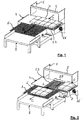
- a production line for packaging in the form of cardboard boxes includes a converting unit, such as a platen die-cutting press. As illustrated by Figures 1 and 2 , a separation unit 1 is mounted downstream of the press. The separation unit 1 comprises a receiving station 2. Boxes exit longitudinally by an endless conveyor or belt from the receiving station 2 in the form of packages or stacks 3.
- a plate element ie a sheet of cardboard
- a stack of starting plate elements thus generates ten stacks of juxtaposed boxes 3, arranged in two successive rows of five stacks. All the piles 3 are fed longitudinally (Arrow T in Figure 1 ) on a conveying unit 4, mounted downstream of the receiving station 2.
- the conveying unit 4 implements a management of stacks 3.
- one possibility of managing the ten piles 3 consists, for example, in advancing longitudinally (Arrows L in the Figures 1 and 2 ) six stacks 6, while leaving four stacks immobile 7.
- the six movable stacks 6 are sent by the conveyor unit 4 to and on a second conveyor table 8.
- the six movable stacks 6 are then sent longitudinally (Arrow C in Figure 2 ) by the conveyor table 8 to and on a receiving table 9, to be processed immediately downstream in the rest of the packaging production line (not shown).
- the four stationary stacks 7 are for example sent by the conveying unit 4 to and on the second table of conveying 8, then to and on the receiving table 9, and finally in the continuation of the packaging production line.
- These differentiated conveying operation sequences can be carried out according to the programming carried out by the operator of the platen cutting press and of the separation unit 1, according to the different formats of boxes, the number of stacks to be processed in first, and the number of stacks to process second, etc.
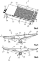
- Conveyor unit 4 includes (see Figure 3 ) a frame 11 mounted on feet 12.
- the conveying unit 4 comprises thirty transport means 13 forming a support and transfer surface for stacks 3, 6 and 7, substantially horizontal, and located in the upper part of the frame 11.
- the transport means 13 are advantageously formed by conveyor ramps 14 with endless belts 15, here twenty-nine in number.
- the transport means 13 are also formed by an endless belt 16, placed at the level of one of the lateral sides of the frame 11 and of the conveying unit 4.
- the bands 15 and therefore the ramps 14 are all identical, arranged successively side by side, adjacent and parallel to each other.
- the belt 16 is parallel to the bands 15.
- the bands 15 and the belt 16 run longitudinally (arrows B in Figures 4 and 5 ) and are suitable for transporting L packages 3, 6 and 7 in the longitudinal direction.
- the means of transport 13, ramps 14 and belt 16 comprise an upstream return 17, a downstream return 18, a lower main drive arrangement 19, and two retaining references 21 pressing the strip 15 against the drive arrangement 19.
- the references 17, 18 and 21 can also be replaced by pinions.
- the upstream return 17 and the downstream return 18 keep the strip 15 horizontal, so as to form the upper surface for holding and transferring the packages 3, 6 and 7.
- the transport means 13, ramps 14 and belt 16 comprise a support structure 22 to which are fixed the references 17, 18 and 21 and the drive arrangement 19.
- the drive arrangement 19 allows the movement B of the strip 15 and allows the transport in the longitudinal direction L.
- the drive arrangement 19 is formed with a drive pulley 23 driving the belt 15.
- the drive arrangement 19 is formed with a drive pinion 24 driving the belt 15.
- the conveying unit 4 comprises drive means, of the electric motor type 26, driving in rotation (arrow R in Figures 4 and 5 ) the drive arrangement 19, which causes the bands to travel B 15.
- the motor 26 is fixed on the frame 11, at the level of the lateral side located near the belt 16.
- the conveyor unit 4 causes L to be transported in the longitudinal direction a first package, i.e. the mobile piles 6, with the first means of transport.
- the mobile piles 6 are thus placed on and transported by a first series 27 of ramps 14.
- the conveying unit 4 leaves a second package, i.e. the immobile piles 7, with the second means of transport stationary.
- the stationary stacks 7 are thus placed on and transportable by a second series 28 of ramps 14.
- the ramp or ramps of the first series 27 and the ramp or ramps of the second series 28 are adjacent to each other.
- the number of ramps 14 of the first series 27 and of the second series 28 is variable, depending on the width of the transported 6 or stationary piles 7.
- the number of ramps 14 of the first series 27 can be equal to zero and the number of ramps 14 of the second series 28 equal to twenty-nine, in the case where only the belt 16 carries one or more stacks 6.
- the number of ramps 14 of the first series 27 may be equal to twenty- nine and the number of ramps 14 of the second series 28 equal to zero, in the case where all the stacks 6 must be transported.
- the second series 28 of ramps 14 is uncoupled from the first series 27 of ramps 14. As a result, the second series 28 is no longer driven by the motor 26 and its corresponding bands 15 no longer run longitudinally. . Conversely, the second series 28 of ramps 14 can again be coupled to the first series 27 of ramps 14.
- the conveying unit 4 comprises actuation means leaving the ramps 14 of the second series 28 longitudinally stationary with their stacks 7 stationary, relative to the ramps 14 of the first series 27 with their stacks 6.
- the actuating means first of all preferably comprise coupling means mounted on a ramp 14 of the first series 27, which is laterally the furthest from the motor 26 and from the belt 16, and which must still be driven. These means forming a coupling are able to cooperate with means forming a conjugate coupling mounted on a ramp 14 of the second series 28, which is immediately contiguous, and which is the first which must not be driven.
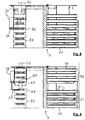
- the coupling means of the first embodiment comprises an electromechanical clutch 29 (see Figure 4 ).
- These coupling means, ie the electromechanical clutch 29, preferably form part of the drive arrangement 19, ie of the pulley 24.
- the surface of the electromechanical clutch 29 is oriented substantially perpendicular to the axis of rotation of the pulley 24. The position of the electromechanical clutch 29 allows a ramp 14 to be mechanically coupled and uncoupled with the ramp which precedes and with the ramp which follows in the series.
- the coupling means comprise a clutch 31 with laterally oriented teeth 32.
- These coupling means, ie the clutch 31, preferably form part of the drive arrangement 19, ie of the drive pinion 24.
- the teeth of the dog clutch 31 are oriented substantially perpendicular to the teeth of the drive pinion 24.
- the dog clutch 31 of the ramp 14 has two opposite sets of teeth 32, one set on each of the two faces of the pinion drive 24. The position of teeth 32 allows a ramp 14 to be mechanically coupled and uncoupled with the ramp which precedes and with the ramp which follows in the series.
- a ramp 14 or a second series 28 of ramps 14 is uncoupled from the last ramp 14 of the first series 27 by disconnecting the clutches 19 of the first embodiment or the respective dogs 31 of the second embodiment.
- the coupling means ie the electromechanical clutch 29 associated with the pulley 23, are mounted on a transverse shaft 33, which drives them in rotation R.
- the means of 'coupling ie the dogs 31 associated with the drive pinion 24, are mounted on a transverse shaft 33, on which they are able to turn R.
- the motor 26 rotates R the drive 24 of the belt 16 and the movement of rotation R is mechanically transmitted to all the drive arrangements 19, 29 and 31 of the first series of ramps 24 via the succession of clutches 19 of the first embodiment or of the dogs 31 of the second embodiment. This rotational movement R is interrupted by the decoupling of the second series of ramps 26.
- the conveying unit 4 provides a lateral offset of the first stack 6 with respect to the second stack 7 (visible in Figure 2 ). This offset prevents the two stacks 6 and 7 from staying together directly next to each other and touching each other. When the first stack 6 begins to be transported by its first series 27 of ramps 14, it does not hang on and undo the second stack 7.
- the second series 28 of ramps 14 is able to be moved apart laterally (Arrow S in the Figures 2 , 3 and 8 ) of the first series 27 of ramps 14.
- the spacing S of a series 28 of ramps 14 with respect to the other 27 generates a gap between the displaced stacks 6 and the stacks remaining immobile 7.
- the or the ramps 14 constituting the second series 28 can be moved laterally to the ramp or ramps 14 constituting the first series 27.
- the actuating means then preferably comprise spacing means, able to separate and laterally move S the second transport means with the second series 28 of ramps 14 of the first transport means with the first series 27 of ramps 14.
- a ramp 14 or a second series 28 of ramps 14 is spaced from the last ramp 14 of the first series 27 by uncoupling of the respective clutches 29 followed by lateral sliding S.
- a ramp 14 or a second series 28 of ramps 14 is moved away from the last ramp 14 of the first series 27 by lateral sliding S causing uncoupling of the respective dogs 31.
- the spacing means of the conveying unit 4 favorably comprise a carriage or mobile element 34.
- the mobile element 34 is able to move and to position itself at the level of the last ramp 14 of the first series 27 and of the first ramp 14 of the second series 28.
- the movable element 34 has the function of uncoupling and laterally moving away S the second series 28 of ramps 14 from the first series 27 of ramps 14.
- the Figures 7 to 9 show the phases of separation between two series 27 and 28 of ramps 14.
- the mobile element 34 is able to be moved (Arrow M in Figure 7 ) for example by being slidably mounted on a transverse slide.
- the slide is parallel to the transverse shaft 33.
- the movable element 34 is moved M for example by means of a belt system driven by a motor.
- the mobile element 34 is positioned to take a lateral position substantially between the first ramp 14 to be disconnected from the second series 28 and the last connected and driven ramp of the first series 27.
- the position is determined as a function of the number of ramps 14. to be not only separated but also separated laterally S.
- the movable element 34 comprises a spacer, in the form of a fork 36.
- the movable element 34 moves longitudinally (U arrow in Figure 7 ), so that the fork 36 fits longitudinally between two ramps 14.
- the fork 36 fits, for example, at the level of the two drive pinions 24 and their dog clutch 31.
- the movable element 34 is pushed U by jack.
- the fork 36 advantageously comprises two fingers 37.
- Each of the two fingers 37 is able to come into abutment against the ramps 14 to be separated, at the level of the two drive pinions 24 and of their dog clutch 31 or at the level of the holding structure 22.
- the fingers 37 move apart laterally from each other by being pushed back (Arrow J in Figure 8 ) by a jack.
- the spacing J of the fingers 37 leads to a mechanical uncoupling of the dogs 31 and to a separation of the second series 28 of ramp 14 (see Figure 9 ).
- the ramps 14 may include a lateral lifting element 38 of the transported stack 6, so as to lift and support the edge of this stack 6 (see Figure 6 ).
- the lifting element 38 is particularly useful when the stack 6 has a width greater than the width of several juxtaposed ramps 14, while the addition of an additional ramp 14 gives no support for the stack 6.
Claims (10)
- Einheit zur Förderung von Paketen, die für eine Einheit zur Transformation von einem Element in eine Platte bestimmt ist, umfassend:- ein erstes Transportmittel und mindestens ein zweites Transportmittel, wobei die Transportmittel zueinander (13, 14, 16) benachbart und parallel sind und angepasst sind Pakete (3, 6) in Längsrichtung zu transportieren (L), wobei jedes Transportmittel eine Antriebsanordnung (19) umfasst, um das Transportmittel anzutreiben, wobei die Antriebsanordnung (19) Kopplungsmittel (31) umfasst, die angepasst sind, mit den verbundenen Kopplungsmitteln (31) der Antriebsanordnung (19) des oder der benachbarten Transportmittel zusammenzuwirken, wobei jedes Transportmittel angepasst ist seitlich zu gleiten (S);- Antriebsmittel (26), um die Antriebsanordnung (19) des ersten Transportmittels (14, 27) in Rotation (R) anzutreiben, wenn die Antriebsmittel (26) und die Antriebsanordnung (19) des ersten Transportmittels (14, 27) gekoppelt sind, und- Beabstandungsmittel, die angepasst sind, eine ausgewählte Anzahl von benachbarten Transportmitteln (28) von dem Rest der benachbarten Transportmittel (27) durch seitliches Gleiten zu beabstanden oder an diesen anzunähren, wobei die Anzahl die Gesamtheit der Transportmittel darstellen kann, wenn die Gesamtheit der benachbarten Transportmittel durch seitliches Gleiten von dem Antriebsmittel (26) beabstandet oder an dieses angenähert wird, um ein erstes Paket (6), das von einer ersten Gruppe von benachbarten Antriebsmitteln (27) getragen wird, in der Längsrichtung transportieren (L) zu lassen und ein zweites Paket (7), das von einer zweiten Gruppe von benachbarten Transportmitteln (28) getragen wird, im Wesentlichen längs unbeweglich zu lassen, wenn die zweite Gruppe von benachbarten Transportmitteln (28) beabstandet ist und somit von der ersten Gruppe von benachbarten Transportmitteln (27) entkoppelt ist, die von den Antriebsmitteln (26) angetrieben werden.
- Einheit nach Anspruch 1, dadurch gekennzeichnet, dass die Kupplungsmittel eine Klauenkupplung (31) mit seitlich ausgerichteten Zähnen (32) umfassen.
- Einheit nach Anspruch 1 oder 2, dadurch gekennzeichnet, dass die Beabstandungsmittel ein bewegliches Element (34) umfassen, das angepasst ist sich zu bewegen.
- Einheit nach Anspruch 3, dadurch gekennzeichnet, dass das bewegliche Element (34) so montiert ist, dass es quer gleitet und eine seitliche Position einnimmt, abhängig von der Anzahl der Transportmittel (14, 28), die entkoppelt und seitlich beabstandet sein sollen.
- Einheit nach Anspruch 3 oder 4, dadurch gekennzeichnet, dass das bewegliche Element (34) einen Abstandshalter (36) umfasst, der angepasst ist, in Längsrichtung zwischen zwei Transportmitteln (14) bei den Kupplungsmitteln (29, 31) eingesetzt zu werden.
- Einheit nach Anspruch 5, dadurch gekennzeichnet, dass der Abstandshalter (36) zwei Finger (37) umfasst, die angepasst sind, jeweils bei den Kupplungsmitteln (29, 31) gegen die Transportmittel (14) zu stoßen und seitlich beabstandet zu sein.
- Einheit nach einem der vorhergehenden Ansprüche, dadurch gekennzeichnet, dass die Transportmittel (14) ein seitliches Hubelement (38) für das transportierte Paket (6) umfassen.
- Einheit nach einem der vorhergehenden Ansprüche, dadurch gekennzeichnet, dass sie mindestens ein Transportmittel umfasst, das seitlich befestigt (16) und bei einer der seitlichen Seiten angeordnet ist.
- Einheit nach einem der vorhergehenden Ansprüche, dadurch gekennzeichnet, dass die Transportmittel in Form von Förderrampen (14) mit einem Endlosband (15) vorliegen.
- Einheit zur Transformation von Elementen in Platten, wie beispielsweise eine Schneideinheit, die mit einer Aufnahmestation (2) in einer Linie zur Produktion von Verpackungen ausgestattet ist, dadurch gekennzeichnet, dass sie eine Einheit zur Förderung (4) gemäß einem der vorhergehenden Ansprüche umfasst, die stromabwärts von der Aufnahmestation (2) positioniert ist.
Priority Applications (1)
| Application Number | Priority Date | Filing Date | Title |
|---|---|---|---|
| EP12781042.2A EP2785619B1 (de) | 2011-12-01 | 2012-11-01 | Fördereinheit für eine verarbeitungseinheit von plattenelementen in einer produktionslinie von verpackungen |
Applications Claiming Priority (3)
| Application Number | Priority Date | Filing Date | Title |
|---|---|---|---|
| EP11009509 | 2011-12-01 | ||
| EP12781042.2A EP2785619B1 (de) | 2011-12-01 | 2012-11-01 | Fördereinheit für eine verarbeitungseinheit von plattenelementen in einer produktionslinie von verpackungen |
| PCT/EP2012/004561 WO2013079144A1 (fr) | 2011-12-01 | 2012-11-01 | Unite de convoyage de paquets pour une unite de transformation d'elements en plaque dans une ligne de production d'emballages |
Publications (2)
| Publication Number | Publication Date |
|---|---|
| EP2785619A1 EP2785619A1 (de) | 2014-10-08 |
| EP2785619B1 true EP2785619B1 (de) | 2020-12-09 |
Family
ID=47137666
Family Applications (1)
| Application Number | Title | Priority Date | Filing Date |
|---|---|---|---|
| EP12781042.2A Active EP2785619B1 (de) | 2011-12-01 | 2012-11-01 | Fördereinheit für eine verarbeitungseinheit von plattenelementen in einer produktionslinie von verpackungen |
Country Status (5)
| Country | Link |
|---|---|
| US (1) | US9315339B2 (de) |
| EP (1) | EP2785619B1 (de) |
| CN (1) | CN104093646B (de) |
| IN (1) | IN2014CN04841A (de) |
| WO (1) | WO2013079144A1 (de) |
Families Citing this family (8)
| Publication number | Priority date | Publication date | Assignee | Title |
|---|---|---|---|---|
| PT2692668E (pt) * | 2013-01-30 | 2014-07-16 | Ulma Manutencion S Coop | Aparelho e método para paletização de cargas multireferência |
| CN104787567A (zh) * | 2015-03-25 | 2015-07-22 | 韩晓钢 | 一种二维传送结构及应用该结构的传送系统 |
| FR3050134B1 (fr) * | 2016-04-18 | 2018-04-20 | Bobst Lyon | Dispositif de rupture de zones d'attache sur des boites pliables et installation de fabrication comprenant un tel dispositif de rupture |
| EP3674235B1 (de) * | 2018-12-31 | 2023-08-23 | Sparck Technologies B.V. | System und verfahren zum transportieren von artikeln zu einer verpackungsstation |
| DE102019108126A1 (de) * | 2019-03-28 | 2020-10-01 | Weber Maschinenbau Gmbh Breidenbach | Vorrichtung zum Fördern von Produkten |
| CN110815371A (zh) * | 2019-10-25 | 2020-02-21 | 福建天源兴达生物科技有限公司 | 一种琼脂条自动化生产系统 |
| CN111573383A (zh) * | 2020-04-20 | 2020-08-25 | 华龙日清纸品(许昌)有限公司 | 一种瓦楞纸盒生产线自动卸料运输设备 |
| CN112047098B (zh) * | 2020-08-26 | 2021-07-23 | 东北大学 | 一种折叠式移动及物料收集平台 |
Family Cites Families (13)
| Publication number | Priority date | Publication date | Assignee | Title |
|---|---|---|---|---|
| NL9100658A (nl) | 1991-04-15 | 1992-11-02 | Europ Patentverwertung | Opstelling van scheidingsinrichtingen. |
| US5421446A (en) * | 1993-03-12 | 1995-06-06 | United Parcel Service Of America, Inc. | Article diverter apparatus for use in conveyor systems |
| US5810149A (en) * | 1996-11-26 | 1998-09-22 | Formax, Inc. | Conveyor system |
| JP2000118671A (ja) * | 1998-10-08 | 2000-04-25 | Kubota Corp | シリンダ式コンベア装置 |
| ITBO20010772A1 (it) * | 2001-12-21 | 2003-06-21 | M C Srl | Dispositivo di trasporto a cinghia a formato registrabile |
| ES2332891T3 (es) | 2002-06-04 | 2010-02-15 | Bobst S.A. | Dispositivo para romper puntos de union que conectan hojas de carton apiladas. |
| NL1031861C2 (nl) * | 2006-05-23 | 2007-11-26 | Buhrs Zaandam Bv | Transporteursamenstel met uitwerpvoorziening, een documentverwerkingslijn voorzien van een dergelijk transporteursamenstel, alsmede een werkwijze om producten uit te werpen. |
| DE102007017035B4 (de) * | 2007-04-11 | 2017-10-19 | Alpma Alpenland Maschinenbau Gmbh | Vorrichtung zum Fördern von vereinzelten Gütern |
| DE102008023321A1 (de) * | 2008-05-13 | 2009-11-19 | Multivac Sepp Haggenmüller Gmbh & Co. Kg | Verpackungsmaschine mit einer Transportvorrichtung |
| US8167120B2 (en) * | 2008-09-22 | 2012-05-01 | Systec Corporation | Lateral load building conveyor apparatus |
| DE102010002039A1 (de) * | 2010-02-17 | 2011-08-18 | Krones Ag, 93073 | Vorrichtung zum Fördern und/oder Stauen von Artikeln |
| DE102010015839A1 (de) * | 2010-04-20 | 2011-10-20 | Bizerba Gmbh & Co. Kg | Steuerungsverfahren für einen Linienvereiniger |
| CN201785006U (zh) * | 2010-09-03 | 2011-04-06 | 广州市欧峰机电设备有限公司 | 一种链板输送线动力牵引装置 |
-
2012
- 2012-11-01 US US14/362,170 patent/US9315339B2/en active Active
- 2012-11-01 EP EP12781042.2A patent/EP2785619B1/de active Active
- 2012-11-01 CN CN201280068301.7A patent/CN104093646B/zh active Active
- 2012-11-01 IN IN4841CHN2014 patent/IN2014CN04841A/en unknown
- 2012-11-01 WO PCT/EP2012/004561 patent/WO2013079144A1/fr active Application Filing
Non-Patent Citations (1)
| Title |
|---|
| None * |
Also Published As
| Publication number | Publication date |
|---|---|
| US20140346011A1 (en) | 2014-11-27 |
| IN2014CN04841A (de) | 2015-09-18 |
| CN104093646A (zh) | 2014-10-08 |
| US9315339B2 (en) | 2016-04-19 |
| EP2785619A1 (de) | 2014-10-08 |
| WO2013079144A1 (fr) | 2013-06-06 |
| CN104093646B (zh) | 2017-03-01 |
Similar Documents
| Publication | Publication Date | Title |
|---|---|---|
| EP2785619B1 (de) | Fördereinheit für eine verarbeitungseinheit von plattenelementen in einer produktionslinie von verpackungen | |
| EP3038954B1 (de) | Verfahren zum transportieren und drehen flacher gegenstände | |
| EP2914523B1 (de) | Halterungsvorrichtung für ein plattes, blattförmiges element, das sich in einer bearbeitungsmaschine dreht | |
| EP3003703B1 (de) | Verarbeitungseinheit mit endlosbandauflage, und damit ausgestattete maschine zur herstellung von verpackungen | |
| EP3160884B1 (de) | Verfahren und vorrichtung zum zufördern von zuschnitten zu eine maschine | |
| EP0130852B1 (de) | Vorrichtung zum Anfertigen von Pappkisten in gefalteter Form | |
| FR2499040A1 (fr) | Appareil de reception et de transfert de matiere en feuille | |
| CH633761A5 (fr) | Dispositif pour empiler des objets plats, notamment des decoupes de boites pliantes. | |
| BE1005517A5 (fr) | Appareil de fabrication de sacs avec separateur-plieur. | |
| EP2704973B1 (de) | Vorrichtung zum stapeln von papierbögen oder dergleichen | |
| EP2844595B1 (de) | Verfahren zum herstellen von beutelpackungen, und dazugehörige maschine | |
| FR2612164A1 (fr) | Procede et dispositif de mise en portefeuille d'une matiere en feuille delicate a transporter | |
| WO2018192685A1 (fr) | Dispositif de recuperation d'echantillons de poses, station d'evacuation et machine de traitement d'elements en forme de feuilles | |
| EP0244308B1 (de) | Maschine zum Aufnehmen und Stapeln von geschnittenen Bögen | |
| EP0876904B1 (de) | Wendevorrichtung für eine Frontplatte in einer Falt-Beleimungsvorrichtung | |
| EP2844460B1 (de) | Modul mit gestell, und damit ausgestattete biege-klebe-presse | |
| WO2018197046A1 (fr) | Dispositif et procede d'ejection d'echantillons de poses, station d'evacuation et machine de traitement d'elements en forme de feuilles | |
| EP1528021A1 (de) | Bogenzuführvorrichtung einer Bogenverarbeitungsmaschine | |
| FR2510980A1 (fr) | Procede et appareil d'alignement de piles de feuilles | |
| FR2465597A1 (fr) | Procede et appareil pour faire avancer des feuilles ou une bande en vue d'y effectuer des impressions | |
| FR2535648A1 (fr) | Procede d'alimentation d'un margeur et installation de fabrication d'emballage en carton | |
| FR2981056A1 (fr) | Dispositif d'avance de support en forme de feuille et dispositif de traitement de support en forme de feuille | |
| JP2011098835A (ja) | 印刷物から積重ね体を形成する方法ならびに装置 | |
| FR2932172A1 (fr) | Procede de decoupage et de pliage d'une bande de papier et dispositif correspondant. | |
| FR2586097A1 (fr) | Procede et machine destines a confectionner des livres |
Legal Events
| Date | Code | Title | Description |
|---|---|---|---|
| PUAI | Public reference made under article 153(3) epc to a published international application that has entered the european phase |
Free format text: ORIGINAL CODE: 0009012 |
|
| 17P | Request for examination filed |
Effective date: 20140604 |
|
| AK | Designated contracting states |
Kind code of ref document: A1 Designated state(s): AL AT BE BG CH CY CZ DE DK EE ES FI FR GB GR HR HU IE IS IT LI LT LU LV MC MK MT NL NO PL PT RO RS SE SI SK SM TR |
|
| DAX | Request for extension of the european patent (deleted) | ||
| STAA | Information on the status of an ep patent application or granted ep patent |
Free format text: STATUS: EXAMINATION IS IN PROGRESS |
|
| 17Q | First examination report despatched |
Effective date: 20180214 |
|
| GRAP | Despatch of communication of intention to grant a patent |
Free format text: ORIGINAL CODE: EPIDOSNIGR1 |
|
| STAA | Information on the status of an ep patent application or granted ep patent |
Free format text: STATUS: GRANT OF PATENT IS INTENDED |
|
| INTG | Intention to grant announced |
Effective date: 20200616 |
|
| GRAS | Grant fee paid |
Free format text: ORIGINAL CODE: EPIDOSNIGR3 |
|
| GRAA | (expected) grant |
Free format text: ORIGINAL CODE: 0009210 |
|
| STAA | Information on the status of an ep patent application or granted ep patent |
Free format text: STATUS: THE PATENT HAS BEEN GRANTED |
|
| AK | Designated contracting states |
Kind code of ref document: B1 Designated state(s): AL AT BE BG CH CY CZ DE DK EE ES FI FR GB GR HR HU IE IS IT LI LT LU LV MC MK MT NL NO PL PT RO RS SE SI SK SM TR |
|
| REG | Reference to a national code |
Ref country code: GB Ref legal event code: FG4D Free format text: NOT ENGLISH |
|
| REG | Reference to a national code |
Ref country code: AT Ref legal event code: REF Ref document number: 1343216 Country of ref document: AT Kind code of ref document: T Effective date: 20201215 Ref country code: CH Ref legal event code: EP |
|
| REG | Reference to a national code |
Ref country code: DE Ref legal event code: R096 Ref document number: 602012073653 Country of ref document: DE |
|
| REG | Reference to a national code |
Ref country code: IE Ref legal event code: FG4D Free format text: LANGUAGE OF EP DOCUMENT: FRENCH |
|
| REG | Reference to a national code |
Ref country code: NL Ref legal event code: FP |
|
| PG25 | Lapsed in a contracting state [announced via postgrant information from national office to epo] |
Ref country code: FI Free format text: LAPSE BECAUSE OF FAILURE TO SUBMIT A TRANSLATION OF THE DESCRIPTION OR TO PAY THE FEE WITHIN THE PRESCRIBED TIME-LIMIT Effective date: 20201209 Ref country code: RS Free format text: LAPSE BECAUSE OF FAILURE TO SUBMIT A TRANSLATION OF THE DESCRIPTION OR TO PAY THE FEE WITHIN THE PRESCRIBED TIME-LIMIT Effective date: 20201209 Ref country code: NO Free format text: LAPSE BECAUSE OF FAILURE TO SUBMIT A TRANSLATION OF THE DESCRIPTION OR TO PAY THE FEE WITHIN THE PRESCRIBED TIME-LIMIT Effective date: 20210309 Ref country code: GR Free format text: LAPSE BECAUSE OF FAILURE TO SUBMIT A TRANSLATION OF THE DESCRIPTION OR TO PAY THE FEE WITHIN THE PRESCRIBED TIME-LIMIT Effective date: 20210310 |
|
| REG | Reference to a national code |
Ref country code: AT Ref legal event code: MK05 Ref document number: 1343216 Country of ref document: AT Kind code of ref document: T Effective date: 20201209 |
|
| PG25 | Lapsed in a contracting state [announced via postgrant information from national office to epo] |
Ref country code: LV Free format text: LAPSE BECAUSE OF FAILURE TO SUBMIT A TRANSLATION OF THE DESCRIPTION OR TO PAY THE FEE WITHIN THE PRESCRIBED TIME-LIMIT Effective date: 20201209 Ref country code: SE Free format text: LAPSE BECAUSE OF FAILURE TO SUBMIT A TRANSLATION OF THE DESCRIPTION OR TO PAY THE FEE WITHIN THE PRESCRIBED TIME-LIMIT Effective date: 20201209 Ref country code: BG Free format text: LAPSE BECAUSE OF FAILURE TO SUBMIT A TRANSLATION OF THE DESCRIPTION OR TO PAY THE FEE WITHIN THE PRESCRIBED TIME-LIMIT Effective date: 20210309 |
|
| PG25 | Lapsed in a contracting state [announced via postgrant information from national office to epo] |
Ref country code: HR Free format text: LAPSE BECAUSE OF FAILURE TO SUBMIT A TRANSLATION OF THE DESCRIPTION OR TO PAY THE FEE WITHIN THE PRESCRIBED TIME-LIMIT Effective date: 20201209 |
|
| REG | Reference to a national code |
Ref country code: LT Ref legal event code: MG9D |
|
| PG25 | Lapsed in a contracting state [announced via postgrant information from national office to epo] |
Ref country code: LT Free format text: LAPSE BECAUSE OF FAILURE TO SUBMIT A TRANSLATION OF THE DESCRIPTION OR TO PAY THE FEE WITHIN THE PRESCRIBED TIME-LIMIT Effective date: 20201209 Ref country code: RO Free format text: LAPSE BECAUSE OF FAILURE TO SUBMIT A TRANSLATION OF THE DESCRIPTION OR TO PAY THE FEE WITHIN THE PRESCRIBED TIME-LIMIT Effective date: 20201209 Ref country code: SK Free format text: LAPSE BECAUSE OF FAILURE TO SUBMIT A TRANSLATION OF THE DESCRIPTION OR TO PAY THE FEE WITHIN THE PRESCRIBED TIME-LIMIT Effective date: 20201209 Ref country code: PT Free format text: LAPSE BECAUSE OF FAILURE TO SUBMIT A TRANSLATION OF THE DESCRIPTION OR TO PAY THE FEE WITHIN THE PRESCRIBED TIME-LIMIT Effective date: 20210409 Ref country code: SM Free format text: LAPSE BECAUSE OF FAILURE TO SUBMIT A TRANSLATION OF THE DESCRIPTION OR TO PAY THE FEE WITHIN THE PRESCRIBED TIME-LIMIT Effective date: 20201209 Ref country code: CZ Free format text: LAPSE BECAUSE OF FAILURE TO SUBMIT A TRANSLATION OF THE DESCRIPTION OR TO PAY THE FEE WITHIN THE PRESCRIBED TIME-LIMIT Effective date: 20201209 Ref country code: EE Free format text: LAPSE BECAUSE OF FAILURE TO SUBMIT A TRANSLATION OF THE DESCRIPTION OR TO PAY THE FEE WITHIN THE PRESCRIBED TIME-LIMIT Effective date: 20201209 |
|
| PG25 | Lapsed in a contracting state [announced via postgrant information from national office to epo] |
Ref country code: PL Free format text: LAPSE BECAUSE OF FAILURE TO SUBMIT A TRANSLATION OF THE DESCRIPTION OR TO PAY THE FEE WITHIN THE PRESCRIBED TIME-LIMIT Effective date: 20201209 Ref country code: AT Free format text: LAPSE BECAUSE OF FAILURE TO SUBMIT A TRANSLATION OF THE DESCRIPTION OR TO PAY THE FEE WITHIN THE PRESCRIBED TIME-LIMIT Effective date: 20201209 |
|
| REG | Reference to a national code |
Ref country code: DE Ref legal event code: R097 Ref document number: 602012073653 Country of ref document: DE |
|
| PG25 | Lapsed in a contracting state [announced via postgrant information from national office to epo] |
Ref country code: IS Free format text: LAPSE BECAUSE OF FAILURE TO SUBMIT A TRANSLATION OF THE DESCRIPTION OR TO PAY THE FEE WITHIN THE PRESCRIBED TIME-LIMIT Effective date: 20210409 |
|
| PLBE | No opposition filed within time limit |
Free format text: ORIGINAL CODE: 0009261 |
|
| STAA | Information on the status of an ep patent application or granted ep patent |
Free format text: STATUS: NO OPPOSITION FILED WITHIN TIME LIMIT |
|
| PG25 | Lapsed in a contracting state [announced via postgrant information from national office to epo] |
Ref country code: AL Free format text: LAPSE BECAUSE OF FAILURE TO SUBMIT A TRANSLATION OF THE DESCRIPTION OR TO PAY THE FEE WITHIN THE PRESCRIBED TIME-LIMIT Effective date: 20201209 |
|
| 26N | No opposition filed |
Effective date: 20210910 |
|
| PG25 | Lapsed in a contracting state [announced via postgrant information from national office to epo] |
Ref country code: SI Free format text: LAPSE BECAUSE OF FAILURE TO SUBMIT A TRANSLATION OF THE DESCRIPTION OR TO PAY THE FEE WITHIN THE PRESCRIBED TIME-LIMIT Effective date: 20201209 Ref country code: DK Free format text: LAPSE BECAUSE OF FAILURE TO SUBMIT A TRANSLATION OF THE DESCRIPTION OR TO PAY THE FEE WITHIN THE PRESCRIBED TIME-LIMIT Effective date: 20201209 Ref country code: ES Free format text: LAPSE BECAUSE OF FAILURE TO SUBMIT A TRANSLATION OF THE DESCRIPTION OR TO PAY THE FEE WITHIN THE PRESCRIBED TIME-LIMIT Effective date: 20201209 |
|
| PG25 | Lapsed in a contracting state [announced via postgrant information from national office to epo] |
Ref country code: IS Free format text: LAPSE BECAUSE OF FAILURE TO SUBMIT A TRANSLATION OF THE DESCRIPTION OR TO PAY THE FEE WITHIN THE PRESCRIBED TIME-LIMIT Effective date: 20210409 |
|
| PG25 | Lapsed in a contracting state [announced via postgrant information from national office to epo] |
Ref country code: MC Free format text: LAPSE BECAUSE OF FAILURE TO SUBMIT A TRANSLATION OF THE DESCRIPTION OR TO PAY THE FEE WITHIN THE PRESCRIBED TIME-LIMIT Effective date: 20201209 |
|
| PG25 | Lapsed in a contracting state [announced via postgrant information from national office to epo] |
Ref country code: LU Free format text: LAPSE BECAUSE OF NON-PAYMENT OF DUE FEES Effective date: 20211101 Ref country code: BE Free format text: LAPSE BECAUSE OF NON-PAYMENT OF DUE FEES Effective date: 20211130 |
|
| REG | Reference to a national code |
Ref country code: BE Ref legal event code: MM Effective date: 20211130 |
|
| PG25 | Lapsed in a contracting state [announced via postgrant information from national office to epo] |
Ref country code: IE Free format text: LAPSE BECAUSE OF NON-PAYMENT OF DUE FEES Effective date: 20211101 |
|
| PG25 | Lapsed in a contracting state [announced via postgrant information from national office to epo] |
Ref country code: HU Free format text: LAPSE BECAUSE OF FAILURE TO SUBMIT A TRANSLATION OF THE DESCRIPTION OR TO PAY THE FEE WITHIN THE PRESCRIBED TIME-LIMIT; INVALID AB INITIO Effective date: 20121101 Ref country code: CY Free format text: LAPSE BECAUSE OF FAILURE TO SUBMIT A TRANSLATION OF THE DESCRIPTION OR TO PAY THE FEE WITHIN THE PRESCRIBED TIME-LIMIT Effective date: 20201209 |
|
| PGFP | Annual fee paid to national office [announced via postgrant information from national office to epo] |
Ref country code: NL Payment date: 20230915 Year of fee payment: 12 Ref country code: GB Payment date: 20230907 Year of fee payment: 12 |
|
| PGFP | Annual fee paid to national office [announced via postgrant information from national office to epo] |
Ref country code: IT Payment date: 20231010 Year of fee payment: 12 Ref country code: FR Payment date: 20231106 Year of fee payment: 12 Ref country code: DE Payment date: 20230906 Year of fee payment: 12 Ref country code: CH Payment date: 20231201 Year of fee payment: 12 |
|
| PG25 | Lapsed in a contracting state [announced via postgrant information from national office to epo] |
Ref country code: MK Free format text: LAPSE BECAUSE OF FAILURE TO SUBMIT A TRANSLATION OF THE DESCRIPTION OR TO PAY THE FEE WITHIN THE PRESCRIBED TIME-LIMIT Effective date: 20201209 |