EP2782687B1 - Vorrichtung zur behandlung von behältern - Google Patents
Vorrichtung zur behandlung von behältern Download PDFInfo
- Publication number
- EP2782687B1 EP2782687B1 EP12766883.8A EP12766883A EP2782687B1 EP 2782687 B1 EP2782687 B1 EP 2782687B1 EP 12766883 A EP12766883 A EP 12766883A EP 2782687 B1 EP2782687 B1 EP 2782687B1
- Authority
- EP
- European Patent Office
- Prior art keywords
- rotor
- hood
- suction extraction
- suction
- interior
- Prior art date
- Legal status (The legal status is an assumption and is not a legal conclusion. Google has not performed a legal analysis and makes no representation as to the accuracy of the status listed.)
- Not-in-force
Links
- 238000000605 extraction Methods 0.000 claims description 27
- 238000007639 printing Methods 0.000 claims description 20
- 239000000356 contaminant Substances 0.000 claims description 8
- 239000000126 substance Substances 0.000 claims description 6
- 238000000034 method Methods 0.000 claims description 5
- 230000000694 effects Effects 0.000 claims description 4
- 230000008569 process Effects 0.000 claims description 3
- 230000015572 biosynthetic process Effects 0.000 claims 1
- 230000002093 peripheral effect Effects 0.000 description 13
- 239000000976 ink Substances 0.000 description 12
- 238000001035 drying Methods 0.000 description 5
- 230000005855 radiation Effects 0.000 description 5
- 239000002904 solvent Substances 0.000 description 5
- 238000004140 cleaning Methods 0.000 description 3
- 239000007788 liquid Substances 0.000 description 3
- CBENFWSGALASAD-UHFFFAOYSA-N Ozone Chemical compound [O-][O+]=O CBENFWSGALASAD-UHFFFAOYSA-N 0.000 description 2
- 239000000969 carrier Substances 0.000 description 2
- 238000005520 cutting process Methods 0.000 description 2
- 239000000049 pigment Substances 0.000 description 2
- 230000008439 repair process Effects 0.000 description 2
- 241000446313 Lamella Species 0.000 description 1
- 230000001133 acceleration Effects 0.000 description 1
- 239000003086 colorant Substances 0.000 description 1
- 238000011109 contamination Methods 0.000 description 1
- 238000004132 cross linking Methods 0.000 description 1
- 230000007423 decrease Effects 0.000 description 1
- 238000013461 design Methods 0.000 description 1
- 238000011161 development Methods 0.000 description 1
- 230000018109 developmental process Effects 0.000 description 1
- 238000010017 direct printing Methods 0.000 description 1
- 238000009826 distribution Methods 0.000 description 1
- 238000005265 energy consumption Methods 0.000 description 1
- 238000001914 filtration Methods 0.000 description 1
- 239000010419 fine particle Substances 0.000 description 1
- 239000011521 glass Substances 0.000 description 1
- 230000036541 health Effects 0.000 description 1
- 239000012535 impurity Substances 0.000 description 1
- 238000012423 maintenance Methods 0.000 description 1
- 239000011159 matrix material Substances 0.000 description 1
- 239000002184 metal Substances 0.000 description 1
- 238000012986 modification Methods 0.000 description 1
- 230000004048 modification Effects 0.000 description 1
- 238000004806 packaging method and process Methods 0.000 description 1
- 230000008092 positive effect Effects 0.000 description 1
- 230000007704 transition Effects 0.000 description 1
- 239000002699 waste material Substances 0.000 description 1
Images


Classifications
-
- B—PERFORMING OPERATIONS; TRANSPORTING
- B41—PRINTING; LINING MACHINES; TYPEWRITERS; STAMPS
- B41J—TYPEWRITERS; SELECTIVE PRINTING MECHANISMS, i.e. MECHANISMS PRINTING OTHERWISE THAN FROM A FORME; CORRECTION OF TYPOGRAPHICAL ERRORS
- B41J3/00—Typewriters or selective printing or marking mechanisms characterised by the purpose for which they are constructed
- B41J3/407—Typewriters or selective printing or marking mechanisms characterised by the purpose for which they are constructed for marking on special material
- B41J3/4073—Printing on three-dimensional objects not being in sheet or web form, e.g. spherical or cubic objects
- B41J3/40733—Printing on cylindrical or rotationally symmetrical objects, e. g. on bottles
-
- B—PERFORMING OPERATIONS; TRANSPORTING
- B08—CLEANING
- B08B—CLEANING IN GENERAL; PREVENTION OF FOULING IN GENERAL
- B08B15/00—Preventing escape of dirt or fumes from the area where they are produced; Collecting or removing dirt or fumes from that area
- B08B15/007—Fume suction nozzles arranged on a closed or semi-closed surface, e.g. on a circular, ring-shaped or rectangular surface adjacent the area where fumes are produced
-
- B—PERFORMING OPERATIONS; TRANSPORTING
- B08—CLEANING
- B08B—CLEANING IN GENERAL; PREVENTION OF FOULING IN GENERAL
- B08B15/00—Preventing escape of dirt or fumes from the area where they are produced; Collecting or removing dirt or fumes from that area
- B08B15/02—Preventing escape of dirt or fumes from the area where they are produced; Collecting or removing dirt or fumes from that area using chambers or hoods covering the area
-
- B—PERFORMING OPERATIONS; TRANSPORTING
- B41—PRINTING; LINING MACHINES; TYPEWRITERS; STAMPS
- B41F—PRINTING MACHINES OR PRESSES
- B41F35/00—Cleaning arrangements or devices
-
- B—PERFORMING OPERATIONS; TRANSPORTING
- B41—PRINTING; LINING MACHINES; TYPEWRITERS; STAMPS
- B41J—TYPEWRITERS; SELECTIVE PRINTING MECHANISMS, i.e. MECHANISMS PRINTING OTHERWISE THAN FROM A FORME; CORRECTION OF TYPOGRAPHICAL ERRORS
- B41J3/00—Typewriters or selective printing or marking mechanisms characterised by the purpose for which they are constructed
- B41J3/407—Typewriters or selective printing or marking mechanisms characterised by the purpose for which they are constructed for marking on special material
- B41J3/4073—Printing on three-dimensional objects not being in sheet or web form, e.g. spherical or cubic objects
Definitions
- the invention relates to a device for treating containers, in particular for printing on containers, according to the preamble of patent claim 1.
- Devices for treating containers by printing the containers are known ( DE 10 2006 001 223 A1 ).
- the containers are moved on a treatment path formed by a plurality of rotors connected to transport rotors and each having a vertical machine axis and a treatment step of a treatment comprising a plurality of treatment steps takes place at the treatment positions of each rotor, for example the application of a Color set in color printing, the pretreatment of containers for printing or curing and / or crosslinking of the ink, for example by energy input, ie by heat and / or UV radiation and / or microwave radiation and / or beta radiation.
- the object of the invention is to provide a device for treating, in particular for printing containers with a suction device, which allows for high reliability and a reduced design and energy costs an effective suction of incurred in the treatment foreign or foreign matter.
- a device according to the patent claim 1 is formed.
- the suction of foreign matter or impurities takes place directly at the treatment positions, i. directly at the respective place of origin of foreign or foreign matter, via the non-rotating with the rotor and the rotor open suction hood, which extends in the rotor rotation direction at least over a treatment path corresponding angular range of rotation of the rotor or the rotor circumference.
- Air turbulence caused by the rotation of the rotor as well as by any rotation or rotation of the container during their treatment have basically no or substantially no negative effect on the suction of foreign or foreign matter, but the rotational movement of the rotor for an accelerated Removing the foreign and contaminants from the treatment positions by the centrifugal or centrifugal forces and used for accelerating the exhaust air flow and thereby at least supports the extraction of foreign or foreign matter.
- the respective exhaust hood is aerodynamically optimally designed in their hood interior in relation to the local flow conditions, and also in the sense of energy and process efficiency, in particular in such a way that an air flow which has a positive effect on the treatment or printing process is achieved with minimally injected suction energy at the treatment positions and the suction device can accordingly also be operated cost-efficiently.
- Container are in the context of the invention in particular cans, bottles, tubes, Pourches, each made of metal, glass and / or plastic, but also other packaging, which are suitable for filling of products.
- the device has, for example, a plurality of rotors or modules which connect in a container transport direction in transport moderately to each other and at the treatment positions 3 each a partial treatment is performed, for example, applying a set of colors of the multi-color imprint, preparing the container surface for printing, drying the ink, etc.
- a treatment head 5 is provided in each case, with which the respective treatment step is carried out, for example the application of a color set of the multicolor overprint.
- the treatment heads are 5 printheads and electrically operated print heads which operate specifically according to the ink-jet method, with which the ink or printing ink, ie color pigments in a liquid matrix (solvent), are controlled via nozzles to the respective treatment position 3 arranged container is applied.
- the treatment positions 3 on the rotor 1 are those for drying out the printing ink, for example by energy input, e.g. by heat, UV light, etc.
- the treatment heads 5 are at these treatment positions 3 the corresponding energy radiation emitting treatment heads, such as infrared emitters and / or UV emitters, etc.
- a non-rotating with the rotor 1 suction device 6 which encloses the rotor 1 in the rotor rotational direction A on a part of its circumference with a suction hood 7, ie i.e. to an angular range or essentially to an angular range of the rotational movement of the rotor 1 on which (angle range) the treatment of the container 2 takes place at the treatment positions 3, for example over an angular range of about 180 ° to 270 °.
- the suction hood 7 or its housing has in the direction of the machine axis MA a height at least equal to the corresponding height of the treatment positions 3.
- the housing of the suction hood 7 consists of a lower housing wall 8, an upper housing wall 9, which are arranged in the illustrated embodiment with their surface sides in planes perpendicular or substantially perpendicular to the machine axis MA, and from a outer, the machine axis MA as well as the rotor at a distance partly around closing peripheral wall 10, based on the rotor rotation direction A at the front end 7.1 of the suction hood 7 and at the rear end 7.2 of the suction hood in each case in a direction extending to the rotor 1 peripheral wall portion 10.1 ang. 10.2 passes.
- the suction hood 10 enclosing the rotor 1 on a part of its circumference and not rotating with the rotor 1 thus forms a hood interior 11, which is open in particular radially to the rotor 1.
- a large-area filter arrangement 12 in the form of at least one air filter is provided on the rear wall formed in the hood interior 11 by the peripheral wall 10.
- the chamber 7 or its interior closed to the environment is connected to a suction channel 14.1 with a suction channel 14 which has a relatively large cross-section and is formed for example by at least one tube and / or at least one tube system, with a vacuum, not shown. or suction source, for example, connected to the suction or vacuum inlet of a suction fan.
- the rotor 1 extends in the illustrated embodiment with its treatment areas 3 having peripheral area in the hood interior 11 inside. Furthermore, in the hood interior 11 lamellar and as baffles acting wall elements 15 are provided, even in the region of the two ends 7.1 and 7.2 and between these ends.
- the wall elements 15 contribute to an optimal distribution of the suction and to achieve optimum flow conditions while avoiding turbulence.
- a particularly effective suction effect at a reduced power of the suction fan connected to the exhaust duct 14 u.a. results for the suction device 6. already by the fact that the foreign or foreign matter arising during the treatment of the container 2 are already conveyed by centrifugal forces, which result from the rotation of the rotor 1, into the hood interior 1 which is open radially towards the rotor 1.
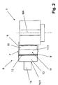
- FIGS. 4 and 5 show as a further embodiment, a suction device 6a, which can be used in place of the suction device 6 and in turn one of the suction hood 7 corresponding exhaust hood 16, the hood interior 17 is connected via a filter device with the suction channel 14 and via this with the exhaust fan, not shown.
- the suction hood 16 in turn extends over a portion of the circumference of the rotor 1 in the rotor rotational direction A, ie based on the machine axis MA over an angular range less than 360 °, for example over an angular range of about 180 ° to 270 °.
- the hood interior 17 is at the bottom by a part-annular bottom wall 18, bounded at the top by a chamber 19 and at the periphery by a peripheral wall 20, which in this embodiment partially circular cylinder surrounds the machine axis MA with distance.
- the rotor 1 is in the FIGS. 4 and 5 not shown. In these figures, however, in each case the machine axis MA is indicated, which in turn is also the axis of the rotor 1 at the same time.
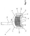
- a plurality of lamellar and acting as a guide plate wall elements 21 are provided, each extending from the lower housing wall 18 into the chamber 19, which is open on its side facing the housing bottom 18 side, but otherwise closed to the environment.
- the chamber 19 extends over the entire angular length of the suction hood 16 between the end corresponding to the end 7.1 16.1 and the End 7.2 corresponding end 16.2.
- the wall elements 21 are respectively radially or substantially radially oriented with respect to the machine axis MA with their lower end 21.1 fixed to the lower housing wall 18 and with their upper end extending into the chamber 19, but the upper end 21.2 is opposite the lower end 21.1 of each wall element 21 is offset in the rotor rotation direction A by an angular amount, which in the illustrated embodiment corresponds approximately to the pitch between two adjacent wall elements 21 or is slightly smaller than this pitch. Furthermore, the wall elements 21 are curved concavely on their front side relative to the rotor rotation direction A.
- the wall elements 21 are fastened to an additional wall element 22, which is already part of the wall of the chamber 19.
- one of the filter device 12 corresponding filter device is provided within the chamber 19, for example.
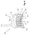
- FIGS. 6 to 9 show as another embodiment, a suction device 6b with a suction hood 7 corresponding suction hood 24, which does not rotate with the rotor 1 in the rotor rotational direction A over a portion of the rotor circumference, for example over an angular range of about 180 ° to 270 °.
- the treatment positions 3 are provided.
- the suction-type suction hood 24 which is sickle-shaped in plan view, forms a hood interior 25 which, in turn, is open radially relative to the rotor axis or relative to the machine axis MA to the circumference of the rotor 1 and through a lower housing wall 26, through an upper housing wall 27 and through a housing embodiment shown concentrically to the machine axis MA extending part-circular cylindrical peripheral wall 28 is limited.
- hood interior 25 more acting as baffles wall elements 29 are provided which extend from the lower housing wall 26 to the upper housing wall 27 and which extend to the rotor 1 adjacent edge of the housing walls 26 and 27.
- the wall elements 29 are spaced to form a suction channel 25.1, which extends within the hood interior 25 in the rotor rotation direction A from the front end 24.1 relative to this direction of rotation to the rear end 24.2 of the suction hood 24.
- the wall elements 29 are each curved about axes parallel to the machine axis MA, in such a way that the rotor 1 adjacent, extending between the housing walls 26 and 27 inner edge of each wall element 29 relative to the corresponding, the rotor 1 remote outer edge opposite Rotary direction of rotation A is offset by an angular amount, for example, the pitch of two wall elements 29 corresponds.
- the relative to the rotor rotation direction A on its front respectively convex and on its back concave curved wall elements 29 form between them flow channels 30, which open into the suction channel 25.1.
- the suction hood 24 and its housing is formed so that in the region of the end 24.1 between the suction hood 24 and the circumference of the rotor 1, an inlet funnel 31 is formed such that there over an angular range or over an angular length, which is smaller as the total length of the suction hood 24, starting from the end 24.1 initially a greater distance between the suction hood 24 and the circumference of the rotor 1, the (distance) is then reduced in the rotor rotational direction A, in the illustrated embodiment, steadily and continuously.
- a suction tube 33 which is oriented in the illustrated embodiment with its axis parallel to the machine axis MA and to which the suction channel 14, not shown, connected to the hood interior 25 inside.
- the closed at its end of the housing wall 26 end suction tube 32 is designed on its outer surface with a plurality of openings sieve-like, ie provided with a sieve-like structure 33 through which the suction channel 25.1 communicates with the interior of the suction pipe 32.
- the exhaust hood 24 is pivotable about an axis parallel to the machine axis MA, which axis is, for example, the axis of the exhaust pipe 32.
- the suction hood 24 can thus for cleaning, maintenance, repair, etc. from the in the FIG. 6 shown, the rotor 1 adjacent working position are pivoted away from the rotor 1.
- the suction device 6b corresponds to a particularly preferred embodiment of the invention, in which (embodiment) the connection for the suction channel 14 or the suction tube 32 is located at the rear end 24.2 relative to the rotor rotation direction A. Due to the structure with radially to the rotor axis protruding and recessed areas, the (structure) of the rotor 1 on the rotor circumference alone by the treatment positions 3 and their functional elements, with circulating rotor 1, an air flow within the exhaust hood 24 through the flow channels 30 and the suction channel 25.1 generated in the suction tube 32, the one rapid and complete removal or "suction" of all foreign or foreign matter with greatly reduced energy consumption of a suction tube 32 connected to the suction fan assisted.
- the peripheral wall 20 forms together with the wall elements 21 and the wall member 22 is a structural unit which is mounted on a lower housing wall 18 forming the board or on the top of the lower housing wall 18 forming table of the container treatment machine and in case of need, for example Cleaning and or repair purposes removed from the lower housing wall 18 and / or can be replaced.
- the rotor 1 is part of a device or treatment machine with a plurality of rotors 1, of which at least those on which the environment contaminating foreign substances or contaminants are released during the treatment are provided with a suction device 6, 6a or 6b , in which case a treatment step of a treatment comprising several treatment steps is then carried out on each rotor 1.
- the device or treatment machine may also have only a single rotor 1, on which then at the respective treatment positions 3, the complete treatment is performed.
Landscapes
- Engineering & Computer Science (AREA)
- Manufacturing & Machinery (AREA)
- Coating Apparatus (AREA)
- Cleaning In General (AREA)
- Extraction Or Liquid Replacement (AREA)
- Auxiliary Devices For And Details Of Packaging Control (AREA)
- Centrifugal Separators (AREA)
Applications Claiming Priority (2)
| Application Number | Priority Date | Filing Date | Title |
|---|---|---|---|
| DE102011119171A DE102011119171B3 (de) | 2011-11-23 | 2011-11-23 | Vorrichtung zur Behandlung von Behältern mit einer Absaugvorrichtung |
| PCT/EP2012/003841 WO2013075764A1 (de) | 2011-11-23 | 2012-09-13 | Vorrichtung zur behandlung von behältern |
Publications (2)
| Publication Number | Publication Date |
|---|---|
| EP2782687A1 EP2782687A1 (de) | 2014-10-01 |
| EP2782687B1 true EP2782687B1 (de) | 2016-03-02 |
Family
ID=46968128
Family Applications (1)
| Application Number | Title | Priority Date | Filing Date |
|---|---|---|---|
| EP12766883.8A Not-in-force EP2782687B1 (de) | 2011-11-23 | 2012-09-13 | Vorrichtung zur behandlung von behältern |
Country Status (6)
Families Citing this family (11)
| Publication number | Priority date | Publication date | Assignee | Title |
|---|---|---|---|---|
| DE102011113150A1 (de) * | 2011-09-14 | 2013-03-14 | Khs Gmbh | Verfahren sowie Vorrichtung zum Behandeln von Packmitteln durch Aufbringen von Ausstattungen |
| DE102012214349A1 (de) | 2012-08-13 | 2014-02-13 | Krones Aktiengesellschaft | Druckvorrichtung, Druckkopf hierfür und Verfahren zum Absaugen von Druckfarbe |
| DE102013205232A1 (de) | 2013-03-25 | 2014-09-25 | Krones Ag | Druckvorrichtung zum Bedrucken von Behältern |
| DE102013217659A1 (de) * | 2013-09-04 | 2015-03-05 | Krones Ag | Behälterbehandlungsmaschine zur Bedruckung von Behältern |
| DE102013217663B4 (de) * | 2013-09-04 | 2023-11-02 | Krones Ag | Direktdruckmaschine mit zwei Kühlsystemen |
| CN105881886A (zh) * | 2016-05-11 | 2016-08-24 | 天津市天鹏建筑器材有限公司 | 一种带有吸气嘴的塑料管材的热熔连接机构 |
| JP6934604B2 (ja) * | 2016-05-30 | 2021-09-15 | パナソニックIpマネジメント株式会社 | 熱伝導シートおよびこれを用いたシート状ヒータ |
| DE202016103010U1 (de) * | 2016-06-07 | 2017-09-09 | Krones Ag | Vorrichtung zum Tintenstrahl-Direktbedrucken von Behältern |
| DE102017215434A1 (de) * | 2017-09-04 | 2019-03-07 | Krones Ag | Klimatisierung von Direktdruckmaschinen |
| CN110538520A (zh) * | 2019-09-25 | 2019-12-06 | 重庆青年职业技术学院 | 一种打印机的臭氧稀释旋风除尘装置 |
| CN115366538B (zh) * | 2022-09-13 | 2023-10-24 | 郑州戴纳光电技术有限公司 | 一种uv油墨喷码机 |
Family Cites Families (24)
| Publication number | Priority date | Publication date | Assignee | Title |
|---|---|---|---|---|
| GB986538A (en) * | 1962-09-20 | 1965-03-17 | Pneumatic Scale Corp | Container cleaning machine |
| DE2322219A1 (de) * | 1973-05-03 | 1974-11-14 | Winterwerb Streng Co Gmbh | Verfahren und vorrichtung zur entfernung von etiketten und schraubverschluessen von behaeltern, wie flaschen o.dgl |
| DE2755131C2 (de) * | 1977-12-10 | 1982-12-16 | Voith Transmit GmbH, 4330 Mülheim | Kupplung zum starren Verbinden zweier gleichachsiger und zum Übertragen von Drehmoment geeigneter Maschinenteile |
| DE3812678C3 (de) * | 1988-04-16 | 1996-04-11 | Heidelberger Druckmasch Ag | Vorrichtung zum Reinigen von zylindrischen Mantelflächen in Rotationsdruckmaschinen |
| DE58901892D1 (de) * | 1989-01-26 | 1992-08-27 | Rieter Ag Maschf | Reinigungsmaschine fuer textilfasern. |
| US5150502A (en) * | 1989-04-14 | 1992-09-29 | Roberson James H | Textile fiber length sorting apparatus and method |
| ES2075512T3 (es) * | 1992-03-27 | 1995-10-01 | Schablonentechnik Kufstein Ag | Dispositivo para el mecanizado de cilindros huecos de paredes finas mediante un rayo laser. |
| DE9303813U1 (de) * | 1993-03-16 | 1993-08-05 | Technologie-Zentrum Holzwirtschaft GmbH, 32657 Lemgo | Absaugelement für Späne, Stäube oder dgl. |
| DE4439081A1 (de) * | 1994-11-02 | 1996-05-09 | Kronseder Maschf Krones | Verfahren und Vorrichtung zum Entfernen von Ausstattungsmaterial von Gefäßen |
| US5540152A (en) * | 1995-04-10 | 1996-07-30 | Demoore; Howard W. | Delivery conveyor with control window ventilation and extraction system |
| JP4165694B2 (ja) * | 2002-09-11 | 2008-10-15 | ゼネラルパッカー株式会社 | 飲料用被抽出材料の抽出バッグへの包装方法 |
| US6960124B2 (en) * | 2003-01-31 | 2005-11-01 | Wy Peron Lee | Cutting machine with environment control arrangement |
| DE10355996A1 (de) * | 2003-11-27 | 2005-06-30 | Stork Prints Austria Gmbh | Verfahren zur Herstellung von Flexodruckplatten mittels Lasergravur sowie dazu ge-eignete Vorrichtung |
| DE102006001223A1 (de) * | 2006-01-10 | 2007-07-12 | Khs Ag | Vorrichtung zum Bedrucken von Flaschen oder dergleichen Behälter |
| DE102006053821A1 (de) * | 2006-11-14 | 2008-05-15 | Francotyp-Postalia Gmbh | Druckeinrichtung mit Tintennebelabsaugung |
| DE102006058955B4 (de) * | 2006-12-12 | 2014-07-24 | DüRR DENTAL AG | Saugvorrichtung für dentale, medizinische und industrielle Zwecke |
| JP2008213310A (ja) * | 2007-03-05 | 2008-09-18 | Canon Inc | 記録装置 |
| DE102008013174B3 (de) * | 2008-03-07 | 2009-12-17 | Robert Thomas Metall- Und Elektrowerke Gmbh & Co. Kg | Drehlüfter |
| DE102008049241A1 (de) * | 2008-09-26 | 2010-04-08 | Khs Ag | Vorrichtung zum Aufbringen jeweils eines Mehrfachdrucks auf Packmittel |
| DE102009013477B4 (de) * | 2009-03-19 | 2012-01-12 | Khs Gmbh | Druckvorrichtung zum Bedrucken von Flaschen oder dergleichen Behältern |
| DE102009033134B3 (de) * | 2009-07-15 | 2010-12-02 | Netstal-Maschinen Ag | Verfahren und Vorrichtung zur Absaugung von Dämpfen bei einer Spritzgießmaschine |
| DE102009043497B4 (de) * | 2009-09-30 | 2012-05-31 | Khs Gmbh | Vorrichtung zum Behandeln von Packmitteln |
| DE102010013100A1 (de) * | 2009-11-06 | 2011-05-12 | Christian Maass | Feinstaubabsaugeeinrichtung |
| DE102010051539A1 (de) * | 2010-11-18 | 2012-05-24 | Murrplastik Systemtechnik Gmbh | Vorrichtung zur Beschriftung von Kennzeichnungsschildern |
-
2011
- 2011-11-23 DE DE102011119171A patent/DE102011119171B3/de not_active Expired - Fee Related
-
2012
- 2012-09-13 US US14/358,344 patent/US9162440B2/en not_active Expired - Fee Related
- 2012-09-13 EP EP12766883.8A patent/EP2782687B1/de not_active Not-in-force
- 2012-09-13 CN CN201280051675.8A patent/CN103906582B/zh not_active Expired - Fee Related
- 2012-09-13 WO PCT/EP2012/003841 patent/WO2013075764A1/de active Application Filing
- 2012-09-13 JP JP2014542721A patent/JP6120866B2/ja active Active
Also Published As
| Publication number | Publication date |
|---|---|
| CN103906582B (zh) | 2015-11-25 |
| CN103906582A (zh) | 2014-07-02 |
| JP6120866B2 (ja) | 2017-04-26 |
| DE102011119171B3 (de) | 2013-02-21 |
| WO2013075764A1 (de) | 2013-05-30 |
| US20140290515A1 (en) | 2014-10-02 |
| EP2782687A1 (de) | 2014-10-01 |
| US9162440B2 (en) | 2015-10-20 |
| JP2015506880A (ja) | 2015-03-05 |
Similar Documents
| Publication | Publication Date | Title |
|---|---|---|
| EP2782687B1 (de) | Vorrichtung zur behandlung von behältern | |
| EP2250026B1 (de) | Druckvorrichtung zum bedrucken von flaschen oder dergleichen behältern | |
| EP2207684B1 (de) | Vorrichtung zum bedrucken von flaschen oder dergleichen behältern an der behälteraussenfläche | |
| DE102009020702B4 (de) | Drucksystem zum Bedrucken von Flaschen oder dergleichen Behältern sowie Druckvorrichtung oder -maschine mit einem solchen Drucksystem | |
| EP2059352B1 (de) | Verfahren zur behandlung von flaschen oder dergleichen behälter in einer reinigungsmaschine sowie reinigungsmaschine | |
| EP3055137B1 (de) | Taktweise arbeitende druckmaschine | |
| EP3044001B1 (de) | Drucksystem und druckvorrichtung für flaschen oder behälter mit mehrteiligem versorgungstank sowie verfahren | |
| EP2845738B1 (de) | Vorrichtung zum Bedrucken von Behältern | |
| EP2698256B2 (de) | Druckvorrichtung, Druckkopf hierfür und Verfahren zum Absaugen von Druckfarbe | |
| EP3044005B1 (de) | Vorrichtung zum bedrucken von rotationsasymmetrischen behältern | |
| DE102013214934A1 (de) | Vorrichtung und Verfahren zum Direktbedrucken von Behältern | |
| EP3103538A1 (de) | Dünnschichtverdampfer | |
| WO2013178675A1 (de) | Zusatz-druckeinrichtung in einer bogendruckmaschine | |
| DE102008002048B4 (de) | Verwendung einer Reinigungsanlagen zum Reinigen einer oder mehrere Druckwerkszylinder einer Druckeinheit einer Druckmaschine | |
| EP2289640B1 (de) | Spritzvorrichtung | |
| DE102007050493A1 (de) | Vorrichtung zum Bedrucken von Flaschen oder dergleichen Behältern an der Behälteraußenfläche | |
| DE102012218049B4 (de) | Vorrichtung zum Wenden und Fördern von Bogen in Druckmaschinen | |
| DE102008049296A1 (de) | Vorrichtung zum Abblasen oder Trocknen von Kästen oder dergleichen Behältern | |
| DE102014115866A1 (de) | Einrichtung zur Farbwerksbelüftung | |
| DE102007027385B4 (de) | Farbkammer für ein Farbwerk einer Rotationsdruckmaschine und Verfahren zur Herstellung einer solchen Farbkammer | |
| DE2807725C2 (de) | Vakuumtrockner, insbesondere zur Vortrocknung von Substanzen mit einem im Vergleich zur Flüssigkeit geringen Feststoffgehalt | |
| WO1988004950A1 (en) | Rotor for centrifugal separators used for degassing liquids | |
| EP2825383B1 (de) | Behälterbehandlungsmaschine mit feuchtwerk mit rotierender bürste | |
| DE202018006038U1 (de) | Vorrichtung zum Entgasen eines flüssigen bis pastösen Mediums, insbesondere einer Streichfarbe | |
| DE102009001510A1 (de) | Bogenverarbeitungsmaschine |
Legal Events
| Date | Code | Title | Description |
|---|---|---|---|
| PUAI | Public reference made under article 153(3) epc to a published international application that has entered the european phase |
Free format text: ORIGINAL CODE: 0009012 |
|
| 17P | Request for examination filed |
Effective date: 20140623 |
|
| AK | Designated contracting states |
Kind code of ref document: A1 Designated state(s): AL AT BE BG CH CY CZ DE DK EE ES FI FR GB GR HR HU IE IS IT LI LT LU LV MC MK MT NL NO PL PT RO RS SE SI SK SM TR |
|
| DAX | Request for extension of the european patent (deleted) | ||
| GRAP | Despatch of communication of intention to grant a patent |
Free format text: ORIGINAL CODE: EPIDOSNIGR1 |
|
| RIC1 | Information provided on ipc code assigned before grant |
Ipc: B41J 3/407 20060101ALI20150818BHEP Ipc: B08B 15/02 20060101ALI20150818BHEP Ipc: B08B 15/00 20060101AFI20150818BHEP Ipc: B41F 35/00 20060101ALI20150818BHEP |
|
| INTG | Intention to grant announced |
Effective date: 20150915 |
|
| GRAS | Grant fee paid |
Free format text: ORIGINAL CODE: EPIDOSNIGR3 |
|
| GRAA | (expected) grant |
Free format text: ORIGINAL CODE: 0009210 |
|
| AK | Designated contracting states |
Kind code of ref document: B1 Designated state(s): AL AT BE BG CH CY CZ DE DK EE ES FI FR GB GR HR HU IE IS IT LI LT LU LV MC MK MT NL NO PL PT RO RS SE SI SK SM TR |
|
| REG | Reference to a national code |
Ref country code: GB Ref legal event code: FG4D Free format text: NOT ENGLISH |
|
| REG | Reference to a national code |
Ref country code: AT Ref legal event code: REF Ref document number: 777632 Country of ref document: AT Kind code of ref document: T Effective date: 20160315 Ref country code: CH Ref legal event code: EP |
|
| REG | Reference to a national code |
Ref country code: IE Ref legal event code: FG4D Free format text: LANGUAGE OF EP DOCUMENT: GERMAN |
|
| REG | Reference to a national code |
Ref country code: DE Ref legal event code: R096 Ref document number: 502012006165 Country of ref document: DE |
|
| REG | Reference to a national code |
Ref country code: NL Ref legal event code: FP |
|
| REG | Reference to a national code |
Ref country code: LT Ref legal event code: MG4D |
|
| PG25 | Lapsed in a contracting state [announced via postgrant information from national office to epo] |
Ref country code: NO Free format text: LAPSE BECAUSE OF FAILURE TO SUBMIT A TRANSLATION OF THE DESCRIPTION OR TO PAY THE FEE WITHIN THE PRESCRIBED TIME-LIMIT Effective date: 20160602 Ref country code: ES Free format text: LAPSE BECAUSE OF FAILURE TO SUBMIT A TRANSLATION OF THE DESCRIPTION OR TO PAY THE FEE WITHIN THE PRESCRIBED TIME-LIMIT Effective date: 20160302 Ref country code: GR Free format text: LAPSE BECAUSE OF FAILURE TO SUBMIT A TRANSLATION OF THE DESCRIPTION OR TO PAY THE FEE WITHIN THE PRESCRIBED TIME-LIMIT Effective date: 20160603 Ref country code: FI Free format text: LAPSE BECAUSE OF FAILURE TO SUBMIT A TRANSLATION OF THE DESCRIPTION OR TO PAY THE FEE WITHIN THE PRESCRIBED TIME-LIMIT Effective date: 20160302 Ref country code: HR Free format text: LAPSE BECAUSE OF FAILURE TO SUBMIT A TRANSLATION OF THE DESCRIPTION OR TO PAY THE FEE WITHIN THE PRESCRIBED TIME-LIMIT Effective date: 20160302 |
|
| PG25 | Lapsed in a contracting state [announced via postgrant information from national office to epo] |
Ref country code: RS Free format text: LAPSE BECAUSE OF FAILURE TO SUBMIT A TRANSLATION OF THE DESCRIPTION OR TO PAY THE FEE WITHIN THE PRESCRIBED TIME-LIMIT Effective date: 20160302 Ref country code: SE Free format text: LAPSE BECAUSE OF FAILURE TO SUBMIT A TRANSLATION OF THE DESCRIPTION OR TO PAY THE FEE WITHIN THE PRESCRIBED TIME-LIMIT Effective date: 20160302 Ref country code: LV Free format text: LAPSE BECAUSE OF FAILURE TO SUBMIT A TRANSLATION OF THE DESCRIPTION OR TO PAY THE FEE WITHIN THE PRESCRIBED TIME-LIMIT Effective date: 20160302 Ref country code: LT Free format text: LAPSE BECAUSE OF FAILURE TO SUBMIT A TRANSLATION OF THE DESCRIPTION OR TO PAY THE FEE WITHIN THE PRESCRIBED TIME-LIMIT Effective date: 20160302 Ref country code: PL Free format text: LAPSE BECAUSE OF FAILURE TO SUBMIT A TRANSLATION OF THE DESCRIPTION OR TO PAY THE FEE WITHIN THE PRESCRIBED TIME-LIMIT Effective date: 20160302 |
|
| PG25 | Lapsed in a contracting state [announced via postgrant information from national office to epo] |
Ref country code: IS Free format text: LAPSE BECAUSE OF FAILURE TO SUBMIT A TRANSLATION OF THE DESCRIPTION OR TO PAY THE FEE WITHIN THE PRESCRIBED TIME-LIMIT Effective date: 20160702 Ref country code: EE Free format text: LAPSE BECAUSE OF FAILURE TO SUBMIT A TRANSLATION OF THE DESCRIPTION OR TO PAY THE FEE WITHIN THE PRESCRIBED TIME-LIMIT Effective date: 20160302 |
|
| PG25 | Lapsed in a contracting state [announced via postgrant information from national office to epo] |
Ref country code: RO Free format text: LAPSE BECAUSE OF FAILURE TO SUBMIT A TRANSLATION OF THE DESCRIPTION OR TO PAY THE FEE WITHIN THE PRESCRIBED TIME-LIMIT Effective date: 20160302 Ref country code: SK Free format text: LAPSE BECAUSE OF FAILURE TO SUBMIT A TRANSLATION OF THE DESCRIPTION OR TO PAY THE FEE WITHIN THE PRESCRIBED TIME-LIMIT Effective date: 20160302 Ref country code: CZ Free format text: LAPSE BECAUSE OF FAILURE TO SUBMIT A TRANSLATION OF THE DESCRIPTION OR TO PAY THE FEE WITHIN THE PRESCRIBED TIME-LIMIT Effective date: 20160302 Ref country code: PT Free format text: LAPSE BECAUSE OF FAILURE TO SUBMIT A TRANSLATION OF THE DESCRIPTION OR TO PAY THE FEE WITHIN THE PRESCRIBED TIME-LIMIT Effective date: 20160704 Ref country code: SM Free format text: LAPSE BECAUSE OF FAILURE TO SUBMIT A TRANSLATION OF THE DESCRIPTION OR TO PAY THE FEE WITHIN THE PRESCRIBED TIME-LIMIT Effective date: 20160302 |
|
| REG | Reference to a national code |
Ref country code: DE Ref legal event code: R097 Ref document number: 502012006165 Country of ref document: DE |
|
| PLBE | No opposition filed within time limit |
Free format text: ORIGINAL CODE: 0009261 |
|
| STAA | Information on the status of an ep patent application or granted ep patent |
Free format text: STATUS: NO OPPOSITION FILED WITHIN TIME LIMIT |
|
| PG25 | Lapsed in a contracting state [announced via postgrant information from national office to epo] |
Ref country code: DK Free format text: LAPSE BECAUSE OF FAILURE TO SUBMIT A TRANSLATION OF THE DESCRIPTION OR TO PAY THE FEE WITHIN THE PRESCRIBED TIME-LIMIT Effective date: 20160302 |
|
| 26N | No opposition filed |
Effective date: 20161205 |
|
| PG25 | Lapsed in a contracting state [announced via postgrant information from national office to epo] |
Ref country code: SI Free format text: LAPSE BECAUSE OF FAILURE TO SUBMIT A TRANSLATION OF THE DESCRIPTION OR TO PAY THE FEE WITHIN THE PRESCRIBED TIME-LIMIT Effective date: 20160302 Ref country code: BG Free format text: LAPSE BECAUSE OF FAILURE TO SUBMIT A TRANSLATION OF THE DESCRIPTION OR TO PAY THE FEE WITHIN THE PRESCRIBED TIME-LIMIT Effective date: 20160602 |
|
| PG25 | Lapsed in a contracting state [announced via postgrant information from national office to epo] |
Ref country code: MC Free format text: LAPSE BECAUSE OF FAILURE TO SUBMIT A TRANSLATION OF THE DESCRIPTION OR TO PAY THE FEE WITHIN THE PRESCRIBED TIME-LIMIT Effective date: 20160302 |
|
| REG | Reference to a national code |
Ref country code: CH Ref legal event code: PL |
|
| REG | Reference to a national code |
Ref country code: IE Ref legal event code: MM4A |
|
| REG | Reference to a national code |
Ref country code: FR Ref legal event code: ST Effective date: 20170531 |
|
| PG25 | Lapsed in a contracting state [announced via postgrant information from national office to epo] |
Ref country code: CH Free format text: LAPSE BECAUSE OF NON-PAYMENT OF DUE FEES Effective date: 20160930 Ref country code: FR Free format text: LAPSE BECAUSE OF NON-PAYMENT OF DUE FEES Effective date: 20160930 Ref country code: LI Free format text: LAPSE BECAUSE OF NON-PAYMENT OF DUE FEES Effective date: 20160930 Ref country code: IE Free format text: LAPSE BECAUSE OF NON-PAYMENT OF DUE FEES Effective date: 20160913 |
|
| PG25 | Lapsed in a contracting state [announced via postgrant information from national office to epo] |
Ref country code: LU Free format text: LAPSE BECAUSE OF NON-PAYMENT OF DUE FEES Effective date: 20160913 |
|
| PG25 | Lapsed in a contracting state [announced via postgrant information from national office to epo] |
Ref country code: HU Free format text: LAPSE BECAUSE OF FAILURE TO SUBMIT A TRANSLATION OF THE DESCRIPTION OR TO PAY THE FEE WITHIN THE PRESCRIBED TIME-LIMIT; INVALID AB INITIO Effective date: 20120913 |
|
| PG25 | Lapsed in a contracting state [announced via postgrant information from national office to epo] |
Ref country code: MK Free format text: LAPSE BECAUSE OF FAILURE TO SUBMIT A TRANSLATION OF THE DESCRIPTION OR TO PAY THE FEE WITHIN THE PRESCRIBED TIME-LIMIT Effective date: 20160302 Ref country code: CY Free format text: LAPSE BECAUSE OF FAILURE TO SUBMIT A TRANSLATION OF THE DESCRIPTION OR TO PAY THE FEE WITHIN THE PRESCRIBED TIME-LIMIT Effective date: 20160302 Ref country code: MT Free format text: LAPSE BECAUSE OF FAILURE TO SUBMIT A TRANSLATION OF THE DESCRIPTION OR TO PAY THE FEE WITHIN THE PRESCRIBED TIME-LIMIT Effective date: 20160302 |
|
| PG25 | Lapsed in a contracting state [announced via postgrant information from national office to epo] |
Ref country code: AL Free format text: LAPSE BECAUSE OF FAILURE TO SUBMIT A TRANSLATION OF THE DESCRIPTION OR TO PAY THE FEE WITHIN THE PRESCRIBED TIME-LIMIT Effective date: 20160302 Ref country code: TR Free format text: LAPSE BECAUSE OF FAILURE TO SUBMIT A TRANSLATION OF THE DESCRIPTION OR TO PAY THE FEE WITHIN THE PRESCRIBED TIME-LIMIT Effective date: 20160302 |
|
| REG | Reference to a national code |
Ref country code: AT Ref legal event code: MM01 Ref document number: 777632 Country of ref document: AT Kind code of ref document: T Effective date: 20170913 |
|
| PG25 | Lapsed in a contracting state [announced via postgrant information from national office to epo] |
Ref country code: AT Free format text: LAPSE BECAUSE OF NON-PAYMENT OF DUE FEES Effective date: 20170913 |
|
| PGFP | Annual fee paid to national office [announced via postgrant information from national office to epo] |
Ref country code: NL Payment date: 20190918 Year of fee payment: 8 Ref country code: IT Payment date: 20190925 Year of fee payment: 8 Ref country code: DE Payment date: 20190918 Year of fee payment: 8 |
|
| PGFP | Annual fee paid to national office [announced via postgrant information from national office to epo] |
Ref country code: BE Payment date: 20190918 Year of fee payment: 8 |
|
| PGFP | Annual fee paid to national office [announced via postgrant information from national office to epo] |
Ref country code: GB Payment date: 20190920 Year of fee payment: 8 |
|
| REG | Reference to a national code |
Ref country code: DE Ref legal event code: R119 Ref document number: 502012006165 Country of ref document: DE |
|
| REG | Reference to a national code |
Ref country code: NL Ref legal event code: MM Effective date: 20201001 |
|
| GBPC | Gb: european patent ceased through non-payment of renewal fee |
Effective date: 20200913 |
|
| REG | Reference to a national code |
Ref country code: BE Ref legal event code: MM Effective date: 20200930 |
|
| PG25 | Lapsed in a contracting state [announced via postgrant information from national office to epo] |
Ref country code: NL Free format text: LAPSE BECAUSE OF NON-PAYMENT OF DUE FEES Effective date: 20201001 |
|
| PG25 | Lapsed in a contracting state [announced via postgrant information from national office to epo] |
Ref country code: DE Free format text: LAPSE BECAUSE OF NON-PAYMENT OF DUE FEES Effective date: 20210401 |
|
| PG25 | Lapsed in a contracting state [announced via postgrant information from national office to epo] |
Ref country code: BE Free format text: LAPSE BECAUSE OF NON-PAYMENT OF DUE FEES Effective date: 20200930 Ref country code: GB Free format text: LAPSE BECAUSE OF NON-PAYMENT OF DUE FEES Effective date: 20200913 |
|
| PG25 | Lapsed in a contracting state [announced via postgrant information from national office to epo] |
Ref country code: IT Free format text: LAPSE BECAUSE OF NON-PAYMENT OF DUE FEES Effective date: 20200913 |