EP2780639B2 - Luftentfeuchter - Google Patents
Luftentfeuchter Download PDFInfo
- Publication number
- EP2780639B2 EP2780639B2 EP12703831.3A EP12703831A EP2780639B2 EP 2780639 B2 EP2780639 B2 EP 2780639B2 EP 12703831 A EP12703831 A EP 12703831A EP 2780639 B2 EP2780639 B2 EP 2780639B2
- Authority
- EP
- European Patent Office
- Prior art keywords
- tablet
- cover
- sorption
- suspension means
- opening
- Prior art date
- Legal status (The legal status is an assumption and is not a legal conclusion. Google has not performed a legal analysis and makes no representation as to the accuracy of the status listed.)
- Active
Links
- 238000001179 sorption measurement Methods 0.000 claims description 87
- 238000009423 ventilation Methods 0.000 claims description 79
- 239000000725 suspension Substances 0.000 claims description 18
- 238000007791 dehumidification Methods 0.000 claims 2
- 239000003570 air Substances 0.000 description 59
- 125000006850 spacer group Chemical group 0.000 description 28
- FAPWRFPIFSIZLT-UHFFFAOYSA-M Sodium chloride Chemical compound [Na+].[Cl-] FAPWRFPIFSIZLT-UHFFFAOYSA-M 0.000 description 10
- 239000000243 solution Substances 0.000 description 9
- 239000003795 chemical substances by application Substances 0.000 description 7
- 239000000758 substrate Substances 0.000 description 7
- TWRXJAOTZQYOKJ-UHFFFAOYSA-L Magnesium chloride Chemical compound [Mg+2].[Cl-].[Cl-] TWRXJAOTZQYOKJ-UHFFFAOYSA-L 0.000 description 6
- 230000008901 benefit Effects 0.000 description 6
- UXVMQQNJUSDDNG-UHFFFAOYSA-L Calcium chloride Chemical compound [Cl-].[Cl-].[Ca+2] UXVMQQNJUSDDNG-UHFFFAOYSA-L 0.000 description 4
- 239000001110 calcium chloride Substances 0.000 description 4
- 229910001628 calcium chloride Inorganic materials 0.000 description 4
- 238000011161 development Methods 0.000 description 4
- 230000018109 developmental process Effects 0.000 description 4
- 238000010521 absorption reaction Methods 0.000 description 3
- 238000005273 aeration Methods 0.000 description 3
- 229910001629 magnesium chloride Inorganic materials 0.000 description 3
- 230000002093 peripheral effect Effects 0.000 description 3
- 239000000843 powder Substances 0.000 description 3
- 230000003014 reinforcing effect Effects 0.000 description 3
- 230000004888 barrier function Effects 0.000 description 2
- 239000008187 granular material Substances 0.000 description 2
- 230000005484 gravity Effects 0.000 description 2
- 239000003230 hygroscopic agent Substances 0.000 description 2
- 238000004519 manufacturing process Methods 0.000 description 2
- 239000000463 material Substances 0.000 description 2
- 238000000034 method Methods 0.000 description 2
- 239000000203 mixture Substances 0.000 description 2
- 238000003825 pressing Methods 0.000 description 2
- 230000008569 process Effects 0.000 description 2
- VYPSYNLAJGMNEJ-UHFFFAOYSA-N Silicium dioxide Chemical compound O=[Si]=O VYPSYNLAJGMNEJ-UHFFFAOYSA-N 0.000 description 1
- 239000012080 ambient air Substances 0.000 description 1
- 239000007864 aqueous solution Substances 0.000 description 1
- 230000007423 decrease Effects 0.000 description 1
- 230000006735 deficit Effects 0.000 description 1
- 230000001419 dependent effect Effects 0.000 description 1
- 210000003746 feather Anatomy 0.000 description 1
- 239000000499 gel Substances 0.000 description 1
- 238000007373 indentation Methods 0.000 description 1
- 230000007246 mechanism Effects 0.000 description 1
- TWNQGVIAIRXVLR-UHFFFAOYSA-N oxo(oxoalumanyloxy)alumane Chemical compound O=[Al]O[Al]=O TWNQGVIAIRXVLR-UHFFFAOYSA-N 0.000 description 1
- 239000005022 packaging material Substances 0.000 description 1
- 238000004806 packaging method and process Methods 0.000 description 1
- 230000036316 preload Effects 0.000 description 1
- 230000000284 resting effect Effects 0.000 description 1
- 239000000741 silica gel Substances 0.000 description 1
- 229910002027 silica gel Inorganic materials 0.000 description 1
- 238000003860 storage Methods 0.000 description 1
- 239000013589 supplement Substances 0.000 description 1
- 230000007704 transition Effects 0.000 description 1
- XLYOFNOQVPJJNP-UHFFFAOYSA-N water Substances O XLYOFNOQVPJJNP-UHFFFAOYSA-N 0.000 description 1
Images


Classifications
-
- F—MECHANICAL ENGINEERING; LIGHTING; HEATING; WEAPONS; BLASTING
- F24—HEATING; RANGES; VENTILATING
- F24F—AIR-CONDITIONING; AIR-HUMIDIFICATION; VENTILATION; USE OF AIR CURRENTS FOR SCREENING
- F24F3/00—Air-conditioning systems in which conditioned primary air is supplied from one or more central stations to distributing units in the rooms or spaces where it may receive secondary treatment; Apparatus specially designed for such systems
- F24F3/12—Air-conditioning systems in which conditioned primary air is supplied from one or more central stations to distributing units in the rooms or spaces where it may receive secondary treatment; Apparatus specially designed for such systems characterised by the treatment of the air otherwise than by heating and cooling
- F24F3/14—Air-conditioning systems in which conditioned primary air is supplied from one or more central stations to distributing units in the rooms or spaces where it may receive secondary treatment; Apparatus specially designed for such systems characterised by the treatment of the air otherwise than by heating and cooling by humidification; by dehumidification
- F24F3/1411—Air-conditioning systems in which conditioned primary air is supplied from one or more central stations to distributing units in the rooms or spaces where it may receive secondary treatment; Apparatus specially designed for such systems characterised by the treatment of the air otherwise than by heating and cooling by humidification; by dehumidification by absorbing or adsorbing water, e.g. using an hygroscopic desiccant
-
- B—PERFORMING OPERATIONS; TRANSPORTING
- B01—PHYSICAL OR CHEMICAL PROCESSES OR APPARATUS IN GENERAL
- B01D—SEPARATION
- B01D53/00—Separation of gases or vapours; Recovering vapours of volatile solvents from gases; Chemical or biological purification of waste gases, e.g. engine exhaust gases, smoke, fumes, flue gases, aerosols
- B01D53/26—Drying gases or vapours
- B01D53/261—Drying gases or vapours by adsorption
-
- F—MECHANICAL ENGINEERING; LIGHTING; HEATING; WEAPONS; BLASTING
- F24—HEATING; RANGES; VENTILATING
- F24F—AIR-CONDITIONING; AIR-HUMIDIFICATION; VENTILATION; USE OF AIR CURRENTS FOR SCREENING
- F24F3/00—Air-conditioning systems in which conditioned primary air is supplied from one or more central stations to distributing units in the rooms or spaces where it may receive secondary treatment; Apparatus specially designed for such systems
- F24F3/12—Air-conditioning systems in which conditioned primary air is supplied from one or more central stations to distributing units in the rooms or spaces where it may receive secondary treatment; Apparatus specially designed for such systems characterised by the treatment of the air otherwise than by heating and cooling
- F24F3/14—Air-conditioning systems in which conditioned primary air is supplied from one or more central stations to distributing units in the rooms or spaces where it may receive secondary treatment; Apparatus specially designed for such systems characterised by the treatment of the air otherwise than by heating and cooling by humidification; by dehumidification
- F24F2003/144—Air-conditioning systems in which conditioned primary air is supplied from one or more central stations to distributing units in the rooms or spaces where it may receive secondary treatment; Apparatus specially designed for such systems characterised by the treatment of the air otherwise than by heating and cooling by humidification; by dehumidification by dehumidification only
Definitions
- the invention relates to an air dehumidifier or, in general, to a device for sorption of moisture from room air by means of a hygroscopic air dehumidifier.
- Such devices are widely used in the prior art.
- the moisture is absorbed from the room air and collected in the form of water or an aqueous solution in a collection container.
- a hygroscopic air dehumidifier is used, which is available, for example, in powder or granulate form.
- Calcium chloride, magnesium chloride, silica gel or also aluminum oxide gel have proven to be particularly useful as air dehumidifying agents. Examples of such devices are in particular in DE8816583U1 , the EP793060A1 or the U.S. 5,125,561 disclosed.
- an air dehumidifying agent in tablet form has proven to be easier to handle, particularly when filling or refilling said device with an air dehumidifying agent.
- a tablet is produced in particular from hygroscopic agents present in powder or granulate form, such as calcium chloride or magnesium chloride or a mixture, by a pressing process.
- An example of such a device is shown in FIG EP1779043B1 .
- the surface of the tablet is available for the sorption of moisture.
- the tablets are placed on a pad or it is - as in the mentioned EP177904B1 disclosed - a corresponding holding frame is provided, which covers areas of the tablet and thus impairs sorption.
- the object of the present invention is therefore to provide an improved device of the type mentioned at the outset.
- the basic idea of the invention is the provision of a device for the sorption of moisture from room air by means of a tablet, containing a hygroscopic air dehumidifying agent having a tablet body with an outer surface - the sorption surface - the device having a holding device for the tablet and a collecting container arranged below the holding device for receiving a solution, wherein the holding device comprises a hanging means for hanging the tablet above the collecting container, the hanging means allowing contact of almost the entire sorption surface with the room air in order to increase the free sorption surface of the tablet available for the sorption of moisture.
- Such a hanging means can be designed in different ways. Conceivable here is the design of a projecting mandrel, which engages in a recess in the tablet, so that the tablet can be hung on this mandrel.
- a spike or similarly designed hanging means can also be used, which extends through a through opening or through hole or through bore of a tablet.
- the hanging means can be designed by two opposite and preferably essentially pointed clamping means, between which a tablet, in particular a cylindrically shaped tablet, can be clamped on two opposite sides under pretension, for example by means of a spring.
- the collection container is essentially designed as a closed collection bowl to prevent the solution produced by the tablet dissolving as a result of the absorbed moisture from escaping, and has a cover surface that is molded on or designed as a separate part on its upper side.
- the connection between the collection tray and the top surface is preferably designed to be tight.
- the top surface preferably includes a spill barrier that allows solution collected from the top surface to drain into the collection tray and prevents spillage of the collected solution from an overturned device.
- the design in particular of the outlet barrier can be in accordance with the disclosure of EP1779043B1 take place, which in this respect supplements the present disclosure.
- the tablet used consists in particular of hygroscopic agents in powder or granular form, such as calcium chloride or magnesium chloride or a mixture, which are brought into said tablet form by a pressing process.
- hygroscopic agents in powder or granular form, such as calcium chloride or magnesium chloride or a mixture, which are brought into said tablet form by a pressing process.
- the basic shape of the tablet is preferably cylindrical.
- an angular basic shape is also conceivable, in particular tablets with a triangular, square or polygonal cross section.
- a configuration of the hanging means of the holding device in such a way that it is designed in the form of a thorn has proven to be particularly advantageous, so that it is possible to reach into a recess of a tablet in order to hang the tablet.
- the thorn-shaped suspension means can also be designed in such a way, and in particular pointed, that it only creates a recess in the same tablet when the device is filled with a tablet.
- the same can have at least one recess, for example in the form of a simple blind hole, preferably a through hole or a through opening, into which the spike-shaped hanging means engages in such a way that the tablet is positioned with respect to the collecting container and the substrate on the the collecting container is arranged, hangs on this spike-shaped hanging means.
- essentially the entire outer surface of the tablet—apart from the area of the recess that is in contact with the spike-shaped hanging means—of the tablet can be used as a free sorption surface for sorption of moisture from the room air.
- the exact design of the spike-shaped hanging means can depend on the design of the tablet and the other components of the device as well as the position and arrangement of the hanging means.
- the hanging means can be spike-shaped, that is to say protruding and essentially cylindrical or hollow-cylindrical, and can extend essentially parallel to the bottom of the collecting container and/or the substrate. An oblique course is also conceivable, in particular to ensure that the tablet is securely fixed.
- the hanging means can be hook-shaped or have another shape which ensures that the tablet can be hung up.
- the mandrel can have at least one opening in order to enable the tablet to be ventilated in the area of the recess and to further increase the free sorption surface area of the tablet that is available for the sorption of moisture.
- the at least one opening can also be designed in such a way that it enables the solution produced by the sorption to have a preferred dripping and/or flow direction.
- the thorn-shaped hanging means has protruding spacer elements, in particular elongated ribs, which can extend in the direction of extension of the hanging means, to provide a support option for the tablet in the area of its recess, in order to minimize the contact surface of the tablet and hanging means .
- the tablet therefore hangs on the hanging means merely by resting small surface areas within the recess on said spacer elements, so that the free sorption surface can be further increased.
- the use of knobs, projections or pins as spacer elements is also conceivable.
- a further advantage is the use of a cover above the collecting container, which encloses an interior space in which the holding device or the hanging means is provided, the cover being equipped with at least one ventilation opening in order to ventilate the tablet with room air for sorption of moisture from the room air to allow.
- the cover can also serve to protect the tablet and is therefore preferably essentially closed and covers the tablet all around. So it can be ruled out that the tablet gets dirty.
- the ventilation opening preferably a large number of ventilation openings, are preferably at least at the level of the tablet arranged inside the interior space, so that good ventilation can be made possible.
- the ventilation opening can be designed as desired, for example as a hole, column or slit.
- a plurality of ventilation openings are used in the form of a plurality of slots extending across one side of the cover in a propeller-like manner.
- the total opening area of all ventilation openings is preferably in the range from 40 cm 2 to 80 cm 2 , particularly preferably in the range from 45 cm 2 to 65 cm 2 .
- a design of the cover such that at least one ventilation opening is provided on a first side and on a second side of the cover opposite the first side is also particularly advantageous, with the holding device or the hanging means for the Tablet is provided to provide a draft possibility of room air through the interior of the cover and in particular to the tablet over.
- a large number of ventilation openings is preferably used here on at least one, particularly preferably on both opposite sides.
- the opening area of the sum of the ventilation openings on one side is preferably in the range from 20 cm 2 to 40 cm 2 .
- the surface of at least one ventilation opening on the first side preferably corresponds essentially to the surface of the at least one ventilation opening on the second side of the cover.
- the total opening area of the sum of the ventilation openings on both sides is preferably in the range from 40 cm 2 to 80 cm 2 , particularly preferably in the range from 45 cm 2 to 65 cm 2 .
- a configuration has proven to be particularly advantageous in that the at least one ventilation opening on the second side is a projection of the at least one ventilation opening on the opposite first side.
- the at least one ventilation opening on the second side is a projection of the at least one ventilation opening on the opposite first side.
- particularly good ventilation of the tablet arranged in the interior can be made possible in order to improve sorption.
- a large number preferably arrive on both sides ventilation openings used.
- At least part of the surface of at least one ventilation opening is preferably at the level of the tablet arranged in the interior.
- a further advantage is the subdivision of the cover into at least two areas, one being a cover area and another being an opening area, the latter allowing access to the interior space for filling the device with a tablet after the same has been opened.
- the cover is preferably assembled as an assembly from at least the said components and they are connected to one another in any manner so that they can be detached or moved.
- the covering area is firmly connected or can be connected to the collection container and preferably encloses a large part of the interior.
- the opening area must be opened to fill the device with a tablet, for example by designing a lid, a flap, a sliding door, a drawer-like solution or another suitable design, which in each case allows an opening and thus access to the interior for the user .
- an opening area that is designed as a cover that can be pivoted with respect to the covering area has proven to be particularly advantageous.
- This design is technically particularly easy to implement and easy for the user to handle.
- the cover area is preferably firmly connected or can be connected to the collecting container, for example by means of suitable clamping means or snap connection means.
- at least one articulated connection in particular a hinge, is preferably provided between the covering area and the lid.
- a lid which includes the hanging means such that opening the lid also results in the hanging means pivoting with respect to the covering area in order to facilitate filling of the device with a tablet.
- Such an embodiment is particularly preferred when using a spike-shaped hanging means, with the spike-shaped hanging means extending essentially parallel to the collecting container bottom and/or to the substrate when the lid is closed.
- the hanging means Upon opening, the hanging means is pivoted with respect to the cover area such that the spike-shaped hanging means extends substantially perpendicular to the receptacle bottom and/or the substrate.
- a particularly simple filling option can be provided for the user, in particular using the option of gravity.
- a lid comprising the spike-shaped hanging means, it has also proven to be advantageous to arrange the same in the area or near the pivot axis of the lid in order to increase the stability of the device, particularly when a tablet is inserted.
- a further advantage is that the cover is equipped with at least one spacer element protruding from an inner wall of the cover in the direction of the interior, in particular in the form of a rib or a projection, in order to enable a defined spacing of a tablet from the inner wall.
- a spacer element can, for example, prevent the inner wall of the cover from covering or covering the sorption surface of the tablet, which could lead to an impairment of the sorption rate.
- a further advantage is the design of the at least one spacer element in such a way that it enables a tablet to be clearly positioned and in particular fixed in a non-rotatable manner with respect to the hanging means.
- several spacer elements preferably in the form of ribs, can be used, which protrude into the interior to different extents.
- a type of negative form of the tablet can be provided by the spacer elements, which can prevent the tablet from slipping off the hanging means.
- One or more spacers can also be designed in such a way that they engage in recesses such as grooves or openings or bores, for example, or even allow protruding areas of a tablet to engage, so that the tablet can be fixed in a rotationally secure manner.
- spacer elements each of which protrudes into the interior at different depths or distances, and/or at least one spacer element, which has different areas that protrude deep into the interior, in particular to enable tablets with different To allow strengths and / or differently shaped grooves for the protruding areas of the spacer elements.
- the holding device is equipped with a fastening section for the hanging means provided on a first side of the device, from which the hanging means extends from the first side of the device towards the opposite second side, the holding device having a receptacle on this second side in the form of a counter bearing for the hanging means, wherein the hanging means is designed to be detachable from the receptacle in order to allow easy filling of the device with a tablet having a recess designed as a through opening, through hole or through-bore and to securely fix the hanging means and thus to ensure the tablet.
- a further unclaimed embodiment is the provision of a tablet containing a hygroscopic dehumidifying agent for sorption of moisture from room air and having a tablet body with a sorption surface, the tablet body having a recess for receiving a spike-shaped hanging means for hanging the tablet.
- the characteristics of a tablet are as well as a manufacturing process a tablet conceivable as in the EP1426105A1 described, which insofar complements the present disclosure.
- a tablet whose sorption surface ie the surface available for the sorption of moisture from room air, including the surface of the tablet in the area of the recess, has a size in the range from 290 2 to 340 cm 2 .
- a further advantage of the embodiment not claimed is the design of the recess as a through hole or through opening or bore extending through the tablet body.
- the tablet body has an essentially cylindrical basic shape of a top and a bottom, the top and/or bottom being designed in a wavy manner in order to increase the available sorption surface area to increase the sorption rate of moisture from room air.
- Another basic idea of the present invention is the provision of a system consisting of a described device and a described tablet.
- the device preferably has a cover with ventilation openings, the total opening area of all ventilation openings preferably being in the range from 40 cm 2 to 80 cm 2 , particularly preferably in the range from 45 cm 2 to 65 cm 2 .
- the ventilation openings are preferably arranged on at least two opposite sides of the cover, with the tablet preferably being arranged inside the cover between said areas having the ventilation openings, in order to enable a passage possibility.
- a tablet whose sorption surface ie the surface available for the sorption of moisture from room air, including the surface of the tablet in the area of the recess, has a size in the range from 290 2 to 340 cm 2 .
- Said ventilation openings and a tablet are particularly preferably used, the surface area ratio of the tablet surface to the opening surface of all ventilation openings being in the range of 7.25-4.25.
- the device also has a receptacle for another tablet in the area of the collection container, in particular to provide the user with a system which has another tablet for refilling the unit, with packaging material being unnecessary since the second Tablet the device itself is used.
- a holder can also be used in the area of the collection container for safe storage of the tablets to be used in the sales area. For example, when the device is delivered, the tablet that can be connected to the hanging means can be safely stored in said receptacle.
- the device has more than one holding device for a number of tablets.
- Preferably two holders are provided for two tablets to increase the rate of absorption.
- Each holding device includes a hanging means for a tablet.
- only one holding device comprising two or more hanging means for two or more tablets.
- Said hanging means preferably serve as described above for hanging the tablet above the collection container, with each hanging means preferably allowing contact of almost the entire sorption surface with the room air in order to increase the free sorption surface of the tablet available for the sorption of moisture.
- the holding devices and/or the hanging means are preferably arranged in such a way that all the tablets used for sorption in the device are arranged at a distance from one another and, in particular, do not touch one another.
- the tablets Preferably all the tablets have a similar but divergent position within or on the device.
- the tablets when using two essentially cylindrical tablets, it can be advantageous to arrange the tablets in such a way that the top and bottom surfaces of the tablets are arranged parallel to one another or, particularly preferably, lie in one plane.
- the tablets are preferably arranged in the device in such a way that the top and bottom surfaces are adjacent and/or opposite to ventilation openings or ventilation slots of the device in order to enable particularly good sorption.
- Such a device can also have a receiving option for several tablets in the area of the collection container or multiple receiving options.
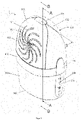
- FIG 1 shows a perspective view of an air dehumidifier 1 according to the invention for the sorption of moisture from room air.
- sorption can be understood to mean absorption as well as adsorption or a combination of absorption and adsorption.
- This consists of several components made of a plastic material.
- the top of the air dehumidifier 1 is formed by a cover 100 .
- the same consists of a cover area 102 and a cover 103 that can be pivoted with respect to the cover area 102.
- said cover 100 consisting of cover 103 and cover area 102, encloses an interior space 101.
- the cover 100 Holding device for a tablet provided, containing a hygroscopic air dehumidifying agent and having an essentially cylindrical tablet body, with a sorption surface provided on two opposite end faces and on a casing side.
- the cover 100 has a large number of ventilation slots 108 in the area of the cover 103 .
- the same are also provided on the opposite side of the device on the cover area 102, the ventilation slots 108 there being a projection of the ventilation slots 108 of the cover 103 in order to provide particularly good ventilation in the sense of a draft possibility through the interior 101.
- the ventilation slots 108 are each arranged like a propeller and open into a ventilation funnel 117 , the neck of which protrudes in the direction of the interior 101 .
- the covering area 102 on the opposite side is designed in the same way.
- the cover 100 is designed in such a way that the end faces of the tablet point in the direction of the ventilation slots 108 of the cover 103 and the cover area 102 by means of said holding device.
- the ventilation slots 108 extend so far away from the ventilation funnel 117 to the outside that the clear width of the ventilation opening, i.e. the distance between two opposite end points of the ventilation slots 108 on the cover area 102 or the cover 103, is at least as large, but preferably larger, than the diameter of a tablet to be used.
- one end face of the tablet is at least in the projection of all ventilation slits 108, but is preferably larger than one end face. Such a configuration enables improved ventilation of the tablet, in particular by a uniform and permanent flow through the cover 100 .
- the lower part of the air dehumidifier 1 forms a collection container 200 enclosing a cavity for a saline solution which is produced by the sorption of moisture from room air via the tablet.
- the collection container 200 has an essentially oval-shaped container base 203 which, as a standing surface for a substrate, contains a peripheral edge on the bottom side and, in particular to increase stability, a curvature starting from the peripheral edge and directed in the direction of the cavity.
- a container wall 203 extends in the direction of the upper part, which is equipped at least on one side with an at least partially transparent or translucent viewing window 205 with a scale 206 in order to provide the user with an opportunity to see the status or the level of the saline solution in the cavity of the collecting container 200 .
- the collection container 200 is connected to the cover 100 via a snap element 204 . Furthermore, a leakage protection 400 is provided between the cover 100 and the collection container 200 , which on the one hand allows the saline solution to flow off the tablet provided in the interior 101 into the cavity of the collection container 200 . On the other hand, however, a leakage of the saline solution from this cavity, resulting from, for example, the air dehumidifier 1 tipping over, is prevented.
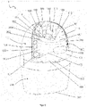
- FIG 2 shows dehumidifier 1 figure 1 in filling position.
- the lid 103 connected to the covering area 102 via hinges 107 has been pivoted about the latter with respect to the covering area 102 and now releases an opening 104 through which, for example, access to the interior 101 can be made possible.
- the opening takes place by means of the opening aid 116 located on the upper side of the cover 103, which provides a possibility of closing the cover 103 with the cover area 102 by means of a snap-on connection means.
- Said opening 104 is delimited by an opening edge 105 of the covering area 102 .
- the cover 103 in turn has a cover edge 106 on. In the closed state of the air dehumidifier 1, the edges 105, 106 rest against one another, so that the interior 101 is closed by the cover 100, apart from the ventilation slots 108.
- the lid 103 also has hanging means in the form of a protruding dome 111 with an essentially hollow-cylindrical basic shape, which is part of the holding device and is used to hold or store a tablet 300 .
- Said tablet 300 has an essentially cylindrical tablet body 301 and consists largely of pressed calcium chloride.
- the edges of the tablet 300 have a bevel 303, in particular to prevent the edges from breaking and/or to make it easier to insert the tablet 300 into the air dehumidifier 1.
- the outer surface of the tablet 300 acts as a sorption surface 302 for sorption of moisture from the room air.
- the tablet 300 also has a central cutout 304 designed as a continuous through-opening or bore that runs coaxially to the cylinder axis and has a larger diameter than the diameter of the dome 111.
- a central cutout 304 designed as a continuous through-opening or bore that runs coaxially to the cylinder axis and has a larger diameter than the diameter of the dome 111.
- the tablet hangs on the mandrel 111 running through the recess 304, so that the hanging means according to the invention and in particular the mandrel 111 allows contact of almost the entire sorption surface 302 with the room air in order to free the sorption surface available for the sorption of moisture 302 of the tablet 300 to enlarge.
- the air dehumidifier 1 can be filled with a tablet 300 in a particularly simple manner.
- the user only has to bring the recess 304 level with the protruding end of the dome 111 and can simply slide the tablet 300 towards the cover 103 or drop it using gravity.
- the mandrel 111 is also equipped with spacer elements in the form of protruding spacer ribs 112 which extend axially and protrude in the radial direction from the outside of the mandrel 111 .
- the spacer ribs 112 are just large enough to enable the tablet 300 to be held securely via the cutout 304 and to allow the inner surface of the tablet 300 to be spaced apart from the outer surface of the mandrel 11 in the area of the cutout 304 . In this way, a defined support option for the tablet 300 that is as small as possible in terms of the contact surface can be provided in the area of its recess 304 in order to minimize the contact surface between the tablet 300 and the mandrel 111 .
- a receptacle 114 protruding from an inner wall 115 of the cover area 102 into the interior 101 is provided.
- the same is designed in such a way that a support or counter bearing for the mandrel 111 can be provided in the closed position in order to ensure a secure holding possibility for the tablet 300 .
- the inner wall 115 is equipped with a large number of reinforcing ribs 109 projecting into the interior 101, so that the covering area 102 and also the cover 103 can only have a small wall thickness, but the air dehumidifier 1 is nevertheless stable.
- spacer elements 110 are provided which protrude into the interior space 101 and are sometimes also formed onto some of the reinforcing ribs 109 .
- the spacer elements 110 are designed as ribs, but can also have other suitable shapes and are used for the defined spacing of a tablet 300 from the inner wall 115 in the closed state of the air dehumidifier 1. In this way it can be prevented that the inner wall 115 areas of the sorption surface 302 the tablet 300 covers, so that there is not enough free sorption surface 302 available for the sorption of moisture from the room air.
- spacer elements 110 protruding from the inner wall 115 in the direction of the interior 101 for clear positioning for example by engaging in the bevel 303 of the tablet or for fixing a tablet 300 in a non-rotatable manner with respect to the dome 111, in particular by using a tablet 300 with a Groove or an opening into which, for example, one of the spacer elements 110 engages.
- the ventilation slots 108 in the closed position can be seen on opposite sides, namely on the covering area 102 and on the opposite side on the lid 103, in order to allow the tablet 300 to be ventilated with room air for sorption of moisture from the room air.
- the mandrel 111 is arranged as a holding device in the closed position of the air dehumidifier 1 between the two opposite areas equipped with ventilation slits 108 in order to provide an opportunity for the room air to flow through the interior 101 of the cover 100 . More precisely, the mandrel 11 is arranged exactly in the mouth of the ventilation funnel 117 of the cover 103, the receptacle 114 in turn in the mouth of the ventilation funnel 117 of the cover area 102.
- the two opposite areas equipped with ventilation slots 108 and the two ventilation funnels 117 are designed in this way that one area is a projection of the other area.
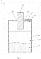
- FIG 3 12 shows a sectional side view of the air dehumidifier 1 through the section line AA figure 1 in closed position.
- the air dehumidifier 1 shown has no tablet 300 in the area of the dome 111 .
- a tablet receptacle 211 is provided on the same bulge 210 in the collection container 200 above the container base 202, which is provided in the middle region by a bulge 210 projecting into the cavity 201.
- a tablet 300 can be stored here, for example to provide the user with a refill option.
- the tablet receptacle 211 can also be used to fix a tablet 300 in the collection container 200 as a transport safeguard.
- the tablet 300 is preferably packed in an outer packaging made of a film material and can be removed from the receptacle 200 before the air dehumidifier 1 is used.
- the tablet 300 which for use—as described above can be slid onto the hanging means designed as a mandrel 111—has the recess 304 for this purpose, which is designed as a funnel 305 at least on one end face of the tablet.
- the tablet 300 has a groove running around the recess but spaced radially. This special shape gives the tablet 300 a larger sorption surface, so that the sorption rate can be improved compared to conventional tablets 300, in particular those equipped with flat end faces.
- the leakage protection 400 is provided between the cover 100 and the collection container.
- the same has fastening sections 401 designed as snap-in elements and is connected to the latter at a mounting section 120 of the cover 100 via the same.
- the assembly section 120 is also used to fasten the collection container 200 to the cover 100 via its snap-on element 204.
- the leakage protection 400 has a large number of guide ribs 402 that can be brought into engagement in the direction of the interior 101 and with the inner wall 115 and protrude, which facilitate the assembly of the leakage protection 400 and the cover 100 facilitate.
- the outlet protection 400 has a peripheral collar 403 with which the outlet protection 400 can be placed on an upper edge 207 of the container wall 203 .
- the leakage protection 400 has a funnel 404 which protrudes into the cavity 201 in some areas.
- the funnel 404 is used to collect the saline solution, which then flows through an upper drain opening 405 into a drain channel 407 and finally through a lower drain opening 406 into the cavity 201 of the collection container 200 .
- the funnel 404 and the discharge channel 407 are designed in such a way, in particular protrude into the cavity and are spaced apart from the container wall 203 in such a way that it is difficult or almost impossible for the saline solution to flow back through the lower discharge opening 406, even if the air dehumidifier 1 tips over .
- the opposite ventilation funnels 117 of the cover area 102 and the cover 103 can be seen in the upper part of the air dehumidifier 1, with the ventilation slots 108 each extending in certain areas into the ventilation funnel 117 in order to improve the ventilation of the interior 101 and thus of the tablet 300 to be arranged there.
- the hollow-cylindrical mandrel 111 extending from the ventilation funnel 117 of the lid 103 in the direction of the receptacle 114 on the ventilation funnel 117 of the covering area 102 also has ventilation slots 113 running in the same direction of extension, in order to ventilate the surface of a suspended tablet 300 in the area of its recess 304 and to thus increasing the free sorption surface area of the tablet 300.
- the spacer ribs 112 which protrude radially from the outer surface of the mandrel 111 and run in said extension direction, serve to minimize the contact surface between the tablet 300 and the mandrel 111.
- the hollow-cylindrical mandrel 111 opens into the in figure 2 pictured and in figure 3 by the tablet 300 concealed receptacle 114, which is also hollow and in turn leads into the ventilation funnel 117 of the cover area 102. It is thus possible for the room air to be drawn through the dehumidifier 1, for example into the ventilation funnel 117 of the cover 103, the hollow cylindrical mandrel 111, the receptacle 114 up to the ventilation funnel 117 of the covering area 102 and in the opposite direction. This ensures particularly good ventilation of the surface of a suspended tablet 300 in the area of its recess 304 . It is thus possible to allow a passage through the cutout 304 of the tablet 300 .
- the lid 103 and the cover area 102 also have the spacer elements 110, which protrude in the direction of the interior 101, in the form of protruding ribs which are molded onto the respective components and define a distance between the tablet 300 and the inner wall 115 in order to avoid the contact surface of the tablet 300 and the cover 100 to keep it as low as possible and to maximize the free sorption surface.
- cams 119 projecting into the interior 101 are provided on some of the spacer elements 110 of the cover 103 . The same are arranged in a circle radially around the mandrel 111 and, when the tablet 300 is inserted, engage in the circumferential groove 306 of the tablet 300 described above.
- cams 119 can make it possible for tablets 300 of different strengths to be picked up and used.
- an illustrated tablet 300 having a groove 306 can be used.
- a smaller tablet 300 can also be used, which only has a thickness that essentially corresponds to the distance between the end of a cam 119 protruding into the interior space 101 and the opposite end of a spacer element 110 of the covering area 102 .
- the same cams 119 can also make it possible to clearly position a tablet 300 and in particular to fix a tablet 300 in a rotationally secure manner with respect to the dome 111 .
- the use of a tablet 300 shown, for example, is suitable for this purpose of the groove 306 has blind holes for receiving the cams 119 in the same area.
- the opening mechanism of the cover 103 can be seen particularly clearly.
- the cover 103 On the upper side of the air dehumidifier 1 , the cover 103 has an opening aid 116 having a hook, as described above, with corresponding connecting means 118 having in particular a hook receptacle being provided on the cover area 102 .
- the hook described can be detached from the hook receptacle of the connecting means 118 in order to pivot the cover 103 with respect to the covering area 102 for changing to a filling position of the air dehumidifier 1.
- FIG 12 shows a partially cut-away perspective view through section line BB of the device figure 1 with inserted tablet.
- figure 4 thus shows an inventive system consisting of dehumidifier 1 and tablet 300.
- the mandrel 111 extends through the recess 304 of the tablet 300.
- the hollow cylindrical mandrel 111 has a smaller diameter than the recess 304.
- the contact between the tablet 300 and the Mandrel 111 is provided via the radially protruding spacer ribs 112, so that in the spaces between two spacer ribs 112 between the lateral surface of the mandrel 111 and the surface of the recess 304 there is a distance to allow the tablet 300 to be ventilated there via the ventilation slots 113 of the mandrel 111 to allow.
- the ventilation slots 113 extend from the mandrel 111 via the ventilation funnel 117 to the front side of the cover 103 and open into some of the ventilation slots 108.
- the ventilation slots 113 are preferably only provided on the sides and on the underside of the mandrel 111, but not on it the top, in order to prevent the saline solution from running out of the aeration funnel 117 in any case.
- the spacer elements 110 formed on the cover 103 and on the same and protruding into the interior 101 in the direction of the tablet 300 are provided, which have the protruding cams 119 in the region of the groove 306 of the tablet 300.
- the moisture absorbed by the tablet 300 drips as a saline solution in the direction of the collection container 200 arranged under the cover 100 and thus into the funnel 404 of the leakage protection 400.
- the saline solution finally reaches the cavity 201 of the collection container 200 through the upper outlet opening 405 via the outlet channel 407 .
- figure 4 also shows the tablet receptacle 211 formed onto the container bottom 202 and protruding into the cavity 201.
- the air dehumidifier 1 is also equipped with a spout.
- the same is provided on the side of the dehumidifier 1, specifically at the level of the outlet protection 400.
- the outlet protection 400 has a spout channel 409 for this purpose, which is open in the direction of the cavity 201 and which at its other end protrudes through an opening in the cover 100 and there opens into a spout opening 408 on the side of the air dehumidifier 1.
- the pouring opening 408 is closed by an openable closure element 209 which is provided on the snap element 204 for fastening the collection container 200 to the cover 100 .
- FIG 5 showed a perspective view of a tablet 300 according to the invention containing a hygroscopic dehumidifying agent for sorption of moisture from room air and having a substantially cylindrical tablet body 301 with an upper side comprising the top surface 307, an underside comprising a bottom surface 308 and a lateral surface 309.
- the outer surface of the Tablet 300 is the sorption surface 302 for sorption of moisture.
- the tablet body 301 has a recess 304 for receiving a spike-shaped hanging means for hanging the tablet 300 on.
- the recess 304 is designed as a continuous cylindrical through-opening or bore, which extends from a top surface 307 through the tablet body 301 to the bottom surface 308 .
- Such a tablet 300 can, for example, in one in the Figures 1 to 4 shown dehumidifier 1 are used.
- the cutout 304 is designed only as a blind hole, a trough, a groove, a gap or some other indentation that enables attachment to a named air dehumidifier 1 .
- the recess 304 widens in the direction of the top surface 307 in the form of a funnel-shaped trough 305 .
- the recess on the opposite side can be designed in the same way.
- At least the top of the tablet 300 is also provided with areas of different levels to increase the available sorption surface area 302 to increase the sorption rate of moisture from room air.
- a groove 306 which is radially offset around the cutout 304 and has a funnel shape in cross section, is provided in the top surface 307 for this purpose.
- the same can additionally or alternatively also be provided exclusively on the underside in the base surface 308 .
- the lateral surface 309 can also have such a configuration.
- varying shapes of the groove 306 or the use of similar means are also conceivable here, in particular a large number of blind holes, a wave shape or other designs that enable the sorption surface 302 to be enlarged.
- said tablet 300 Due to said groove 306 and the funnel-shaped trough 305, said tablet 300 has a wavy shape in the sectional view, in particular on the upper side and/or on the underside.
- the tablet 300 also has a circumferential bevel 303 on the edges of the top surface 307 and the bottom surface 308 in order to simplify the handling of the tablet 300 . It is of course conceivable to use a tablet 300 that does not have a cylindrical basic shape.
- the tablet 300 can also have an oval, a triangular, a polygonal or any cross-section instead of a round one have a designed cross-section suitable for use in a dehumidifier.
- Equipping the essentially cylindrical tablet 300 with a groove 306 in the top surface 307, said chamfers 303 on the top surface 307 and bottom surface 308, the recess 304 with a trough 305 in the top surface 307 allows easier handling and the sorption surface of the tablet 300 can be increased by more than 10% compared to known tablets with pure cylindrical shapes, so that an improved sorption rate can be made possible through the use of a tablet 300 according to the invention.
- the surface area of a tablet 300 according to the invention as shown in the preferred exemplary embodiment, which is available as a sorption surface, including the surface area of the tablet 300 in the area of the recess 304, is preferably in the range from 290 2 to 340 cm 2 .
- figure 6 shows a schematic view of an alternative of an air dehumidifier 1 according to the invention for the sorption of moisture from room air with an inserted tablet 300 containing a hygroscopic air dehumidifier, ie a system according to the invention.
- the dehumidifier 1 comprises a holding device with a hanging means comprising a bearing tip 121 on one side of the tablet 300 and an offset tip 122 opposite, as well as a collecting container 200 arranged below the holding device with a cavity 201 for receiving a hygroscopic solution 212.
- the offset tip 122 is included in a guide element 123, in particular by means of an actuating element, not shown, displaceable in the direction of the tablet 300 and the bearing tip 121 under the preload of a spring 124. The tension of spring 124 pushes the offset tip in the direction of tablet 300.
- the tablet 300 can be suspended between bearing tip 121 and offset tip 122, with only contact between the tablet surface and the two tips 121, 122 mentioned, so that contact is almost the total sorption surface area with room air is allowed to increase the sorption surface area of the tablet 300 that is free and available for the sorption of moisture.
- the tablet 300 can have a recess (not shown) in the area where the tips 121, 122 are accommodated, for example in the form of a blind hole opening or bore, in order to provide the user with a preferred point of application. The fixation can also be improved in this way.
- the pointed design of the bearing tip 121 and the offset tip 122 and the prestressing of the spring 124 when the tablet 300 is suspended result in a slight cutout on both sides of the tablet 300 .
- the tablet 300 dissolves during moisture sorption, its size also decreases.
- a fixation is nevertheless ensured by the displaceable offset tip 122, which is pressed in the direction of the bearing tip 121 by the spring force of the spring 124.
- a tablet 300 used here can also have the grooves described above, funnel-shaped depressions or other configurations that make it possible to increase the sorption surface.
- the tablet 300 can be chamfered or rounded at the edges.
- the air dehumidifier shown can have a cover (not shown) described above and a leak protection shown.
Landscapes
- Chemical & Material Sciences (AREA)
- Engineering & Computer Science (AREA)
- Analytical Chemistry (AREA)
- General Chemical & Material Sciences (AREA)
- Oil, Petroleum & Natural Gas (AREA)
- Chemical Kinetics & Catalysis (AREA)
- Combustion & Propulsion (AREA)
- Mechanical Engineering (AREA)
- General Engineering & Computer Science (AREA)
- Drying Of Gases (AREA)
- Medical Preparation Storing Or Oral Administration Devices (AREA)
- Packages (AREA)
Description
- Die Erfindung betrifft einen Luftentfeuchter oder allgemein eine Vorrichtung zur Sorption von Feuchtigkeit aus Raumluft mittels eines hygroskopischen Luftentfeuchtungsmittels.
- Dergleiche Vorrichtungen sind im Stand der Technik weit verbreitet. Mit Vorrichtungen der bekannten Art wird die Feuchtigkeit aus der Raumluft aufgenommen und in Form von Wasser oder einer wässrigen Lösung in einem Auffangbehälter gesammelt. Hierzu kommt ein hygroskopisches Luftentfeuchtungsmittel zum Einsatz, welches beispielsweise in Pulver- oder Granulatform vorliegt. Als Luftentfeuchtungsmittel haben sich hier insbesondere Calciumchlorid, Magnesiumchlorid, Silicagel oder auch Aluminiumoxidgel als einsetzbar herausgestellt. Beispiele für derartige Vorrichtungen werden insbesondere in der
DE8816583U1 , derEP793060A1 US 5,125,561 offenbart. - Einfacher handhabbar, insbesondere bei dem Befüllen oder Nachfüllen besagter Vorrichtung mit einem Luftentfeuchtungsmittel hat sich jedoch der Einsatz eines Luftentfeuchtungsmittels in Tablettenform erwiesen. Eine derartige Tablette wird dabei insbesondere aus in Pulver- oder Granulatform vorliegenden hygroskopischen Mitteln, wie beispielsweise Calciumchlorid oder Magnesiumchlorid oder einer Mischung, durch ein Pressverfahren hergestellt. Ein Beispiel für eine derartige Vorrichtung zeigt die
EP1779043B1 . Die Oberfläche der Tablette steht dabei für die Sorption der Feuchtigkeit zur Verfügung. Oft werden die Tabletten auf eine Unterlage aufgelegt oder es ist - wie in der genanntenEP177904B1 - Aufgabe der vorliegenden Erfindung ist daher die Bereitstellung einer verbesserten Vorrichtung der eingangs genannten Art.
- Diese Aufgabe wird durch die Merkmale des Anspruchs 1 gelöst.
- Vorteilhafte Weiterbildungen der Erfindung sind mit den Unteransprüchen angegeben.
- Grundgedanke der Erfindung ist die Bereitstellung einer Vorrichtung zur Sorption von Feuchtigkeit aus Raumluft mittels einer Tablette, beinhaltend ein hygroskopisches Luftentfeuchtungsmittel aufweisend einen Tablettenkörper mit einer äußeren Oberfläche - der Sorptionsoberfläche - wobei die Vorrichtung eine Haltevorrichtung für die Tablette aufweist, sowie einen unterhalb der Haltevorrichtung angeordneten Auffangbehälter zur Aufnahme einer Lösung, wobei die Haltevorrichtung ein Hängemittel zum Aufhängen der Tablette oberhalb des Auffangbehälters umfasst, wobei das Hängemittel einen Kontakt nahezu der gesamten Sorptionsoberfläche mit der Raumluft ermöglicht, um die freie und zur Sorption von Feuchtigkeit zur Verfügung stehende Sorptionsoberfläche der Tablette zu vergrößern.
- Ein derartiges Hängemittel kann auf unterschiedliche Art und Weise ausgestaltet sein. Denkbar ist hier die Gestaltung eines vorstehenden Domes, welcher in eine Aussparung der Tablette eingreift, so dass die Tablette an diesem Dorn aufhängbar ist. Auch kann ein Dorn oder ähnlich gestaltetes Hängemittel zum Einsatz kommen, welches sich durch eine Durchgangsöffnung oder Durchgangsloch oder durchgehende Bohrung einer Tablette erstreckt. Ferner kann das Hängemittel durch zwei gegenüberliegende und vorzugsweise im Wesentlichen spitz zulaufende Klemmmittel gestaltet sein, zwischen denen eine Tablette, insbesondere eine zylindrisch gestaltete Tablette an zwei gegenüberliegenden Seiten unter Vorspannung, beispielsweise mittels einer Feder einspannt werden kann. Durch eine bewegliche Anordnung mindestens eines der Klemmmittel und durch geeignete Wahl der Vorspannung kann die Tablette auch bei der Verkleinerung selbiger bei dem Übergang in Lösung durch Bewegung zumindest eines Klemmmittels wirksam gehalten werden.
- Alle Lösungen haben jedoch gemein, dass nahezu die gesamte Sorptionsoberfläche als freie Sorptionsoberfläche zur Verfügung steht, also als Oberfläche des Tablettenkörpers, die für die Sorption der Feuchtigkeit aus der Raumluft zur Verfügung steht. Eine Abdeckung eines Großteils der Oberfläche des Tablettenkörpers kann durch den Einsatz eines derartigen Hängemittels vermieden werden, so dass eine Vergrößerung der freien und zur Sorption von Feuchtigkeit zur Verfügung stehenden Sorptionsoberfläche der Tablette vergrößert wird. Diese vergrößerte freie Sorptionsoberfläche resultiert in einer höheren Sorptionsrate der erfindungsgemäßen Vorrichtung im Vergleich zu herkömmlichen Vorrichtungen der eingangs gezeigten Art.
- Vorzugsweise ist der Auffangbehälter im Wesentlichen als geschlossene Sammelschale gestaltet, um ein Auslaufen der von der sich durch die aufgenommene Feuchtigkeit auflösende Tablette entstehenden Lösung zu verhindern und weist an seiner Oberseite eine angeformte oder als separates Teil gestaltete Deckfläche auf. Dabei ist die Verbindung zwischen Sammelschale und Deckfläche vorzugsweise dicht gestaltet. Zudem weist die Deckfläche vorzugsweise eine Auslaufsperre auf, die es ermöglicht, dass eine Lösung, die von der Deckfläche gesammelt wurde, in die Sammelschale ablaufen kann, und die das Auslaufen der gesammelten Lösung aus einer umgekippten Vorrichtung verhindert. Die Gestaltung insbesondere der Auslaufsperre kann dabei gemäß der Offenbarung der
EP1779043B1 erfolgen, die insoweit die vorliegende Offenbarung ergänzt. - Die zum Einsatz kommende Tablette besteht dabei insbesondere aus hygroskopischen Mitteln in Pulver- oder Granulatform, wie beispielsweise Calciumchlorid oder Magnesiumchlorid oder einer Mischung, durch ein Pressverfahren in besagte Tablettenform gebracht werden. Insbesondere sind die Merkmale einer Tablette sowie ein Herstellungsverfahren einer Tablette denkbar wie in der
EP1426105A1 beschrieben, welche insoweit die vorliegende Offenbarung ergänzt. Die Grundform der Tablette ist vorzugsweise zylindrisch. Denkbar sind jedoch auch eckige Grundform, insbesondere Tabletten mit dreieckigem, viereckigem oder vieleckigem Querschnitt. - Besonders vorteilhaft hat sich ferner eine Gestaltung des Hängemittels der Haltevorrichtung derart erwiesen, dass es dornförmig gestaltet ist, so dass eine Eingriffsmöglichkeit in eine Aussparung einer Tablette zum Aufhängen der Tablette ermöglicht wird. Auch kann das dornförmige Hängemittel derart und insbesondere spitz gestaltet sein, dass es selbst erst bei der Befüllung der Vorrichtung mit einer Tablette eine Aussparung in selbige Tablette einbringt. Insbesondere bei dem Einsatz einer im Wesentlichen zylindrischen Tablette kann selbige jedoch zumindest eine Aussparung, beispielsweise in Form eines einfachen Sackloches, vorzugsweise eines Durchgangsloches oder einer Durchgangsöffnung aufweisen, in die das dornförmige Hängemittel derart eingreift, dass die Tablette hinsichtlich des Auffangbehälters und des Substrates auf dem der Auffangbehälter angeordnet ist, an diesem dornförmigen Hängemittel hängt. So kann im Wesentlichen die gesamte äußere Oberfläche der Tablette - abgesehen von dem Bereich der Aussparung, die mit dem dornförmigen Hängemittel in Kontakt steht - der Tablette als freie Sorptionsoberfläche zur Sorption der Feuchtigkeit aus der Raumluft genutzt werden.
- Die genaue Ausgestaltung des dornförmigen Hängemittels kann dabei von der Gestaltung der Tablette und den übrigen Bauelementen der Vorrichtung sowie der Lage und Anordnung des Hängemittels abhängen. Beispielsweise kann das Hängemittel dornförmig, also vorstehend und im Wesentlichen zylindrisch oder hohlzylindrisch gestaltet sein und sich im Wesentlichen parallel zum Boden des Auffangbehälters und/oder des Substrates erstrecken. Auch ist ein schräger Verlauf denkbar, insbesondere um eine sichere Fixierung der Tablette zu gewährleisten. Weiter kann das Hängemittel hakenförmig ausgebildet sein oder eine andere Form aufweisen, welche ein Aufhängen der Tablette gewährleistet.
- In einer vorteilhaften Weiterentwicklung kann der Dorn zumindest eine Öffnung aufweist, um eine Belüftung der Tablette im Bereich der Aussparung zu ermöglich und um die freie und zur Sorption von Feuchtigkeit zur Verfügung stehende Sorptionsoberfläche der Tablette weiter zu vergrößern. Auch kann die zumindest eine Öffnung derart gestaltet sein, dass sie der durch die Sorption entstehenden Lösung eine bevorzugte Abtropf- und/oder Fließrichtung ermöglicht.
- Weiterhin hat es sich als vorteilhaft herausgestellt, wenn das dornförmige Hängemittel vorstehende Abstandselemente, insbesondere längliche Rippen, die sich in Erstreckungsrichtung des Hängemittels erstrecken können, zur Bereitstellung einer Auflagemöglichkeit für die Tablette im Bereich ihrer Aussparung aufweist, um die Kontaktfläche von Tablette und Hängemittel zu minimieren. In diesem Fall hängt die Tablette demnach lediglich durch eine Auflage von kleinen Oberflächenbereichen innerhalb der Aussparung auf genannten Abstandselementen an dem Hängemittel, so dass die freie Sorptionsoberfläche weiter vergrößert werden kann. Denkbar ist insbesondere auch der Einsatz von Noppen, Vorsprüngen oder Stiften als Abstandselemente.
- Ein weiterer Vorteil ist der Einsatz einer Abdeckung oberhalb des Auffangbehälters, welche einen Innenraum umschließt in dem die Haltevorrichtung oder das Hängemittel vorgesehen ist, wobei die Abdeckung mit zumindest einer Belüftungsöffnung ausgestattet ist, um eine Belüftung der Tablette mit Raumluft zur Sorption der Feuchtigkeit aus der Raumluft zu ermöglichen. Die Abdeckung kann ferner dem Schutz der Tablette dienen und ist daher vorzugsweise im Wesentlichen geschlossen und deckt die Tablette rundum ab. So kann ausgeschlossen werden, dass die Tablette verschmutzt. Die Belüftungsöffnung, vorzugsweise eine Vielzahl an Belüftungsöffnungen sind vorzugsweise zumindest auf dem Niveau der innerhalb des Innenraums angeordneten Tablette, so dass eine gute Belüftung ermöglicht werden kann. Die Belüftungsöffnung kann dabei beliebig gestaltet sein, beispielsweise als Loch, Spalte oder Schlitze. In einer bevorzugten Ausführungsöffnung kommt eine Vielzahl an Belüftungsöffnungen in Form einer Vielzahl von Schlitzen zum Einsatz, welche sich über eine Seite der Abdeckung propellerartig erstrecken. Vorzugsweise liegt die Gesamtöffnungsfläche aller Belüftungsöffnungen im Bereich von 40cm2 bis 80cm2, besonders bevorzugt im Bereich von 45cm2 bis 65cm2.
- Besonders vorteilhaft ist zudem eine Gestaltung der Abdeckung derart, dass zumindest jeweils eine Belüftungsöffnung an einer ersten Seite und an einer der ersten Seite gegenüberliegenden zweiten Seite der Abdeckung vorgesehen ist, wobei zwischen den Belüftungsöffnungen der gegenüberliegenden Seiten innerhalb der Abdeckung die Haltevorrichtung oder das Hängemittel für die Tablette vorgesehen ist, um eine Durchzugsmöglichkeit der Raumluft durch den Innenraum der Abdeckung und insbesondere an der Tablette vorbei bereitzustellen. Bevorzugt kommt hier an zumindest einer, besonders bevorzugt an beiden gegenüberliegenden Seiten eine Vielzahl ab Belüftungsöffnungen zum Einsatz. Vorzugsweise liegt die Öffnungsfläche der Summe der Belüftungsöffnungen einer Seite im Bereich von 20cm2 bis 40cm2. Vorzugsweise entspricht die Oberfläche zumindest einen Belüftungsöffnung der ersten Seite im Wesentlichen der Oberfläche der zumindest einen Belüftungsöffnung der zweiten Seite der Abdeckung. Vorzugsweise liegt die Gesamtöffnungsfläche der Summe der Belüftungsöffnungen beider Seiten im Bereich von 40cm2 bis 80cm2, besonders bevorzugt im Bereich von 45cm2 bis 65cm2.
- Als besonders vorteilhaft hat sich eine Gestaltung derart herausgestellt, dass die zumindest eine Belüftungsöffnung der zweiten Seite eine Projektion der zumindest einen Belüftungsöffnungen der gegenüberliegenden ersten Seite ist. Auf diese Weise kann eine besonders gute Belüftung der Im Innenraum angeordneten Tablette ermöglicht werden, um die Sorption zu verbessern. Vorzugsweise kommt auch hier an beiden Seiten jeweils eine Vielzahl an Belüftungsöffnungen zum Einsatz. Bevorzugt ist zumindest ein Teil der Oberfläche zumindest einer Belüftungsöffnung auf dem Niveau der im Innenraum angeordneten Tablette.
- Ein weiterer Vorteil ist die Unterteilung der Abdeckung in zumindest zwei Bereiche, wobei einer ein Abdeckungsbereich und ein weiterer ein Öffnungsbereich ist, wobei letzterer nach Öffnung desselben einen Eingriff in den Innenraum zur Befüllung der Vorrichtung mit einer Tablette ermöglicht. Vorzugsweise ist die Abdeckung als Baugruppe aus zumindest den besagten Bauteilen zusammengesetzt und sie sind auf beliebige Weise lösbar oder beweglich zueinander verbunden. In einem bevorzugten Ausführungsbeispiel ist der Abdeckungsbereich mit dem Auffangbehälter fest verbunden oder verbindbar und umschließt vorzugsweise einen Großteil des Innenraums. Der Öffnungsbereich ist zur Befüllung der Vorrichtung mit einer Tablette zu öffnen, beispielsweise durch Gestaltung eines Deckels, einer Klappe, eine Schiebetür, einer schubladenartigen Lösung oder eine anderen geeigneten Bauform, welche jeweils eine Öffnung und so dann einen Eingriff in den Innenraum für den Anwender ermöglicht.
- Besonders vorteilhaft hat sich der Einsatz eines Öffnungsbereichs erweisen, der als ein hinsichtlich des Abdeckungsbereichs verschwenkbarer Deckel gestaltet ist. Diese Bauform ist technisch besonders einfach zu realisieren und für den Anwender einfach zu handhaben. Der Abdeckungsbereich ist dabei vorzugsweise fest mit dem Auffangbehälter verbunden oder verbindbar, beispielsweise über geeignete Klemmmittel oder Schnappverbindungsmittel. Vorzugsweise ist zudem zumindest eine Gelenkverbindung, insbesondere ein Scharnier zwischen dem Abdeckungsbereich und dem Deckel vorgesehen. Zudem hat es sich als vorteilhaft herausgestellt, einen Deckel zu verwenden, welcher das Hängemittel umfasst, derart, dass eine Öffnung des Deckels auch zu einer Verschwenkung des Hängemittel hinsichtlich des Abdeckungsbereichs führt, um eine Befüllung der Vorrichtung mit einer Tablette zu erleichtern. Besonders bevorzugt kommt eine derartige Ausgestaltung bei der Verwendung eines dornförmigen Hängemittels zum Einsatz, wobei sich das dornförmige Hängemittel im geschlossenen Zustand des Deckels im Wesentlichen parallel zum Auffangbehälterboden und/oder zum Substrat erstreckt. Bei der Öffnung wird das Hängemittel derart hinsichtlich des Abdeckungsbereichs verschwenkt, dass sich das dornförmige Hängemittel im Wesentlichen rechtwinklig zum Auffangbehälterboden und/oder zum Substrat erstreckt. Auf diese Weise kann eine besonders einfache Befüllmöglichkeit für den Anwender insbesondere unter Nutzungsmöglichkeit der Schwerkraft bereitgestellt werden. Bei dem Einsatz eines das dornförmigen Hängemittel umfassenden Deckels hat es sich ferner als vorteilhaft herausgestellt, selbiges im Bereich oder der Nähe der Schwenkachse des Deckels anzuordnen, um die Standsicherheit der Vorrichtung insbesondere bei eingelegter Tablette zu erhöhen.
- Ein weiterer Vorteil ist die Ausstattung der Abdeckung mit zumindest einem von einer Innenwand der Abdeckung in Richtung Innenraum ragenden Abstandselement, insbesondere in Form einer Rippe oder eines Vorsprungs, um eine definierte Beabstandung einer Tablette von der Innenwand zu ermöglichen. Durch ein derartiges Abstandselement kann beispielsweise verhindert werden, dass die Innenwand der Abdeckung die Sorptionsoberfläche der Tablette ver- oder abdeckt, was zu einer Beeinträchtigung der Sorptionsrate führen könnte.
- Ein weiterer Vorteil ist die Gestaltung des zumindest einen Abstandselementes derart, dass es eine eindeutige Positionierung und insbesondere drehsichere Fixierung einer Tablette hinsichtlich des Hängemittels ermöglicht. Hierbei können beispielsweise mehrere Abstandselemente, vorzugsweise in Form von Rippen zum Einsatz kommen, die unterschiedlich weit in den Innenraum hineinragen. Auf diese Weise kann eine Art Negativform der Tablette durch die Abstandselemente bereitgestellt werden, die ein Abrutschen der Tablette von dem Hängemittel verhindern können. Auch können ein oder mehrere Abstandsmittel derart gestaltet sein, dass sie beispielsweise in Aussparungen, wie etwa Nuten oder Öffnungen oder Bohrungen eingreifen oder selbst einen Eingriff von vorstehenden Bereichen einer Tablette ermöglichen, so dass insbesondere eine drehsichere Fixierung der Tablette ermöglicht werden kann.
- Ferner hat es sich als vorteilhaft herausgestellt, dass mehrere Abstandselemente zum Einsatz kommen, die jeweils unterschiedlich tief oder weit in den Innenraum hineinragen und/oder zumindest ein Abstandselement, welches unterschiedliche tief in den Innenraum ragende Bereiche aufweist, insbesondere um eine Aufnahmemöglichkeit von Tabletten mit unterschiedlichen Stärken und/oder unterschiedlich gestalteten Nuten für die hineinragenden Bereiche der Abstandselemente zu ermöglichen. Ein weiterer Vorteil ist die Ausrüstung der Haltevorrichtung mit einem an einer ersten Seite der Vorrichtung vorgesehenen Befestigungsabschnitt für das Hängemittel, von dem sich das Hängemittel von der ersten Seite der Vorrichtung in Richtung der gegenüberliegenden zweiten Seite erstreckt, wobei die Haltevorrichtung an dieser zweiten Seite eine Aufnahme in Form eines Gegenlagers für das Hängemittel umfasst, wobei das Hängemittel von der Aufnahme lösbar gestaltet ist, um eine einfache Befüllung der Vorrichtung mit einer Tablette aufweisend eine als Durchgangsöffnung, Durchgangsloch oder durchgehenden Bohrung gestaltete Aussparung zu ermöglichen und um eine sichere Fixierung des Hängemittels und somit der Tablette zu gewährleisten. Insbesondere kann eine derartige Bauform in Verbindung mit oben beschriebener zumindest zweiteiliger Abdeckung sinnvoll sein, bei der der Befestigungsabschnitt für das Hängemittel an einem klapp- oder schwenkbaren Deckel vorgesehen werden kann. Eine weitere nicht beanspruchte Ausführungsform ist die Bereitstellung einer Tablette beinhaltend ein hygroskopisches Luftentfeuchtungsmittel zur Sorption von Feuchtigkeit aus Raumluft und aufweisend einen Tablettenkörper mit einer Sorptionsoberfläche, wobei der Tablettenkörper eine Aussparung zur Aufnahme eines dornförmig gestalteten Hängemittels zum Aufhängen der Tablette aufweist. Insbesondere sind die Merkmale einer Tablette sowie ein Herstellungsverfahren einer Tablette denkbar wie in der
EP1426105A1 beschrieben, welche insoweit die vorliegende Offenbarung ergänzt. Besonders vorteilhaft ist dabei der Einsatz einer Tablette, deren Sorptionsoberfläche, also als für die Sorption von Feuchtigkeit aus Raumluft zur Verfügung stehende Oberfläche, inklusive der Oberfläche der Tablette im Bereich der Aussparung eine Größe im Bereich von 2902 bis 340cm2 aufweist. - Ein weiterer Vorteil der nicht beanspruchte Ausführungsform ist die Gestaltung der Aussparung als sich durch den Tablettenkörper erstreckende Durchgangsloch oder Durchgangsöffnung oder Bohrung.
- Ferner kann es in der nicht beanspruchte Ausführungsform als vorteilhaft erweisen, zumindest eine als Sorptionsoberfläche vorgesehene Außenseite des Tablettenkörpers mit Bereichen unterschiedlichen Niveaus auszurüsten, um zur Erhöhung der Sorptionsrate von Feuchtigkeit aus Raumluft die zur Verfügung stehende Sorptionsoberfläche zu vergrößern.
- In einer nicht beanspruchte Ausführungsform weist der Tablettenkörper eine im Wesentlichen zylindrische Grundform einer Oberseite und einer Unterseite auf, wobei die Oberseite und/oder die Unterseite wellenartig gestaltet ist, um zur Erhöhung der Sorptionsrate von Feuchtigkeit aus Raumluft die zur Verfügung stehende Sorptionsoberfläche zu vergrößern.
- Ein weiterer Grundgedanke der vorliegenden Erfindung ist die Bereitstellung eines Systems bestehend aus einer beschriebenen Vorrichtung und einer beschriebenen Tablette.
- Vorzugsweise weist die Vorrichtung dabei eine Abdeckung mit Belüftungsöffnungen auf, wobei die Gesamtöffnungsfläche aller Belüftungsöffnungen vorzugsweise im Bereich von 40cm2 bis 80cm2 liegt, besonders bevorzugt im Bereich von 45cm2 bis 65cm2. Vorzugsweise sind die Belüftungsöffnungen zumindest an zwei gegenüberliegenden Seiten der Abdeckung angeordnet, wobei die Tablette bevorzugt innerhalb der Abdeckung zwischen besagten die Belüftungsöffnungen aufweisenden Bereichen angeordnet ist, um eine Durchzugsmöglichkeit zu ermöglichen.
- Besonders vorteilhaft ist dabei der Einsatz einer Tablette, deren Sorptionsoberfläche, also als für die Sorption von Feuchtigkeit aus Raumluft zur Verfügung stehende Oberfläche, inklusive der Oberfläche der Tablette im Bereich der Aussparung eine Größe im Bereich von 2902 bis 340cm2 aufweist.
- Besonders bevorzugt kommen besagte Belüftungsöffnungen und eine Tablette zum Einsatz, wobei das Oberflächenverhältnis von der Tablettenoberfläche zur Öffnungsoberfläche aller Belüftungsöffnungen im Bereich von 7,25 - 4,25 liegt.
- In einer vorteilhaften Weiterbildung weist die Vorrichtung zusätzlich im Bereich des Auffangbehälters eine Aufnahme für eine weitere Tablette auf, insbesondere um dem Anwender ein System bereitzustellen, welches eine weitere Tablette zur Nachbefüllung der Einheit aufweist, wobei auf Verpackungsmaterial verzichtet werden kann, da als Umverpackung der zweiten Tablette die Vorrichtung selbst zu Anwendung kommt. Auch kann eine derartige Aufnahme im Bereich des Auffangbehälters zur sicheren Verwahrung der zur Anwendung kommenden Tablette im Verkaufsraum zum Einsatz kommen. So kann beispielsweise im Auslieferungszustand der Vorrichtung die mit dem Hängemittel verbindbare Tablette in besagter Aufnahme sicher verwahrt werden.
- In einer vorteilhaften Weiterbildung der Erfindung weist die Vorrichtung mehr als eine Haltevorrichtung für mehrere Tabletten auf. Vorzugsweise sind zwei Haltevorrichtungen für zwei Tabletten vorgesehene, um die Absorptionsrate zu erhöhen. Jede Haltevorrichtung umfasst dabei jeweils ein Hängemittel für eine Tablette. Alternativ kann auch lediglich eine Haltevorrichtung umfassend zwei oder mehr Hängemittel für zwei oder mehr Tabletten. Besagte Hängemittel dienen dabei vorzugsweise wie oberhalb beschrieben zum Aufhängen der Tablette oberhalb des Auffangbehälters, wobei vorzugsweise jedes Hängemittel einen Kontakt nahezu der gesamten Sorptionsoberfläche mit der Raumluft ermöglicht, um die freie und zur Sorption von Feuchtigkeit zur Verfügung stehende Sorptionsoberfläche der Tablette zu vergrößern. Vorzugsweise sind die Haltevorrichtungen und/oder die Hängemittel derart angeordnet, dass alle zur Sorption in der Vorrichtung zur Anwendung kommenden Tabletten beabstandet zueinander angeordnet sind und sich insbesondere nicht berühren. Bevorzugt weisen alle Tabletten eine ähnliche, jedoch voneinander verwetze Position innerhalb oder an der Vorrichtung auf. So kann es beispielsweise beim Einsatz von zwei im Wesentlichen zylinderförmigen Tabletten von Vorteil sein, die Tabletten derart anzuordnen, dass die Deck- und Bodenflächen der Tabletten parallel zueinander angeordnet sind oder besonders bevorzugt in einer Ebene liegen. Vorzugsweise sind die Tabletten in einem solchen Fall derart in der Vorrichtung angeordnet, dass die Deck- und die Bodenflächen benachbart und/oder gegenüberliegende zu Belüftungsöffnungen oder Belüftungsschlitzen der Vorrichtung liegen, um eine besonders gute Sorption zu ermöglichen. Eine derartige Vorrichtung kann auch eine Aufnahmemöglichkeit für mehrere Tabletten im Bereich des Auffangbehälters oder mehrere Aufnahmemöglichkeiten aufweisen.
- Bevorzugte Ausführungsformen von erfindungsgemäßen Vorrichtungen, Tabletten und Systemen werden in den beiliegenden Figuren gezeigt.
-
-
Figur 1 eine perspektivische Ansicht einer erfindungsgemäßen Vorrichtung, -
Figur 2 die Vorrichtung ausFigur 1 in Befüllungsposition, -
Figur 3 eine geschnittene Seitenansicht durch die Schnittlinie A-A der Vorrichtung ausFigur 1 ohne eingelegte Tablette, -
Figur 4 eine teilgeschnittene perspektivische Ansicht durch die Schnittlinie B-B der Vorrichtung ausFigur 1 mit eingelegter Tablette, also ein erfindungsgemäßes Sytem, -
Figur 5 eine perspektivische Ansicht einer erfindungsgemäßen Tablette, -
Figur 6 eine schematische Ansicht einer Alternative einer erfindungsgemäßen Vorrichtung mit eingelegter Tablette, also eines erfindungsgemäßen Systems. -
Figur 1 zeigt eine perspektivische Ansicht eines erfindungsgemäßen Luftentfeuchters 1 zur Sorption von Feuchtigkeit aus Raumluft. Dabei kann unter Sorption sowohl eine Absorption, als auch eine Adsorption oder auch eine Kombination von Ab- und Adsorption verstanden werden. Dieser setzt sich aus mehreren aus einem Kunststoffmaterial gefertigten Bauelementen zusammen. Das Oberteil des Luftentfeuchters 1 wird durch eine Abdeckung 100 gebildet. Selbige setzt sich zusammen aus einem Abdeckbereich 102 und einem hinsichtlich des Abdeckbereichs 102 verschwenkbaren Deckel 103. Im abgebildeten verschlossenen Zustand des Luftentfeuchters 1 umschließt besagte aus Deckel 103 und Abdeckbereich 102 bestehende Abdeckung 100 einen Innenraum 101. Im Innenraum 101 ist eine von der Abdeckung 100 verdeckte Haltevorrichtung für eine Tablette vorgesehen, beinhaltend ein hygroskopisches Luftentfeuchtungsmittel und aufweisend einen im wesentlichen zylindrischen Tablettenkörper, mit einer an zwei gegenüberliegenden Stirnseite sowie einer Mantelseite vorgesehenen Sorptionsoberfläche. Um eine Sorption der Feuchtigkeit zu ermöglichen, weist die Abdeckung 100 im Bereich des Deckels 103 eine Vielzahl von Belüftungsschlitzen 108 auf. Selbige sind auch auf der gegenüberliegenden Seite der Vorrichtung auf dem Abdeckbereich 102 vorgesehen, wobei die Belüftungsschlitze 108 dort eine Projektion der Belüftungsschlitze 108 des Deckels 103 sind, um eine besonders gute Belüftung im Sinne einer Durchzugsmöglichkeit durch den Innenraum 101 bereitzustellen. Die Belüftungsschlitze 108 sind jeweils propellerartig angeordnet und münden in einem Belüftungstrichter 117, wobei dessen Hals in Richtung Innenraum 101 hineinragt. Auf selbige Weise ist der Abdeckbereich 102 auf der gegenüberliegenden Seite gestaltet. Dabei ist die Abdeckung 100 derart gestaltet, dass die Stirnseiten der Tablette mittels besagter Haltevorrichtung in Richtung der Belüftungsschlitze 108 des Deckels 103 und des Abdeckbereichs 102 weisen. Die Belüftungsschlitze 108 erstrecken sich so weit von dem Belüftungstrichtern 117 nach außen weg, dass die lichte Weite der Belüftungsöffnung, also der Abstand zwischen zwei auf dem Abdeckbereich 102 oder dem Deckel 103 gegenüberliegenden Endpunkten der Belüftungsschlitze 108 zumindest so groß ist, bevorzugt jedoch größer ist, als der Durchmesser einer zum Einsatz kommenden Tablette. Aufgrund der propellerartigen Anordnung der Belüftungsschlitze 108 liegt die jeweils eine Stirnseite der Tablette also zumindest in der Projektion aller Belüftungsschlitze 108, vorzugsweise ist selbige jedoch größer als eine Stirnseite. Durch eine derartige Gestaltung kann eine verbesserte Belüftung der Tablette, insbesondere durch eine gleichmäßige und dauerhafte Durchströmung der Abdeckung 100 ermöglicht werden. - Das Unterteil des Luftentfeuchters 1 bildet ein Auffangbehälter 200 umschließend einen Hohlraum für eine Salzlösung, welche durch die Sorption von Feuchtigkeit aus Raumluft über die Tablette entsteht. Der Auffangbehälter 200 weist einen im Wesentlichen oval geformten Behälterboden 203 auf, der als Standfläche für ein Substrat einen bodenseitig umlaufenden Rand beinhaltet sowie insbesondere zur Erhöhung der Stabilität eine vom umlaufenden Rand ausgehende und in Richtung Hohlraum gerichtete Wölbung. In Richtung Oberteil erstreckt sich eine Behälterwand 203, welche zumindest auf einer Seite mit einem zumindest teilweise transparenten oder durchscheinenden Sichtfenster 205 mit einer Skala 206 ausgestattet ist, um dem Anwender eine Möglichkeit bereitzustellen, den Stand oder das Niveau der Salzlösung im Hohlraum des Auffangbehälters 200 einzusehen. Der Auffangbehälter 200 ist über ein Schnappelement 204 mit der Abdeckung 100 verbunden. Ferner ist zwischen Abdeckung 100 und Auffangbehälter 200 ein Auslaufschutz 400 vorgesehen, der einerseits ein Abfließen der Salzlösung von der im Innenraum 101 vorgesehenen Tablette in den Hohlraum des Auffangbehälters 200 ermöglicht. Auf der anderen Seite jedoch ein aus beispielsweise dem Umkippen des Luftentfeuchters 1 resultierendes Auslaufen der Salzlösung aus diesem Hohlraum verhindert.
-
Figur 2 zeigt den Luftenfeuchter 1 ausFigur 1 in Befüllungsposition. Hierzu ist der mit dem Abdeckbereich 102 über Scharniere 107 verbundene Deckel 103 um letztere hinsichtlich des Abdeckbereichs 102 verschwenkt worden und gibt nun eine Öffnung 104 frei durch die beispielsweise ein Eingriff in den Innenraum 101 ermöglicht werden kann. Das Öffnen erfolgt mittels der an der Oberseite des Deckels 103 gelegenen Öffnungshilfe 116, welche eine Verschlussmöglichkeit über ein Schnappverbindungsmittel des Deckels 103 mit dem Abdeckbereich 102 bereitstellt. Besagte Öffnung 104 wird durch eine Öffnungskante 105 des Abdeckbereichs 102 begrenzt. Der Deckel 103 wiederum weist eine Deckelkante 106 auf. Im geschlossenen Zustand des Luftentfeuchters 1 liegen die Kanten 105, 106 aneinander an, so dass der Innenraum 101 durch die Abdeckung 100, abgesehen von den Belüftungsschlitzen 108, geschlossen ist. - Der Deckel 103 weist ferner ein Hängemittel in Form eines vorstehenden Doms 111 mit einer im Wesentlichen hohlzylindrischen Grundform auf, welcher Teil der Haltevorrichtung ist und zum Halten oder zur Lagerung einer Tablette 300 dient. Besagte Tablette 300 weist einen im Wesentlichen zylindrisch gestalteten Tablettenkörper 301 auf und besteht zu einem Großteil aus gepresstem Calciumchlorid. Die Kanten der Tablette 300 weisen eine Fase 303 auf, insbesondere um ein Brechen der Kanten zur vermeiden und/oder um ein Einsetzen der Tablette 300 in den Luftentfeuchter 1 zu erleichtern. Die äußere Oberfläche der Tablette 300 fungiert als Sorptionsoberfläche 302 für die Sorption der Feuchtigkeit aus der Raumluft. Die Tablette 300 weist ferner eine als durchgehende und koaxial zur Zylinderachse verlaufende Durchgangsöffnung oder Bohrung gestaltete zentrische Aussparung 304 auf, welche einen größeren Durchmesser aufweist, als der Durchmesser des Domes 111. Selbige dient durch die Bereitstellung einer Aufnahmemöglichkeit des Domes 111 der Aufhängung der Tablette 300 im Innenraum 101 des Luftentfeuchters 1. Da der Dorn 111 mit dem Deckel 103 über einen Befestigungsabschnitt, im vorliegenden Fall durch Anformung an den Belüftungstrichter 117 verbunden ist, geht ein Verschwenken des Deckels 103 in die geschlossene Position einher mit einem Verschwenken des Domes 111 und somit auch der Tablette 300. In der geschlossenen Position verläuft die Achse des Doms 111 im Wesentlichen parallel zum Behälterboden 202 und/oder zum Substrat. In dieser Position hängt die Tablette an dem durch die Aussparung 304 verlaufenden Dorn 111, so dass das erfindungsgemäße Hängemittel und insbesondere der Dorn 111 einen Kontakt nahezu der gesamten Sorptionsoberfläche 302 mit der Raumluft ermöglicht, um die freie und zur Sorption von Feuchtigkeit zur Verfügung stehende Sorptionsoberfläche 302 der Tablette 300 zu vergrößern.
- In der gezeigten Befüllungsposition, bei der die Achse des Domes 111 im Wesentlichen orthogonal zum Behälterboden 202 und/oder zum Substrat verläuft, ist eine Befüllung des Luftentfeuchters 1 mit einer Tablette 300 besonders einfach möglich. Der Anwender muss lediglich die Aussparung 304 in Höhe des vorstehenden Endes des Domes 111 bringen und kann die Tablette 300 und Ausnutzung der Schwerkraft einfach in Richtung Deckel 103 gleiten oder fallen lassen.
- Der Dorn 111 ist ferner mit sich axial erstreckenden und in radiale Richtung von der Außenseite des Domes 111 hervorstehenden Abstandselementen in Form von vorstehenden Abstandsrippen 112 ausgestattet. Die Abstandsrippen 112 sind genau so groß, dass ein sicherer Halt der Tablette 300 über die Aussparung 304 ermöglicht werden kann und dass eine Beabstandung der inneren Oberfläche der Tablette 300 im Bereich der Aussparung 304 von der äußeren Manteloberfläche des Domes 11 ermöglicht wird. So kann eine definierte und hinsichtlich der Kontaktfläche möglichst kleine Auflagemöglichkeit für die Tablette 300 im Bereich ihrer Aussparung 304 bereitgestellt werden, um die Kontaktfläche zwischen Tablette 300 und Dorn 111 zu minimieren.
- Auf der dem Deckel 103 gegenüberliegenden Seite ist im Bereich des Belüftungstrichters 117 eine von einer Innenwand 115 des Abdeckbereichs 102 in den Innraum 101 vorstehende Aufnahme 114 vorgesehen. Selbige ist derart gestaltet, dass eine Auflagemöglichkeit oder ein Gegenlager für den Dorn 111 in der geschlossenen Position bereitgestellt werden kann, um eine sichere Haltemöglichkeit für die Tablette 300 zu gewährleisten. Ferner ist die Innenwand 115 mit einer Vielzahl von in den Innenraum 101 ragenden Verstärkungsrippen 109 ausgestattet, so dass der Abdeckbereich 102 und auch der Deckel 103 lediglich eine geringe Wandstärke aufweisen können, der Luftentfeuchter 1 jedoch dennoch stabil ist. Zudem sind mehrere in den Innenraum 101 ragende Abstandselemente 110 vorgesehen, die mitunter auch an einige der Verstärkungsrippen 109 angeformt sind. Die Abstandselemente 110 sind als Rippen ausgestaltet, können jedoch auch andere sich eignende Formen aufweisen und dienen der definierten Beabstandung einer Tablette 300 von der Innenwand 115 im geschlossenen Zustand des Luftenfeuchters 1. Auf diese Weise kann verhindert werden, dass die Innenwand 115 Bereiche der Sorptionsoberfläche 302 der Tablette 300 abdeckt, so dass nicht ausreichend freie Sorptionsoberfläche 302 für die Sorption der Feuchtigkeit aus der Raumluft zur Verfügung steht. Denkbar ist zudem die Nutzung der von der Innenwand 115 in Richtung Innenraum 101 ragenden Abstandselemente 110 zur eindeutigen Positionierung, beispielsweise mittels Eingriff in die Fase 303 der Tablette oder zur drehsichern Fixierung einer Tablette 300 hinsichtlich des Domes 111, insbesondere durch Verwendung einer Tablette 300 mit einer Nut oder einer Öffnung, in die beispielsweise eines der Abstandselemente 110 eingreift.
- Ferner sind in
Figur 2 die Belüftungsschlitze 108 in geschlossener Position an gegenüberliegenden Seiten, nämlich an dem Abdeckbereich 102 und gegenüberliegend an dem Deckel 103 zu erkennen, um eine Belüftung der Tablette 300 mit Raumluft zur Sorption der Feuchtigkeit aus der Raumluft zu ermöglichen. Der Dorn 111 ist als Haltevorrichtung dabei in geschlossener Position des Luftentfeuchters 1 zwischen beiden einander gegenüberliegenden und mit Belüftungsschlitzen 108 ausgestatteten Bereichen angeordnet, um eine Durchzugsmöglichkeit der Raumluft durch den Innenraum 101 der Abdeckung 100 bereitzustellen. Genauer gesagt ist der Dorn 11 genau in der Mündung des Belüftungstrichters 117 des Deckels 103 angeordnet, die Aufnahme 114 wiederum in der Mündung des Belüftungstrichters 117 des Abdeckbereichs 102. Dabei sind die beiden gegenüberliegenden und mit Belüftungsschlitzen 108 ausgestatteten Bereiche sowie die beiden Belüftungstrichter 117 derart gestaltet, dass der eine Bereich eine Projektion des anderen Bereichs ist. -
Figur 3 zeigt eine geschnittene Seitenansicht durch die Schnittlinie A-A des Luftentfeuchters 1 ausFigur 1 in geschlossener Position. Der besseren Übersicht halber weist der gezeigte Luftenfeuchter 1 im Bereich des Domes 111 keine Tablette 300 auf. Jedoch ist im Auffangbehälter 200 oberhalb des Behälterbodens 202, der im Mittelbereich durch eine in den Hohlraum 201 ragende Wölbung 210 bereitgestellt wird, auf selbiger Wölbung 210 eine Tablettenaufnahme 211 vorgesehen. Hier kann eine Tablette 300 verwahrt werden, beispielsweise um dem Anwender eine Nachfüllmöglichkeit bereitzustellen. Ach kann die Tablettenaufnahme 211 zur Fixierung einer Tablette 300 im Auffangbehälter 200 als Transportsicherung dienen. Die Tablette 300 ist vorzugsweise in einer Umverpackung aus einem Folienmaterial verpackt und ist vor der Nutzung des Luftentfeuchters 1 aus dem Aufnahmebehälter 200 zu entnehmen. Die Tablette 300, die zur Nutzung - wie oberhalb beschrieben auf das als Dorn 111 gestaltete Hängemittel geschoben werden kann - weist hierfür die Aussparung 304 auf, welche zumindest auf einer Stirnseite der Tablette als Trichter 305 gestaltet ist. Zudem weist die Tablette 300 eine um die Aussparung herum verlaufende, jedoch radial beabstandete Nut auf. Diese besondere Form verleiht der Tablette 300 eine größere Sorptionsoberfläche, so dass die Sorptionsrate im Vergleich zu herkömmlichen, insbesondere mit flachen Stirnflächen ausgestatteten Tabletten 300 verbessert werden kann. - Zwischen der Abdeckung 100 und dem Auffangbehälter ist -wie oberhalb angesprochen - der Auslaufschutz 400 vorgesehen. Selbiger weist als Schnappelemente gestaltete Befestigungsabschnitte 401 auf und ist über selbige an einem Montageabschnitt 120 der Abdeckung 100 mit letztgenannter verbunden. Der Montageabschnitt 120 dient auch der Befestigung des Auffangbehälters 200 über dessen Schnappelement 204 an der Abdeckung 100. Zudem weist der Auslaufschutz 400 eine Vielzahl von in Richtung Innenraum 101 sowie mit der Innenwand 115 in Eingriff bringbare und vorstehende Führungsrippen 402 auf, die eine Montage des Auslaufschutzes 400 and der Abdeckung 100 erleichtern. Zur Befestigung des Auslaufschutzes 400 and dem Auffangbehälter 200 weist der Auslaufschutz 400 einen umlaufenden Kragen 403 auf, mit welchem der Auslaufschutz 400 auf eine obere Kante 207 der Behälterwand 203 aufgesetzt werden kann. Dabei sind beide Bereiche derart gestaltet, dass eine dichte Verbindung bereitgestellt werden kann. Denkbar ist hier auch der Einsatz einer optionalen Dichtung, um die Abdichtung weiter zu verbessern. Der Auslaufschutz 400 weist einen Trichter 404 auf, welche bereichsweise in den Hohlraum 201 ragt. Der Trichter 404 dient der Sammlung der Salzlösung, welche daraufhin durch eine obere Ablauföffnung 405 in einen Ablaufkanal 407 und schließlich durch eine untere Ablauföffnung 406 in den Hohlraum 201 des Auffangbehälters 200 fließt. Dabei sind der Trichter 404 sowie der Ablaufkanal 407 derart konstruiert, ragen insbesondere derart in den Hohlraum hinein und sind derart von der Behälterwand 203 beabstandet, dass ein Zurücklaufen der Salzlösung selbst bei einem Umkippen des Luftentfeuchters 1 durch die untere Auslauföffnung 406 erschwert oder nahezu unmöglich wird.
- Im oberen Teil des Luftentfeuchters 1 sind die gegenüberliegenden Belüftungstrichter 117 des Abdeckbereichs 102 und des Deckels 103 zu erkennen, wobei sich die Belüftungsschlitze 108 jeweils bereichsweise in den Belüftungstrichter 117 erstrecken, um die Belüftung des Innenraumes 101 und somit der dort anzuordnenden Tablette 300 zu verbessern. Der sich von dem Belüftungstrichter 117 des Deckels 103 in Richtung der Aufnahme 114 am Belüftungstrichter 117 des Abdeckbereichs 102 erstreckende hohlzylindrische Dorn 111 weist zudem in selbige Erstreckungsrichtung verlaufende Belüftungsschlitze 113 auf, um die Oberfläche einer eingehängten Tablette 300 im Bereich ihrer Aussparung 304 zu belüften und um somit die freie Sorptionsoberfläche der Tablette 300 zu vergrößern. Die radial von der äußeren Oberfläche des Domes 111 vorstehende und in besagte Erstreckungsrichtung verlaufende Abstandsrippen 112 dienen der Minimierung der Kontaktfläche zwischen Tablette 300 und Dorn 111. Der hohlzylindrische Dorn 111 mündet in der in
Figur 2 abgebildeten und inFigur 3 durch die Tablette 300 verdeckten Aufnahme 114, welche ebenfalls hohl gestaltet ist und wiederum in den Belüftungstrichter 117 des Abdeckbereichs 102 führt. Somit kann eine Durchzugsmöglichkeit für die Raumluft durch den Luftentfeuchters 1 ermöglicht werden, beispielsweise in den Belüftungstrichter 117 des Deckels 103, den hohlzylindrischen Dorn 111, die Aufnahme 114 bis hin zum Belüftungstrichter 117 des Abdeckbereichs 102 und in entgegengesetzte Richtung. Hierdurch wird eine besondere gute Belüftung der Oberfläche einer eingehängten Tablette 300 im Bereich ihrer Aussparung 304 gewährleistet. Es kann somit eine Durchzugsmöglichkeit durch die Aussparung 304 der Tablette 300 ermöglicht werden. - Der Deckel 103 sowie der Abdeckbereich 102 weisen zudem die in Richtung Innenraum 101 ragenden Abstandselemente 110 in Form von vorstehenden, an die jeweiligen Bauteile angeformten Rippen auf, die einen Abstand zwischen Tablette 300 und Innenwand 115 definieren, um die Kontaktfläche von Tablette 300 und Abdeckung 100 möglichst gering zu halten und um die freie Sorptionsoberfläche zu maximieren. Zudem sind an einigen der Abstandselemente 110 des Deckels 103 in den Innenraum 101 ragende Nocken 119 vorgesehen. Selbige sind auf einem Kreis radial um den Dorn 111 herum angeordnet und greifen bei eingelegter Tablette 300 in die oberhalb beschriebene umlaufende Nut 306 der Tablette 300 ein. Insbesondere kann durch diese Nocken 119 ermöglicht werden, dass Tabletten 300 unterschiedlicher Stärke aufgenommen und genutzt werden können. Zum einen kann eine abgebildete Tablette 300 mit einer Nut 306 verwendet werden. Zum anderen kann jedoch auch eine kleinere Tablette 300 zum Einsatz kommen, die lediglich eine Stärke derart aufweist, die im Wesentlichen dem Abstand zwischen dem in den Innenraum 101 ragenden Ende einer Nocke 119 und dem gegenüberliegenden Ende eines Abstandselementes 110 des Abdeckbereiches 102 entspricht. Auch kann durch selbige Nocken 119 eine Möglichkeit einer eindeutigen Positionierung einer Tablette 300 und insbesondere einer drehsicheren Fixierung einer Tablette 300 hinsichtlich des Domes 111 ermöglicht werden. Hierzu eignet sich beispielsweise der Einsatz einer gezeigten Tablette 300, die jedoch beispielsweise anstelle der Nut 306 im selben Bereich Sacklöcher zur Aufnahme der Nocken 119 aufweist.
- Auch ist in
Figur 3 besonders deutlich der Öffnungsmechanismus des Deckels 103 zu erkennen. An der Oberseite des Luftentfeuchters 1 weist der Deckel 103 wir oberhalb beschrieben eine Öffnungshilfe 116 aufweisend einen Haken auf, wobei korrespondierende Verbindungsmittel 118 aufweisend insbesondere eine Hakenaufnahme an dem Abdeckbereich 102 vorgesehen sind. Durch leichten Druck von oben auf die Öffnungshilfe 116 kann beschriebener Haken aus der Hakenaufnahme des Verbindungsmittels 118 ausgehängt werden, um den Deckel 103 für einen Wechsel in eine Befüllungsposition des Luftentfeuchters 1 hinsichtlich des Abdeckbereichs 102 zu verschwenken. -
Figur 4 zeigt eine teilgeschnittene perspektivische Ansicht durch die Schnittlinie B-B der Vorrichtung ausFigur 1 mit eingelegter Tablette.Figur 4 zeigt somit ein erfindungsgemäßes System bestehend aus Luftenfeuchter 1 und Tablette 300. Der Dorn 111 erstreckt sich durch die Aussparung 304 der Tablette 300. Der hohlzylindrische Dorn 111 weist jedoch einen kleinen Durchmesser auf, als die Aussparung 304. Der Kontakt zwischen der Tablette 300 und dem Dorn 111 wird über die radial vorstehenden Abstandsrippen 112 bereitgestellt, so dass in den Zwischenräumen zwischen zwei Abstandsrippen 112 zwischen der Mantelfläche des Domes 111 und der Oberfläche der Aussparung 304 ein Abstand vorgesehen ist, um dort eine Belüftungsmöglichkeit der Tablette 300 über die Belüftungsschlitze 113 des Domes 111 zu ermöglichen. Die Belüftungsschlitze 113 erstrecken sich dabei von dem Dorn 111 über den Belüftungstrichter 117 bis in die Frontseite des Deckels 103 und münden in einigen der Belüftungsschlitze 108. Bevorzugt sind die Belüftungsschlitze 113 nur an den Seiten sowie an der Unterseite des Domes 111 vorgesehen, nicht jedoch an der Oberseite, um ein herauslaufen der Salzlösung aus dem Belüftungstrichter 117 in jedem Fall zu vermeiden. - Zur Fixierung der Tablette 300 innerhalb des Innenraums 101 sind die an den Deckel 103 und an selbigen angeformte und in den Innenraum 101 in Richtung Tablette 300 ragende Abstandselemente 110 vorgesehen, welche im Bereich der Nut 306 der Tablette 300 die vorstehenden Nocken 119 aufweisen. Die von der Tablette 300 sorbierte Feuchtigkeit tropft als Salzlösung in Richtung des unter der Abdeckung 100 angeordneten Auffangbehälters 200 und somit in den Trichter 404 des Auslaufschutzes 400. Durch die obere Auslauföffnung 405 gelangt die Salzlösung schließlich über den Auslaufkanal 407 in den Hohlraum 201 des Auffangbehälters 200.
Figur 4 zeigt auch noch einmal die an den Behälterboden 202 angeformte und in den Hohlraum 201 ragende Tablettenaufnahme 211. - Zum Entleeren des Hohlraumes 201 des Auffangbehälters 201 ist der Luftentfeuchter 1 zudem mit einem Ausguss ausgestattet. Selbiger ist seitlich an dem Luftentfeuchter 1 vorgesehen und zwar auf der Höhe des Auslaufschutzes 400. Der Auslaufschutz 400 weist hierfür einen Ausgusskanal 409 auf, der in Richtung des Hohlraumes 201 offen ist und welcher an seinem anderen Ende durch eine Öffnung der Abdeckung 100 ragt und dort in einer Ausgussöffnung 408 an der Seite des Luftentfeuchters 1 mündet. Verschlossen wird die Ausgussöffnung 408 von einem öffenbaren Verschlusselement 209, welches an dem Schnappelement 204 zur Befestigung des Auffangbehälters 200 an der Abdeckung 100 vorgesehen ist.
-
Figur 5 zeigte eine perspektivische Ansicht einer erfindungsgemäßen Tablette 300 beinhaltend ein hygroskopisches Luftentfeuchtungsmittel zur Sorption von Feuchtigkeit aus Raumluft und aufweisend einen im Wesentlichen zylindrischen Tablettenkörper 301 mit einer Oberseite umfassend die Deckfläche 307, einer Unterseite, umfassend eine Bodenfläche 308 sowie einer Mantelfläche 309. Die äußere Oberfläche der Tablette 300 ist die Sorptionsoberfläche 302 zur Sorption der Feuchtigkeit. Der Tablettenkörper 301 weist eine Aussparung 304 zur Aufnahme eines dornförmig gestalteten Hängemittels zum Aufhängen der Tablette 300 auf. Im gezeigten Ausführungsbeispiel ist die Aussparung 304 als durchgehende zylindrische Durchgangsöffnung oder Bohrung gestaltet, die von einer Deckfläche 307 durch den Tablettenkörper 301 bis zur Bodenfläche 308 reicht. Eine derartige Tablette 300 kann beispielsweise in einem in denFiguren 1 bis 4 gezeigten Luftentfeuchter 1 zum Einsatz kommen. Es ist jedoch alternativ denkbar, dass die Aussparung 304 nur als ein Sackloch, eine Mulde, eine Nut, eine Spalte oder eine anderweitige Vertiefung ausgebildet ist, die eine Befestigung an einem genannten Luftentfeuchter 1 ermöglicht. Auch Durchgangsöffnungen oder Löcher anderer Art, insbesondere mit einem anderen Querschnitt sind denkbar. Die Aussparung 304 ist in Richtung Deckfläche 307 in Form einer trichterförmigen Mulde 305 geweitet. Auf gleiche Weise kann die Aussparung auf der gegenüberliegenden Seite gestaltet sein. Zumindest die Oberseite der Tablette 300 ist zudem mit Bereichen unterschiedlichen Niveaus ausgestattet, um zur Erhöhung der Sorptionsrate von Feuchtigkeit aus Raumluft die zur Verfügung stehende Sorptionsoberfläche 302 zu vergrößern. Im vorliegenden Ausführungsbeispiel ist hierfür eine um die Aussparung 304 radial versetzt herumlaufende und im Querschnitt trichterförmige Nut 306 in der Deckfläche 307 vorgesehen. Selbige kann in einer Variante zusätzlich oder alternativ auch ausschließlich auf der Unterseite in der Bodenfläche 308 vorgesehen werden. Auch kann die Mantelfläche 309 eine derartige Gestaltung aufweisen. Selbstverständlich sind hier auch variierende Formen der Nut 306 oder der Einsatz ähnlicher Mittel denkbar, insbesondere eine Vielzahl von Sacklöchern, eine Wellenform oder andere Ausführungen, die eine Vergrößerung der Sorptionsoberfläche 302 ermöglichen. Durch besagte Nut 306 und die trichterförmige Mulde 305 weist besagte Tablette 300 in der Schnittansicht insbesondere an der Oberseite und/oder an der Unterseite eine wellenartige Gestaltung auf. Auch weist die Tablette 300 an den Kanten der Deckfläche 307 und der Bodenfläche 308 jeweils eine umlaufende Fase 303 auf, um die Handhabung der Tablette 300 zu vereinfachen. Natürlich ist es denkbar eine Tablette 300 einzusetzen, welche keine zylindrische Grundform aufweist. Die Tablette 300 kann auch anstelle eines runden Querschnittes einen ovalen, einen dreieckigen, einen vieleckigen oder einen beliebig gestalteten Querschnitt aufweisen, der sich zum Einsatz in einem Luftentfeuchter eignet. - Durch die Ausstattung der im Wesentlichen zylindrischen Tablette 300 mit einer Nut 306 in der Deckfläche 307, besagten Fasen 303 an Deckfläche 307 und Bodenfläche 308, der Aussparung 304 mit einer Mulde 305 im Bereich der Deckfläche 307 kann eine einfachere Handhabung ermöglicht und die Sorptionsoberfläche der Tablette 300 im Vergleich zur bekannten Tabletten mit reinen Zylinderformen um über 10% gesteigert werden, so dass eine verbesserte Sorptionsrate durch den Einsatz einer erfindungsgemäßen Tablette 300 ermöglicht werden kann. Die Oberfläche einer erfindungsgemäßen Tablette 300, wie sie im bevorzugten Ausführungsbeispiel gezeigt ist, die als Sorptionsoberfläche zur Verfügung steht, liegt inklusive der Oberfläche der Tablette 300 im Bereich der Aussparung 304 vorzugsweise im Bereich von 2902 bis 340cm2.
-
Figur 6 zeigt eine schematische Ansicht einer Alternative eines erfindungsgemäßen Luftentfeuchters 1 zur Sorption von Feuchtigkeit aus Raumluft mit eingelegter Tablette 300 beinhaltend ein hygroskopisches Luftentfeuchtungsmittel, also eines erfindungsgemäßen Systems. - Der Luftenfeuchter 1 umfasst eine Haltevorrichtung mit einem Hängemittel umfassend eine Lagerspitze 121 an der einen Seite der Tablette 300 und eine gegenüberliegende Versatzspitze 122, sowie einen unterhalb der Haltevorrichtung angeordneten Auffangbehälter 200 mit einem Hohlraum 201 zur Aufnahme einer hygroskopischen Lösung 212. Die Versatzspitze 122 ist dabei in einem Führungselement 123, insbesondere mittels eines nicht dargestellten Betätigungselementes verschiebbar in Richtung der Tablette 300 sowie der Lagerspitze 121 unter Vorspannung einer Feder 124 gelagert. Die Spannung der Feder 124 drückt die Versatzspitze dabei in Richtung Tablette 300. Hierdurch kann die Tablette 300 zwischen Lagerspitze 121 und Versatzspitze 122 aufgehängt werden, wobei lediglich ein Kontakt zwischen der Tablettenoberfläche und den beiden genannten Spitzen 121, 122 vorliegt, so dass einen Kontakt nahezu der gesamten Sorptionsoberfläche mit der Raumluft ermöglicht wird, um die freie und zur Sorption von Feuchtigkeit zur Verfügung stehende Sorptionsoberfläche der Tablette 300 zu vergrößern. Ferner kann die Tablette 300 im Bereich der Aufnahme der Spitzen 121, 122 eine nicht gezeigte Aussparung, beispielsweise in Form einer Sacklochöffnung oder -bohrung aufweisen, um dem Anwender einen bevorzugten Angriffspunkt bereitzustellen. Auch kann so die Fixierung verbessert werden. Im gezeigten Fall wird durch die spitze Gestaltung der Lagerspitze 121 und der Versatzspitze 122 sowie aufgrund der Vorspannung der Feder 124 beim Aufhängen der Tablette 300 eine geringfügige Aussparung auf beiden Seiten der Tablette 300 eingebracht. Im Zuge der Auflösung der Tablette 300 bei der Sorption der Feuchtigkeit verkleinert sich auch ihre Größe. Eine Fixierung ist jedoch dennoch durch die verschiebbare Versatzspitze 122 gewährleistet, die durch die Federkraft der Feder 124 in Richtung der Lagerspitze 121 gedrückt wird. Selbstverständlich kann eine hier eingesetzte Tablette 300 auch oberhalb beschriebene Nuten, trichterförmige Mulden oder andere Gestaltungen aufweisen, die es ermöglichen, die Sorptionsoberfläche zu vergrößern. Auch kann die Tablette 300 an den Kanten gefast oder abgerundet sein. Zudem kann der abgebildete Luftenfeuchter eine nicht dargestellte oberhalb beschriebene Abdeckung aufweisen sowie einen dargestellten Auslaufschutz.
Bezugszeichenliste 1 Luftentfeuchter 203 Behälterwand 100 Abdeckung 204 Schnappelement 101 Innenraum 205 Sichtfenster 102 Abdeckbereich 206 Skala 103 Deckel 207 Kante 104 Öffnung 209 Verschlusselement 105 Öffnungskante 210 Wölbung 106 Deckelkante 211 Tablettenaufnahme 107 Scharnier 212 Salzlösung 108 Belüftungsschlitz 300 Tablette 109 Verstärkungsrippe 301 Tablettenkörper 110 Abstandselement 302 Sorptionsoberfläche 111 Dorn 303 Fase 112 Abstandsrippe 304 Aussparung 113 Belüftungsschlitz 305 Mulde 114 Aufnahme 306 Nut 115 Innenwand 307 Deckfläche 116 Öffnungshilfe 308 Bodenfläche 117 Belüftungstrichter 309 Mantelfläche 118 Verbindungsmittel 400 Auslaufschutz 119 Nocken 401 Befestigungsabschnitt 120 Montageabschnitt 402 Führungsrippe 121 Lagerspitze 403 Kragen 122 Versatzspitze 404 Trichter 123 Führungselement 405 Obere Ablauföffnung 124 Feder 406 Untere Ablauföffnung 200 Auffangbehälter 407 Ablaufkanal 201 Hohlraum 408 Ausgussöffnung 202 Behälterboden 409 Ausgusskanal
Claims (13)
- Vorrichtung (1) zur Sorption von Feuchtigkeit aus Raumluft mittels einer Tablette (300) beinhaltend ein hygroskopisches Luftentfeuchtungsmittel aufweisend einen Tablettenkörper (301) mit einer Sorptionsoberfläche (302), aufweisend eine Haltevorrichtung (111, 121, 122) für die Tablette (300), sowie einen unterhalb der Haltevorrichtung (111, 121, 122) angeordneten Auffangbehälter (200) zur Aufnahme einer Lösung (212), wobei die Haltevorrichtung (111, 121, 122) ein Hängemittel (111, 121, 122) zum Aufhängen der Tablette (300) oberhalb des Auffangbehälters (200) umfasst, wobei das Hängemittel (111, 121, 122) einen Kontakt nahezu der gesamten Sorptionsoberfläche (302) mit der Raumluft ermöglicht, um die freie und zur Sorption von Feuchtigkeit zur Verfügung stehende Sorptionsoberfläche (302) der Tablette (300) zu vergrößern, wobei die Haltevorrichtung (111, 121, 122) ein dornförmig gestaltetes Hängemittel (111, 121, 122) umfasst, welches ein Eingriffsmöglichkeit in eine Aussparung (304) der Tablette (300) zum Aufhängen der Tablette (300) bereitstellt; dadurch gekennzeichnet, dass das dornförmig gestaltete Hängemittel (111) Öffnungen (113) aufweist, um eine Belüftung der Tablette (300) im Bereich der Aussparung (304) zu ermöglich und die freie und zur Sorption von Feuchtigkeit zur Verfügung stehende Sorptionsoberfläche (302) der Tablette (300) zu vergrößern und/oder wobei das dornförmig gestaltetes Hängemittel (111, 121, 122) vorstehende Abstandselemente (112) zur Bereitstellung einer Auflagemöglichkeit für die Tablette (300) im Bereich ihrer Aussparung (304) aufweist, um die Kontaktfläche von Tablette (300) und Hängemittel zu minimieren.
- Vorrichtung (1) nach Anspruch 1, dadurch gekennzeichnet, dass oberhalb des Auffangbehälters (200) eine Abdeckung (100) vorgesehen ist, welche einen Innenraum (101) umschließt in der das Hängemittel (111, 121, 122) vorgesehen ist, wobei die Abdeckung (100) mit zumindest einer Belüftungsöffnung (108, 113, 117) ausgestattet ist, um eine Belüftung der Tablette (300) mit Raumluft zur Sorption der Feuchtigkeit aus der Raumluft zu ermöglichen.
- Vorrichtung (1) nach Anspruch 2, dadurch gekennzeichnet, dass zumindest jeweils eine Belüftungsöffnung (108, 113, 117) an einer ersten Seite (103) und an einer gegenüberliegenden zweiten Seite (102) der Abdeckung (100) vorgesehen ist, wobei zwischen den Belüftungsöffnungen (108, 113, 117) der gegenüberliegenden Seiten (102, 103) innerhalb der Abdeckung (100) das Hängemittel (111, 121, 122) für die Tablette (300) vorgesehen ist, um eine Durchzugsmöglichkeit der Raumluft durch den Innenraum (101) der Abdeckung (100) bereitzustellen.
- Vorrichtung (1) nach Anspruch 3, dadurch gekennzeichnet, dass die zumindest eine Belüftungsöffnung (108, 117) der zweiten Seite (102) eine Projektion der zumindest einen Belüftungsöffnungen (108, 117) der gegenüberliegenden ersten Seite (103) ist.
- Vorrichtung (1) nach einem der Ansprüche 2 bis 4, dadurch gekennzeichnet, dass eine Vielzahl an Belüftungsöffnungen (108, 113, 117) zum Einsatz kommt, wobei die Gesamtöffnungsfläche aller Belüftungsöffnungen (108, 113, 117) im Bereich von 40cm2 bis 80cm2 liegt.
- Vorrichtung (1) nach einem der Ansprüche 2 bis 4, dadurch gekennzeichnet, dass die Abdeckung (100) zumindest eine Abdeckungsbereich (102) und einen Öffnungsbereich (103) umfasst, über die ein Eingriff in den Innenraum (100) zur Befüllung der Vorrichtung (1) mit einer Tablette (300) möglich ist.
- Vorrichtung (1) nach Anspruch 6, dadurch gekennzeichnet, dass der Öffnungsbereich (103) als ein hinsichtlich des Abdeckungsbereichs (102) verschwenkbarer Deckel (103) gestaltet ist, welcher das Hängemittel (111) umfasst, derart, dass eine Öffnung des Deckels (103) auch zu einer Verschwenkung des Hängemittels (111) hinsichtlich des Abdeckungsbereichs (102) führt, um eine Befüllung der Vorrichtung (1) mit einer Tablette (300) zu erleichtern.
- Vorrichtung (1) nach einem vorhergehenden Ansprüche, dadurch gekennzeichnet, dass die Haltevorrichtung einen an einer ersten Seite (103) der Vorrichtung (1) vorgesehenen Befestigungsabschnitt (117) für das Hängemittel (111) umfasst, von dem sich das Hängemittel (111) von der ersten Seite (103) der Vorrichtung (1) in Richtung der gegenüberliegenden zweiten Seite (102) erstreckt, wobei die Haltevorrichtung (1) an dieser zweiten Seite (102) eine Aufnahme (114) für das Hängemittel (111) umfasst, wobei das Hängemittel (111) von der Aufnahme (114) lösbar gestaltet ist, um eine einfache Befüllung der Vorrichtung (1) mit einer Tablette (300) aufweisend eine als Durchgangsöffnung oder Durchgangsloch oder durchgehenden Bohrung gestaltete Aussparung (304) zu ermöglichen und um eine sichere Fixierung des Hängemittels (111) und somit der Tablette (300) zu gewährleisten.
- System bestehend aus Vorrichtung (1) zur Sorption von Feuchtigkeit aus Raumluft nach einem der Ansprüche 1 bis 7 und einer Tablette (300) beinhaltend ein hygroskopisches Luftentfeuchtungsmittel aufweisend einen Tablettenkörper (301) mit einer Sorptionsoberfläche (302), wobei der Tablettenkörper (301) eine Aussparung (304) zur Aufnahme eines dornförmig gestalteten Hängemittels (111, 121, 122) zum Aufhängen der Tablette (300) aufweist.
- System nach Anspruch 9, wobei die Vorrichtung (1) oberhalb des Auffangbehälters (200) eine Abdeckung (100) aufweist, welche einen Innenraum (101) umschließt in der das Hängemittel (111, 121, 122) vorgesehen ist, wobei die Abdeckung (100) mit zumindest einer Belüftungsöffnung (108, 113, 117) ausgestattet ist, um eine Belüftung der Tablette (300) mit Raumluft zur Sorption der Feuchtigkeit aus der Raumluft zu ermöglichen.
- System nach Anspruch 10, wobei eine Vielzahl von Belüftungsöffnung (108, 113, 117) vorgesehen sind und, wobei die Gesamtöffnungsfläche aller Belüftungsöffnungen (108, 113, 117) vorzugsweise im Bereich von 40cm2 bis 80cm2 liegt, besonders bevorzugt im Bereich von 45cm2 bis 65cm2.
- System nach Anspruch 11, dadurch gekennzeichnet, dass die Belüftungsöffnungen (108, 113, 117) zumindest an zwei gegenüberliegenden Seiten der Abdeckung (100) angeordnet sind, wobei die Tablette (300) bevorzugt innerhalb der Abdeckung (100) zwischen den die Belüftungsöffnungen (108, 113, 117) aufweisenden Seiten angeordnet ist, um eine Durchzugsmöglichkeit zu ermöglichen.
- System nach einem der Ansprüche 11 oder 12, wobei das Oberflächenverhältnis von der Tablettenoberfläche zur Öffnungsoberfläche aller Belüftungsöffnungen im Bereich von 7,25 - 4,25 liegt.
Priority Applications (1)
| Application Number | Priority Date | Filing Date | Title |
|---|---|---|---|
| EP12703831.3A EP2780639B2 (de) | 2011-11-15 | 2012-02-15 | Luftentfeuchter |
Applications Claiming Priority (3)
| Application Number | Priority Date | Filing Date | Title |
|---|---|---|---|
| EP11290524.5A EP2594857B1 (de) | 2011-11-15 | 2011-11-15 | Luftentfeuchter |
| EP12703831.3A EP2780639B2 (de) | 2011-11-15 | 2012-02-15 | Luftentfeuchter |
| PCT/EP2012/052632 WO2012066150A1 (de) | 2011-11-15 | 2012-02-15 | Luftentfeuchter |
Publications (3)
| Publication Number | Publication Date |
|---|---|
| EP2780639A1 EP2780639A1 (de) | 2014-09-24 |
| EP2780639B1 EP2780639B1 (de) | 2018-04-04 |
| EP2780639B2 true EP2780639B2 (de) | 2022-08-10 |
Family
ID=45592408
Family Applications (2)
| Application Number | Title | Priority Date | Filing Date |
|---|---|---|---|
| EP11290524.5A Active EP2594857B1 (de) | 2011-11-15 | 2011-11-15 | Luftentfeuchter |
| EP12703831.3A Active EP2780639B2 (de) | 2011-11-15 | 2012-02-15 | Luftentfeuchter |
Family Applications Before (1)
| Application Number | Title | Priority Date | Filing Date |
|---|---|---|---|
| EP11290524.5A Active EP2594857B1 (de) | 2011-11-15 | 2011-11-15 | Luftentfeuchter |
Country Status (10)
| Country | Link |
|---|---|
| EP (2) | EP2594857B1 (de) |
| DK (1) | DK2594857T3 (de) |
| ES (1) | ES2679274T3 (de) |
| HR (1) | HRP20181202T1 (de) |
| HU (1) | HUE039196T2 (de) |
| PL (1) | PL2594857T3 (de) |
| PT (1) | PT2594857T (de) |
| RS (1) | RS57482B1 (de) |
| SI (1) | SI2594857T1 (de) |
| WO (1) | WO2012066150A1 (de) |
Families Citing this family (7)
| Publication number | Priority date | Publication date | Assignee | Title |
|---|---|---|---|---|
| FR3037258B1 (fr) | 2015-06-15 | 2020-10-16 | Eurotab | Composition absorbante d'humidite comprenant un agent sequestrant |
| FR3037257B1 (fr) | 2015-06-15 | 2020-09-25 | Eurotab | Tablette absorbante d'humidite liberant une substance active volatile |
| DE102015110678B4 (de) | 2015-07-02 | 2017-12-28 | ThoMar OHG | Faltbare Abtropfvorrichtung zum Aufnehmen und Halten eines Absorptionselementes sowie Luftentfeuchtungseinrichtung mit einem solchen Absorptionselement |
| DE102018205992A1 (de) | 2018-04-19 | 2019-10-24 | Henkel Ag & Co. Kgaa | Luftentfeuchter |
| DE102018111748A1 (de) * | 2018-05-16 | 2019-11-21 | Budich International Gmbh | Luftentfeuchtungssystem |
| US20190366265A1 (en) * | 2018-06-01 | 2019-12-05 | W.M. Barr & Company, Inc. | Spill resistant and moisture absorbing device |
| CN112076594A (zh) * | 2020-09-25 | 2020-12-15 | 珠海市合顺兴日化股份有限公司 | 一种新型除湿盒 |
Family Cites Families (21)
| Publication number | Priority date | Publication date | Assignee | Title |
|---|---|---|---|---|
| US2036909A (en) * | 1933-07-12 | 1936-04-07 | Howard H Baker | Dehydrating device |
| US2556910A (en) | 1949-11-25 | 1951-06-12 | Puritan Sales Company | Room humidifier |
| SE419630B (sv) * | 1980-01-16 | 1981-08-17 | Zeidler Holmgren Handel | Forvaringsanordning for kroppar, vilka skall exponeras gentemot omgivningen, sasom hygroskopiska kroppar for fuktupptagning |
| CA1195251A (en) | 1981-07-20 | 1985-10-15 | Anthony B.J. Eoga | Convex tablet configuration |
| DE8429525U1 (de) | 1984-10-08 | 1985-02-21 | Balcke-Dürr AG, 4030 Ratingen | Vorrichtung zum austausch der waerme zwischen zwei im kreuzstrom zueinander gefuehrten gasen |
| US4673420A (en) | 1986-02-10 | 1987-06-16 | Haker Leroy C | Desiccant dryer |
| JPS63283722A (ja) | 1987-02-04 | 1988-11-21 | Mitsui Toatsu Chem Inc | 改良された錠剤型除湿剤 |
| DE8816583U1 (de) | 1988-07-22 | 1989-11-30 | Wenko Wenselaar GmbH & Co. KG, 4010 Hilden | Raumentfeuchter |
| DE9000887U1 (de) * | 1990-01-26 | 1990-05-10 | Süd-Chemie AG, 80333 München | Trockenmittel-Tablette |
| DE4014222A1 (de) | 1990-05-03 | 1991-11-07 | Wilfried Idstein | Mappe mit abheftloechern, insbesondere praesentationsmappe |
| FR2745200B1 (fr) | 1996-02-27 | 1998-05-15 | Henkel France | Dispositif d'absorption d'humidite |
| JP3315096B2 (ja) | 1999-06-01 | 2002-08-19 | 株式会社カンキョー | 除湿器 |
| GB0202056D0 (en) | 2002-01-30 | 2002-03-13 | Reckitt Benckiser Uk Ltd | Device |
| FR2847833B1 (fr) | 2002-12-02 | 2005-08-26 | Henkel France | Materiau absorbeur d'humidite |
| FR2857275B1 (fr) | 2003-07-07 | 2006-12-01 | Henkel France | Dispositif d'absorption d'humidite |
| US6929682B2 (en) | 2003-09-11 | 2005-08-16 | Multisorb Technologies, Inc. | Sorbent capsule |
| US7131289B2 (en) | 2004-06-29 | 2006-11-07 | The Glad Products Company | Container |
| EP1619450A1 (de) | 2004-07-24 | 2006-01-25 | Henkel Kommanditgesellschaft auf Aktien | Luftentfeuchter |
| ES2353556T3 (es) | 2007-11-30 | 2011-03-03 | Top Grade, S.L. | Pastilla antihumedad ambientadora. |
| FR2970325B1 (fr) | 2011-01-12 | 2015-11-20 | Eurotab | Kit de deshumidification d'air |
| DE202011110575U1 (de) | 2011-11-15 | 2014-09-29 | Henkel Ag & Co. Kgaa | Tablette für einen Luftentfeuchter |
-
2011
- 2011-11-15 HU HUE11290524A patent/HUE039196T2/hu unknown
- 2011-11-15 PL PL11290524T patent/PL2594857T3/pl unknown
- 2011-11-15 DK DK11290524.5T patent/DK2594857T3/en active
- 2011-11-15 EP EP11290524.5A patent/EP2594857B1/de active Active
- 2011-11-15 PT PT112905245T patent/PT2594857T/pt unknown
- 2011-11-15 SI SI201131545T patent/SI2594857T1/sl unknown
- 2011-11-15 RS RS20180846A patent/RS57482B1/sr unknown
- 2011-11-15 ES ES11290524.5T patent/ES2679274T3/es active Active
-
2012
- 2012-02-15 WO PCT/EP2012/052632 patent/WO2012066150A1/de not_active Ceased
- 2012-02-15 EP EP12703831.3A patent/EP2780639B2/de active Active
-
2018
- 2018-07-24 HR HRP20181202TT patent/HRP20181202T1/hr unknown
Also Published As
| Publication number | Publication date |
|---|---|
| RS57482B1 (sr) | 2018-10-31 |
| DK2594857T3 (en) | 2018-08-20 |
| ES2679274T3 (es) | 2018-08-23 |
| HUE039196T2 (hu) | 2018-12-28 |
| EP2780639A1 (de) | 2014-09-24 |
| EP2594857A1 (de) | 2013-05-22 |
| EP2780639B1 (de) | 2018-04-04 |
| WO2012066150A1 (de) | 2012-05-24 |
| EP2594857B1 (de) | 2018-05-16 |
| HRP20181202T1 (hr) | 2018-10-05 |
| PL2594857T3 (pl) | 2018-10-31 |
| SI2594857T1 (sl) | 2018-09-28 |
| PT2594857T (pt) | 2018-07-18 |
Similar Documents
| Publication | Publication Date | Title |
|---|---|---|
| EP2780639B2 (de) | Luftentfeuchter | |
| DE3129774C2 (de) | ||
| AT513898B1 (de) | Einrichtung zum Führen eines Farbkissenbehälters sowie Selbstfärbestempel | |
| EP0264704A2 (de) | Pipettiervorrichtung mit einem Aufsteckkonus für eine Pipettenspitze sowie Pipettenspitze für eine solche Pipettiervorrichtung | |
| EP3720328B1 (de) | Aufbewahrungseinheit zur lagerung von feuchtegradsensiblen produkten | |
| DE10231564B3 (de) | Sammel- und Entsorgungsbehälter, insbesondere für Kanülen | |
| DE3419712C2 (de) | ||
| DE2609722B2 (de) | Ausschankbehälter für in Kartonpackungen mit viereckiger Querschnittsform enthaltenen Flüssigkeit | |
| EP3087886A1 (de) | Behälter | |
| DE102005050805A1 (de) | Vorrichtung zur Aufnahme von Bits | |
| DE602005006374T4 (de) | Ausgabevorrichtung für Pflaster | |
| DE2413746B2 (de) | Behaelter fuer kosmetikstifte | |
| DE1120358B (de) | In Behaeltern fuer Tabletten, Pillen od. dgl. ueber diesen herausnehmbar einzubringende Einlage | |
| DE202011110575U1 (de) | Tablette für einen Luftentfeuchter | |
| DE3600369A1 (de) | Erhitzungsgeraet | |
| DE102011085904B4 (de) | Kaffeebohnenbehälter mit abgeteilten Bohnenfächern und Kaffeevollautomat | |
| EP0356779A1 (de) | Vorratsbehälter für Backwaren, Obst, Gemüse, Kartoffeln od. dgl. | |
| DE3135529A1 (de) | Vorrichtung zum spenden von wattekugeln | |
| WO2020253981A1 (de) | Pflanzgefäss | |
| EP3868260B1 (de) | Vorrichtung zur halterung von trinkhalmen | |
| DE2150454C2 (de) | Tablett, insbesondere medikamententablett | |
| DE2359855B2 (de) | Zerstäubungsvorrichtung für einen Aerosolbehälter | |
| EP0093315A2 (de) | Vorrichtung zum Spenden von Wattekugeln | |
| DE102018205992A1 (de) | Luftentfeuchter | |
| DE102012005063A1 (de) | Wirkstoff-Abgabevorrichtung |
Legal Events
| Date | Code | Title | Description |
|---|---|---|---|
| TPAC | Observations filed by third parties |
Free format text: ORIGINAL CODE: EPIDOSNTIPA |
|
| PUAI | Public reference made under article 153(3) epc to a published international application that has entered the european phase |
Free format text: ORIGINAL CODE: 0009012 |
|
| 17P | Request for examination filed |
Effective date: 20140508 |
|
| AK | Designated contracting states |
Kind code of ref document: A1 Designated state(s): AL AT BE BG CH CY CZ DE DK EE ES FI FR GB GR HR HU IE IS IT LI LT LU LV MC MK MT NL NO PL PT RO RS SE SI SK SM TR |
|
| RIN1 | Information on inventor provided before grant (corrected) |
Inventor name: NOE, MATHIEU Inventor name: ORLIK, SYLVAIN Inventor name: FARCE, JEAN-MICHEL Inventor name: GODARD, FANNY Inventor name: RUTHE-STEINSIEK, KAI |
|
| RIN1 | Information on inventor provided before grant (corrected) |
Inventor name: FARCE, JEAN-MICHEL Inventor name: RUTHE-STEINSIEK, KAI Inventor name: GODARD, FANNY Inventor name: ORLIK, SYLVAIN Inventor name: NOE, MATHIEU |
|
| RIN1 | Information on inventor provided before grant (corrected) |
Inventor name: GODARD, FANNY Inventor name: NOE, MATHIEU Inventor name: FARCE, JEAN-MICHEL Inventor name: ORLIK, SYLVAIN Inventor name: RUTHE-STEINSIEK, KAI |
|
| DAX | Request for extension of the european patent (deleted) | ||
| RAP1 | Party data changed (applicant data changed or rights of an application transferred) |
Owner name: HENKEL AG & CO. KGAA |
|
| GRAP | Despatch of communication of intention to grant a patent |
Free format text: ORIGINAL CODE: EPIDOSNIGR1 |
|
| STAA | Information on the status of an ep patent application or granted ep patent |
Free format text: STATUS: GRANT OF PATENT IS INTENDED |
|
| INTG | Intention to grant announced |
Effective date: 20170817 |
|
| GRAJ | Information related to disapproval of communication of intention to grant by the applicant or resumption of examination proceedings by the epo deleted |
Free format text: ORIGINAL CODE: EPIDOSDIGR1 |
|
| STAA | Information on the status of an ep patent application or granted ep patent |
Free format text: STATUS: REQUEST FOR EXAMINATION WAS MADE |
|
| GRAP | Despatch of communication of intention to grant a patent |
Free format text: ORIGINAL CODE: EPIDOSNIGR1 |
|
| STAA | Information on the status of an ep patent application or granted ep patent |
Free format text: STATUS: GRANT OF PATENT IS INTENDED |
|
| INTC | Intention to grant announced (deleted) | ||
| INTG | Intention to grant announced |
Effective date: 20171020 |
|
| GRAS | Grant fee paid |
Free format text: ORIGINAL CODE: EPIDOSNIGR3 |
|
| GRAA | (expected) grant |
Free format text: ORIGINAL CODE: 0009210 |
|
| STAA | Information on the status of an ep patent application or granted ep patent |
Free format text: STATUS: THE PATENT HAS BEEN GRANTED |
|
| AK | Designated contracting states |
Kind code of ref document: B1 Designated state(s): AL AT BE BG CH CY CZ DE DK EE ES FI FR GB GR HR HU IE IS IT LI LT LU LV MC MK MT NL NO PL PT RO RS SE SI SK SM TR |
|
| REG | Reference to a national code |
Ref country code: GB Ref legal event code: FG4D Free format text: NOT ENGLISH |
|
| REG | Reference to a national code |
Ref country code: CH Ref legal event code: EP |
|
| REG | Reference to a national code |
Ref country code: AT Ref legal event code: REF Ref document number: 986000 Country of ref document: AT Kind code of ref document: T Effective date: 20180415 |
|
| REG | Reference to a national code |
Ref country code: DE Ref legal event code: R026 Ref document number: 502012012477 Country of ref document: DE |
|
| PLBI | Opposition filed |
Free format text: ORIGINAL CODE: 0009260 |
|
| REG | Reference to a national code |
Ref country code: IE Ref legal event code: FG4D Free format text: LANGUAGE OF EP DOCUMENT: GERMAN |
|
| REG | Reference to a national code |
Ref country code: DE Ref legal event code: R096 Ref document number: 502012012477 Country of ref document: DE |
|
| 26 | Opposition filed |
Opponent name: UHU GMBH & CO. KG / UHU BOSTIK SPA Effective date: 20180418 |
|
| REG | Reference to a national code |
Ref country code: NL Ref legal event code: MP Effective date: 20180404 |
|
| REG | Reference to a national code |
Ref country code: LT Ref legal event code: MG4D |
|
| PG25 | Lapsed in a contracting state [announced via postgrant information from national office to epo] |
Ref country code: NL Free format text: LAPSE BECAUSE OF FAILURE TO SUBMIT A TRANSLATION OF THE DESCRIPTION OR TO PAY THE FEE WITHIN THE PRESCRIBED TIME-LIMIT Effective date: 20180404 |
|
| REG | Reference to a national code |
Ref country code: SK Ref legal event code: T3 Ref document number: E 27526 Country of ref document: SK |
|
| PG25 | Lapsed in a contracting state [announced via postgrant information from national office to epo] |
Ref country code: BG Free format text: LAPSE BECAUSE OF FAILURE TO SUBMIT A TRANSLATION OF THE DESCRIPTION OR TO PAY THE FEE WITHIN THE PRESCRIBED TIME-LIMIT Effective date: 20180704 Ref country code: FI Free format text: LAPSE BECAUSE OF FAILURE TO SUBMIT A TRANSLATION OF THE DESCRIPTION OR TO PAY THE FEE WITHIN THE PRESCRIBED TIME-LIMIT Effective date: 20180404 Ref country code: SE Free format text: LAPSE BECAUSE OF FAILURE TO SUBMIT A TRANSLATION OF THE DESCRIPTION OR TO PAY THE FEE WITHIN THE PRESCRIBED TIME-LIMIT Effective date: 20180404 Ref country code: ES Free format text: LAPSE BECAUSE OF FAILURE TO SUBMIT A TRANSLATION OF THE DESCRIPTION OR TO PAY THE FEE WITHIN THE PRESCRIBED TIME-LIMIT Effective date: 20180404 Ref country code: LT Free format text: LAPSE BECAUSE OF FAILURE TO SUBMIT A TRANSLATION OF THE DESCRIPTION OR TO PAY THE FEE WITHIN THE PRESCRIBED TIME-LIMIT Effective date: 20180404 Ref country code: AL Free format text: LAPSE BECAUSE OF FAILURE TO SUBMIT A TRANSLATION OF THE DESCRIPTION OR TO PAY THE FEE WITHIN THE PRESCRIBED TIME-LIMIT Effective date: 20180404 Ref country code: PL Free format text: LAPSE BECAUSE OF FAILURE TO SUBMIT A TRANSLATION OF THE DESCRIPTION OR TO PAY THE FEE WITHIN THE PRESCRIBED TIME-LIMIT Effective date: 20180404 Ref country code: NO Free format text: LAPSE BECAUSE OF FAILURE TO SUBMIT A TRANSLATION OF THE DESCRIPTION OR TO PAY THE FEE WITHIN THE PRESCRIBED TIME-LIMIT Effective date: 20180704 |
|
| REG | Reference to a national code |
Ref country code: RO Ref legal event code: EPE |
|
| PG25 | Lapsed in a contracting state [announced via postgrant information from national office to epo] |
Ref country code: HR Free format text: LAPSE BECAUSE OF FAILURE TO SUBMIT A TRANSLATION OF THE DESCRIPTION OR TO PAY THE FEE WITHIN THE PRESCRIBED TIME-LIMIT Effective date: 20180404 Ref country code: RS Free format text: LAPSE BECAUSE OF FAILURE TO SUBMIT A TRANSLATION OF THE DESCRIPTION OR TO PAY THE FEE WITHIN THE PRESCRIBED TIME-LIMIT Effective date: 20180404 Ref country code: LV Free format text: LAPSE BECAUSE OF FAILURE TO SUBMIT A TRANSLATION OF THE DESCRIPTION OR TO PAY THE FEE WITHIN THE PRESCRIBED TIME-LIMIT Effective date: 20180404 |
|
| PG25 | Lapsed in a contracting state [announced via postgrant information from national office to epo] |
Ref country code: PT Free format text: LAPSE BECAUSE OF FAILURE TO SUBMIT A TRANSLATION OF THE DESCRIPTION OR TO PAY THE FEE WITHIN THE PRESCRIBED TIME-LIMIT Effective date: 20180806 |
|
| PLAX | Notice of opposition and request to file observation + time limit sent |
Free format text: ORIGINAL CODE: EPIDOSNOBS2 |
|
| REG | Reference to a national code |
Ref country code: GR Ref legal event code: EP Ref document number: 20180401734 Country of ref document: GR Effective date: 20190109 |
|
| PG25 | Lapsed in a contracting state [announced via postgrant information from national office to epo] |
Ref country code: EE Free format text: LAPSE BECAUSE OF FAILURE TO SUBMIT A TRANSLATION OF THE DESCRIPTION OR TO PAY THE FEE WITHIN THE PRESCRIBED TIME-LIMIT Effective date: 20180404 Ref country code: DK Free format text: LAPSE BECAUSE OF FAILURE TO SUBMIT A TRANSLATION OF THE DESCRIPTION OR TO PAY THE FEE WITHIN THE PRESCRIBED TIME-LIMIT Effective date: 20180404 |
|
| PG25 | Lapsed in a contracting state [announced via postgrant information from national office to epo] |
Ref country code: SM Free format text: LAPSE BECAUSE OF FAILURE TO SUBMIT A TRANSLATION OF THE DESCRIPTION OR TO PAY THE FEE WITHIN THE PRESCRIBED TIME-LIMIT Effective date: 20180404 |
|
| PLBB | Reply of patent proprietor to notice(s) of opposition received |
Free format text: ORIGINAL CODE: EPIDOSNOBS3 |
|
| PG25 | Lapsed in a contracting state [announced via postgrant information from national office to epo] |
Ref country code: SI Free format text: LAPSE BECAUSE OF FAILURE TO SUBMIT A TRANSLATION OF THE DESCRIPTION OR TO PAY THE FEE WITHIN THE PRESCRIBED TIME-LIMIT Effective date: 20180404 |
|
| PG25 | Lapsed in a contracting state [announced via postgrant information from national office to epo] |
Ref country code: LU Free format text: LAPSE BECAUSE OF NON-PAYMENT OF DUE FEES Effective date: 20190215 Ref country code: MC Free format text: LAPSE BECAUSE OF FAILURE TO SUBMIT A TRANSLATION OF THE DESCRIPTION OR TO PAY THE FEE WITHIN THE PRESCRIBED TIME-LIMIT Effective date: 20180404 |
|
| REG | Reference to a national code |
Ref country code: BE Ref legal event code: MM Effective date: 20190228 |
|
| PG25 | Lapsed in a contracting state [announced via postgrant information from national office to epo] |
Ref country code: BE Free format text: LAPSE BECAUSE OF NON-PAYMENT OF DUE FEES Effective date: 20190228 |
|
| PG25 | Lapsed in a contracting state [announced via postgrant information from national office to epo] |
Ref country code: TR Free format text: LAPSE BECAUSE OF FAILURE TO SUBMIT A TRANSLATION OF THE DESCRIPTION OR TO PAY THE FEE WITHIN THE PRESCRIBED TIME-LIMIT Effective date: 20180404 |
|
| REG | Reference to a national code |
Ref country code: AT Ref legal event code: MM01 Ref document number: 986000 Country of ref document: AT Kind code of ref document: T Effective date: 20190215 |
|
| PG25 | Lapsed in a contracting state [announced via postgrant information from national office to epo] |
Ref country code: AT Free format text: LAPSE BECAUSE OF NON-PAYMENT OF DUE FEES Effective date: 20190215 |
|
| PG25 | Lapsed in a contracting state [announced via postgrant information from national office to epo] |
Ref country code: MT Free format text: LAPSE BECAUSE OF FAILURE TO SUBMIT A TRANSLATION OF THE DESCRIPTION OR TO PAY THE FEE WITHIN THE PRESCRIBED TIME-LIMIT Effective date: 20180404 |
|
| PG25 | Lapsed in a contracting state [announced via postgrant information from national office to epo] |
Ref country code: CY Free format text: LAPSE BECAUSE OF FAILURE TO SUBMIT A TRANSLATION OF THE DESCRIPTION OR TO PAY THE FEE WITHIN THE PRESCRIBED TIME-LIMIT Effective date: 20180404 |
|
| PG25 | Lapsed in a contracting state [announced via postgrant information from national office to epo] |
Ref country code: IS Free format text: LAPSE BECAUSE OF FAILURE TO SUBMIT A TRANSLATION OF THE DESCRIPTION OR TO PAY THE FEE WITHIN THE PRESCRIBED TIME-LIMIT Effective date: 20180804 |
|
| PG25 | Lapsed in a contracting state [announced via postgrant information from national office to epo] |
Ref country code: HU Free format text: LAPSE BECAUSE OF FAILURE TO SUBMIT A TRANSLATION OF THE DESCRIPTION OR TO PAY THE FEE WITHIN THE PRESCRIBED TIME-LIMIT; INVALID AB INITIO Effective date: 20120215 |
|
| PLBP | Opposition withdrawn |
Free format text: ORIGINAL CODE: 0009264 |
|
| PG25 | Lapsed in a contracting state [announced via postgrant information from national office to epo] |
Ref country code: MK Free format text: LAPSE BECAUSE OF FAILURE TO SUBMIT A TRANSLATION OF THE DESCRIPTION OR TO PAY THE FEE WITHIN THE PRESCRIBED TIME-LIMIT Effective date: 20180404 |
|
| PUAH | Patent maintained in amended form |
Free format text: ORIGINAL CODE: 0009272 |
|
| STAA | Information on the status of an ep patent application or granted ep patent |
Free format text: STATUS: PATENT MAINTAINED AS AMENDED |
|
| 27A | Patent maintained in amended form |
Effective date: 20220810 |
|
| AK | Designated contracting states |
Kind code of ref document: B2 Designated state(s): AL AT BE BG CH CY CZ DE DK EE ES FI FR GB GR HR HU IE IS IT LI LT LU LV MC MK MT NL NO PL PT RO RS SE SI SK SM TR |
|
| REG | Reference to a national code |
Ref country code: DE Ref legal event code: R102 Ref document number: 502012012477 Country of ref document: DE |
|
| REG | Reference to a national code |
Ref country code: SK Ref legal event code: T5 Ref document number: E 27526 Country of ref document: SK Ref country code: GR Ref legal event code: EP Ref document number: 20220401774 Country of ref document: GR Effective date: 20221010 |
|
| P01 | Opt-out of the competence of the unified patent court (upc) registered |
Effective date: 20230530 |
|
| PGFP | Annual fee paid to national office [announced via postgrant information from national office to epo] |
Ref country code: DE Payment date: 20250218 Year of fee payment: 14 |
|
| PGFP | Annual fee paid to national office [announced via postgrant information from national office to epo] |
Ref country code: RO Payment date: 20250211 Year of fee payment: 14 |
|
| PGFP | Annual fee paid to national office [announced via postgrant information from national office to epo] |
Ref country code: IE Payment date: 20250220 Year of fee payment: 14 |
|
| PGFP | Annual fee paid to national office [announced via postgrant information from national office to epo] |
Ref country code: GR Payment date: 20250220 Year of fee payment: 14 Ref country code: CH Payment date: 20250301 Year of fee payment: 14 |
|
| PGFP | Annual fee paid to national office [announced via postgrant information from national office to epo] |
Ref country code: FR Payment date: 20250221 Year of fee payment: 14 Ref country code: CZ Payment date: 20250211 Year of fee payment: 14 |
|
| PGFP | Annual fee paid to national office [announced via postgrant information from national office to epo] |
Ref country code: IT Payment date: 20250224 Year of fee payment: 14 Ref country code: SK Payment date: 20250211 Year of fee payment: 14 Ref country code: GB Payment date: 20250219 Year of fee payment: 14 |