EP2772413B1 - Electric power steering apparatus - Google Patents
Electric power steering apparatus Download PDFInfo
- Publication number
- EP2772413B1 EP2772413B1 EP14155006.1A EP14155006A EP2772413B1 EP 2772413 B1 EP2772413 B1 EP 2772413B1 EP 14155006 A EP14155006 A EP 14155006A EP 2772413 B1 EP2772413 B1 EP 2772413B1
- Authority
- EP
- European Patent Office
- Prior art keywords
- steering
- turning angle
- torque
- angle
- road information
- Prior art date
- Legal status (The legal status is an assumption and is not a legal conclusion. Google has not performed a legal analysis and makes no representation as to the accuracy of the status listed.)
- Not-in-force
Links
- 102100025027 E3 ubiquitin-protein ligase TRIM69 Human genes 0.000 claims description 10
- 101000830203 Homo sapiens E3 ubiquitin-protein ligase TRIM69 Proteins 0.000 claims description 10
- 238000000034 method Methods 0.000 description 7
- 238000004364 calculation method Methods 0.000 description 6
- 230000007246 mechanism Effects 0.000 description 6
- 238000010586 diagram Methods 0.000 description 4
- 230000007423 decrease Effects 0.000 description 3
- 230000020169 heat generation Effects 0.000 description 3
- 230000008569 process Effects 0.000 description 3
- 230000009467 reduction Effects 0.000 description 3
- 238000001514 detection method Methods 0.000 description 2
- 230000007935 neutral effect Effects 0.000 description 2
- 230000005540 biological transmission Effects 0.000 description 1
- 230000008859 change Effects 0.000 description 1
- 238000004590 computer program Methods 0.000 description 1
- 230000003111 delayed effect Effects 0.000 description 1
- 230000000694 effects Effects 0.000 description 1
- 230000004044 response Effects 0.000 description 1
- 230000001629 suppression Effects 0.000 description 1
Images


Classifications
-
- B—PERFORMING OPERATIONS; TRANSPORTING
- B62—LAND VEHICLES FOR TRAVELLING OTHERWISE THAN ON RAILS
- B62D—MOTOR VEHICLES; TRAILERS
- B62D5/00—Power-assisted or power-driven steering
- B62D5/04—Power-assisted or power-driven steering electrical, e.g. using an electric servo-motor connected to, or forming part of, the steering gear
- B62D5/0457—Power-assisted or power-driven steering electrical, e.g. using an electric servo-motor connected to, or forming part of, the steering gear characterised by control features of the drive means as such
- B62D5/046—Controlling the motor
- B62D5/0463—Controlling the motor calculating assisting torque from the motor based on driver input
-
- B—PERFORMING OPERATIONS; TRANSPORTING
- B62—LAND VEHICLES FOR TRAVELLING OTHERWISE THAN ON RAILS
- B62D—MOTOR VEHICLES; TRAILERS
- B62D5/00—Power-assisted or power-driven steering
- B62D5/04—Power-assisted or power-driven steering electrical, e.g. using an electric servo-motor connected to, or forming part of, the steering gear
- B62D5/0457—Power-assisted or power-driven steering electrical, e.g. using an electric servo-motor connected to, or forming part of, the steering gear characterised by control features of the drive means as such
- B62D5/046—Controlling the motor
- B62D5/0469—End-of-stroke control
-
- B—PERFORMING OPERATIONS; TRANSPORTING
- B62—LAND VEHICLES FOR TRAVELLING OTHERWISE THAN ON RAILS
- B62D—MOTOR VEHICLES; TRAILERS
- B62D6/00—Arrangements for automatically controlling steering depending on driving conditions sensed and responded to, e.g. control circuits
- B62D6/04—Arrangements for automatically controlling steering depending on driving conditions sensed and responded to, e.g. control circuits responsive only to forces disturbing the intended course of the vehicle, e.g. forces acting transversely to the direction of vehicle travel
Definitions
- the present invention relates to an electric power steering apparatus.
- the electric power steering apparatus assists steering force through motor driving in order to realize an excellent steering feeling.
- the electric power steering apparatus disclosed in Japanese Laid-Open Patent Publication No. 2006-131191 has an assist torque calculating unit which calculates assist torque based on a vehicle speed and steering torque.
- the assist torque calculating unit increases the assist torque as the steering torque becomes larger.
- the assist torque calculating unit also decreases the assist torque as the vehicle speed V becomes faster.
- a steering assist force according to this calculated assist torque is applied to the steering shaft through the motor.
- the range of movement of a steerable wheel is defined in a general vehicle. Specifically, a rack shaft is moved in an axial direction along with operation of the steering wheel, whereby the wheel is turned. The movement of this rack shaft is restricted by its end portion brought into an end touching state of touching against a rack housing. Thus, steering beyond the range of movement of the steering wheel is restricted.
- Electric power steering apparatus disclosed in Japanese Laid-Open Patent Publication No. 2003-312514 and Japanese Laid-Open Patent Publication No. 2008-260421 determine the end touching state in the electric power steering apparatus if the steering torque exceeds a threshold due to the steering wheel being further steered to the end side from the end touching state. In this case, a process of suppressing heat generation in a circuit or an impact absorbing process such as suppressing the assist torque is carried out. The impact absorbing process suppresses a load applied to a steering shaft, particularly to an intermediate shaft accompanying the assist torque applied in the end touching state.
- the electric power steering apparatus described in the above documents determine that the end touching state has been reached when the steering torque exceeds a threshold, that is, after an axial force more than a fixed value is generated in the rack shaft. Therefore, the suppression of the assist torque is carried out after a fixed load is applied to the intermediate shaft. In terms of suppressing the load applied to the intermediate shaft, in terms of suppressing the heat generation in the circuit, it has been demanded to more quickly make the determination of the end touching state.
- Document EP 2 708 445 A2 which is a prior right document under Article 54(3) EPC discloses an electric power steering apparatus comprising a first control device, a second control device having a target pinion angle computation unit which computes a target pinion angle ⁇ p* so as to rapidly increase a steering reaction force when it is determined based on the target pinion angle ⁇ p* that a rack shaft of a rack-and-pinion mechanism reaches a position near a limit of a moveable range of the rack shaft.
- Document JP 2006 175940 A discloses an electric power steering system having the features of the preamble of claim 1.
- Document WO 2012/073426 A1 discloses a steering end determining means which determines that the wheel is near the end position, when the steering angle of the steering wheel exceeds a threshold angle.
- the object of the present is to provide an electric power steering apparatus capable of making the determination to be in the end touching state more quickly.
- an electric power steering apparatus with an electric power steering apparatus comprising a first control device configured to generate a first command value for providing assist torque to a steering system according to steering torque applied to a steering shaft through an operation of a steering wheel by a driver, a second control device configured to generate a second command value for determining a target turning angle depending on input torque that is at least either the assist torque or the steering torque and for controlling an actual turning angle of a vehicle to be the target turning angle, a steering force provider configured to provide assist torque to the steering system based on the first and second command values, and an end touch determination device configured to determine that an end touching state has been reached where an end portion of a rack shaft of the steering system touches against an end by the operation of the steering wheel, when an angle deviation between the actual turning angle and the target turning angle exceeds a threshold.
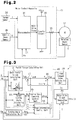
- an electric power steering apparatus (EPS) 1 has a steering wheel 2 steered by a driver, a steering shaft 3 turned together with the steering wheel 2, and a rack shaft 5 coupled to the steering shaft 3 via a rack-and-pinion mechanism 4.
- EPS electric power steering apparatus
- the steering shaft 3 Upon operation of the steering wheel 2, the steering shaft 3 is rotated. The rotation of the steering shaft 3 is converted into reciprocating linear movement of the rack shaft 5 by the rack-and-pinion mechanism 4. By this reciprocating linear movement of the rack shaft 5, an actual turning angle ⁇ ps of tires is changed.
- the EPS 1 also has an EPS actuator 10 and a motor control apparatus 11 controlling the movement of the EPS actuator 10.
- the EPS actuator 10 provides a steering system with an assist force for assisting steering operation.
- the EPS actuator 10 has a motor 12 serving as a driving source, and a speed reduction mechanism 13. As the motor 12, a brushless motor is employed.
- the driving force of the motor 12 is transmitted to the steering shaft 3 after speed reduction through the speed reduction mechanism 13.
- the assist torque is provided to the steering system such as the steering wheel 2, the steering shaft 3, etc.
- the motor control apparatus 11 is connected to a vehicle speed sensor 26 and a torque sensor 24.
- the vehicle speed sensor 26 detects a vehicle speed V and outputs the detection result to the motor control apparatus 11.
- a torsion bar 15 is provided in the middle of the steering shaft 3.
- the torque sensor 24 detects a steering torque Th to be transmitted to the steering shaft 3 based on torsion of the torsion bar 15, and then outputs the detection result to the motor control apparatus 11.
- the motor control apparatus 11 has a microcomputer 31 outputting a motor drive signal, and an inverter circuit 30 supplying the motor 12 with driving power based on the motor drive signal.
- a current sensor 35 for detecting an actual current value I is provided between the inverter circuit 30 and the motor 12. Further, the motor 12 is provided with a rotation angle sensor 7 for detecting a motor rotation angle ⁇ m. The rotation angle sensor 7 outputs the detected motor rotation angle ⁇ m to the microcomputer 31.
- the microcomputer 31 has an assist torque calculating unit 40, a current command value calculating unit 28, and a motor drive signal generating unit 29.
- the assist torque calculating unit 40 calculates an assist torque command value Tas to be generated in the motor 12 based on the steering torque Th and the vehicle speed V, and then outputs the calculation result to the current command value calculating unit 28.
- the current command value calculating unit 28 calculates a current command value Ic corresponding to the assist torque command value Tas, and then outputs the calculation result to the motor drive signal generating unit 29.
- the motor drive signal generating unit 29 generates a motor drive signal by executing current feedback control to have the actual current value I follow the current command value Ic.
- the inverter circuit 30 drives the motor 12 based on the motor drive signal (the actual current value I) from the motor drive signal generating unit 29.
- the assist torque is applied to the steering shaft 3 through driving of the motor 12.
- the assist torque calculating unit 40 has a basic assist torque calculating unit 41, a target turning angle calculating unit 44, a turning angle feedback control unit 45, a turning angle calculating unit 43, an adder 46, a subtractor 47, and a road information control unit 50.
- Each control block in this assist torque calculating unit 40 is implemented by a computer program executed by the microcomputer 31.
- the basic assist torque calculating unit 41 calculates a basic assist torque command value Tab based on the steering torque Th detected by the torque sensor 24 and the vehicle speed V detected by the vehicle speed sensor 26, and then outputs the calculation result to the subtractor 47.
- the basic assist torque calculating unit 41 increases the basic assist torque command value Tab as the steering torque Th becomes larger.
- the basic assist torque calculating unit 41 also decreases the basic assist torque command value Tab as the vehicle speed V becomes faster.
- the subtractor 47 calculates a basic assist torque command value Tab* by subtracting from the basic assist torque command value Tab an RIF (road information) command value Trif* from the road information control unit 50, and then outputs the calculated basic assist torque command value Tab* to the target turning angle calculating unit 44 and the adder 46, respectively.
- the target turning angle calculating unit 44 calculates a target turning angle ⁇ p based on the steering torque Th and the basic assist torque command value Tab*, and then outputs the calculation result to the turning angle feedback control unit 45.
- the target turning angle ⁇ p is an ideal tire turning angle (steering turning angle) depending on a total torque Tt obtained by summing the steering torque Th and the basic assist torque command value Tab*. This total torque Tt corresponds to input torque.
- the turning angle calculating unit 43 calculates an actual turning angle ⁇ ps based on the motor rotation angle ⁇ m detected through the rotation angle sensor 7, and then outputs the calculation result to the turning angle feedback control unit 45 and the road information control unit 50, respectively.
- the adder 46 calculates an assist torque command value Tas by adding an assist torque correction value ⁇ Tab from the turning angle feedback control unit 45 to the basic assist torque command value Tab*, and then outputs the calculation result to the current command value calculating unit 28.
- the turning angle feedback control unit 45 executes feedback control so as for the actual turning angle ⁇ ps to be the target turning angle ⁇ p through adjustment to the magnitude of the assist torque correction value ⁇ Tab. Consequently, the magnitude of the assist torque correction value ⁇ Tab is adjusted so as for the actual turning angle ⁇ ps to be the target turning angle ⁇ p even when the rack-and-pinion mechanism 4 vibrates due to reverse input torque transmitted from the steerable wheel to the steering system, for example. Accordingly, vibration of the steering wheel 2 associated with road surface conditions can be suppressed. Thus, a more stable steering feeling can be obtained.
- the road information control unit 50 has a switching control unit 55, an end-determination-time gain calculating unit 54, an end determination unit 56, a normal-time gain calculating unit 52, a multiplier 53, and an adder 58.
- the road information control unit 50 can freely control an RIF (road information) gain Krif between "0" and "1".
- the road information control unit 50 transmits reverse input torque according to the magnitude of the RIF gain Krif as road information to the steering wheel 2 through the output of the RIF command value Trif* to the subtractor 47.
- the RIF gain Krif is "0" for example, the reverse input torque is completely removed and the road information is not provided to the steering wheel 2.
- the RIF command value Trif* to be input to the subtractor 47 takes the same value as the assist torque correction value ⁇ Tab, as shown in Figs. 3 and 4 .
- the RIF command value Trif* to be input to the subtractor 47 cancels the assist torque correction value ⁇ Tab to be input to the adder 46.
- the control to make the actual turning angle ⁇ ps be the target turning angle ⁇ p by the turning angle feedback control unit 45 is virtually stopped when the RIF gain Krif is "1". Consequently, the reverse input torque is all provided to the steering wheel 2 as road information.
- the switching control unit 55 switches the connection status between the normal-time gain calculating unit 52 and the end-determination-time gain calculating unit 54, as shown in Fig. 4 .
- the switching control unit 55 outputs to the multiplier 53 the RIF gain Krif from the connected normal-time gain calculating unit 52 or end-determination-time gain calculating unit 54.
- the multiplier 53 multiplies the assist torque correction value ⁇ Tab and the RIF gain Krif, and then outputs the multiplied RIF command value Trif* to the subtractor 47.
- the normal-time gain calculating unit 52 calculates the RIF gain Krif according to the vehicle speed V, and then outputs the calculated RIF gain Krif to the switching control unit 55.
- the normal-time gain calculating unit 52 sets the RIF gain Krif at "1" in an area where the vehicle speed is no more than the vehicle speed V1 and sets the RIF gain Krif to be smaller as the vehicle speed V is faster in an area where the vehicle speed exceeds the vehicle speed V1.
- the adder 58 calculates an angle deviation ⁇ obtained by subtracting the target turning angle ⁇ p from the actual turning angle ⁇ ps, and then outputs the angle deviation ⁇ to the end determination unit 56. Further, the target turning angle ⁇ p and the steering torque Th are output to the end determination unit 56.
- the end determination unit 56 determines that the end touching state has been reached when the target turning angle ⁇ p becomes an angle near the end and the angle deviation ⁇ exceeds a threshold ⁇ th and then turns the end flag on.
- the end touching state means a state where an end portion of the rack shaft 5 touches against the rack housing.
- the actual turning angle ⁇ ps does not increase in response to the increase in the steering torque Th. Due to this, a difference between the target turning angle ⁇ p and the actual turning angle ⁇ ps, that is, the angle deviation ⁇ becomes large.
- the end direction corresponds to a direction opposite to a neutral position of the steering wheel 2.
- the threshold ⁇ th is set at the angle deviation ⁇ which cannot be caused except in the end touching state.
- the end determination unit 56 turns the end flag off when release conditions hold.
- the release conditions are, for example, that the actual turning angle ⁇ ps is not an angle near the end, and that the angle deviation ⁇ , a time rate of change of the angle deviation ⁇ , and the steering torque Th are no more than predetermined values.
- the end-determination-time gain calculating unit 54 monitors an on-off state of the end flag through the end determination unit 56. Then, the end-determination-time gain calculating unit 54 calculates the RIF gain Krif depending on the on-off state of the end flag and outputs the calculated RIF gain Krif to the switching control unit 55.
- the end-determination-time gain calculating unit 54 rapidly increases the RIF gain Krif from “0" to "1" when the end flag is switched from the off state to the on state at time t1 as shown in Fig. 5 . It takes a fixed time T1 until the RIF gain Krif becomes "1" from "0".
- the end-determination-time gain calculating unit 54 then gradually decreases the RIF gain Krif from “1" to "0" when the end flag is switched from the on state to the off state at time t2. It takes a fixed time T2 longer than the above fixed time T1 until the RIF gain Krif becomes "0" from “1". That is, an inclination at the time of turning the RIF gain Krif "0" from “1” is set smaller than an inclination at the time of turning the RIF gain Krif "1" from "0".
- the fixed time T2 is set for the purpose of suppressing an uncomfortable feeling in operation of the steering wheel 2 associated with a rapid start of the control to make the actual turning angle ⁇ ps be the target turning angle ⁇ p in a state of the angle deviation ⁇ being large.
- the uncomfortable feeling is caused by the application of the assist torque in the end direction when the steering wheel 2 is returned toward the neutral position from the end touching state.
- the end determination unit 56 brings the switching control unit 55 into a state connected to the normal-time gain calculating unit 52 when the end flag is off. In this state, the RIF gain Krif from the normal-time gain calculating unit 52 is output to the multiplier 53. The end determination unit 56 brings the switching control unit 55 into a state connected to the end-determination-time gain calculating unit 54 when the end flag is on.
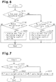
- the end determination unit 56 determines whether the actual turning angle ⁇ ps becomes an angle near the end (S101). In the step S101, the end determination unit 56 determines whether or not "- ⁇ end ⁇ ⁇ ps ⁇ + ⁇ end" holds. In this case, a positive near end angle is set to + ⁇ end, and a negative near end angle is set to - ⁇ end,
- the end determination unit 56 determines whether the angle deviation ⁇ exceeds the threshold ⁇ th (S102). When determining that the angle deviation ⁇ exceeds the threshold ⁇ th (YES in S102), the end determination unit 56 turns the end flag on and brings the switching control unit 55 into the state connected to the end-determination-time gain calculating unit 54 (S103). Now, the end determination unit 56 terminates the processing. When determining that the angle deviation ⁇ is less than the threshold ⁇ th (NO in S102), the end determination unit 56 terminates the processing without switching the end flag.
- the end determination unit 56 determines whether the foregoing release conditions hold (S104). When determining that the release conditions hold (YES in S104), the end determination unit 56 turns the end flag off and brings the switching control unit 55 into the state connected to the normal-time gain calculating unit 52 (S105). Now, the end determination unit 56 terminates the processing.
- the end-determination-time gain calculating unit 54 determines whether the end flag is on through the end determination unit 56 (S201). When determining that the end flag is on (YES in S201), the end-determination-time gain calculating unit 54 sets the target value of the RIF gain Krif at "1" (S202). As a result, the RIF gain Krif is controlled at "1" as shown in Fig. 5 .
- the end-determination-time gain calculating unit 54 sets the target value of the RIF gain Krif at "0" (S203). As a result, the RIF gain Krif is controlled at "0" as shown in Fig. 5 .
- the basic assist torque command value Tab* corresponds to the first command value
- the assist torque correction value ⁇ Tab corresponds to the second command value
- the RIF command value Trif* corresponds to the third command value
- the basic assist torque calculating unit 41 corresponds to the first control device.
- the turning angle feedback control unit 45 corresponds to the second control device.
- the end determination unit 56 corresponds to the end touch determination device.
- the current command value calculating unit 28, the motor drive signal generating unit 29, the inverter circuit 30, and the motor 12 correspond to the steering force provider.
- the target turning angle calculating unit 44 calculates the target turning angle ⁇ p based on the total torque Tt as input torque in the foregoing embodiment.
- the target turning angle ⁇ p may be calculated based on only the steering torque Th or only the basic assist torque command value Tab as the input torque.
- the RIF gain Krif is controlled at "1".
- the current command value Ic may be reduced. As a result, heat generation in the motor 12 associated with an overcurrent in the end touching state can be suppressed.
- the control to make the actual turning angle ⁇ ps be the target turning angle ⁇ p is virtually stopped at the time of being brought into the end touching state in the foregoing embodiment.
- the operation of the turning angle feedback control unit 45 may be stopped actually. In this case, the output of the RIF command value Trif* from the road information control unit 50 needs to be stopped.
Landscapes
- Engineering & Computer Science (AREA)
- Chemical & Material Sciences (AREA)
- Combustion & Propulsion (AREA)
- Transportation (AREA)
- Mechanical Engineering (AREA)
- Steering Control In Accordance With Driving Conditions (AREA)
- Power Steering Mechanism (AREA)
Applications Claiming Priority (1)
| Application Number | Priority Date | Filing Date | Title |
|---|---|---|---|
| JP2013037091A JP6036407B2 (ja) | 2013-02-27 | 2013-02-27 | 電動パワーステアリング装置 |
Publications (3)
| Publication Number | Publication Date |
|---|---|
| EP2772413A2 EP2772413A2 (en) | 2014-09-03 |
| EP2772413A3 EP2772413A3 (en) | 2015-12-30 |
| EP2772413B1 true EP2772413B1 (en) | 2017-11-22 |
Family
ID=50073056
Family Applications (1)
| Application Number | Title | Priority Date | Filing Date |
|---|---|---|---|
| EP14155006.1A Not-in-force EP2772413B1 (en) | 2013-02-27 | 2014-02-13 | Electric power steering apparatus |
Country Status (4)
| Country | Link |
|---|---|
| US (1) | US9718492B2 (zh) |
| EP (1) | EP2772413B1 (zh) |
| JP (1) | JP6036407B2 (zh) |
| CN (1) | CN104002856B (zh) |
Cited By (1)
| Publication number | Priority date | Publication date | Assignee | Title |
|---|---|---|---|---|
| US11142243B2 (en) * | 2018-01-30 | 2021-10-12 | Jtekt Corporation | Steering control device |
Families Citing this family (9)
| Publication number | Priority date | Publication date | Assignee | Title |
|---|---|---|---|---|
| JP2016088436A (ja) * | 2014-11-10 | 2016-05-23 | 株式会社デンソー | モータ制御装置 |
| KR101736136B1 (ko) * | 2015-12-07 | 2017-05-16 | 현대모비스 주식회사 | 전동식 파워 스티어링 시스템 및 그 제어방법 |
| KR102341111B1 (ko) * | 2015-12-14 | 2021-12-21 | 현대모비스 주식회사 | 전동식 조향 장치 및 그 제어 방법 |
| CN111098915A (zh) * | 2018-10-26 | 2020-05-05 | 上汽通用汽车有限公司 | 转向机构行程限位保护控制方法、计算机可读存储介质以及转向机构行程限位保护控制系统 |
| EP3946833B1 (en) * | 2019-03-29 | 2023-08-30 | Intuitive Surgical Operations, Inc. | Reducing energy buildup in servo-controlled mechanisms |
| JP7063428B1 (ja) * | 2021-03-12 | 2022-05-09 | 日本精工株式会社 | 転舵装置のエンド位置の検出装置、検出方法、およびプログラム |
| WO2022190452A1 (ja) * | 2021-03-12 | 2022-09-15 | 日本精工株式会社 | 転舵装置のエンド位置の検出装置、検出方法、およびプログラム |
| US11919580B2 (en) * | 2021-12-09 | 2024-03-05 | Ford Global Technologies, Llc | Methods and apparatus to move a steering wheel |
| CN115214773B (zh) * | 2022-03-01 | 2023-11-21 | 广州汽车集团股份有限公司 | 车辆控制方法、装置、系统、车辆及存储介质 |
Family Cites Families (21)
| Publication number | Priority date | Publication date | Assignee | Title |
|---|---|---|---|---|
| JPH0679900B2 (ja) * | 1986-03-31 | 1994-10-12 | マツダ株式会社 | 車両の4輪操舵装置 |
| US6176341B1 (en) * | 1999-02-01 | 2001-01-23 | Delphi Technologies, Inc. | Vehicle steering system having master/slave configuration and method therefor |
| JP3795827B2 (ja) | 2002-04-24 | 2006-07-12 | 株式会社ジェイテクト | 電動パワーステアリング装置 |
| JP4615899B2 (ja) * | 2004-06-07 | 2011-01-19 | 日産自動車株式会社 | 車両用旋回走行制御装置 |
| JP4277755B2 (ja) * | 2004-07-16 | 2009-06-10 | 日産自動車株式会社 | 車両用旋回走行制御装置 |
| JP4639759B2 (ja) | 2004-11-09 | 2011-02-23 | 株式会社ジェイテクト | 電動パワーステアリング装置 |
| JP4453012B2 (ja) | 2004-12-21 | 2010-04-21 | 株式会社ジェイテクト | 電動パワーステアリング装置 |
| JP4725797B2 (ja) * | 2006-06-13 | 2011-07-13 | 株式会社ジェイテクト | 車両用操舵装置 |
| JP4587050B2 (ja) * | 2006-06-13 | 2010-11-24 | 株式会社ジェイテクト | 車両用操舵装置 |
| EP1923299B1 (en) * | 2006-11-20 | 2010-09-01 | NSK Ltd. | Absolute steering angle detecting device |
| JP2008143200A (ja) * | 2006-12-06 | 2008-06-26 | Nsk Ltd | 電動パワーステアリング装置 |
| JP4905111B2 (ja) * | 2006-12-18 | 2012-03-28 | 日産自動車株式会社 | 操舵アシスト装置 |
| US7810605B2 (en) * | 2006-12-28 | 2010-10-12 | Nissan Motor Co., Ltd. | Vehicle steering device and control method for vehicle steering device |
| JP4420036B2 (ja) * | 2007-02-05 | 2010-02-24 | 日産自動車株式会社 | 車両用操舵制御装置 |
| JP2008260421A (ja) | 2007-04-12 | 2008-10-30 | Toyota Motor Corp | エンド当たり検出装置 |
| EP2374691B1 (en) * | 2007-11-06 | 2014-04-23 | Honda Motor Co., Ltd. | Electric Power Steering Device |
| JP2009143312A (ja) * | 2007-12-12 | 2009-07-02 | Toyota Motor Corp | 電動パワーステアリング装置 |
| JP5086385B2 (ja) | 2010-03-08 | 2012-11-28 | 日立オートモティブシステムズ株式会社 | 電動パワーステアリング制御装置 |
| JP5509341B2 (ja) | 2010-11-29 | 2014-06-04 | 本田技研工業株式会社 | 電動パワーステアリング装置 |
| CN103442969B (zh) | 2011-03-29 | 2016-02-17 | 株式会社捷太格特 | 电子助力转向设备 |
| JP5942726B2 (ja) | 2012-09-18 | 2016-06-29 | 株式会社ジェイテクト | 電動パワーステアリング装置 |
-
2013
- 2013-02-27 JP JP2013037091A patent/JP6036407B2/ja not_active Expired - Fee Related
-
2014
- 2014-02-10 US US14/176,719 patent/US9718492B2/en active Active
- 2014-02-13 EP EP14155006.1A patent/EP2772413B1/en not_active Not-in-force
- 2014-02-25 CN CN201410064469.1A patent/CN104002856B/zh not_active Expired - Fee Related
Non-Patent Citations (1)
| Title |
|---|
| None * |
Cited By (1)
| Publication number | Priority date | Publication date | Assignee | Title |
|---|---|---|---|---|
| US11142243B2 (en) * | 2018-01-30 | 2021-10-12 | Jtekt Corporation | Steering control device |
Also Published As
| Publication number | Publication date |
|---|---|
| CN104002856A (zh) | 2014-08-27 |
| US9718492B2 (en) | 2017-08-01 |
| JP2014162421A (ja) | 2014-09-08 |
| US20140238768A1 (en) | 2014-08-28 |
| EP2772413A3 (en) | 2015-12-30 |
| EP2772413A2 (en) | 2014-09-03 |
| CN104002856B (zh) | 2017-12-12 |
| JP6036407B2 (ja) | 2016-11-30 |
Similar Documents
| Publication | Publication Date | Title |
|---|---|---|
| EP2772413B1 (en) | Electric power steering apparatus | |
| JP6729838B2 (ja) | 車両のステアリング制御方法および車両のステアリング制御装置 | |
| EP2933169B1 (en) | Electric power steering apparatus | |
| EP1602555B1 (en) | Electric power steering apparatus | |
| JP5943018B2 (ja) | 操舵制御装置 | |
| JP2006248252A (ja) | 電動パワーステアリング装置の制御装置 | |
| JP5867612B2 (ja) | 車両用操舵制御装置及び車両用操舵制御方法 | |
| KR102344546B1 (ko) | 차량용 핸들 제어 장치 | |
| JP2008284889A (ja) | 電動パワーステアリング装置の制御装置 | |
| JP4579056B2 (ja) | 車両用操舵装置 | |
| JP7293855B2 (ja) | 操舵制御装置 | |
| JP2008143200A (ja) | 電動パワーステアリング装置 | |
| JP5131324B2 (ja) | 車両用操舵装置 | |
| JP6652742B2 (ja) | 電動パワーステアリング装置 | |
| CN113815714A (zh) | 转向系统 | |
| JP7307000B2 (ja) | 操舵制御装置 | |
| JP2005082119A (ja) | 電動パワーステアリング装置 | |
| JP5233083B2 (ja) | 電動パワーステアリング装置 | |
| JP5994649B2 (ja) | 操舵制御装置 | |
| JP4238582B2 (ja) | 車両用操舵制御装置 | |
| JP7376290B2 (ja) | 操舵制御装置 | |
| JP3884238B2 (ja) | 電動パワーステアリング装置 | |
| EP2130743B1 (en) | Electric power steering apparatus | |
| KR101172098B1 (ko) | 능동조향장치의 반력저감을 위한 전동식 파워스티어링시스템 | |
| JP5181540B2 (ja) | 電動パワーステアリング装置 |
Legal Events
| Date | Code | Title | Description |
|---|---|---|---|
| PUAI | Public reference made under article 153(3) epc to a published international application that has entered the european phase |
Free format text: ORIGINAL CODE: 0009012 |
|
| 17P | Request for examination filed |
Effective date: 20140213 |
|
| AK | Designated contracting states |
Kind code of ref document: A2 Designated state(s): AL AT BE BG CH CY CZ DE DK EE ES FI FR GB GR HR HU IE IS IT LI LT LU LV MC MK MT NL NO PL PT RO RS SE SI SK SM TR |
|
| AX | Request for extension of the european patent |
Extension state: BA ME |
|
| PUAL | Search report despatched |
Free format text: ORIGINAL CODE: 0009013 |
|
| AK | Designated contracting states |
Kind code of ref document: A3 Designated state(s): AL AT BE BG CH CY CZ DE DK EE ES FI FR GB GR HR HU IE IS IT LI LT LU LV MC MK MT NL NO PL PT RO RS SE SI SK SM TR |
|
| AX | Request for extension of the european patent |
Extension state: BA ME |
|
| RIC1 | Information provided on ipc code assigned before grant |
Ipc: B62D 6/04 20060101AFI20151120BHEP Ipc: B62D 5/04 20060101ALI20151120BHEP |
|
| R17P | Request for examination filed (corrected) |
Effective date: 20160622 |
|
| RBV | Designated contracting states (corrected) |
Designated state(s): AL AT BE BG CH CY CZ DE DK EE ES FI FR GB GR HR HU IE IS IT LI LT LU LV MC MK MT NL NO PL PT RO RS SE SI SK SM TR |
|
| GRAP | Despatch of communication of intention to grant a patent |
Free format text: ORIGINAL CODE: EPIDOSNIGR1 |
|
| INTG | Intention to grant announced |
Effective date: 20170602 |
|
| GRAS | Grant fee paid |
Free format text: ORIGINAL CODE: EPIDOSNIGR3 |
|
| GRAA | (expected) grant |
Free format text: ORIGINAL CODE: 0009210 |
|
| AK | Designated contracting states |
Kind code of ref document: B1 Designated state(s): AL AT BE BG CH CY CZ DE DK EE ES FI FR GB GR HR HU IE IS IT LI LT LU LV MC MK MT NL NO PL PT RO RS SE SI SK SM TR |
|
| REG | Reference to a national code |
Ref country code: GB Ref legal event code: FG4D |
|
| RIN1 | Information on inventor provided before grant (corrected) |
Inventor name: EKI, HIROZUMI Inventor name: NAMIKAWA, ISAO Inventor name: KITA, MASAYUKI Inventor name: TAMAIZUMI, TERUTAKA |
|
| REG | Reference to a national code |
Ref country code: CH Ref legal event code: EP |
|
| REG | Reference to a national code |
Ref country code: IE Ref legal event code: FG4D |
|
| REG | Reference to a national code |
Ref country code: AT Ref legal event code: REF Ref document number: 948111 Country of ref document: AT Kind code of ref document: T Effective date: 20171215 |
|
| REG | Reference to a national code |
Ref country code: DE Ref legal event code: R096 Ref document number: 602014017443 Country of ref document: DE |
|
| REG | Reference to a national code |
Ref country code: FR Ref legal event code: PLFP Year of fee payment: 5 |
|
| REG | Reference to a national code |
Ref country code: NL Ref legal event code: MP Effective date: 20171122 |
|
| REG | Reference to a national code |
Ref country code: LT Ref legal event code: MG4D |
|
| REG | Reference to a national code |
Ref country code: AT Ref legal event code: MK05 Ref document number: 948111 Country of ref document: AT Kind code of ref document: T Effective date: 20171122 |
|
| PG25 | Lapsed in a contracting state [announced via postgrant information from national office to epo] |
Ref country code: NO Free format text: LAPSE BECAUSE OF FAILURE TO SUBMIT A TRANSLATION OF THE DESCRIPTION OR TO PAY THE FEE WITHIN THE PRESCRIBED TIME-LIMIT Effective date: 20180222 Ref country code: FI Free format text: LAPSE BECAUSE OF FAILURE TO SUBMIT A TRANSLATION OF THE DESCRIPTION OR TO PAY THE FEE WITHIN THE PRESCRIBED TIME-LIMIT Effective date: 20171122 Ref country code: LT Free format text: LAPSE BECAUSE OF FAILURE TO SUBMIT A TRANSLATION OF THE DESCRIPTION OR TO PAY THE FEE WITHIN THE PRESCRIBED TIME-LIMIT Effective date: 20171122 Ref country code: NL Free format text: LAPSE BECAUSE OF FAILURE TO SUBMIT A TRANSLATION OF THE DESCRIPTION OR TO PAY THE FEE WITHIN THE PRESCRIBED TIME-LIMIT Effective date: 20171122 Ref country code: SE Free format text: LAPSE BECAUSE OF FAILURE TO SUBMIT A TRANSLATION OF THE DESCRIPTION OR TO PAY THE FEE WITHIN THE PRESCRIBED TIME-LIMIT Effective date: 20171122 Ref country code: ES Free format text: LAPSE BECAUSE OF FAILURE TO SUBMIT A TRANSLATION OF THE DESCRIPTION OR TO PAY THE FEE WITHIN THE PRESCRIBED TIME-LIMIT Effective date: 20171122 |
|
| PG25 | Lapsed in a contracting state [announced via postgrant information from national office to epo] |
Ref country code: AT Free format text: LAPSE BECAUSE OF FAILURE TO SUBMIT A TRANSLATION OF THE DESCRIPTION OR TO PAY THE FEE WITHIN THE PRESCRIBED TIME-LIMIT Effective date: 20171122 Ref country code: HR Free format text: LAPSE BECAUSE OF FAILURE TO SUBMIT A TRANSLATION OF THE DESCRIPTION OR TO PAY THE FEE WITHIN THE PRESCRIBED TIME-LIMIT Effective date: 20171122 Ref country code: RS Free format text: LAPSE BECAUSE OF FAILURE TO SUBMIT A TRANSLATION OF THE DESCRIPTION OR TO PAY THE FEE WITHIN THE PRESCRIBED TIME-LIMIT Effective date: 20171122 Ref country code: LV Free format text: LAPSE BECAUSE OF FAILURE TO SUBMIT A TRANSLATION OF THE DESCRIPTION OR TO PAY THE FEE WITHIN THE PRESCRIBED TIME-LIMIT Effective date: 20171122 Ref country code: GR Free format text: LAPSE BECAUSE OF FAILURE TO SUBMIT A TRANSLATION OF THE DESCRIPTION OR TO PAY THE FEE WITHIN THE PRESCRIBED TIME-LIMIT Effective date: 20180223 Ref country code: BG Free format text: LAPSE BECAUSE OF FAILURE TO SUBMIT A TRANSLATION OF THE DESCRIPTION OR TO PAY THE FEE WITHIN THE PRESCRIBED TIME-LIMIT Effective date: 20180222 |
|
| PG25 | Lapsed in a contracting state [announced via postgrant information from national office to epo] |
Ref country code: SK Free format text: LAPSE BECAUSE OF FAILURE TO SUBMIT A TRANSLATION OF THE DESCRIPTION OR TO PAY THE FEE WITHIN THE PRESCRIBED TIME-LIMIT Effective date: 20171122 Ref country code: CY Free format text: LAPSE BECAUSE OF FAILURE TO SUBMIT A TRANSLATION OF THE DESCRIPTION OR TO PAY THE FEE WITHIN THE PRESCRIBED TIME-LIMIT Effective date: 20171122 Ref country code: EE Free format text: LAPSE BECAUSE OF FAILURE TO SUBMIT A TRANSLATION OF THE DESCRIPTION OR TO PAY THE FEE WITHIN THE PRESCRIBED TIME-LIMIT Effective date: 20171122 Ref country code: CZ Free format text: LAPSE BECAUSE OF FAILURE TO SUBMIT A TRANSLATION OF THE DESCRIPTION OR TO PAY THE FEE WITHIN THE PRESCRIBED TIME-LIMIT Effective date: 20171122 Ref country code: DK Free format text: LAPSE BECAUSE OF FAILURE TO SUBMIT A TRANSLATION OF THE DESCRIPTION OR TO PAY THE FEE WITHIN THE PRESCRIBED TIME-LIMIT Effective date: 20171122 |
|
| REG | Reference to a national code |
Ref country code: DE Ref legal event code: R097 Ref document number: 602014017443 Country of ref document: DE |
|
| PG25 | Lapsed in a contracting state [announced via postgrant information from national office to epo] |
Ref country code: SM Free format text: LAPSE BECAUSE OF FAILURE TO SUBMIT A TRANSLATION OF THE DESCRIPTION OR TO PAY THE FEE WITHIN THE PRESCRIBED TIME-LIMIT Effective date: 20171122 Ref country code: PL Free format text: LAPSE BECAUSE OF FAILURE TO SUBMIT A TRANSLATION OF THE DESCRIPTION OR TO PAY THE FEE WITHIN THE PRESCRIBED TIME-LIMIT Effective date: 20171122 Ref country code: RO Free format text: LAPSE BECAUSE OF FAILURE TO SUBMIT A TRANSLATION OF THE DESCRIPTION OR TO PAY THE FEE WITHIN THE PRESCRIBED TIME-LIMIT Effective date: 20171122 Ref country code: IT Free format text: LAPSE BECAUSE OF FAILURE TO SUBMIT A TRANSLATION OF THE DESCRIPTION OR TO PAY THE FEE WITHIN THE PRESCRIBED TIME-LIMIT Effective date: 20171122 |
|
| REG | Reference to a national code |
Ref country code: CH Ref legal event code: PL |
|
| PG25 | Lapsed in a contracting state [announced via postgrant information from national office to epo] |
Ref country code: MC Free format text: LAPSE BECAUSE OF FAILURE TO SUBMIT A TRANSLATION OF THE DESCRIPTION OR TO PAY THE FEE WITHIN THE PRESCRIBED TIME-LIMIT Effective date: 20171122 |
|
| PLBE | No opposition filed within time limit |
Free format text: ORIGINAL CODE: 0009261 |
|
| STAA | Information on the status of an ep patent application or granted ep patent |
Free format text: STATUS: NO OPPOSITION FILED WITHIN TIME LIMIT |
|
| GBPC | Gb: european patent ceased through non-payment of renewal fee |
Effective date: 20180222 |
|
| 26N | No opposition filed |
Effective date: 20180823 |
|
| REG | Reference to a national code |
Ref country code: BE Ref legal event code: MM Effective date: 20180228 |
|
| PG25 | Lapsed in a contracting state [announced via postgrant information from national office to epo] |
Ref country code: SI Free format text: LAPSE BECAUSE OF FAILURE TO SUBMIT A TRANSLATION OF THE DESCRIPTION OR TO PAY THE FEE WITHIN THE PRESCRIBED TIME-LIMIT Effective date: 20171122 Ref country code: CH Free format text: LAPSE BECAUSE OF NON-PAYMENT OF DUE FEES Effective date: 20180228 Ref country code: LU Free format text: LAPSE BECAUSE OF NON-PAYMENT OF DUE FEES Effective date: 20180213 Ref country code: LI Free format text: LAPSE BECAUSE OF NON-PAYMENT OF DUE FEES Effective date: 20180228 |
|
| REG | Reference to a national code |
Ref country code: IE Ref legal event code: MM4A |
|
| PG25 | Lapsed in a contracting state [announced via postgrant information from national office to epo] |
Ref country code: IE Free format text: LAPSE BECAUSE OF NON-PAYMENT OF DUE FEES Effective date: 20180213 |
|
| PG25 | Lapsed in a contracting state [announced via postgrant information from national office to epo] |
Ref country code: GB Free format text: LAPSE BECAUSE OF NON-PAYMENT OF DUE FEES Effective date: 20180222 Ref country code: BE Free format text: LAPSE BECAUSE OF NON-PAYMENT OF DUE FEES Effective date: 20180228 |
|
| PG25 | Lapsed in a contracting state [announced via postgrant information from national office to epo] |
Ref country code: MT Free format text: LAPSE BECAUSE OF NON-PAYMENT OF DUE FEES Effective date: 20180213 |
|
| PG25 | Lapsed in a contracting state [announced via postgrant information from national office to epo] |
Ref country code: TR Free format text: LAPSE BECAUSE OF FAILURE TO SUBMIT A TRANSLATION OF THE DESCRIPTION OR TO PAY THE FEE WITHIN THE PRESCRIBED TIME-LIMIT Effective date: 20171122 |
|
| PG25 | Lapsed in a contracting state [announced via postgrant information from national office to epo] |
Ref country code: HU Free format text: LAPSE BECAUSE OF FAILURE TO SUBMIT A TRANSLATION OF THE DESCRIPTION OR TO PAY THE FEE WITHIN THE PRESCRIBED TIME-LIMIT; INVALID AB INITIO Effective date: 20140213 Ref country code: PT Free format text: LAPSE BECAUSE OF FAILURE TO SUBMIT A TRANSLATION OF THE DESCRIPTION OR TO PAY THE FEE WITHIN THE PRESCRIBED TIME-LIMIT Effective date: 20171122 |
|
| PG25 | Lapsed in a contracting state [announced via postgrant information from national office to epo] |
Ref country code: MK Free format text: LAPSE BECAUSE OF NON-PAYMENT OF DUE FEES Effective date: 20171122 |
|
| PG25 | Lapsed in a contracting state [announced via postgrant information from national office to epo] |
Ref country code: AL Free format text: LAPSE BECAUSE OF FAILURE TO SUBMIT A TRANSLATION OF THE DESCRIPTION OR TO PAY THE FEE WITHIN THE PRESCRIBED TIME-LIMIT Effective date: 20171122 Ref country code: IS Free format text: LAPSE BECAUSE OF FAILURE TO SUBMIT A TRANSLATION OF THE DESCRIPTION OR TO PAY THE FEE WITHIN THE PRESCRIBED TIME-LIMIT Effective date: 20180322 |
|
| PGFP | Annual fee paid to national office [announced via postgrant information from national office to epo] |
Ref country code: DE Payment date: 20211230 Year of fee payment: 9 |
|
| PGFP | Annual fee paid to national office [announced via postgrant information from national office to epo] |
Ref country code: FR Payment date: 20220118 Year of fee payment: 9 |
|
| REG | Reference to a national code |
Ref country code: DE Ref legal event code: R119 Ref document number: 602014017443 Country of ref document: DE |
|
| PG25 | Lapsed in a contracting state [announced via postgrant information from national office to epo] |
Ref country code: FR Free format text: LAPSE BECAUSE OF NON-PAYMENT OF DUE FEES Effective date: 20230228 Ref country code: DE Free format text: LAPSE BECAUSE OF NON-PAYMENT OF DUE FEES Effective date: 20230901 |