EP2770136B1 - Befestigungswinkel für deckenrandabschalungen - Google Patents
Befestigungswinkel für deckenrandabschalungen Download PDFInfo
- Publication number
- EP2770136B1 EP2770136B1 EP14405010.1A EP14405010A EP2770136B1 EP 2770136 B1 EP2770136 B1 EP 2770136B1 EP 14405010 A EP14405010 A EP 14405010A EP 2770136 B1 EP2770136 B1 EP 2770136B1
- Authority
- EP
- European Patent Office
- Prior art keywords
- limb
- retaining
- ceiling
- formwork
- fastening
- Prior art date
- Legal status (The legal status is an assumption and is not a legal conclusion. Google has not performed a legal analysis and makes no representation as to the accuracy of the status listed.)
- Active
Links
Images
Classifications
-
- E—FIXED CONSTRUCTIONS
- E04—BUILDING
- E04G—SCAFFOLDING; FORMS; SHUTTERING; BUILDING IMPLEMENTS OR AIDS, OR THEIR USE; HANDLING BUILDING MATERIALS ON THE SITE; REPAIRING, BREAKING-UP OR OTHER WORK ON EXISTING BUILDINGS
- E04G11/00—Forms, shutterings, or falsework for making walls, floors, ceilings, or roofs
- E04G11/36—Forms, shutterings, or falsework for making walls, floors, ceilings, or roofs for floors, ceilings, or roofs of plane or curved surfaces end formpanels for floor shutterings
- E04G11/365—Stop-end shutterings
-
- E—FIXED CONSTRUCTIONS
- E04—BUILDING
- E04B—GENERAL BUILDING CONSTRUCTIONS; WALLS, e.g. PARTITIONS; ROOFS; FLOORS; CEILINGS; INSULATION OR OTHER PROTECTION OF BUILDINGS
- E04B5/00—Floors; Floor construction with regard to insulation; Connections specially adapted therefor
- E04B5/16—Load-carrying floor structures wholly or partly cast or similarly formed in situ
- E04B5/32—Floor structures wholly cast in situ with or without form units or reinforcements
- E04B2005/322—Floor structures wholly cast in situ with or without form units or reinforcements with permanent forms for the floor edges
Definitions
- Fastening brackets also called shuttering brackets, are used to fasten shuttering boards or, in the case of lost formwork, to fasten shuttering that remains on the building after the ceiling has been concreted.
- the mounting brackets are usually attached to the ceiling formwork with nails, then the formwork is also attached to the mounting brackets with nails.
- the mounting brackets are set in the concrete for the ceiling and are then no longer visible.
- the known shuttering or mounting brackets are made of steel or plastic. Since purchases in construction are very cost-conscious and steel angles are more expensive than those made of plastic, various types of plastic angles are known. These include a base leg that extends into spaced position comes to lie to the ceiling shuttering and at right angles to it a bracket on which so-called nail loops, ie small spacers, are formed, which ensure a distance between the shuttering board and the retaining leg. The nails with which the shuttering board is attached to the spacer are passed through the nail loops. Since plastic angles must also have a certain minimum rigidity in order to be able to absorb the forces of the liquid concrete mass without the shuttering slab leaning outwards, precautions must be taken to ensure high rigidity.
- Another task is to make the mounting bracket easier by means of suitable structural measures, i.e. to be able to produce with less plastic in order to reduce its production costs without reducing the rigidity.
- nail loops are formed on the protruding part of the retaining leg, through which nails can be hammered into the slab edge formwork and hold it in place at the point most stressed by the liquid concrete mass.
- one or more nail loops 16 can also be formed on the spur 15, through the holes 19 of which nails can be driven into the ceiling edge formwork (ceiling edge formwork not shown) in order to carry the latter and especially the latter in the to hold a predetermined position.
Description
- Gegenstand der Erfindung ist ein Befestigungswinkel für Deckenrandabschalungen gemäss Oberbegriff des Patentanspruches 1.
- Befestigungswinkel, auch Abschalwinkel genannt, dienen zum Befestigen von Abschalbrettern oder bei verlorenen Schalungen zum Befestigen von Abschalungen, die nach dem Betonieren der Decke am Bau verbleiben. Die Befestigungswinkel werden üblicherweise auf der Deckenschalung mit Nägeln befestigt, danach wird die Abschalung ebenfalls mit Nägeln an den Befestigungswinkeln angebracht. Die Befestigungswinkel werden in der Betonmasse für die Decke einbetoniert und sind danach nicht mehr sichtbar.
- Die bekannten Abschal- oder Befestigungswinkel sind aus Stahl oder Kunststoff hergestellt. Da auf dem Bau sehr kostenbewusst eingekauft wird und Stahlwinkel teurer sind als solche, die aus Kunststoff hergestellt werden, sind demzufolge verschiedene Ausführungen von Kunststoffwinkeln bekannt. Diese umfassen einen Basisschenkel, der in beabstandeter Lage zur Deckenabschalung zu liegen kommt und rechtwinklig dazu einen Haltewinkel, an welchem sogenannte Nagelschlaufen, d.h. kleine Distanzhalter, ausgebildet sind, welche zwischen dem Schalbrett und dem Halteschenkel einen Abstand gewährleisten. Durch die Nagelschlaufen werden die Nägel hindurchgeführt, mit denen das Schalbrett am Abstandhalter befestigt wird. Da auch Kunststoffwinkel eine gewisse minimale Steifigkeit aufweisen müssen, um die Kräfte der flüssigen Betonmasse aufnehmen zu können, ohne dass sich die Abschalplatte nach aussen neigt, müssen Vorkehrungen getroffen werden, welche eine hohe Steifigkeit gewährleisten. Einerseits ist es möglich, Kunststoffmaterialien zu verwenden, die diese Voraussetzungen erfüllen. Diese sind aber sehr teuer und daher von den Abnehmern nicht akzeptiert. Weiter ist es möglich, auf andere Weise die Festigkeit des Kunststoffwinkels zu erhöhen, auch wenn dieser aus sehr kostengünstigem Material besteht. Alle diese Massnahmen, mit Ausnahme von teuren Kunststoffprodukten, können die Anforderungen an die Festigkeit (Durchbiegung) bisher nicht erfüllen.
- Das Dokument Wo
2012/113088 offenbart einen Befestigungsschenkel gemäß dem Oberbegriff des Anspruchs 1. Es ist daher eine Aufgabe der vorliegenden Erfindung, einen Befestigungswinkel zu schaffen, dessen Steifigkeit trotz Verwendung von kostengünstigem Kunststoff alle Anforderungen an die Festigkeit erfüllt. - Eine weitere Aufgabe der vorliegenden Erfindung besteht darin, den Befestigungswinkel derart auszugestalten, dass insbesondere bei vorfabrizierten Decken verhindert wird, dass der Basisschenkel, der auf die Deckenschalung bzw. auf die vorfabrizierte Decke befestigt wird, durch das Gewicht der am Halteschenkel befestigten Deckenrandabschalung nicht übermässig belastet wird bzw. dass der Winkel, insbesondere wenn er aus Kunststoff hergestellt ist, nicht übermässig auf Biegung belastet wird.
- Eine weitere Aufgabe besteht darin, den Befestigungswinkel durch geeignete konstruktive Massnahmen leichter auszubilden, d.h. mit weniger Kunststoff herstellen zu können, um dessen Herstellungskosten zu senken, ohne die Steifigkeit zu vermindern.
- Gelöst werden diese Aufgaben durch einen Befestigungswinkel mit den Merkmalen des Patentanspruchs 1. Vorteilhafte Ausgestaltungen des Befestigungswinkels sind in den abhängigen Ansprüchen umschrieben.
- Durch die Verlängerung des Halteschenkels über die Unterseite des Basisschenkels hinaus kann der über die Mauerkrone hinausstehende bzw. hinausragende Teil des Befestigungswinkels auf der Mauerkrone abgestützt und dadurch können die Kräfte einerseits durch das Gewicht der Deckenrandabschalung vollständig aufgenommen werden. In einer besonders vorteilhaften Ausgestaltung der Erfindung ist der nach unten überstehende Teil des Halteschenkels mit Sollbruchlinien beispielsweise im Abstand von 10mm versehen, so dass je nach Abstand der Sohle des Basisschenkels von der Krone der Wand an die Gegebenheiten angepasst werden kann.
- In einer weiteren vorteilhaften Ausführung sind am vorstehenden Teil des Halteschenkels Nagelschlaufen ausgebildet, durch welche Nägel in die Deckenrandabschalung einschlagbar sind und diese an der durch die flüssige Betonmasse am meisten belasteten Stelle festhalten.
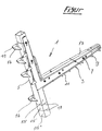
- Anhand eines illustrierten Ausführungsbeispiels wird die Erfindung näher erläutert. Es zeigt die einzige
- Figur
- eine perspektivische Darstellung eines Versteifungswinkels.
- Der in der Figur mit Bezugszeichen 1 bezeichnete Befestigungs- oder Abschalwinkel, kurz Winkel 1 genannt, umfasst einen Basisschenkel 3 und einen Halteschenkel 5. Die beiden Schenkel 3, 5 sind derart miteinander verbunden, dass die Auflageflächen 7 am Basisschenkel in einem rechten Winkel zum Halteschenkel bzw. zu den Stirnflächen von am Halteschenkel 5 angebrachten Nagelschlaufen 9 stehen.
- Der Basisschenkel 3 umfasst eine untere Deckplatte 11 und eine obere Deckplatte 13. An der unteren Deckplatte 11 sind Füsse 9 angeformt, welche die Auflagefläche 7 auf der Deckenschalung bilden. Zwischen den beiden im Beispiel leicht konisch zueinander liegenden Deckplatten 11 und 13 ist üblicherweise ein Fachwerk ausgebildet, welches durch dachartig liegende Streben gebildet wird (nicht sichtbar). Bei einer besonders vorteilhaften Ausgestaltung eines bekannten Befestigungswinkels (
WO 2012/113088 ), wie er als Beispiel in der einzigen Figur dargestellt ist, kann auch auf eine oder beide Seitenflächen des Basisschenkels 3 und des Halteschenkels 5 ein L-förmiger Versteifungswinkel 33 aufgesetzt sein. Der Versteifungswinkel 33 stellt eine Option dar und ist nur an besonders hoch beanspruchten Befestigungswinkeln 1 notwendig. - Gegenüber den bekannten Befestigungswinkeln ist erfindungsgemäss der Halteschenkel 5 über die Basis bzw. die untere Deckplatte 11 des Basisschenkels 3 hinaus durch einen Sporn 15 verlängert. Der Sporn 15 hat beispielsweise eine Minimallänge von 5cm; er kann aber auch wesentlich länger ausgebildet sein, wobei der über den Grundsporn 15 hinausragende Bereich in Abschnitte 15' und 15" unterteilt ist. Die Abschnitte 15' und 15" sind mit Sollbruchlinien 17 leicht vom jeweils darüber liegenden Teil abtrennbar.
- Wie am oberhalb des Basisschenkels 3 liegenden Bereich des Halteschenkels 5 können auch am Sporn 15 eine oder mehrere Nagelschlaufen 16 ausgebildet sein, durch deren Bohrungen 19 Nägel in die Deckenrandabschalung (Deckenrandabschalung nicht dargestellt) eintreibbar sind, um letztere zu tragen und vor allem letztere in der vorbestimmten Lage zu halten.
- Die Montage der Befestigungs- und Abschalwinkel 1 erfolgt in gewohnter Weise vor dem Betonieren der Decke des Gebäudes. Ist der Sporn 15 zu lang, d.h. der Basisschenkel 13 liegt nicht parallel zur Deckenschalung, weil der Sporn 15 an der Krone der Wand aufliegt, so kann ein Teilstück entlang der Sollbruchlinie 17 abgetrennt werden oder falls der Sporn 15 zu kurz ist, kann eine Unterlage beispielsweise aus Metall, Stein, Kunststoff oder Holz zwischen das untere Ende des Sporns 15 und die Krone geschoben oder aufgesteckt werden, so dass der Befestigung- und Abschalwinkel in der Vertikalen einwandfrei abgestützt ist.
-
- 1
- Befestigungswinkel
- 3
- Basisschenkel
- 5
- Halteschenkel
- 7
- Auflagefläche(n)
- 9
- Füsse
- 11
- untere Deckplatte
- 13
- obere Deckplatte
- 15
- Sporn
- 16
- Nagelschlaufe
- 17
- Sollbruchlinie
- 19
- Bohrung
Claims (4)
- Befestigungswinkel (1) für Deckenrandabschalungen, umfassend einen Basisschenkel (3) zu dessen Befestigung auf einer Deckenschalung, einen dazu rechtwinkelig angeordneten Halteschenkel (5) zum Befestigen einer Deckenrand-Abschalplatte sowie am Halteschenkel (5) angeordnete Nagelschlaufen (16) zum beabstandeten Halten einer Abschalplatte der Deckenrandabschalung, wobei der Basisschenkel (3) eine obere und eine untere Deckplatte (13,11) aufweist, zwischen denen ein Fachwerk oder eine Strebe ausgebildet ist, wobei an der unteren Deckplatte (11) Füsse (9) angeformt sind, welche den Basisschenkel (3) beabstandet zur Deckenschalung halten,
dadurch gekennzeichnet, dass
der Halteschenkel (5) über die untere Deckplatte (11) des Basisschenkels (3) hinaus durch einen Sporn (15) mit gleichem Querschnitt wie der Halteschenkel (5) verlängert ist. - Befestigungswinkel nach Anspruch 1, dadurch gekennzeichnet, dass am Sporn (15) entlang von Sollbruchlinien (17) abtrennbare Abschnitte (15', 15") ausgebildet sind.
- Befestigungswinkel nach einem der Ansprüche 1 oder 2,
dadurch gekennzeichnet, dass am Sporn (15) eine oder mehrere Nagelschlaufen (16) ausgebildet sind. - Befestigungswinkel nach einem der Ansprüche 1 bis 3,
dadurch gekennzeichnet, dass an einer Seitenfläche des Basisschenkels (3) und des Halteschenkels (5) ein L-förmiger Versteifungswinkel (33) aufgesetzt ist.
Applications Claiming Priority (1)
| Application Number | Priority Date | Filing Date | Title |
|---|---|---|---|
| CH00484/13A CH707643A2 (de) | 2013-02-20 | 2013-02-20 | Befestigungswinkel für Deckenrandabschalungen. |
Publications (3)
| Publication Number | Publication Date |
|---|---|
| EP2770136A2 EP2770136A2 (de) | 2014-08-27 |
| EP2770136A3 EP2770136A3 (de) | 2015-01-14 |
| EP2770136B1 true EP2770136B1 (de) | 2020-12-09 |
Family
ID=50193426
Family Applications (1)
| Application Number | Title | Priority Date | Filing Date |
|---|---|---|---|
| EP14405010.1A Active EP2770136B1 (de) | 2013-02-20 | 2014-02-11 | Befestigungswinkel für deckenrandabschalungen |
Country Status (2)
| Country | Link |
|---|---|
| EP (1) | EP2770136B1 (de) |
| CH (1) | CH707643A2 (de) |
Families Citing this family (1)
| Publication number | Priority date | Publication date | Assignee | Title |
|---|---|---|---|---|
| CH714812B1 (de) * | 2018-03-20 | 2022-02-28 | Albanese Pino | Erweiterungselement für einen Abschalwinkel. |
Family Cites Families (4)
| Publication number | Priority date | Publication date | Assignee | Title |
|---|---|---|---|---|
| DE8809429U1 (de) * | 1988-07-23 | 1988-09-22 | Loetzke, Wolfgang, 4500 Osnabrueck, De | |
| CH685830A5 (de) * | 1993-04-22 | 1995-10-13 | Bauku Bau Kunststoff Ag | Deckenabschalungskonstruktion. |
| ATE389759T1 (de) * | 2005-06-22 | 2008-04-15 | Ulrich Maag | Dachrandeement |
| CH704519A1 (de) * | 2011-02-23 | 2012-08-31 | Pino Albanese | Befestigungswinkel für Deckenrandabschalungen. |
-
2013
- 2013-02-20 CH CH00484/13A patent/CH707643A2/de unknown
-
2014
- 2014-02-11 EP EP14405010.1A patent/EP2770136B1/de active Active
Non-Patent Citations (1)
| Title |
|---|
| None * |
Also Published As
| Publication number | Publication date |
|---|---|
| EP2770136A3 (de) | 2015-01-14 |
| EP2770136A2 (de) | 2014-08-27 |
| CH707643A2 (de) | 2014-08-29 |
Similar Documents
| Publication | Publication Date | Title |
|---|---|---|
| DE202005014402U1 (de) | Ringbalkenschalung | |
| DE1559025A1 (de) | Aussteifungs- und Belegelement fuer Holz- und Metallgerueste | |
| EP2977526B1 (de) | Befestigungswinkel für deckenrandabschalungen | |
| EP2770136B1 (de) | Befestigungswinkel für deckenrandabschalungen | |
| WO2018007420A1 (de) | Ausgleichselement | |
| DE202007011315U1 (de) | Schalungselement | |
| EP2290167A1 (de) | Durchstanzbewehrung | |
| DE102015208238B4 (de) | Randschalungselement mit einer Schalungsplatte zur Herstellung einer Betonplatte | |
| DE102010025042A1 (de) | Stahlträger für Fertigteildecken | |
| DE102017206316B3 (de) | Schalungselement | |
| DE202015106999U1 (de) | Verbesserte Schalungsstruktur zur Ausführung von Horizontalgüssen zur Bereitstellung von Decken | |
| DE102008010696A1 (de) | Holzfußboden für den Außenbereich | |
| DE954373C (de) | Abstandhalter fuer Stahlbeton-Bewehrungseinlagen | |
| EP2143851B1 (de) | Bewehrungselement für die Aufnahme von Kräften in Randbereichen von betonierten Platten im Bereich von Stützelementen | |
| EP0071187A2 (de) | Haltevorrichtung für Schalbretter bei Deckenbetonierungen od. dgl. | |
| AT10698U1 (de) | Verbindungselement und hohlwandelement mit solchen verbindungselementen | |
| DE102016118754A1 (de) | Keramische Verbundplatte | |
| DE102004026914A1 (de) | Schaltafel zur Ausbildung einer Schalung | |
| DE102015017166B4 (de) | Randschalungselement mit einer als verlorene Schalung dienenden Schalungsplatte zur Herstellung einer Betonplatte | |
| DE20316442U1 (de) | Schalungsvorrichtung für Bauwerke in Stahlbetonausführung | |
| AT233809B (de) | Schalung für Betonwände von Hochbauten | |
| DE102019123256A1 (de) | Bewehrung | |
| DE1212279B (de) | Gebaeude mit Platten, die zwischen Stuetzen verlaufende Waende bilden | |
| CH322908A (de) | Schalungsträger, insbesondere zum Betonieren von Betondecken. | |
| DE202017102194U1 (de) | Schalungselement |
Legal Events
| Date | Code | Title | Description |
|---|---|---|---|
| PUAI | Public reference made under article 153(3) epc to a published international application that has entered the european phase |
Free format text: ORIGINAL CODE: 0009012 |
|
| 17P | Request for examination filed |
Effective date: 20140211 |
|
| AK | Designated contracting states |
Kind code of ref document: A2 Designated state(s): AL AT BE BG CH CY CZ DE DK EE ES FI FR GB GR HR HU IE IS IT LI LT LU LV MC MK MT NL NO PL PT RO RS SE SI SK SM TR |
|
| AX | Request for extension of the european patent |
Extension state: BA ME |
|
| PUAL | Search report despatched |
Free format text: ORIGINAL CODE: 0009013 |
|
| AK | Designated contracting states |
Kind code of ref document: A3 Designated state(s): AL AT BE BG CH CY CZ DE DK EE ES FI FR GB GR HR HU IE IS IT LI LT LU LV MC MK MT NL NO PL PT RO RS SE SI SK SM TR |
|
| AX | Request for extension of the european patent |
Extension state: BA ME |
|
| RIC1 | Information provided on ipc code assigned before grant |
Ipc: E04B 5/32 20060101ALN20141209BHEP Ipc: E04G 11/36 20060101AFI20141209BHEP |
|
| R17P | Request for examination filed (corrected) |
Effective date: 20150203 |
|
| RBV | Designated contracting states (corrected) |
Designated state(s): AL AT BE BG CH CY CZ DE DK EE ES FI FR GB GR HR HU IE IS IT LI LT LU LV MC MK MT NL NO PL PT RO RS SE SI SK SM TR |
|
| 17Q | First examination report despatched |
Effective date: 20160623 |
|
| GRAP | Despatch of communication of intention to grant a patent |
Free format text: ORIGINAL CODE: EPIDOSNIGR1 |
|
| STAA | Information on the status of an ep patent application or granted ep patent |
Free format text: STATUS: GRANT OF PATENT IS INTENDED |
|
| INTG | Intention to grant announced |
Effective date: 20200708 |
|
| GRAS | Grant fee paid |
Free format text: ORIGINAL CODE: EPIDOSNIGR3 |
|
| GRAA | (expected) grant |
Free format text: ORIGINAL CODE: 0009210 |
|
| STAA | Information on the status of an ep patent application or granted ep patent |
Free format text: STATUS: THE PATENT HAS BEEN GRANTED |
|
| AK | Designated contracting states |
Kind code of ref document: B1 Designated state(s): AL AT BE BG CH CY CZ DE DK EE ES FI FR GB GR HR HU IE IS IT LI LT LU LV MC MK MT NL NO PL PT RO RS SE SI SK SM TR |
|
| REG | Reference to a national code |
Ref country code: GB Ref legal event code: FG4D Free format text: NOT ENGLISH |
|
| REG | Reference to a national code |
Ref country code: AT Ref legal event code: REF Ref document number: 1343604 Country of ref document: AT Kind code of ref document: T Effective date: 20201215 Ref country code: CH Ref legal event code: EP |
|
| REG | Reference to a national code |
Ref country code: DE Ref legal event code: R096 Ref document number: 502014015089 Country of ref document: DE |
|
| REG | Reference to a national code |
Ref country code: IE Ref legal event code: FG4D Free format text: LANGUAGE OF EP DOCUMENT: GERMAN |
|
| PG25 | Lapsed in a contracting state [announced via postgrant information from national office to epo] |
Ref country code: NO Free format text: LAPSE BECAUSE OF FAILURE TO SUBMIT A TRANSLATION OF THE DESCRIPTION OR TO PAY THE FEE WITHIN THE PRESCRIBED TIME-LIMIT Effective date: 20210309 Ref country code: FI Free format text: LAPSE BECAUSE OF FAILURE TO SUBMIT A TRANSLATION OF THE DESCRIPTION OR TO PAY THE FEE WITHIN THE PRESCRIBED TIME-LIMIT Effective date: 20201209 Ref country code: RS Free format text: LAPSE BECAUSE OF FAILURE TO SUBMIT A TRANSLATION OF THE DESCRIPTION OR TO PAY THE FEE WITHIN THE PRESCRIBED TIME-LIMIT Effective date: 20201209 Ref country code: GR Free format text: LAPSE BECAUSE OF FAILURE TO SUBMIT A TRANSLATION OF THE DESCRIPTION OR TO PAY THE FEE WITHIN THE PRESCRIBED TIME-LIMIT Effective date: 20210310 |
|
| PG25 | Lapsed in a contracting state [announced via postgrant information from national office to epo] |
Ref country code: LV Free format text: LAPSE BECAUSE OF FAILURE TO SUBMIT A TRANSLATION OF THE DESCRIPTION OR TO PAY THE FEE WITHIN THE PRESCRIBED TIME-LIMIT Effective date: 20201209 Ref country code: SE Free format text: LAPSE BECAUSE OF FAILURE TO SUBMIT A TRANSLATION OF THE DESCRIPTION OR TO PAY THE FEE WITHIN THE PRESCRIBED TIME-LIMIT Effective date: 20201209 Ref country code: BG Free format text: LAPSE BECAUSE OF FAILURE TO SUBMIT A TRANSLATION OF THE DESCRIPTION OR TO PAY THE FEE WITHIN THE PRESCRIBED TIME-LIMIT Effective date: 20210309 |
|
| REG | Reference to a national code |
Ref country code: NL Ref legal event code: MP Effective date: 20201209 |
|
| PG25 | Lapsed in a contracting state [announced via postgrant information from national office to epo] |
Ref country code: NL Free format text: LAPSE BECAUSE OF FAILURE TO SUBMIT A TRANSLATION OF THE DESCRIPTION OR TO PAY THE FEE WITHIN THE PRESCRIBED TIME-LIMIT Effective date: 20201209 Ref country code: HR Free format text: LAPSE BECAUSE OF FAILURE TO SUBMIT A TRANSLATION OF THE DESCRIPTION OR TO PAY THE FEE WITHIN THE PRESCRIBED TIME-LIMIT Effective date: 20201209 |
|
| REG | Reference to a national code |
Ref country code: LT Ref legal event code: MG9D |
|
| PG25 | Lapsed in a contracting state [announced via postgrant information from national office to epo] |
Ref country code: SK Free format text: LAPSE BECAUSE OF FAILURE TO SUBMIT A TRANSLATION OF THE DESCRIPTION OR TO PAY THE FEE WITHIN THE PRESCRIBED TIME-LIMIT Effective date: 20201209 Ref country code: RO Free format text: LAPSE BECAUSE OF FAILURE TO SUBMIT A TRANSLATION OF THE DESCRIPTION OR TO PAY THE FEE WITHIN THE PRESCRIBED TIME-LIMIT Effective date: 20201209 Ref country code: PT Free format text: LAPSE BECAUSE OF FAILURE TO SUBMIT A TRANSLATION OF THE DESCRIPTION OR TO PAY THE FEE WITHIN THE PRESCRIBED TIME-LIMIT Effective date: 20210409 Ref country code: LT Free format text: LAPSE BECAUSE OF FAILURE TO SUBMIT A TRANSLATION OF THE DESCRIPTION OR TO PAY THE FEE WITHIN THE PRESCRIBED TIME-LIMIT Effective date: 20201209 Ref country code: SM Free format text: LAPSE BECAUSE OF FAILURE TO SUBMIT A TRANSLATION OF THE DESCRIPTION OR TO PAY THE FEE WITHIN THE PRESCRIBED TIME-LIMIT Effective date: 20201209 Ref country code: EE Free format text: LAPSE BECAUSE OF FAILURE TO SUBMIT A TRANSLATION OF THE DESCRIPTION OR TO PAY THE FEE WITHIN THE PRESCRIBED TIME-LIMIT Effective date: 20201209 Ref country code: CZ Free format text: LAPSE BECAUSE OF FAILURE TO SUBMIT A TRANSLATION OF THE DESCRIPTION OR TO PAY THE FEE WITHIN THE PRESCRIBED TIME-LIMIT Effective date: 20201209 |
|
| PG25 | Lapsed in a contracting state [announced via postgrant information from national office to epo] |
Ref country code: PL Free format text: LAPSE BECAUSE OF FAILURE TO SUBMIT A TRANSLATION OF THE DESCRIPTION OR TO PAY THE FEE WITHIN THE PRESCRIBED TIME-LIMIT Effective date: 20201209 |
|
| REG | Reference to a national code |
Ref country code: DE Ref legal event code: R097 Ref document number: 502014015089 Country of ref document: DE |
|
| PG25 | Lapsed in a contracting state [announced via postgrant information from national office to epo] |
Ref country code: MC Free format text: LAPSE BECAUSE OF FAILURE TO SUBMIT A TRANSLATION OF THE DESCRIPTION OR TO PAY THE FEE WITHIN THE PRESCRIBED TIME-LIMIT Effective date: 20201209 Ref country code: IS Free format text: LAPSE BECAUSE OF FAILURE TO SUBMIT A TRANSLATION OF THE DESCRIPTION OR TO PAY THE FEE WITHIN THE PRESCRIBED TIME-LIMIT Effective date: 20210409 |
|
| PLBE | No opposition filed within time limit |
Free format text: ORIGINAL CODE: 0009261 |
|
| STAA | Information on the status of an ep patent application or granted ep patent |
Free format text: STATUS: NO OPPOSITION FILED WITHIN TIME LIMIT |
|
| REG | Reference to a national code |
Ref country code: BE Ref legal event code: MM Effective date: 20210228 |
|
| PG25 | Lapsed in a contracting state [announced via postgrant information from national office to epo] |
Ref country code: IT Free format text: LAPSE BECAUSE OF FAILURE TO SUBMIT A TRANSLATION OF THE DESCRIPTION OR TO PAY THE FEE WITHIN THE PRESCRIBED TIME-LIMIT Effective date: 20201209 Ref country code: AL Free format text: LAPSE BECAUSE OF FAILURE TO SUBMIT A TRANSLATION OF THE DESCRIPTION OR TO PAY THE FEE WITHIN THE PRESCRIBED TIME-LIMIT Effective date: 20201209 Ref country code: LU Free format text: LAPSE BECAUSE OF NON-PAYMENT OF DUE FEES Effective date: 20210211 |
|
| 26N | No opposition filed |
Effective date: 20210910 |
|
| GBPC | Gb: european patent ceased through non-payment of renewal fee |
Effective date: 20210309 |
|
| PG25 | Lapsed in a contracting state [announced via postgrant information from national office to epo] |
Ref country code: SI Free format text: LAPSE BECAUSE OF FAILURE TO SUBMIT A TRANSLATION OF THE DESCRIPTION OR TO PAY THE FEE WITHIN THE PRESCRIBED TIME-LIMIT Effective date: 20201209 Ref country code: DK Free format text: LAPSE BECAUSE OF FAILURE TO SUBMIT A TRANSLATION OF THE DESCRIPTION OR TO PAY THE FEE WITHIN THE PRESCRIBED TIME-LIMIT Effective date: 20201209 Ref country code: ES Free format text: LAPSE BECAUSE OF FAILURE TO SUBMIT A TRANSLATION OF THE DESCRIPTION OR TO PAY THE FEE WITHIN THE PRESCRIBED TIME-LIMIT Effective date: 20201209 |
|
| PG25 | Lapsed in a contracting state [announced via postgrant information from national office to epo] |
Ref country code: GB Free format text: LAPSE BECAUSE OF NON-PAYMENT OF DUE FEES Effective date: 20210309 Ref country code: FR Free format text: LAPSE BECAUSE OF NON-PAYMENT OF DUE FEES Effective date: 20210228 Ref country code: IE Free format text: LAPSE BECAUSE OF NON-PAYMENT OF DUE FEES Effective date: 20210211 |
|
| PG25 | Lapsed in a contracting state [announced via postgrant information from national office to epo] |
Ref country code: IS Free format text: LAPSE BECAUSE OF FAILURE TO SUBMIT A TRANSLATION OF THE DESCRIPTION OR TO PAY THE FEE WITHIN THE PRESCRIBED TIME-LIMIT Effective date: 20210409 |
|
| PG25 | Lapsed in a contracting state [announced via postgrant information from national office to epo] |
Ref country code: BE Free format text: LAPSE BECAUSE OF NON-PAYMENT OF DUE FEES Effective date: 20210228 |
|
| PGFP | Annual fee paid to national office [announced via postgrant information from national office to epo] |
Ref country code: CH Payment date: 20230303 Year of fee payment: 10 Ref country code: AT Payment date: 20230215 Year of fee payment: 10 |
|
| PG25 | Lapsed in a contracting state [announced via postgrant information from national office to epo] |
Ref country code: HU Free format text: LAPSE BECAUSE OF FAILURE TO SUBMIT A TRANSLATION OF THE DESCRIPTION OR TO PAY THE FEE WITHIN THE PRESCRIBED TIME-LIMIT; INVALID AB INITIO Effective date: 20140211 |
|
| PGFP | Annual fee paid to national office [announced via postgrant information from national office to epo] |
Ref country code: DE Payment date: 20230216 Year of fee payment: 10 |
|
| PG25 | Lapsed in a contracting state [announced via postgrant information from national office to epo] |
Ref country code: CY Free format text: LAPSE BECAUSE OF FAILURE TO SUBMIT A TRANSLATION OF THE DESCRIPTION OR TO PAY THE FEE WITHIN THE PRESCRIBED TIME-LIMIT Effective date: 20201209 |