EP2765886B1 - Einrichtung zum lagern von utensilien - Google Patents
Einrichtung zum lagern von utensilien Download PDFInfo
- Publication number
- EP2765886B1 EP2765886B1 EP12783487.7A EP12783487A EP2765886B1 EP 2765886 B1 EP2765886 B1 EP 2765886B1 EP 12783487 A EP12783487 A EP 12783487A EP 2765886 B1 EP2765886 B1 EP 2765886B1
- Authority
- EP
- European Patent Office
- Prior art keywords
- unit
- storage
- receiving groove
- bearing shell
- tray unit
- Prior art date
- Legal status (The legal status is an assumption and is not a legal conclusion. Google has not performed a legal analysis and makes no representation as to the accuracy of the status listed.)
- Active
Links
- 210000001331 nose Anatomy 0.000 claims description 50
- 238000003780 insertion Methods 0.000 claims description 24
- 230000037431 insertion Effects 0.000 claims description 24
- 239000006260 foam Substances 0.000 claims description 3
- 239000004033 plastic Substances 0.000 description 4
- 229910052782 aluminium Inorganic materials 0.000 description 2
- XAGFODPZIPBFFR-UHFFFAOYSA-N aluminium Chemical class [Al] XAGFODPZIPBFFR-UHFFFAOYSA-N 0.000 description 2
- 239000000463 material Substances 0.000 description 2
- 238000004873 anchoring Methods 0.000 description 1
- 230000015572 biosynthetic process Effects 0.000 description 1
- 239000000969 carrier Substances 0.000 description 1
- 150000001875 compounds Chemical class 0.000 description 1
- 230000001747 exhibiting effect Effects 0.000 description 1
- 238000000605 extraction Methods 0.000 description 1
- 210000003128 head Anatomy 0.000 description 1
- 238000007689 inspection Methods 0.000 description 1
- 229910052751 metal Inorganic materials 0.000 description 1
- 239000002184 metal Substances 0.000 description 1
- 238000002360 preparation method Methods 0.000 description 1
Images


Classifications
-
- A—HUMAN NECESSITIES
- A47—FURNITURE; DOMESTIC ARTICLES OR APPLIANCES; COFFEE MILLS; SPICE MILLS; SUCTION CLEANERS IN GENERAL
- A47B—TABLES; DESKS; OFFICE FURNITURE; CABINETS; DRAWERS; GENERAL DETAILS OF FURNITURE
- A47B57/00—Cabinets, racks or shelf units, characterised by features for adjusting shelves or partitions
- A47B57/04—Cabinets, racks or shelf units, characterised by features for adjusting shelves or partitions with means for adjusting the inclination of the shelves
- A47B57/045—Cantilever shelves
-
- A—HUMAN NECESSITIES
- A47—FURNITURE; DOMESTIC ARTICLES OR APPLIANCES; COFFEE MILLS; SPICE MILLS; SUCTION CLEANERS IN GENERAL
- A47B—TABLES; DESKS; OFFICE FURNITURE; CABINETS; DRAWERS; GENERAL DETAILS OF FURNITURE
- A47B88/00—Drawers for tables, cabinets or like furniture; Guides for drawers
- A47B88/40—Sliding drawers; Slides or guides therefor
- A47B88/423—Fastening devices for slides or guides
- A47B88/427—Fastening devices for slides or guides at drawer side
-
- B—PERFORMING OPERATIONS; TRANSPORTING
- B25—HAND TOOLS; PORTABLE POWER-DRIVEN TOOLS; MANIPULATORS
- B25H—WORKSHOP EQUIPMENT, e.g. FOR MARKING-OUT WORK; STORAGE MEANS FOR WORKSHOPS
- B25H3/00—Storage means or arrangements for workshops facilitating access to, or handling of, work tools or instruments
- B25H3/06—Trays
Definitions
- the invention relates to a device for storing utensils, in particular tool, which comprises at least one bearing shell unit for receiving items to be stored and at least one support unit with which the bearing shell unit for supporting the bearing shell unit connectable and from which the bearing shell unit is removable, wherein the Bearing unit has lugs which are used to connect the bearing shell unit with the support unit in a receiving groove of the support unit, and wherein the bearing unit connected to the support unit protrudes from the support unit and at least one bearing shell unit in at least two different angular positions with respect to a horizontal axis connected to the support unit is and for connecting the bearing cup unit with the support unit in different angular positions different lugs of the bearing shell unit can be inserted into the receiving groove of the support unit.
- cup-shaped support units which are mounted at different heights on a vertical post, wherein they are pivotable about the vertical axis of the post.
- Bearing shell units which have compartments for receiving utensils to be stored, in particular tools, can be inserted into and removed from the recess of the respective support unit.
- the US 2010/0326930 A1 shows a device of the type mentioned, in which the support unit has two angularly spaced sections. Hook-shaped elements of a container can optionally be hung on one of the two sections, wherein the container is connectable in two different angular positions with the support unit.
- a shelf is formed by a bottom part and attached connecting parts with teeth. These teeth engage in teeth of holding parts.
- the holding parts can be hung by means of hook elements on strips of wall panels.
- the meshing teeth extend along circular arcs.
- the object of the invention is to provide a device of the type mentioned, which allows for a simple design advantageous handling of at least one bearing shell unit and in which the accessibility or the presentation of the contents of the bearing shell unit can be optimized for different situations. According to the invention, this is achieved by a device having the features of claim 1.
- a respective bearing shell unit has lugs which can be inserted into a receiving groove of the support unit for connecting the bearing shell unit to the support unit or one of the support units.
- the bearing shell unit connected to the support unit projects from the support unit.
- the side of the bearing shell unit which lies opposite the side of the bearing shell unit having the lugs is thus free in the state of the bearing shell unit connected to the support unit.
- a respective inserted into the receiving groove nose of the bearing shell unit supports the bearing shell unit against tilting, in which the free side of the bearing shell unit would move down.
- the nose is supported by a contact area on the upper boundary wall of the receiving groove.
- the nose lies with a further outward (ie less deeply in the groove lying) support area on the lower boundary wall of the receiving groove on or outside the receiving groove lying support region of the bearing shell unit is supported in the area below the receiving groove frontally on the support unit.
- the bearing shell unit is thus tool-free connectable to the support unit or removable from this.
- connection between the bearing shell unit and the support unit is formed only by the at least one nose inserted in the receiving groove, optionally together with the bearing on the support unit frontally supporting contact area of the bearing shell unit.
- a respective nose of the bearing shell unit When connecting the bearing shell unit with the support unit, a respective nose of the bearing shell unit is inserted into a plug-in direction in the receiving groove and when removing the bearing shell unit of the support unit, the nose is pulled out in an opposite direction of withdrawal from the receiving groove. Based on this pull-out direction, the bearing shell unit protrudes from the support unit in the state connected to the support unit.
- At least one of the bearing shell units can be connected to the support unit in at least two different angular positions relative to a horizontal axis.
- the bearing shell unit on different lugs which are arranged in different angular positions relative to the horizontal axis and are selectively used in the receiving groove of the support unit.
- the side of the bearing shell unit which is opposite to the noses having side, arranged at different heights. The accessibility or presentation of the contents of the bearing shell unit can thus be optimized for different situations respectively.
- the bearing shell unit is secured positively in the state connected to the support unit against withdrawal of the lugs of the bearing shell unit from the receiving groove of the support unit.
- a respective nose of the bearing shell unit has a projection which protrudes upward in the state inserted into the receiving groove from the nose and engages in a recess in the upper boundary wall of the receiving groove. The bearing shell unit is thereby secured positively in the state connected to the support unit against a straight-line pulling out of a respective nose from the receiving groove of the support unit.
- the bearing shell unit is tilted relative to the position which it assumes in the state connected to the support unit, about a horizontal axis lying parallel to the longitudinal extent of the receiving groove of the support unit, wherein the side the bearing shell unit, which is opposite to the nose side, higher than in the position of the bearing shell unit, in which it is connected to the support unit.
- a respective lug is inserted into the receiving groove of the support unit in this tilted position of the bearing shell unit, and then the side of the bearing cup unit opposite to the lug-having side is lowered until the bearing shell unit is carried by the support unit, wherein the projection of the respective nose engages in the recess in the upper boundary wall of the receiving groove in engagement.
- the reverse sequence of movements is performed.
- lugs on a snap projection which projects in the inserted into the receiving groove state of the nose down and snaps when inserting the nose into the receiving groove in a Einschnappverianaung in the lower boundary wall of the receiving groove.
- all lugs are provided with at least one such snap projection, which is snapped in the inserted state into a Einschnappverianaung in the lower boundary wall of the receiving groove.
- a snap projection can be arranged, for example, on an end cap which is made of plastic in particular and which closes off a profile rail section on the front side. Conveniently, the profile rail section is closed at both ends by such end caps.
- the rail together with the at least one end cap forms Connecting piece, which has aligned in different angular positions lugs for insertion into the receiving groove.
- the at least one snap projection of a respective nose is present in addition to the projection, which engages in the inserted into the receiving groove state of the nose in the recess in the upper boundary wall of the receiving groove.
- the support unit or a respective support unit is advantageously formed by a profile rail or comprises such, wherein said rail has a longitudinally continuous groove for inserting the at least one nose of the bearing shell unit.
- This rail is conveniently formed by an extruded profile.
- the support unit or a respective support unit may, for example, directly or via at least one other fastening part on a wall, for. B. on a building wall or on a wall of a machine or on a supporting wall (which is attached to a building wall or on a machine or a support frame) be fastened or fastened.
- the attachment can be made via, in particular vertical, mounting rails, which are attached to the wall.
- An attachment to a support frame which can also be formed by a machine frame, is possible.
- a stationary training can be provided to attach the support unit or at least one of the support units or all support units to a movable part.
- the device comprises a plurality of at different heights one above the other arranged or arranged carrying units and a plurality of bearing shell units, which are selectively connectable to the support units.
- this has a shell body on which at one of its side edges first and second connecting pieces are fixed, in the direction of extension of this Side edge are spaced apart, preferably in the two edge regions of this side edge of the shell body are fixed to the shell body.
- the connecting pieces each have at least one lug for insertion into the receiving groove, preferably in each case a plurality of lugs aligned in different angular positions.
- a respective connecting piece has or is formed by a section of an extruded profile.
- the carrying unit connected to the bearing shell unit is displaceable in the longitudinal direction of the carrying unit, wherein the at least one nose inserted into the receiving groove moves along the receiving groove.
- a device according to the invention can be used for storing or storing utensils, in particular tools, whereby the utensils can very easily be taken to a remote place of use, in this case remaining in the bearing shell unit.
- a device according to the invention can for example also be used advantageously in a sales or exhibition space for the presentation of goods. For a closer inspection of the goods here, the bearing shell unit, if desired, be removed together with the goods in a simple manner by the support unit.
- a pull-out guide can also be formed.
- the bearing shell unit is provided with at least two rollers, which are rotatably mounted on opposite sides of the bearing shell unit.
- the bearing shell unit can be used with the rollers in first and second guide rails and then displaced relative to these in the longitudinal direction of the guide rails.
- the first and second guide rail in this case in each case at least one rotatably mounted roller, on each of which rests a guide web of the bearing shell unit.
- the bearing shell unit is thus usable as a drawer when it is inserted into the guide rails.
- the bearing cup unit can be subsequently connected to a support unit in the manner already described.
- a guide unit which has a receiving groove into which the bearing shell unit or one of the bearing shell units can be inserted with at least one of its lugs for connecting the bearing shell unit to the guide unit.
- the bearing shell unit connected to the guide unit protrudes from the guide unit, i. the side of the bearing cup unit facing away from the guide unit is free.
- the guide unit is slidably mounted in the longitudinal direction of the guide rails with respect to the first and second guide rails.
- the first and second guide rails on opposite sides on the guide rails rotatably mounted rollers, which roll respectively between upper and lower walkways of the first and second guide rails.
- the guide unit is rotatably mounted both in the first guide rail and in the second guide rail by at least two rotatably mounted on the guide unit rollers.
- the guide unit thus forms a kind of carriage, which is guided displaceably on the rollers in the guide rails.
- the bearing shell unit connected to the guide unit can thus be used as a drawer. If the bearing shell unit is removed from the guide unit, the bearing shell unit can be connected in the manner already described with a support unit.
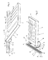
- a first embodiment of an inventive device is in the Fig. 1 to 12 shown.
- the device according to the invention comprises at least one bearing shell unit 1, which is designed for receiving items to be stored, such as tools.
- the bearing shell unit 1 preferably has compartments 2 in which the utensils to be stored can be inserted or used. This may, as shown by way of example, be subjects 2 adapted to the items to be accommodated. Also not specially adapted, for example, rectangular and / or square compartments 2 may be provided. Instead, the bearing shell unit 1 could also have only one depression, ie a single compartment, for receiving all utensils to be stored by the bearing shell unit 1.
- the bearing shell unit 1 comprises a shell body 3 having a bottom wall and side walls, in which a hard foam insert 4 is inserted, which has the compartments 2.
- the fan-forming deposits or inserts, z. B. from a plastic material be provided or the at least one compartment 2 could be formed directly from the shell body 3, without a further insert or another use would be present.
- An inventive Device may include one or more carrying units.
- a respective carrying unit 5 is attached directly or via at least one further intermediate part to a stationary part (for example a wall of a building, a piece of furniture or a machine or to a support frame) or to a movable carriage, a movable furniture or a movable machine.
- the attachment takes place for example by means of openings 6 (see. FIGS. 7 and 9 ) passing through screws (see. 4 to 6 ).
- a device according to the invention can also have a unit with a plurality of support units rigidly connected to one another, wherein the unit can be fastened to a stationary or movable part.
- the support unit 5 is formed in the embodiment shown as a profile rail, in particular in the form of an aluminum extruded profile. Other training is possible.
- the support unit 5 has a receiving groove 8, which extends continuously in the illustrated embodiment in the longitudinal direction of the rail.
- the receiving groove 8 runs horizontally in the assembled state of the support unit 5.
- the receiving groove 8 is bounded by (relative to the mounting state) upper and lower boundary walls 8a, 8b. These are formed here by an upper and a lower boundary web 9, 10, which protrude from a vertical base web 11. Other configurations of the receiving groove 8 are conceivable and possible.
- the bearing shell unit 1 has on a Einsteckseite lugs 12, 13, 14 for connecting the bearing shell unit 1 with the support unit 5 in different angular positions of the bearing shell unit 1.
- a bottom 15 of the bearing shell unit 1 in different from the horizontal inclined planes , wherein one of these planes is preferably horizontal (that is, has an inclination relative to the horizontal of 0 °).
- one of these planes is preferably horizontal (that is, has an inclination relative to the horizontal of 0 °).
- the illustrated embodiment be the possible inclination angles 0 °, 30 ° and 60 °, wherein at the inclination angles 30 ° and 60 °, the insertion side opposite side of the bearing shell unit is lower than the insertion side.
- angles of inclination could also be provided, in particular in the range of 0 ° to 90 °. Even angles of inclination, in which the side opposite the insertion side is higher than the insertion side, could be provided, for example in the range between 0 ° and 45 °.
- At least one lug 12, 13, 14 of the bearing shell unit 1 is provided for each inclination angle in which the bearing shell unit is connectable to the support unit 5.
- two lugs 12, 13, 14 are provided for each inclination angle.
- the lugs 12, 13, 14 at first and second connecting pieces 16, 17 are formed, which are fixed to the shell body 3, for example via a screw (screw holes are in the 10 to 12 shown).
- system webs 18, 19 of the respective connecting piece 16, 17 may be provided, which abut against the insertion-side side wall and on an adjoining portion of the bottom wall of the shell body 3.
- the connecting pieces 16, 17 may conveniently be formed of sections of, in particular in the form of hollow profiles, profile rails, preferably aluminum extruded profiles. These can be provided on both sides with covers to cover the inner cavity.
- a respective connecting piece 16, 17 has, corresponding to the desired angular positions in the connected to the support unit 5 state of the bearing shell unit 1, in different angularly extending directions extending lugs 12, 13, 14.
- the lugs 12, 13, 14 exhibiting connector could be provided. It would also be conceivable and possible to provide a shell body 3, on which noses 12, 13, 14 are formed directly (at least one per angular position).
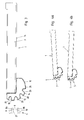
- a respective nose 12, 13, 14 has in the region of its free end a projection 20 which projects in the inserted into the receiving groove 8 state of the nose 12, 13, 14 upwards and connected to the support unit 5 state of the bearing shell unit 1 in a recess 21 protrudes in the upper boundary wall 8a of the receiving groove 8.
- the at least one nose 12, 13, 14 (in the exemplary embodiment two lugs) associated with the selected angular position of the bearing shell unit 1 is inserted into the receiving groove 8, namely from the open side of the receiving groove 8 opposite the groove base ago.
- the insertion of the respective at least one lug 12, 13, 14 takes place in a plug-in direction 22, which thus in the direction of the depth extent of the receiving groove 8 has (and not approximately in the direction of the longitudinal extension of the receiving groove 8).
- the at least one engaging in the receiving groove 8 nose 12, 13, 14 is pulled out in the insertion direction 22 opposite pull-out direction.
- the bearing shell unit 1 For inserting the at least one nose 12, 13, 14 in the receiving groove 8, the bearing shell unit 1 is tilted relative to the position which it assumes in the connected to the support unit 5 state, about a horizontal, parallel to the longitudinal extent of the receiving groove 8 axis and tilted this position straight in the insertion direction 22 with the at least one nose 12, 13, 14 inserted into the receiving groove 8.
- This position taken on insertion is in the Fig. 4a . 5a and 6a for the insertion of the various lugs 12, 13, 14 shown.
- the lower side of the respective lug 12, 13, 14 has a rounding 23, through which the cross section of the lug 12, 13, 14 in the direction of the free end of the nose 12, 13, 14 tapers.
- a rounding 23 and a bevel could be provided.
- the cross-sectional tapering formed by the rounding 23 or chamfer advantageously extends at least over one third of the total extension of the lug 12, 13, 14 relative to the insertion direction 22.
- the bearing shell unit After insertion of the respective at least one nose, the bearing shell unit is lowered with its side opposite the insertion side, d. H. about an axis lying in the receiving groove 8 horizontal, parallel to the receiving groove 8 extending axis tilts until the bearing shell unit 1 is held by the support unit 5 against further tilting form-fitting.
- the projection 20 protrudes into the recess 21, so that the bearing shell unit 1 is secured in a form-fitting manner against a straight pull in the pull-out direction 22 opposite withdrawal direction from the receiving groove 8 of the support unit 5.
- the connected to the support unit 5 state of the bearing shell unit 1 is for the various angular positions in the Fig. 4b . 5b and 6b shown.
- the bearing shell unit 1 connected to the carrying unit 5 and carried by the carrying unit 5 projects freely from the carrying unit.
- the at least one inserted into the receiving groove 8 nose 12, 13, 14 is supported with a contact area on the upper boundary wall 8a of the receiving groove 8.
- This contact area can be formed by the projection 20 or an area of the nose 12, 13, 14 adjacent to the projection 10.
- the nose rests on the lower boundary wall 8b with a support area located further away from the base of the groove. Instead, a lying outside the receiving groove 8 supporting region of the bearing shell unit 1, which is below the at least one protruding into the receiving groove 8 nose 12, 13, 14, frontally supported on the support unit 5, for example, at the free end of the lower boundary web 10th
- the bearing cup unit 1 inserted into the support unit 5 can be displaced in the longitudinal direction of the support unit 5, as shown in FIG Fig. 1 indicated by the double arrow 24.
- the Einsteckseite opposite side of the bearing shell unit 1 can be raised slightly for this purpose.
- a device according to the invention will comprise a plurality of support units 5, which are preferably arranged one above the other in the mounting position, and a plurality of bearing shell units 1.
- the bearing shell units 1 are formed identically at least in the respective connection region and the support units 5 are of identical design at least in the respective connection region. It can therefore be freely selected which of the bearing shell unit 1 is connected to which of the support unit 5.
- the connecting pieces 16, 17 have a groove 25 for insertion of a rubber strip 26, so that the bearing shell unit 1 in the region of the connecting pieces 16, 17 gently on a pad is turned off. In the region of the opposite side of the bearing shell unit 1 may also be provided on the bottom rubber elements for parking on a base on the bottom.
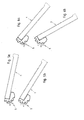
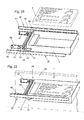
- a modified embodiment of the invention is in the Fig. 13 to 19 shown. Apart from the differences described below, the training corresponds to the basis of Fig. 1 to 12 described embodiment.
- the lugs 12, 13, 14 are provided in addition to the respectively projecting into the receiving groove 8 upwardly projecting projections 20 with downwardly projecting snap projections 27.
- the snap projections 27 are formed in the embodiment shown by end caps 28 which close the profile rail section 29 of the respective connecting piece 16, 17 on the front side. In Fig. 19 only one such end cap 28 is shown. Preferably, however, both ends of the profile rail portion 29 are closed by an end cap, wherein the end cap, not shown, is formed mirror-symmetrically to the end cap 28.
- the end caps together with the profiled rail section 29 form the respective connecting piece 16, 17.
- the end caps 28 are preferably made of plastic. In order to allow a resilient impressions of the snap projections 27, the end caps 28 in the snap projections 27 adjacent areas are preferably provided with openings 30.
- Snap-on projections 27 could also be formed in other ways, for example by a snap element which is displaceable against the force of a spring. Snap-on projections could also be formed directly on the profiled rail sections 29.
- FIGS. 20 and 21 show the formation of a pull-out guide by means of a bearing shell unit according to the invention.
- the rollers 33 rotatably mounted on this.
- the direction in which the rollers 33 are spaced, here is perpendicular to the insertion, in which the lugs 12, 13, 14 are inserted in the connection with a support unit 5 in the receiving groove 8.
- the bearing cup unit may be the same as in the embodiments described above.
- the rollers 33 may be rotatably mounted on the connecting pieces 16, 17, for example by axes of the rollers 33 in receiving openings 34 (see. Fig. 19 ) are inserted in the end caps 28.
- the rollers 33 can be used in first and second guide rails 35, 36.
- the bearing shell unit 1 from the at least one section between the guide rails 35, 36 is displaceable in the longitudinal direction of the guide rails 35, 36.
- a roller 37 in the region of the front end of the guide rail 35, 36 is rotatably mounted.
- the front end of the guide rail 35, 36 is the one from which the bearing shell unit 1 is supplied in its connection with the guide rails 35, 36.
- the bearing shell unit 1 connected to the guide rails 35, 36 rests with a respective catwalk 38 on the respective roller 37.
- the guide rails 35, 36 in cross-section C-shaped with upper and lower catwalks 39, 40, which are interconnected by a base web 41. Between the catwalks 39, 40, the respective roller 33 of the bearing shell unit 1 can roll.
- the upper catwalk 39 terminates at a distance from the front end of the respective guide rail 35, 36 or has a recess in the vicinity of this front end.
- a stop could be provided which limits the extraction of the bearing shell unit 1 at one point before the rollers 33 reach the released areas of the upper walkways 39, and which can be overcome by lifting the front end of the bearing shell unit 1.
- a piece of furniture may be equipped with one or more pairs of guide rails 35, 36, one or more To be able to use bearing shell units 1 simultaneously as drawers.
- Fig. 20 is only schematically indicated by a piece of furniture 50, a part of one of the side walls.
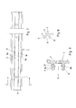
- FIGS. 22 and 23 Another possible embodiment for providing a pull-out is in the FIGS. 22 and 23 shown.
- a guide unit 42 is present, which has arranged on opposite sides, rotatably mounted rollers 43, 44.
- rollers 43, 44 are rotatably mounted on each side.
- the guide unit 42 is located between a first and a second guide rail 35, 36, wherein the rollers 43, 44 between upper and lower walkways 39, 40 of the guide rails 35, 36 can roll.
- the upper and lower walkways 39, 40 are interconnected by a base web 41, whereby a C-shaped configuration is present.
- the guide unit 42 further has a receiving groove 45, which has the same cross-sectional shape (cross-sectional contour) as the receiving groove 8 of the at least one support unit 5.
- the rollers 43, 44 are rotatably mounted on support rails 46, 47, which are interconnected by a rail 48 having the receiving groove 45.
- the support rails 46, 47 and the rail 48 are in this case at right angles to each other.
- the rail 48 has the same profile shape as the support unit 5.
- the bearing shell unit 1 is thus connected via their lugs 12, 13, 14 with the rail 48, preferably via the at least one nose 12, with a horizontal orientation of the bearing rail unit 1 connected to the rail 48 is achieved.
- the bearing shell unit 1 can be used as a drawer.
- a piece of furniture 50 may include one or more pairs of guide rails 35, 36, of which in each case a guide unit 42 is guided displaceably. With a respective guide unit 42, a bearing shell unit 1 can be connected, so that a corresponding number of drawers can be formed.
- the guide unit 42 in this case remains slidably mounted in the guide rails 35, 36, which remain connected to the furniture 50.
- the guide rails 35, 36 are immovably connected to the furniture 50.
- the guide rails 35, 36 are each connected to the furniture 50 via at least one further rail.
- first and second body rails could be fastened to the furniture 50, with respect to which the first and second guide rails 35, 36 are displaceably guided. In this way, full or excerpts can be realized.
- a piece of furniture 50 in the form of a tool cabinet can be formed.
- survey 8th receiving groove 32
- Einschnappverianaung 8a upper boundary wall
- caster 8b lower boundary wall 34
- receiving opening 9 upper boundary bar 35
- guide rail 10 lower boundary bar 36
- guide rail 11 base web 37
- caster 12 nose 38 catwalk 13 nose nose 39 upper catwalk 14 nose 40 lower catwalk 15 ground 41 base web 16 first connector 42
- caster 19 mooring facilities 45 20 head Start 46 rail 21 deepening 47 rail 22 insertion 48 rail 23 rounding off 50 Furniture 24 double arrow
Landscapes
- Engineering & Computer Science (AREA)
- Mechanical Engineering (AREA)
- Drawers Of Furniture (AREA)
- Warehouses Or Storage Devices (AREA)
- Supports Or Holders For Household Use (AREA)
Priority Applications (1)
| Application Number | Priority Date | Filing Date | Title |
|---|---|---|---|
| PL12783487T PL2765886T3 (pl) | 2011-10-13 | 2012-10-04 | Urządzenie do przechowywania przyborów |
Applications Claiming Priority (2)
| Application Number | Priority Date | Filing Date | Title |
|---|---|---|---|
| ATA1487/2011A AT512009B1 (de) | 2011-10-13 | 2011-10-13 | Einrichtung zum lagern von utensilien, insbesondere werkzeug |
| PCT/AT2012/000249 WO2013052975A1 (de) | 2011-10-13 | 2012-10-04 | Einrichtung zum lagern von utensilien |
Publications (2)
| Publication Number | Publication Date |
|---|---|
| EP2765886A1 EP2765886A1 (de) | 2014-08-20 |
| EP2765886B1 true EP2765886B1 (de) | 2016-01-13 |
Family
ID=47146122
Family Applications (1)
| Application Number | Title | Priority Date | Filing Date |
|---|---|---|---|
| EP12783487.7A Active EP2765886B1 (de) | 2011-10-13 | 2012-10-04 | Einrichtung zum lagern von utensilien |
Country Status (11)
| Country | Link |
|---|---|
| US (1) | US9247810B2 (ja) |
| EP (1) | EP2765886B1 (ja) |
| JP (1) | JP6259398B2 (ja) |
| CN (1) | CN103997934B (ja) |
| AT (1) | AT512009B1 (ja) |
| AU (1) | AU2012323804B2 (ja) |
| CA (1) | CA2851295A1 (ja) |
| DE (1) | DE202012012595U1 (ja) |
| ES (1) | ES2566070T3 (ja) |
| PL (1) | PL2765886T3 (ja) |
| WO (1) | WO2013052975A1 (ja) |
Families Citing this family (20)
| Publication number | Priority date | Publication date | Assignee | Title |
|---|---|---|---|---|
| US9142150B2 (en) * | 2012-04-10 | 2015-09-22 | Target Brands, Inc. | Sign holder assembly and associated method |
| DE102014005211A1 (de) | 2014-04-09 | 2015-10-15 | Oliver Horstmeyer | Flexibles Funktioneinrichtungselement |
| EP3078548B1 (en) | 2015-04-09 | 2018-08-29 | Modul-System HH AB | A storage system |
| DE102015206606A1 (de) * | 2015-04-14 | 2016-10-20 | Adolf Würth GmbH & Co. KG | Sortimentbox und Anordnung mit wenigstens einer Sortimentbox und einer Halteleiste |
| CN105415334B (zh) * | 2015-11-27 | 2017-05-31 | 河南新科起重机股份有限公司 | 一种起重机起升电机用成品齿轴摆放架 |
| US9878649B2 (en) * | 2016-02-01 | 2018-01-30 | Ranger Design | High density foldaway shelving |
| USD790926S1 (en) | 2016-04-28 | 2017-07-04 | Base4 Ventures, Llc | Grill trivet |
| CN106545557B (zh) * | 2016-11-28 | 2023-11-03 | 江苏隆基铝业有限公司 | 一种铝合金型材连接件 |
| CN106628501B (zh) * | 2016-11-29 | 2018-07-10 | 无锡特恒科技有限公司 | 防错托盘装置 |
| KR102467137B1 (ko) | 2017-06-15 | 2022-11-16 | 디퍼이 신테스 프로덕츠, 인코포레이티드 | 방사선 투과성 특징부를 갖는 sst 견인기 |
| CN107319766B (zh) * | 2017-06-30 | 2019-01-22 | 中山市翔实机械设备有限公司 | 一种可360度旋转的智能柜 |
| US10500713B2 (en) * | 2017-09-14 | 2019-12-10 | Black & Decker Inc. | Wall hanging system |
| US20190202230A1 (en) * | 2018-01-02 | 2019-07-04 | Studio Designs Inc. | Art supplies organization assembly |
| DE102018104809A1 (de) * | 2018-03-02 | 2019-09-05 | Rickard Nilsson | Fachboden und Fachbodenanordnung |
| DE102018110955A1 (de) * | 2018-05-08 | 2019-11-14 | Bystronic Laser Ag | Werkzeugaufbewahrungsvorrichtung für eine Werkzeugmaschine und Werkzeugmaschine |
| EP3666474A1 (de) * | 2018-12-12 | 2020-06-17 | Hilti Aktiengesellschaft | Aufnahmevorrichtung für eine elektronikeinrichtung und baugruppe |
| SE543492C2 (en) * | 2019-02-06 | 2021-03-09 | Ikea Supply Ag | A drawer sliding system |
| GB2584477B (en) * | 2019-06-06 | 2021-09-22 | Keymed Medical & Industrial Equipment Ltd | Mounting system for a medical workstation |
| JP2021144187A (ja) * | 2020-03-13 | 2021-09-24 | ヤマハ株式会社 | 楽器および鍵盤楽器 |
| LU500933B1 (de) | 2021-11-30 | 2023-06-02 | Better Basics Laborbedarf Gmbh | Klemmschlittenschienenhalterungsvorrichtung |
Family Cites Families (55)
| Publication number | Priority date | Publication date | Assignee | Title |
|---|---|---|---|---|
| NL107523C (ja) * | 1959-04-28 | |||
| US3093094A (en) * | 1962-01-17 | 1963-06-11 | Muammer A Oztekin | Adjustable shelf support |
| NL6704277A (ja) * | 1966-03-28 | 1967-09-29 | ||
| US3463433A (en) * | 1967-08-08 | 1969-08-26 | Grant Pulley & Hardware Corp | Adjustable bracket |
| US3550891A (en) * | 1968-12-04 | 1970-12-29 | Charles F Scott | Adjustable shelf bracket |
| GB1222488A (en) * | 1969-09-11 | 1971-02-17 | Basil Zachariou | Improvements in shelving assemblies |
| US3700114A (en) * | 1971-01-18 | 1972-10-24 | Clark Equipment Co | Adjustable shelf support bracket |
| US3795379A (en) * | 1972-09-13 | 1974-03-05 | Ebsco Ind Inc | Adjustable shelf support |
| US4008873A (en) * | 1976-01-29 | 1977-02-22 | Emhart Industries, Inc. | Angularly adjustable shelf bracket |
| CA1043298A (en) * | 1976-11-16 | 1978-11-28 | J. A. Wilson Display Limited | Display structure |
| US4228906A (en) * | 1978-09-14 | 1980-10-21 | Kardex Systems, Inc. | Adjustable rail mounting assembly |
| US4307671A (en) * | 1980-05-05 | 1981-12-29 | The Kent Corporation | Merchandise shelving display |
| US4609173A (en) * | 1984-10-01 | 1986-09-02 | Martin-Paul, Inc. | Magnetically attachable towel hanger |
| DE8518079U1 (de) | 1985-06-21 | 1985-08-29 | Bosch-Siemens Hausgeräte GmbH, 8000 München | Hängekasten |
| SE457631B (sv) * | 1987-06-02 | 1989-01-16 | Btj Produkter Ab | Foervaringssystem saerskilt foer tidskrifter och dylikt |
| JPH0725064Y2 (ja) * | 1987-07-24 | 1995-06-07 | 株式会社岡村製作所 | 棚板支持装置 |
| US4869378A (en) * | 1988-08-29 | 1989-09-26 | Hospital Systems, Inc. | Mounting rail for hospital appliances and bracket |
| JPH0382178U (ja) * | 1989-12-15 | 1991-08-21 | ||
| US5169221A (en) * | 1990-09-04 | 1992-12-08 | General Devices Co., Inc. | Pivotable drawer slide mount with pivot controlling guide slot |
| US5117986A (en) * | 1991-04-19 | 1992-06-02 | Lin Hsin Hsiung | Shelf with height and angle adjustment |
| CN2098844U (zh) * | 1991-09-11 | 1992-03-18 | 张弘毅 | 可随意调整悬挂角度的框架 |
| US5275281A (en) | 1992-07-17 | 1994-01-04 | Ebeling Keith R | Micrometer organizing and protecting device |
| NZ248219A (en) * | 1992-07-22 | 1995-06-27 | Rene Wilhelm Crooymans | Shelving support system; column supports with discrete cutouts for extrusions that support a shelf |
| US5244272A (en) * | 1992-11-02 | 1993-09-14 | Thompson Donn K | Space-saving undercabinet spice jar drawer |
| US5259519A (en) * | 1993-01-11 | 1993-11-09 | Lieberman William B | Advertiser and hygienic disposable toothbrush holder |
| DE9301716U1 (ja) * | 1993-02-08 | 1993-05-19 | Huang, Che-Hsiung, Taipeh/T'ai-Pei, Tw | |
| US5452875A (en) * | 1994-04-21 | 1995-09-26 | Discovery Plastics, Inc. | Plastic support assembly |
| GB2297896A (en) * | 1995-02-02 | 1996-08-21 | Artform Int Ltd | Tiltable shelf |
| DE19646531A1 (de) | 1996-10-29 | 1998-06-10 | Wilfried Poellet | Utensilienträger |
| US5960965A (en) * | 1996-11-12 | 1999-10-05 | Saunders; Todd R. | Product display system |
| KR100245626B1 (ko) * | 1997-06-30 | 2000-02-15 | 강병호 | 휴대용 컴퓨터의 키보드 틸팅장치 |
| US5941026A (en) * | 1998-01-20 | 1999-08-24 | Storewall Llc | Slatwall display system |
| TW404638U (en) * | 1999-03-18 | 2000-09-01 | Chiou Huei Min | Plane monitor used foot seat |
| CN2371868Y (zh) * | 1999-03-31 | 2000-04-05 | 三豪有限公司 | 拖轨式收折机构 |
| CN2413791Y (zh) * | 1999-04-08 | 2001-01-10 | 北京华信文化发展有限责任公司 | 一种科学实验箱 |
| AU5895599A (en) * | 1999-08-12 | 2001-03-13 | Furn Li Lee | A storage system |
| US6487979B2 (en) * | 2000-03-15 | 2002-12-03 | Utilimaster | Stowable shelf assembly |
| DE10153621A1 (de) | 2001-10-31 | 2003-05-22 | Bsh Bosch Siemens Hausgeraete | Kältegerät mit verstellbaren Fachböden |
| US6648390B1 (en) | 2002-05-21 | 2003-11-18 | Global Industries Holdings Ltd. | Single-stack tool rack |
| DE20314773U1 (de) * | 2003-09-22 | 2003-12-04 | Elabo Gmbh | Leiste zum Anbringen von Lagerelementen |
| US7140703B1 (en) * | 2004-09-14 | 2006-11-28 | Holdgate Iii Edward | Pull-out and tilt guide assembly for a drawer |
| TWI263571B (en) * | 2004-10-26 | 2006-10-11 | Global Ind Holdings Ltd | Hand tool storage stand |
| NO323380B1 (no) | 2004-11-29 | 2007-04-16 | Ebeco As | Anordning ved hjulgaende reol |
| DE202004020115U1 (de) * | 2004-12-29 | 2006-05-11 | Liebherr-Hausgeräte Ochsenhausen GmbH | Kühlgerät |
| GB2423790A (en) | 2005-03-03 | 2006-09-06 | Tung Chieh Ind Co Ltd | A locking control unit for tool box drawers |
| US7527156B2 (en) * | 2005-07-12 | 2009-05-05 | Whirlpool Corporation | Tool caddy |
| US20070017886A1 (en) * | 2005-07-20 | 2007-01-25 | Jui-Chien Kao | Suspension display rack |
| US20070278168A1 (en) * | 2006-05-11 | 2007-12-06 | Li Wayne K | Decorative wall hanging assembly |
| US8550265B2 (en) | 2007-01-31 | 2013-10-08 | Kirk J. Botkin | Support systems and components for same |
| JP3132743U (ja) * | 2007-03-26 | 2007-06-21 | 法明 西本 | 傾斜可能な棚板を備えた棚装置 |
| US20090161309A1 (en) * | 2007-12-21 | 2009-06-25 | Ching Lun Yang | Removable hard drive casing |
| RU2488051C2 (ru) * | 2008-11-11 | 2013-07-20 | Бсх Бош Унд Сименис Хаусгерете Гмбх | Холодильный аппарат с регулируемой по высоте полкой для охлаждаемых продуктов |
| US8136775B2 (en) * | 2009-06-30 | 2012-03-20 | Vance Chiang | Rack assembly |
| JP3166150U (ja) * | 2010-10-03 | 2011-02-24 | 信一 小屋野 | 整理整頓トレー |
| US8882065B2 (en) * | 2011-04-26 | 2014-11-11 | Kimball International, Inc. | Two piece track assembly |
-
2011
- 2011-10-13 AT ATA1487/2011A patent/AT512009B1/de active
-
2012
- 2012-10-04 JP JP2014534868A patent/JP6259398B2/ja active Active
- 2012-10-04 EP EP12783487.7A patent/EP2765886B1/de active Active
- 2012-10-04 CA CA2851295A patent/CA2851295A1/en not_active Abandoned
- 2012-10-04 US US14/350,430 patent/US9247810B2/en active Active
- 2012-10-04 DE DE202012012595U patent/DE202012012595U1/de not_active Expired - Lifetime
- 2012-10-04 ES ES12783487.7T patent/ES2566070T3/es active Active
- 2012-10-04 AU AU2012323804A patent/AU2012323804B2/en active Active
- 2012-10-04 WO PCT/AT2012/000249 patent/WO2013052975A1/de active Application Filing
- 2012-10-04 PL PL12783487T patent/PL2765886T3/pl unknown
- 2012-10-04 CN CN201280050138.1A patent/CN103997934B/zh active Active
Also Published As
| Publication number | Publication date |
|---|---|
| AT512009A1 (de) | 2013-04-15 |
| AU2012323804B2 (en) | 2016-10-27 |
| CN103997934A (zh) | 2014-08-20 |
| CA2851295A1 (en) | 2013-04-18 |
| AU2012323804A1 (en) | 2014-04-24 |
| DE202012012595U1 (de) | 2013-07-05 |
| WO2013052975A1 (de) | 2013-04-18 |
| AT512009B1 (de) | 2014-04-15 |
| ES2566070T3 (es) | 2016-04-08 |
| CN103997934B (zh) | 2017-04-05 |
| US20140265789A1 (en) | 2014-09-18 |
| JP2014531947A (ja) | 2014-12-04 |
| US9247810B2 (en) | 2016-02-02 |
| EP2765886A1 (de) | 2014-08-20 |
| JP6259398B2 (ja) | 2018-01-10 |
| PL2765886T3 (pl) | 2016-07-29 |
Similar Documents
| Publication | Publication Date | Title |
|---|---|---|
| EP2765886B1 (de) | Einrichtung zum lagern von utensilien | |
| WO2008095766A2 (de) | Haushaltsgerät mit trägersystem | |
| EP1929224B1 (de) | Kältegerät mit geteilter abstellplatte | |
| EP2907470B1 (de) | Gerätewagen | |
| AT512008B1 (de) | Einrichtung zum lagern von utensilien, insbesondere werkzeug | |
| EP2844108B1 (de) | Haltevorrichtung für ein tragelement eines schrankes sowie kühl-, gefrierschrank oder weinlagerungsschrank | |
| DE102007059204A1 (de) | Schaltschrank oder Rack | |
| WO2008122515A2 (de) | Kühlgutabsteller und damit ausgestattetes kältegerät | |
| DE8018254U1 (de) | Sortimentskastenregal | |
| DE2431462C2 (de) | Unterteilungsorgan für Schubkästen | |
| EP0063805A2 (de) | Regal zur Lagerung und Bereitstellung von Gegenständen | |
| EP1984686A2 (de) | Kältegerät und fachboden dafür | |
| EP2353444B1 (de) | Schrankauszug | |
| WO2011006765A2 (de) | Kühlgutträger für ein kältegerät | |
| DE102009046027A1 (de) | Kältegerät und Kühlgutträger mit unterteilter Abstellplatte | |
| DE3537335C2 (ja) | ||
| DE202006014590U1 (de) | Schubladenteiler | |
| DE3129573C2 (de) | Bausatz für Möbel, insbesondere Anbaumöbel | |
| WO1992006627A1 (de) | Buchablage für ein tragstützensystem | |
| EP2327332A1 (de) | Regalsystem | |
| WO2018028844A1 (de) | Profilbauteil und möbelsystem mit einem solchen profilbauteil | |
| CH681287A5 (en) | Support for suspended file holders | |
| DE1907776A1 (de) | Anzeigetafel,insbesondere fuer Planungszwecke | |
| DE1654628A1 (de) | Moebelbausatz | |
| DE3645007C2 (ja) |
Legal Events
| Date | Code | Title | Description |
|---|---|---|---|
| PUAI | Public reference made under article 153(3) epc to a published international application that has entered the european phase |
Free format text: ORIGINAL CODE: 0009012 |
|
| 17P | Request for examination filed |
Effective date: 20140307 |
|
| AK | Designated contracting states |
Kind code of ref document: A1 Designated state(s): AL AT BE BG CH CY CZ DE DK EE ES FI FR GB GR HR HU IE IS IT LI LT LU LV MC MK MT NL NO PL PT RO RS SE SI SK SM TR |
|
| RAP1 | Party data changed (applicant data changed or rights of an application transferred) |
Owner name: METZLER GMBH & CO KG |
|
| DAX | Request for extension of the european patent (deleted) | ||
| GRAP | Despatch of communication of intention to grant a patent |
Free format text: ORIGINAL CODE: EPIDOSNIGR1 |
|
| INTG | Intention to grant announced |
Effective date: 20150812 |
|
| GRAS | Grant fee paid |
Free format text: ORIGINAL CODE: EPIDOSNIGR3 |
|
| GRAA | (expected) grant |
Free format text: ORIGINAL CODE: 0009210 |
|
| AK | Designated contracting states |
Kind code of ref document: B1 Designated state(s): AL AT BE BG CH CY CZ DE DK EE ES FI FR GB GR HR HU IE IS IT LI LT LU LV MC MK MT NL NO PL PT RO RS SE SI SK SM TR |
|
| REG | Reference to a national code |
Ref country code: GB Ref legal event code: FG4D Free format text: NOT ENGLISH |
|
| REG | Reference to a national code |
Ref country code: CH Ref legal event code: EP |
|
| REG | Reference to a national code |
Ref country code: IE Ref legal event code: FG4D Free format text: LANGUAGE OF EP DOCUMENT: GERMAN |
|
| REG | Reference to a national code |
Ref country code: AT Ref legal event code: REF Ref document number: 769907 Country of ref document: AT Kind code of ref document: T Effective date: 20160215 |
|
| REG | Reference to a national code |
Ref country code: DE Ref legal event code: R096 Ref document number: 502012005739 Country of ref document: DE |
|
| REG | Reference to a national code |
Ref country code: CH Ref legal event code: NV Representative=s name: SCHNEIDER FELDMANN AG PATENT- UND MARKENANWAEL, CH |
|
| REG | Reference to a national code |
Ref country code: SE Ref legal event code: TRGR |
|
| REG | Reference to a national code |
Ref country code: ES Ref legal event code: FG2A Ref document number: 2566070 Country of ref document: ES Kind code of ref document: T3 Effective date: 20160408 |
|
| REG | Reference to a national code |
Ref country code: NL Ref legal event code: FP |
|
| REG | Reference to a national code |
Ref country code: LT Ref legal event code: MG4D |
|
| REG | Reference to a national code |
Ref country code: NO Ref legal event code: T2 Effective date: 20160113 |
|
| PG25 | Lapsed in a contracting state [announced via postgrant information from national office to epo] |
Ref country code: GR Free format text: LAPSE BECAUSE OF FAILURE TO SUBMIT A TRANSLATION OF THE DESCRIPTION OR TO PAY THE FEE WITHIN THE PRESCRIBED TIME-LIMIT Effective date: 20160414 Ref country code: HR Free format text: LAPSE BECAUSE OF FAILURE TO SUBMIT A TRANSLATION OF THE DESCRIPTION OR TO PAY THE FEE WITHIN THE PRESCRIBED TIME-LIMIT Effective date: 20160113 |
|
| PG25 | Lapsed in a contracting state [announced via postgrant information from national office to epo] |
Ref country code: RS Free format text: LAPSE BECAUSE OF FAILURE TO SUBMIT A TRANSLATION OF THE DESCRIPTION OR TO PAY THE FEE WITHIN THE PRESCRIBED TIME-LIMIT Effective date: 20160113 Ref country code: LT Free format text: LAPSE BECAUSE OF FAILURE TO SUBMIT A TRANSLATION OF THE DESCRIPTION OR TO PAY THE FEE WITHIN THE PRESCRIBED TIME-LIMIT Effective date: 20160113 Ref country code: PT Free format text: LAPSE BECAUSE OF FAILURE TO SUBMIT A TRANSLATION OF THE DESCRIPTION OR TO PAY THE FEE WITHIN THE PRESCRIBED TIME-LIMIT Effective date: 20160513 Ref country code: IS Free format text: LAPSE BECAUSE OF FAILURE TO SUBMIT A TRANSLATION OF THE DESCRIPTION OR TO PAY THE FEE WITHIN THE PRESCRIBED TIME-LIMIT Effective date: 20160513 Ref country code: LV Free format text: LAPSE BECAUSE OF FAILURE TO SUBMIT A TRANSLATION OF THE DESCRIPTION OR TO PAY THE FEE WITHIN THE PRESCRIBED TIME-LIMIT Effective date: 20160113 |
|
| REG | Reference to a national code |
Ref country code: DE Ref legal event code: R097 Ref document number: 502012005739 Country of ref document: DE |
|
| PG25 | Lapsed in a contracting state [announced via postgrant information from national office to epo] |
Ref country code: EE Free format text: LAPSE BECAUSE OF FAILURE TO SUBMIT A TRANSLATION OF THE DESCRIPTION OR TO PAY THE FEE WITHIN THE PRESCRIBED TIME-LIMIT Effective date: 20160113 Ref country code: DK Free format text: LAPSE BECAUSE OF FAILURE TO SUBMIT A TRANSLATION OF THE DESCRIPTION OR TO PAY THE FEE WITHIN THE PRESCRIBED TIME-LIMIT Effective date: 20160113 |
|
| REG | Reference to a national code |
Ref country code: FR Ref legal event code: PLFP Year of fee payment: 5 |
|
| PLBE | No opposition filed within time limit |
Free format text: ORIGINAL CODE: 0009261 |
|
| STAA | Information on the status of an ep patent application or granted ep patent |
Free format text: STATUS: NO OPPOSITION FILED WITHIN TIME LIMIT |
|
| PG25 | Lapsed in a contracting state [announced via postgrant information from national office to epo] |
Ref country code: SK Free format text: LAPSE BECAUSE OF FAILURE TO SUBMIT A TRANSLATION OF THE DESCRIPTION OR TO PAY THE FEE WITHIN THE PRESCRIBED TIME-LIMIT Effective date: 20160113 Ref country code: RO Free format text: LAPSE BECAUSE OF FAILURE TO SUBMIT A TRANSLATION OF THE DESCRIPTION OR TO PAY THE FEE WITHIN THE PRESCRIBED TIME-LIMIT Effective date: 20160113 Ref country code: SM Free format text: LAPSE BECAUSE OF FAILURE TO SUBMIT A TRANSLATION OF THE DESCRIPTION OR TO PAY THE FEE WITHIN THE PRESCRIBED TIME-LIMIT Effective date: 20160113 |
|
| 26N | No opposition filed |
Effective date: 20161014 |
|
| PG25 | Lapsed in a contracting state [announced via postgrant information from national office to epo] |
Ref country code: BG Free format text: LAPSE BECAUSE OF FAILURE TO SUBMIT A TRANSLATION OF THE DESCRIPTION OR TO PAY THE FEE WITHIN THE PRESCRIBED TIME-LIMIT Effective date: 20160413 Ref country code: SI Free format text: LAPSE BECAUSE OF FAILURE TO SUBMIT A TRANSLATION OF THE DESCRIPTION OR TO PAY THE FEE WITHIN THE PRESCRIBED TIME-LIMIT Effective date: 20160113 |
|
| PG25 | Lapsed in a contracting state [announced via postgrant information from national office to epo] |
Ref country code: LU Free format text: LAPSE BECAUSE OF NON-PAYMENT OF DUE FEES Effective date: 20161004 |
|
| REG | Reference to a national code |
Ref country code: FR Ref legal event code: PLFP Year of fee payment: 6 |
|
| PG25 | Lapsed in a contracting state [announced via postgrant information from national office to epo] |
Ref country code: HU Free format text: LAPSE BECAUSE OF FAILURE TO SUBMIT A TRANSLATION OF THE DESCRIPTION OR TO PAY THE FEE WITHIN THE PRESCRIBED TIME-LIMIT; INVALID AB INITIO Effective date: 20121004 |
|
| PG25 | Lapsed in a contracting state [announced via postgrant information from national office to epo] |
Ref country code: MC Free format text: LAPSE BECAUSE OF FAILURE TO SUBMIT A TRANSLATION OF THE DESCRIPTION OR TO PAY THE FEE WITHIN THE PRESCRIBED TIME-LIMIT Effective date: 20160113 Ref country code: MK Free format text: LAPSE BECAUSE OF FAILURE TO SUBMIT A TRANSLATION OF THE DESCRIPTION OR TO PAY THE FEE WITHIN THE PRESCRIBED TIME-LIMIT Effective date: 20160113 Ref country code: CY Free format text: LAPSE BECAUSE OF FAILURE TO SUBMIT A TRANSLATION OF THE DESCRIPTION OR TO PAY THE FEE WITHIN THE PRESCRIBED TIME-LIMIT Effective date: 20160113 Ref country code: MT Free format text: LAPSE BECAUSE OF FAILURE TO SUBMIT A TRANSLATION OF THE DESCRIPTION OR TO PAY THE FEE WITHIN THE PRESCRIBED TIME-LIMIT Effective date: 20160113 |
|
| REG | Reference to a national code |
Ref country code: FR Ref legal event code: PLFP Year of fee payment: 7 |
|
| PG25 | Lapsed in a contracting state [announced via postgrant information from national office to epo] |
Ref country code: AL Free format text: LAPSE BECAUSE OF FAILURE TO SUBMIT A TRANSLATION OF THE DESCRIPTION OR TO PAY THE FEE WITHIN THE PRESCRIBED TIME-LIMIT Effective date: 20160113 |
|
| REG | Reference to a national code |
Ref country code: CH Ref legal event code: PFA Owner name: METZLER GMBH AND CO KG, AT Free format text: FORMER OWNER: METZLER GMBH AND CO KG, AT |
|
| PGFP | Annual fee paid to national office [announced via postgrant information from national office to epo] |
Ref country code: TR Payment date: 20230920 Year of fee payment: 12 |
|
| PGFP | Annual fee paid to national office [announced via postgrant information from national office to epo] |
Ref country code: PL Payment date: 20230921 Year of fee payment: 12 Ref country code: NL Payment date: 20231026 Year of fee payment: 12 |
|
| PGFP | Annual fee paid to national office [announced via postgrant information from national office to epo] |
Ref country code: GB Payment date: 20231024 Year of fee payment: 12 |
|
| PGFP | Annual fee paid to national office [announced via postgrant information from national office to epo] |
Ref country code: ES Payment date: 20231110 Year of fee payment: 12 |
|
| PGFP | Annual fee paid to national office [announced via postgrant information from national office to epo] |
Ref country code: SE Payment date: 20231023 Year of fee payment: 12 Ref country code: NO Payment date: 20231018 Year of fee payment: 12 Ref country code: IT Payment date: 20231024 Year of fee payment: 12 Ref country code: IE Payment date: 20231018 Year of fee payment: 12 Ref country code: FR Payment date: 20231026 Year of fee payment: 12 Ref country code: FI Payment date: 20231026 Year of fee payment: 12 Ref country code: DE Payment date: 20231027 Year of fee payment: 12 Ref country code: CZ Payment date: 20231003 Year of fee payment: 12 Ref country code: CH Payment date: 20231102 Year of fee payment: 12 Ref country code: AT Payment date: 20231017 Year of fee payment: 12 |
|
| PGFP | Annual fee paid to national office [announced via postgrant information from national office to epo] |
Ref country code: BE Payment date: 20231026 Year of fee payment: 12 |