EP2765886B1 - Device for storing utensils, especially tools - Google Patents
Device for storing utensils, especially tools Download PDFInfo
- Publication number
- EP2765886B1 EP2765886B1 EP12783487.7A EP12783487A EP2765886B1 EP 2765886 B1 EP2765886 B1 EP 2765886B1 EP 12783487 A EP12783487 A EP 12783487A EP 2765886 B1 EP2765886 B1 EP 2765886B1
- Authority
- EP
- European Patent Office
- Prior art keywords
- unit
- storage
- receiving groove
- bearing shell
- tray unit
- Prior art date
- Legal status (The legal status is an assumption and is not a legal conclusion. Google has not performed a legal analysis and makes no representation as to the accuracy of the status listed.)
- Active
Links
- 210000001331 nose Anatomy 0.000 claims description 50
- 238000003780 insertion Methods 0.000 claims description 24
- 230000037431 insertion Effects 0.000 claims description 24
- 239000006260 foam Substances 0.000 claims description 3
- 239000004033 plastic Substances 0.000 description 4
- 229910052782 aluminium Inorganic materials 0.000 description 2
- XAGFODPZIPBFFR-UHFFFAOYSA-N aluminium Chemical class [Al] XAGFODPZIPBFFR-UHFFFAOYSA-N 0.000 description 2
- 239000000463 material Substances 0.000 description 2
- 238000004873 anchoring Methods 0.000 description 1
- 230000015572 biosynthetic process Effects 0.000 description 1
- 239000000969 carrier Substances 0.000 description 1
- 150000001875 compounds Chemical class 0.000 description 1
- 230000001747 exhibiting effect Effects 0.000 description 1
- 238000000605 extraction Methods 0.000 description 1
- 210000003128 head Anatomy 0.000 description 1
- 238000007689 inspection Methods 0.000 description 1
- 229910052751 metal Inorganic materials 0.000 description 1
- 239000002184 metal Substances 0.000 description 1
- 238000002360 preparation method Methods 0.000 description 1
Images


Classifications
-
- A—HUMAN NECESSITIES
- A47—FURNITURE; DOMESTIC ARTICLES OR APPLIANCES; COFFEE MILLS; SPICE MILLS; SUCTION CLEANERS IN GENERAL
- A47B—TABLES; DESKS; OFFICE FURNITURE; CABINETS; DRAWERS; GENERAL DETAILS OF FURNITURE
- A47B57/00—Cabinets, racks or shelf units, characterised by features for adjusting shelves or partitions
- A47B57/04—Cabinets, racks or shelf units, characterised by features for adjusting shelves or partitions with means for adjusting the inclination of the shelves
- A47B57/045—Cantilever shelves
-
- A—HUMAN NECESSITIES
- A47—FURNITURE; DOMESTIC ARTICLES OR APPLIANCES; COFFEE MILLS; SPICE MILLS; SUCTION CLEANERS IN GENERAL
- A47B—TABLES; DESKS; OFFICE FURNITURE; CABINETS; DRAWERS; GENERAL DETAILS OF FURNITURE
- A47B88/00—Drawers for tables, cabinets or like furniture; Guides for drawers
- A47B88/40—Sliding drawers; Slides or guides therefor
- A47B88/423—Fastening devices for slides or guides
- A47B88/427—Fastening devices for slides or guides at drawer side
-
- B—PERFORMING OPERATIONS; TRANSPORTING
- B25—HAND TOOLS; PORTABLE POWER-DRIVEN TOOLS; MANIPULATORS
- B25H—WORKSHOP EQUIPMENT, e.g. FOR MARKING-OUT WORK; STORAGE MEANS FOR WORKSHOPS
- B25H3/00—Storage means or arrangements for workshops facilitating access to, or handling of, work tools or instruments
- B25H3/06—Trays
Landscapes
- Engineering & Computer Science (AREA)
- Mechanical Engineering (AREA)
- Drawers Of Furniture (AREA)
- Warehouses Or Storage Devices (AREA)
- Supports Or Holders For Household Use (AREA)
Description
Die Erfindung bezieht sich auf eine Einrichtung zum Lagern von Utensilien, insbesondere Werkzeug, welche mindestens eine Lagerschaleneinheit zum Aufnehmen von zu lagernden Utensilien und mindestens eine Trageinheit umfasst, mit der die Lagerschaleneinheit zum Tragen der Lagerschaleneinheit verbindbar und von der die Lagerschaleneinheit abnehmbar ist, wobei die Lagerschaleneinheit Nasen aufweist, die zum Verbinden der Lagerschaleneinheit mit der Trageinheit in eine Aufnahmenut der Trageinheit einsetzbar sind, und wobei die mit der Trageinheit verbundene Lagerschaleneinheit von der Trageinheit auskragt und mindestens eine Lagerschaleneinheit in mindestens zwei unterschiedlichen Winkelstellungen bezogen auf eine horizontale Achse mit der Trageinheit verbindbar ist und zum Verbinden der Lagerschaleneinheit mit der Trageinheit in verschiedenen Winkelstellungen unterschiedliche Nasen der Lagerschaleneinheit in die Aufnahmenut der Trageinheit einsetzbar sind.The invention relates to a device for storing utensils, in particular tool, which comprises at least one bearing shell unit for receiving items to be stored and at least one support unit with which the bearing shell unit for supporting the bearing shell unit connectable and from which the bearing shell unit is removable, wherein the Bearing unit has lugs which are used to connect the bearing shell unit with the support unit in a receiving groove of the support unit, and wherein the bearing unit connected to the support unit protrudes from the support unit and at least one bearing shell unit in at least two different angular positions with respect to a horizontal axis connected to the support unit is and for connecting the bearing cup unit with the support unit in different angular positions different lugs of the bearing shell unit can be inserted into the receiving groove of the support unit.
Bekannt sind Werkzeugschränke, deren Schubladen mit Facheinteilungen versehen sind. Zur Verwendung eines Werkzeugs muss die entsprechende Schublade aufgezogen werden und das Werkzeug herausgenommen und später wieder in das entsprechende Fach eingeräumt werden. Sollen die Werkzeuge an einem entfernten Einsatzort eingesetzt werden, so müssen die benötigten Werkzeuge aus dem Werkzeugschrank entnommen und später wieder in die vorgesehenen Fächer eingeräumt werden. Es ist somit mühsam, ein vorgegebenes Ordnungssystem aufrechtzuerhalten.Are known tool cabinets whose drawers are provided with compartmentalisations. To use a tool, the appropriate drawer must be opened and the tool removed and later re-added to the appropriate compartment. If the tools are to be used at a remote location, the required tools must be removed from the tool cabinet and later returned to the compartments provided. It is thus troublesome to maintain a predetermined order system.
Es ist auch bekannt, Hartschaumeinlagen, in denen den aufzunehmenden Werkzeugen genau angepasste Ausnehmungen vorgesehen sind, welche an die jeweiligen Werkzeuge angepasste Fächer bilden, mit den darin eingesetzten Werkzeugen in Schubladen von Werkzeugschränken abzulegen, sodass die Hartschaumeinlagen mit den darin aufgenommenen Werkzeugen bei Bedarf herausgenommen und zum Einsatzort gebracht werden können. Eine solche Handhabung ist aber ebenfalls relativ umständlich. Weiters bekannt sind Metall-Schalen mit Einsätzen aus Kunststoffmaterialien, welche Fächer zum Aufnehmen von Werkzeugen aufweisen.It is also known hard foam inserts in which the male tools are provided precisely adapted recesses, which form adapted to the respective tools compartments to place with the tools inserted in drawers of tool cabinets, so that the Hartschaumeinlagen with the tools housed in it can be removed if necessary and brought to the place of use. However, such handling is also relatively cumbersome. Also known are metal trays with inserts of plastic materials having trays for receiving tools.
Bei der aus der
Aus der
Die
Aus der
Aus der
Aufgabe der Erfindung ist es, eine Einrichtung der eingangs genannten Art bereitzustellen, die bei einer einfachen Ausbildung eine vorteilhafte Handhabung der mindestens einen Lagerschaleneinheit ermöglicht und bei der die Zugänglichkeit oder die Präsentation des Inhalts der Lagerschaleneinheit für unterschiedliche Situationen optimiert werden kann. Erfindungsgemäß gelingt dies durch eine Einrichtung mit den Merkmalen des Anspruchs 1.The object of the invention is to provide a device of the type mentioned, which allows for a simple design advantageous handling of at least one bearing shell unit and in which the accessibility or the presentation of the contents of the bearing shell unit can be optimized for different situations. According to the invention, this is achieved by a device having the features of
Bei der Einrichtung gemäß der Erfindung weist eine jeweilige Lagerschaleneinheit Nasen auf, die zum Verbinden der Lagerschaleneinheit mit der Trageinheit bzw. einer der Trageinheiten in eine Aufnahmenut der Trageinheit einsetz-bar ist. Die mit der Trageinheit verbundene Lagerschaleneinheit kragt hierbei von der Trageinheit ab. Die Seite der Lagerschaleneinheit, die der die Nasen aufweisenden Seite der Lagerschaleneinheit gegenüber liegt (also die von der Trageinheit abgewandte Seite der Lagerschaleneinheit), ist somit im mit der Trageinheit verbundenen Zustand der Lagerschaleneinheit frei. Vorteilhafterweise stützt eine jeweilige in die Aufnahmenut eingesetzte Nase der Lagerschaleneinheit die Lagerschaleneinheit gegen eine Verkippung ab, bei der sich die freie Seite der Lagerschaleneinheit nach unten bewegen würde. Hierzu stützt sich die Nase mit einem Anlagebereich an der oberen Begrenzungswand der Aufnahmenut ab. Weiters liegt die Nase mit einem weiter außen liegenden (d. h. weniger tief in der Nut liegenden) Auflagebereich auf der unteren Begrenzungswand der Aufnahmenut auf oder ein außerhalb der Aufnahmenut liegender Abstützbereich der Lagerschaleneinheit stützt sich im Bereich unterhalb der Aufnahmenut stirnseitig an der Trageinheit ab.In the device according to the invention, a respective bearing shell unit has lugs which can be inserted into a receiving groove of the support unit for connecting the bearing shell unit to the support unit or one of the support units. The bearing shell unit connected to the support unit projects from the support unit. The side of the bearing shell unit which lies opposite the side of the bearing shell unit having the lugs (ie the side of the bearing shell unit facing away from the support unit) is thus free in the state of the bearing shell unit connected to the support unit. Advantageously, a respective inserted into the receiving groove nose of the bearing shell unit supports the bearing shell unit against tilting, in which the free side of the bearing shell unit would move down. For this purpose, the nose is supported by a contact area on the upper boundary wall of the receiving groove. Furthermore, the nose lies with a further outward (ie less deeply in the groove lying) support area on the lower boundary wall of the receiving groove on or outside the receiving groove lying support region of the bearing shell unit is supported in the area below the receiving groove frontally on the support unit.
Die Lagerschaleneinheit ist also werkzeuglos mit der Trageinheit verbindbar bzw. von dieser abnehmbar.The bearing shell unit is thus tool-free connectable to the support unit or removable from this.
In einer vorteilhaften Ausführungsform der Erfindung wird die Verbindung zwischen der Lagerschaleneinheit und der Trageinheit nur durch die mindestens eine im die Aufnahmenut eingesetzte Nase, gegebenenfalls zusammen mit dem an der Trageinheit sich stirnseitig abstützenden Anlagebereich der Lagerschaleneinheit gebildet.In an advantageous embodiment of the invention, the connection between the bearing shell unit and the support unit is formed only by the at least one nose inserted in the receiving groove, optionally together with the bearing on the support unit frontally supporting contact area of the bearing shell unit.
Bei der Verbindung der Lagerschaleneinheit mit der Trageinheit wird eine jeweilige Nase der Lagerschaleneinheit in eine Einsteckrichtung in die Aufnahmenut eingeführt und beim Abnehmen der Lagerschaleneinheit von der Trageinheit wird die Nase in eine entgegengesetzte Herausziehrichtung aus der Aufnahmenut herausgezogen. Bezogen auf diese Herausziehrichtung kragt die Lagerschaleneinheit im mit der Trageinheit verbundenen Zustand von der Trageinheit aus.When connecting the bearing shell unit with the support unit, a respective nose of the bearing shell unit is inserted into a plug-in direction in the receiving groove and when removing the bearing shell unit of the support unit, the nose is pulled out in an opposite direction of withdrawal from the receiving groove. Based on this pull-out direction, the bearing shell unit protrudes from the support unit in the state connected to the support unit.
Erfindungsgemäß ist mindestens eine der Lagerschaleneinheiten in mindestens zwei unterschiedlichen Winkelstellungen bezogen auf eine horizontale Achse mit der Trageinheit verbindbar. Zum Verbinden der Lagerschaleneinheit mit der Trageinheit in verschiedenen Winkelstellungen weist die Lagerschaleneinheit unterschiedliche Nasen auf, die in unterschiedlichen Winkelstellungen bezogen auf die horizontale Achse angeordnet sind und wahlweise in die Aufnahmenut der Trageinheit einsetzbar sind. In den in den unterschiedlichen Winkelstellungen verbundenen Zuständen der Lagerschaleneinheit mit der Trageinheit ist die Seite der Lagerschaleneinheit, die der die Nasen aufweisenden Seite gegenüberliegt, in unterschiedlichen Höhen angeordnet. Die Zugänglichkeit oder die Präsentation des Inhalts der Lagerschaleneinheit kann somit für unterschiedliche Situationen jeweils optimiert werden.According to the invention, at least one of the bearing shell units can be connected to the support unit in at least two different angular positions relative to a horizontal axis. For connecting the bearing shell unit with the support unit in different angular positions, the bearing shell unit on different lugs, which are arranged in different angular positions relative to the horizontal axis and are selectively used in the receiving groove of the support unit. In the connected in the different angular positions states of the bearing shell unit with the support unit, the side of the bearing shell unit, which is opposite to the noses having side, arranged at different heights. The accessibility or presentation of the contents of the bearing shell unit can thus be optimized for different situations respectively.
Erfindungsgemäß ist die Lagerschaleneinheit im mit der Trageinheit verbundenen Zustand formschlüssig gegen ein Herausziehen der Nasen der Lagerschaleneinheit aus der Aufnahmenut der Trageinheit gesichert. Hierzu weist eine jeweilige Nase der Lagerschaleneinheit einen Vorsprung auf, der im in die Aufnahmenut eingesetzten Zustand nach oben von der Nase absteht und in eine Vertiefung in der oberen Begrenzungswand der Aufnahmenut eingreift. Die Lagerschaleneinheit ist dadurch im mit der Trageinheit verbundenen Zustand gegen ein geradliniges Herausziehen einer jeweiligen Nase aus der Aufnahmenut der Trageinheit formschlüssig gesichert. Zum Verbinden und Abnehmen wird die Lagerschaleneinheit gegenüber der Stellung, welche sie im mit der Trageinheit verbundenen Zustand einnimmt, um eine, parallel zur Längserstreckung der Aufnahmenut der Trageinheit liegende horizontale Achse verkippt, wobei die Seite der Lagerschaleneinheit, welche der die Nasen aufweisende Seite gegenüberliegt, höher als in der Stellung der Lagerschaleneinheit liegt, in welcher diese mit der Trageinheit verbunden ist. Zum Verbinden der Lagerschaleneinheit mit der Trageinheit wird eine jeweilige Nase in dieser verkippten Stellung der Lagerschaleneinheit in die Aufnahmenut der Trageinheit eingeführt und dann wird die Seite der Lagerschaleneinheit, die der die Nasen aufweisenden Seite gegenüberliegt, abgesenkt, bis die Lagerschaleneinheit von der Trageinheit getragen wird, wobei der Vorsprung der jeweiligen Nase in die Vertiefung in der oberen Begrenzungswand der Aufnahmenut in Eingriff gelangt. Zum Abnehmen der Lagerschaleneinheit von der Trageinheit wird der umgekehrte Bewegungsablauf durchgeführt.According to the invention, the bearing shell unit is secured positively in the state connected to the support unit against withdrawal of the lugs of the bearing shell unit from the receiving groove of the support unit. For this purpose, a respective nose of the bearing shell unit has a projection which protrudes upward in the state inserted into the receiving groove from the nose and engages in a recess in the upper boundary wall of the receiving groove. The bearing shell unit is thereby secured positively in the state connected to the support unit against a straight-line pulling out of a respective nose from the receiving groove of the support unit. For connection and removal, the bearing shell unit is tilted relative to the position which it assumes in the state connected to the support unit, about a horizontal axis lying parallel to the longitudinal extent of the receiving groove of the support unit, wherein the side the bearing shell unit, which is opposite to the nose side, higher than in the position of the bearing shell unit, in which it is connected to the support unit. For connecting the bearing cup unit to the support unit, a respective lug is inserted into the receiving groove of the support unit in this tilted position of the bearing shell unit, and then the side of the bearing cup unit opposite to the lug-having side is lowered until the bearing shell unit is carried by the support unit, wherein the projection of the respective nose engages in the recess in the upper boundary wall of the receiving groove in engagement. To remove the bearing cup unit from the support unit, the reverse sequence of movements is performed.
Andere Arten von formschlüssigen Verbindungen sind denkbar und möglich. So könnte beispielsweise die Trageinheit mindestens ein hinter einen Vorsprung der mindestens einen Nase federelastisch einrastendes (=einschnappendes) Element aufweisen, wobei zum Abnehmen der Lagerschaleneinheit von der Trageinheit der Formschluss insbesondere durch Überwindung der Federkraft des federelastischen Elements überwunden werden könnte.Other types of positive connections are conceivable and possible. Thus, for example, the support unit could have at least one resiliently latching behind a projection of the at least one nose (= snapping) element, for removing the bearing shell unit of the support unit of the positive connection could be overcome in particular by overcoming the spring force of the resilient element.
In einer vorteilhaften Ausführungsform der Erfindung weist zumindest ein Teil der Nasen einen Schnappvorsprung auf, der im in die Aufnahmenut eingesetzten Zustand der Nase nach unten absteht und der beim Einsetzen der Nase in die Aufnahmenut in eine Einschnappvertiefung in der unteren Begrenzungswand der Aufnahmenut einschnappt. Vorzugsweise sind alle Nasen mit mindestens einem solchen Schnappvorsprung versehen, der im eingesetzten Zustand in eine Einschnappvertiefung in der unteren Begrenzungswand der Aufnahmenut eingeschnappt ist. Ein solcher Schnappvorsprung kann beispielsweise an einer, insbesondere aus Kunststoff bestehenden, Endkappe angeordnet sein, die einen Profilschienenabschnitt stirnseitig verschließt. Günstigerweise ist der Profilschienenabschnitt an beiden Enden von solchen Endkappen verschlossen. Die Profilschiene zusammen mit der mindestens einen Endkappe bildet ein Verbindungsstück, welches in verschiedenen Winkelstellungen ausgerichtete Nasen zum Einsetzen in die Aufnahmenut aufweist.In an advantageous embodiment of the invention, at least a portion of the lugs on a snap projection, which projects in the inserted into the receiving groove state of the nose down and snaps when inserting the nose into the receiving groove in a Einschnappvertiefung in the lower boundary wall of the receiving groove. Preferably, all lugs are provided with at least one such snap projection, which is snapped in the inserted state into a Einschnappvertiefung in the lower boundary wall of the receiving groove. Such a snap projection can be arranged, for example, on an end cap which is made of plastic in particular and which closes off a profile rail section on the front side. Conveniently, the profile rail section is closed at both ends by such end caps. The rail together with the at least one end cap forms Connecting piece, which has aligned in different angular positions lugs for insertion into the receiving groove.
Vorteilhafterweise ist der mindestens eine Schnappvorsprung einer jeweiligen Nase zusätzlich zum Vorsprung vorhanden, der im in die Aufnahmenut eingesetzten Zustand der Nase in die Vertiefung in der oberen Begrenzungswand der Aufnahmenut eingreift.Advantageously, the at least one snap projection of a respective nose is present in addition to the projection, which engages in the inserted into the receiving groove state of the nose in the recess in the upper boundary wall of the receiving groove.
Die Trageinheit bzw. eine jeweilige Trageeinheit wird günstigerweise von einer Profilschiene gebildet bzw. umfasst eine solche, wobei diese Profilschiene eine in Längsrichtung durchgehende Nut zum Einsetzten der mindestens einen Nase der Lagerschaleneinheit besitzt. Diese Profilschiene wird günstigerweise von einem Strangpressprofil gebildet.The support unit or a respective support unit is advantageously formed by a profile rail or comprises such, wherein said rail has a longitudinally continuous groove for inserting the at least one nose of the bearing shell unit. This rail is conveniently formed by an extruded profile.
Die Trageinheit bzw. eine jeweilige Trageinheit kann beispielsweise direkt oder über mindestens ein weiteres Befestigungsteil an einer Wand, z. B. an einer Gebäudewand oder an einer Wand einer Maschine oder an einer Tragwand (die an einer Gebäudewand oder an einer Maschine oder einem Traggestell befestigt wird) befestigbar sein oder befestigt sein. Beispielsweise kann die Befestigung über, insbesondere vertikale, Befestigungsschienen erfolgen, die an der Wand angebracht sind. Auch eine Befestigung an einem Traggestell, das auch von einem Maschinengestell gebildet werden kann, ist möglich. Neben einer stationären Ausbildung kann vorgesehen sein, die Trageinheit oder zumindest eine der Trageinheiten oder alle Trageinheiten an einem verfahrbaren Teil zu befestigen.The support unit or a respective support unit may, for example, directly or via at least one other fastening part on a wall, for. B. on a building wall or on a wall of a machine or on a supporting wall (which is attached to a building wall or on a machine or a support frame) be fastened or fastened. For example, the attachment can be made via, in particular vertical, mounting rails, which are attached to the wall. An attachment to a support frame, which can also be formed by a machine frame, is possible. In addition to a stationary training can be provided to attach the support unit or at least one of the support units or all support units to a movable part.
Günstigerweise umfasst die Einrichtung mehrere in unterschiedlichen Höhen übereinander angeordnete oder anordenbare Trageinheiten und mehrere Lagerschaleneinheiten, die wahlweise mit den Trageinheiten verbindbar sind.Conveniently, the device comprises a plurality of at different heights one above the other arranged or arranged carrying units and a plurality of bearing shell units, which are selectively connectable to the support units.
In einer vorteilhaften Ausführungsform einer Lagerschaleneinheit weist diese einen Schalenkörper auf, an dem an einem seiner Seitenränder erste und zweite Verbindungsstücke festgelegt sind, die in die Richtung der Erstreckung dieses Seitenrandes voneinander beabstandet sind, vorzugsweise in den beiden Randbereichen dieses Seitenrandes des Schalenkörpers am Schalenkörper befestigt sind. Die Verbindungsstücke weisen jeweils mindestens eine Nase zum Einsetzen in die Aufnahmenut auf, vorzugsweise jeweils mehrere in unterschiedliche Winkelstellungen ausgerichtete Nasen. Beim Verbinden der Lagerschaleneinheit mit der Trageinheit wird von jedem der Verbindungsstücke eine der Nasen in die Aufnahmenut der Trageinheit eingesetzt.In an advantageous embodiment of a bearing shell unit, this has a shell body on which at one of its side edges first and second connecting pieces are fixed, in the direction of extension of this Side edge are spaced apart, preferably in the two edge regions of this side edge of the shell body are fixed to the shell body. The connecting pieces each have at least one lug for insertion into the receiving groove, preferably in each case a plurality of lugs aligned in different angular positions. When connecting the bearing cup unit with the support unit of each of the connectors one of the lugs is inserted into the receiving groove of the support unit.
Vorzugsweise weist ein jeweiliges Verbindungsstück einen Abschnitt eines Strangpressprofils auf bzw. wird von einem solchen gebildet.Preferably, a respective connecting piece has or is formed by a section of an extruded profile.
In einer vorteilhaften Ausführungsform der Erfindung ist vorgesehen, dass die mit der Lagerschaleneinheit verbundene Trageinheit in Längsrichtung der Trageinheit verschiebbar ist, wobei sich die mindestens eine in die Aufnahmenut eingesetzte Nase entlang der Aufnahmenut verschiebt.In an advantageous embodiment of the invention, it is provided that the carrying unit connected to the bearing shell unit is displaceable in the longitudinal direction of the carrying unit, wherein the at least one nose inserted into the receiving groove moves along the receiving groove.
Eine erfindungsgemäße Einrichtung kann zum Ablegen bzw. Aufbewahren von Utensilien, insbesondere Werkzeug, eingesetzt werden, wobei die Utensilien sehr einfach an einen entfernten Einsatzort mitgenommen werden können, hierbei in der Lagerschaleneinheit verbleiben. Eine erfindungsgemäße Einrichtung kann beispielsweise auch in vorteilhafter Weise in einem Verkaufs- oder Ausstellungsraum zur Präsentation von Waren eingesetzt werden. Zur genaueren Begutachtung der Waren kann hierbei die Lagerschaleneinheit, wenn gewünscht, mitsamt der Waren in einfacher Weise von der Trageinheit abgenommen werden.A device according to the invention can be used for storing or storing utensils, in particular tools, whereby the utensils can very easily be taken to a remote place of use, in this case remaining in the bearing shell unit. A device according to the invention can for example also be used advantageously in a sales or exhibition space for the presentation of goods. For a closer inspection of the goods here, the bearing shell unit, if desired, be removed together with the goods in a simple manner by the support unit.
Unter Heranziehung einer erfindungsgemäßen Lagerschaleneinheit kann auch eine Ausziehführung ausgebildet werden. In einer ersten Ausführungsform ist hierzu die Lagerschaleneinheit mit mindestens zwei Laufrollen versehen, die auf gegenüberliegenden Seiten der Lagerschaleneinheit drehbar gelagert sind. Die Lagerschaleneinheit ist mit den Laufrollen in erste und zweite Führungsschienen einsetzbar und dann gegenüber diesen in Längsrichtung der Führungsschienen verschiebbar. Vorzugsweise weisen die erste und zweite Führungsschiene hierbei jeweils mindestens eine drehbar gelagerte Laufrolle auf, auf denen jeweils ein Führungssteg der Lagerschaleneinheit aufliegt.Using a bearing shell unit according to the invention, a pull-out guide can also be formed. In a first embodiment, for this purpose, the bearing shell unit is provided with at least two rollers, which are rotatably mounted on opposite sides of the bearing shell unit. The bearing shell unit can be used with the rollers in first and second guide rails and then displaced relative to these in the longitudinal direction of the guide rails. Preferably, the first and second guide rail in this case in each case at least one rotatably mounted roller, on each of which rests a guide web of the bearing shell unit.
Die Lagerschaleneinheit ist somit als Schublade nutzbar, wenn sie in die Führungsschienen eingesetzt ist. Wenn sie von den Führungsschienen abgenommen wird, kann die Lagerschaleneinheit in der Folge in der bereits beschriebenen Weise mit einer Trageinheit verbunden werden.The bearing shell unit is thus usable as a drawer when it is inserted into the guide rails. When removed from the guide rails, the bearing cup unit can be subsequently connected to a support unit in the manner already described.
Gemäß einer zweiten Ausführungsform zur Ausbildung einer Ausziehführung ist eine Führungseinheit vorgesehen, die eine Aufnahmenut aufweist, in welche die Lagerschaleneinheit oder eine der Lagerschaleneinheiten mit mindestens einer ihrer Nasen zur Verbindung der Lagerschaleneinheit mit der Führungseinheit einsetzbar ist. Analog wie bei der Verbindung der Lagerschaleneinheit mit der Trageinheit kragt die mit der Führungseinheit verbundene Lagerschaleneinheit von der Führungseinheit aus, d.h. die Seite der Lagerschaleneinheit, die von der Führungseinheit abgewandt ist, ist frei. Die Führungseinheit ist gegenüber ersten und zweiten Führungsschienen in Längsrichtung der Führungsschienen verschiebbar gelagert. Vorteilhafterweise weisen die ersten und zweiten Führungsschienen auf gegenüberliegenden Seiten an den Führungsschienen drehbar gelagerte Laufrollen auf, die jeweils zwischen oberen und unteren Laufstegen der ersten und zweiten Führungsschienen abrollen. Es ist hierbei bevorzugt, dass die Führungseinheit sowohl in der ersten Führungsschiene als auch in der zweiten Führungsschiene jeweils durch mindestens zwei an der Führungseinheit drehbar gelagerte Laufrollen drehbar gelagert ist. Die Führungseinheit bildet somit eine Art Laufwagen, der über die Laufrollen in den Führungsschienen verschiebbar geführt ist.According to a second embodiment for forming a pull-out guide, a guide unit is provided which has a receiving groove into which the bearing shell unit or one of the bearing shell units can be inserted with at least one of its lugs for connecting the bearing shell unit to the guide unit. Analogous to the connection of the bearing shell unit to the support unit, the bearing shell unit connected to the guide unit protrudes from the guide unit, i. the side of the bearing cup unit facing away from the guide unit is free. The guide unit is slidably mounted in the longitudinal direction of the guide rails with respect to the first and second guide rails. Advantageously, the first and second guide rails on opposite sides on the guide rails rotatably mounted rollers, which roll respectively between upper and lower walkways of the first and second guide rails. It is preferred in this case that the guide unit is rotatably mounted both in the first guide rail and in the second guide rail by at least two rotatably mounted on the guide unit rollers. The guide unit thus forms a kind of carriage, which is guided displaceably on the rollers in the guide rails.
Die mit der Führungseinheit verbundene Lagerschaleneinheit kann somit als Schublade genutzt werden. Wenn die Lagerschaleneinheit von der Führungseinheit abgenommen wird, so kann die Lagerschaleneinheit in der bereits beschriebenen Weise mit einer Trageinheit verbunden werden.The bearing shell unit connected to the guide unit can thus be used as a drawer. If the bearing shell unit is removed from the guide unit, the bearing shell unit can be connected in the manner already described with a support unit.
Weitere Vorteile und Einzelheiten der Erfindung werden im Folgenden anhand der beiliegenden Zeichnung erläutert. In dieser zeigen:
-
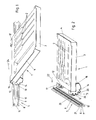
Fig. 1 eine Schrägsicht eines Ausführungsbeispiels einer Lagerschaleneinheit und einer Trageinheit, im verbundenen Zustand; -
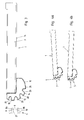
Fig. 2 undFig. 3 die Teile vonFig. 1 im voneinander getrennten Zustand, in einer Schrägsicht aus einer anderen Blickrichtung und in einer Seitenansicht; -
Fig. 4a eine Zwischenstellung beim Verbinden der Lagerschaleneinheit mit der Trageinheit, in Seitenansicht; -
Fig. 4b der verbundene Zustand in Seitenansicht; -
Fig. 5a und 5b Darstellungen entsprechendFig. 4a und 4b , aber für die Herstellung der Verbindung bzw. im verbundenen Zustand in einer gegenüber denFig. 4a und 4b anderen Winkelstellung der Lagerschaleneinheit; -
Fig.6a und Fig. 6b Darstellungen entsprechend denFig. 4a und 4b in einer weiteren Winkelstellung der Lagerschaleneinheit; -
Fig. 7 und 8 eine Vorderansicht und eine stirnseitige Ansicht der Lagereinheit; -
Fig. 9 einen Schnitt entlang der Linie A-A vonFig. 7 ; -
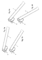
Fig. 10 eine Schrägsicht eines Verbindungsstücks zur Anbringung an einem Schalenkörper der Lagerschaleneinheit; -
Fig. 11 eine Draufsicht auf das Verbindungsstück; -
Fig. 12 einen Schnitt entlang der Linie B-B vonFig. 11 ; -
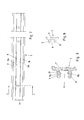
Fig. 13 ein modifiziertes Ausführungsbeispiel einer Lagerschaleneinheit und einer Trageinheit, im verbundenen Zustand; -
Fig. 14 eine Zwischenstellung beim Verbinden der Lagerschaleneinheit mit der Trageinheit gemäß dieser modifizierten Ausführungsform, in Seitenansicht; -
Fig. 15 ein vergrößertes Detail A vonFig. 14 ; -
Fig. 16 der verbundene Zustand in Seitenansicht; -
Fig. 17 ein vergrößertes Detail B vonFig. 16 ; -
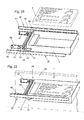
Fig. 18 der getrennte Zustand in Seitenansicht; -
Fig. 19 eine Schrägsicht eines Profilschienenabschnitts und einer Endkappe zur Ausbildung eines Verbindungsstücks gemäß der modifizierten Ausführungsform der Erfindung; -
Fig. 20 eine Schrägsicht eines Möbels mit einer Ausziehführung, welche eine erfindungsgemäße Lagerschaleneinheit aufweist, vom Möbel nur ein Abschnitt einer Seitenwand dargestellt; -
Fig. 21 eine auseinandergezogene Darstellung der Führungsschienen, des Schalenkörpers der Lagerschale und der Hartschaumeinlage der Lagerschale; -
Fig. 22 und 23 Darstellungen analogFig. 20 und Fig. 21 für ein weiteres Ausführungsbeispiel eines Möbels mit einer Ausziehführung.
-
Fig. 1 an oblique view of an embodiment of a bearing shell unit and a support unit, in the connected state; -
Fig. 2 andFig. 3 the parts ofFig. 1 in the separated state, in an oblique view from another direction and in a side view; -
Fig. 4a an intermediate position when connecting the bearing shell unit with the support unit, in side view; -
Fig. 4b the connected state in side view; -
Fig. 5a and 5b Representations accordinglyFig. 4a and 4b but for the preparation of the compound or in the connected state in a relation to theFig. 4a and 4b another angular position of the bearing shell unit; -
6a and 6b Representations according to theFig. 4a and 4b in a further angular position of the bearing shell unit; -
FIGS. 7 and 8 a front view and an end view of the storage unit; -
Fig. 9 a section along the line AA ofFig. 7 ; -
Fig. 10 an oblique view of a connector for attachment to a shell body of the bearing shell unit; -
Fig. 11 a plan view of the connector; -
Fig. 12 a section along the line BB ofFig. 11 ; -
Fig. 13 a modified embodiment of a bearing shell unit and a support unit, in the connected state; -
Fig. 14 an intermediate position when connecting the bearing shell unit with the support unit according to this modified embodiment, in side view; -
Fig. 15 an enlarged detail A ofFig. 14 ; -
Fig. 16 the connected state in side view; -
Fig. 17 an enlarged detail B ofFig. 16 ; -
Fig. 18 the disconnected state in side view; -
Fig. 19 an oblique view of a profile rail portion and an end cap for forming a connector according to the modified embodiment of the invention; -
Fig. 20 an oblique view of a piece of furniture with a pull-out guide, which has a bearing shell unit according to the invention, represented by the furniture only a portion of a side wall; -
Fig. 21 an exploded view of the guide rails, the shell body of the bearing shell and the Hartschaumeinlage the bearing shell; -
FIGS. 22 and 23 Representations analogFIGS. 20 and 21 for a further embodiment of a piece of furniture with a pull-out guide.
Ein erstes Ausführungsbeispiel für eine erfindungsgemäße Einrichtung ist in den
Die Einrichtung gemäß der Erfindung umfasst mindestens eine Lagerschaleneinheit 1, die zum Aufnehmen von zu lagernden Utensilien, beispielsweise Werkzeug ausgebildet ist. Vorzugsweise besitzt die Lagerschaleneinheit 1 hierzu Fächer 2, in welche die zu lagernden Utensilien einlegbar bzw. einsetzbar sind. Hierbei kann es sich, wie beispielhaft dargestellt, um an die aufzunehmenden Utensilien jeweils angepasste Fächer 2 handeln. Auch nicht speziell angepasste, beispielsweise rechteckige und/oder quadratische Fächer 2 können vorgesehen sein. Statt dessen könnte die Lagerschaleneinheit 1 auch nur eine Vertiefung, also ein einzelnes Fach, zur Aufnahme aller von der Lagerschaleneinheit 1 zu lagernden Utensilien besitzen.The device according to the invention comprises at least one
Im gezeigten Ausführungsbeispiel umfasst die Lagerschaleneinheit 1 einen eine Bodenwand und Seitenwände aufweisenden Schalenkörper 3, in den eine Hartschaumeinlage 4 eingesetzt ist, welche die Fächer 2 aufweist. Statt dessen könnten auch andere, die Fächer ausbildende Einlagen oder Einsätze, z. B. aus einem Kunststoffmaterial, vorgesehen sein oder das mindestens eine Fach 2 könnte direkt vom Schalenkörper 3 gebildet werden, ohne dass eine weitere Einlage oder ein weiterer Einsatz vorhanden wäre.In the exemplary embodiment shown, the bearing
Zum Tragen der Lagerschaleneinheit 1 dient eine Trageinheit 5, mit der die Lagerschaleneinheit 1 werkzeuglos verbindbar ist und von der die Lagerschaleneinheit 1 werkzeuglos abnehmbar ist. Eine erfindungsgemäße Einrichtung kann eine oder mehrere Trageinheiten umfassen. Eine jeweilige Trageinheit 5 wird direkt oder über mindesten ein weiteres dazwischen liegendes Teil an einem stationären Teil (beispielsweise einer Wand eines Gebäudes, eines Möbels oder einer Maschine oder an einem Traggestell) oder an einem verfahrbaren Wagen, einem verfahrbaren Möbel oder einer verfahrbaren Maschine befestigt. Die Befestigung erfolgt beispielsweise mittels Öffnungen 6 (vgl.
Die Trageinheit 5 ist im gezeigten Ausführungsbeispiel als Profilschiene, insbesondere in Form eines Aluminium-Strangpressprofils ausgebildet. Andere Ausbildungen sind möglich.The
Die Trageinheit 5 weist eine Aufnahmenut 8 auf, die sich im gezeigten Ausführungsbeispiel in Längsrichtung der Profilschiene durchgehend erstreckt. Die Aufnahmenut 8 läuft im Montagezustand der Trageinheit 5 horizontal.The
Die Aufnahmenut 8 wird von (bezogen auf den Montagezustand) oberen und unteren Begrenzungswänden 8a, 8b begrenzt. Diese werden hier von einem oberen und einem unteren Begrenzungssteg 9, 10 gebildet, die von einem vertikalen Basissteg 11 abstehen. Andere Ausbildungen der Aufnahmenut 8 sind denkbar und möglich.The receiving
Die Lagerschaleneinheit 1 besitzt auf einer Einsteckseite Nasen 12, 13, 14 zur Verbindung der Lagerschaleneinheit 1 mit der Trageinheit 5 in unterschiedlichen Winkelstellungen der Lagerschaleneinheit 1. In den unterschiedlichen Winkelstellungen der Lagerschaleneinheit 1 liegt ein Boden 15 der Lagerschaleneinheit 1 in unterschiedlich gegenüber der Horizontalen geneigten Ebenen, wobei eine dieser Ebenen vorzugsweise horizontal ist (also eine Neigung gegenüber der Horizontalen von 0° aufweist). Im gezeigten Ausführungsbeispiel betragen die möglichen Neigungswinkel 0°, 30° und 60°, wobei bei den Neigungswinkeln 30° und 60° die der Einsteckseite gegenüberliegende Seite der Lagerschaleneinheit tiefer liegt als die Einsteckseite. Andere und/oder zusätzliche Neigungswinkel könnten ebenfalls vorgesehen sein, insbesondere im Bereich von 0° bis 90°. Auch Neigungswinkel, bei denen die der Einsteckseite gegenüberliegenden Seite höher als die Einsteckseite liegt, könnten vorgesehen sein, beispielsweise im Bereich zwischen 0° und 45°.The bearing
Für jeden Neigungswinkel, in welchem die Lagerschaleneinheit mit der Trageinheit 5 verbindbar ist, ist mindestens eine Nase 12, 13, 14 der Lagerschaleneinheit 1 vorgesehen. Im gezeigten Ausführungsbeispiel sind für jeden Neigungswinkel zwei Nasen 12, 13, 14 vorgesehen.For each inclination angle in which the bearing shell unit is connectable to the
Vorteilhafterweise sind die Nasen 12, 13, 14 an ersten und zweiten Verbindungsstücken 16, 17 ausgebildet, die am Schalenkörper 3 befestigt sind, beispielsweise über eine Verschraubung (Schraublöcher sind in den
Die Verbindungsstücke 16, 17 können günstigerweise von Abschnitten von, insbesondere in Form von Hohlprofilen ausgebildeten, Profilschienen, vorzugsweise Aluminium-Strangpressprofilen, gebildet werden. Diese können beidseitig mit Abdeckungen versehen sein, um den inneren Hohlraum abzudecken.The connecting
Ein jeweiliges Verbindungsstück 16, 17 weist, entsprechend den gewünschten Winkelstellungen im mit der Trageinheit 5 verbundenen Zustand der Lagerschaleneinheit 1, in unterschiedliche winkelig zueinander stehende Richtungen sich erstreckende Nasen 12, 13, 14 auf.A respective connecting
Anstelle von zwei getrennten, voneinander beabstandeten Verbindungsstücken 16, 17, könnte auch ein einzelnes, die Nasen 12, 13, 14 aufweisendes Verbindungsstück vorgesehen sein. Denkbar und möglich wäre es auch, einen Schalenkörper 3 vorzusehen, an welchem direkt Nasen 12, 13, 14 angeformt sind (mindestens eine pro Winkelstellung).Instead of two separate, spaced-apart connecting
Im in einer der möglichen Winkelstellungen mit der Trageinheit 5 verbundenen Zustand der Lagerschaleneinheit 1 ist jeweils mindestens eine der Nasen 12, 13, 14 in die Aufnahmenut 8 eingesetzt, im gezeigten Ausführungsbeispiel sind in jeder Winkelstellung zwei Nasen 12, 13, 14 in die Aufnahmenut 8 eingesetzt.In connected in one of the possible angular positions with the
Eine jeweilige Nase 12, 13, 14 besitzt im Bereich ihres freien Endes einen Vorsprung 20, der im in die Aufnahmenut 8 eingesetzten Zustand der Nase 12, 13, 14 nach oben absteht und im mit der Trageinheit 5 verbundenen Zustand der Lagerschaleneinheit 1 in eine Vertiefung 21 in der oberen Begrenzungswand 8a der Aufnahmenut 8 ragt.A
Zum Verbinden der Lagerschaleneinheit 1 mit der Trageinheit 5 wird die der ausgewählten Winkelstellung der Lagerschaleneinheit 1 zugeordnete mindestens eine Nase 12, 13, 14 (im Ausführungsbeispiel zwei Nasen) in die Aufnahmenut 8 eingeführt, und zwar von der dem Nutgrund gegenüberliegenden offenen Seite der Aufnahmenut 8 her. Das Einstecken der jeweiligen mindestens einen Nase 12, 13, 14 erfolgt in eine Einsteckrichtung 22, welche also in Richtung der Tiefenerstreckung der Aufnahmenut 8 weist (und nicht etwa in Richtung der Längserstreckung der Aufnahmenut 8). Beim Abnehmen der Lagerschaleneinheit 1 von der Trageinheit 5 wird die mindestens eine in die Aufnahmenut 8 eingreifende Nase 12, 13, 14 in die der Einsteckrichtung 22 entgegengesetzte Herausziehrichtung herausgezogen.For connecting the bearing
Zum Einstecken der mindestens einen Nase 12, 13, 14 in die Aufnahmenut 8 wird die Lagerschaleneinheit 1 gegenüber der Stellung, welche sie im mit der Trageinheit 5 verbundenen Zustand einnimmt, um eine horizontale, parallel zur Längserstreckung der Aufnahmenut 8 liegende Achse verkippt angeordnet und in dieser Stellung geradlinig in die Einsteckrichtung 22 mit der mindestens einen Nase 12, 13, 14 in die Aufnahmenut 8 eingesteckt. Diese beim Einstecken eingenommene Stellung ist in den
Nach dem Einstecken derjeweiligen mindestens einen Nase wird die Lagerschaleneinheit mit ihrer der Einsteckseite gegenüberliegenden Seite abgesenkt, d. h. um eine im Bereich der Aufnahmenut 8 liegende horizontale, parallel zur Aufnahmenut 8 sich erstreckende Achse verkippt, bis die Lagerschaleneinheit 1 von der Trageinheit 5 gegen eine weitere Verkippung formschlüssig gehalten ist. Hierbei ragt der Vorsprung 20 in die Vertiefung 21, sodass die Lagerschaleneinheit 1 gegen ein geradliniges Herausziehen in die der Einsteckrichtung 22 entgegengesetzte Herausziehrichtung aus der Aufnahmenut 8 von der Trageinheit 5 formschlüssig gesichert ist.After insertion of the respective at least one nose, the bearing shell unit is lowered with its side opposite the insertion side, d. H. about an axis lying in the receiving
Der mit der Trageinheit 5 verbundene Zustand der Lagerschaleneinheit 1 ist für die verschiedenen Winkelstellungen in den
Zum Abnehmen der Lagerschaleneinheit 1 von der Trageinheit 5 wird der zuvor beschriebene Bewegungsablauf umgekehrt durchgeführt.To remove the bearing
Die mit der Trageinheit 5 verbundene und von der Trageinheit 5 getragene Lagerschaleneinheit 1 steht von der Trageinheit frei auskragend ab.The bearing
Im mit der Trageinheit 5 verbundenen Zustand der Lagerschaleneinheit 1 stützt sich die mindestens eine in die Aufnahmenut 8 eingesetzte Nase 12, 13, 14 mit einem Anlagebereich an der oberen Begrenzungswand 8a der Aufnahmenut 8 ab. Dieser Anlagebereich kann vom Vorsprung 20 oder einem dem Vorsprung 10 benachbarten Bereich der Nase 12, 13, 14 gebildet werden. Weiters liegt die Nase mit einem weiter vom Nutgrund entfernt gelegenen Auflagebereich auf der unteren Begrenzungswand 8b auf. Statt dessen könnte sich auch ein außerhalb der Aufnahmenut 8 liegender Abstützbereich der Lagerschaleneinheit 1, der unterhalb der mindestens einen in die Aufnahmenut 8 ragenden Nase 12, 13, 14 liegt, stirnseitig an der Trageinheit 5 abstützen, beispielsweise am freien Ende des unteren Begrenzungsstegs 10.In connected to the
Wenn die schienenförmig ausgebildete Trageinheit 5 sich beidseitig über die Lagerschaleneinheit 1 hinaus erstreckt, wie dies in
Im gezeigten Ausführungsbeispiel sind nur eine einzelne Lagerschaleneinheit 1 und eine einzelne Trageinheit 5 dargestellt. In vielen Anwendungsfällen wird eine erfindungsgemäße Einrichtung mehrere, in der Montagelage vorzugsweise übereinander angeordnete Trageinheiten 5 und mehrere Lagerschaleneinheiten 1 umfassen. Günstigerweise sind hierbei die Lagerschaleneinheiten 1 zumindest im jeweiligen Verbindungsbereich gleich ausgebildet und sind die Trageinheiten 5 zumindest im jeweiligen Verbindungsbereich gleich ausgebildet. Es kann also frei gewählt werden, welche der Lagerschaleneinheit 1 mit welcher der Trageinheit 5 verbunden wird.In the embodiment shown, only a single
Die Verbindungsstücke 16, 17 weisen eine Nut 25 zum Einsetzen einer Gummileiste 26 auf, sodass die Lagerschaleneinheit 1 im Bereich der Verbindungsstücke 16, 17 schonend auf einer Unterlage abstellbar ist. Im Bereich der gegenüberliegenden Seite der Lagerschaleneinheit 1 können an der Unterseite ebenfalls Gummielemente zum Abstellen auf einer Unterlage vorgesehen sein.The connecting
Ein modifiziertes Ausführungsbeispiel der Erfindung ist in den
Bei diesem modifizierten Ausführungsbeispiel sind die Nasen 12, 13, 14 zusätzlich zu den jeweils im in die Aufnahmenut 8 eingesetzten Zustand nach oben abstehenden Vorsprüngen 20 mit nach unten abstehenden Schnappvorsprüngen 27 versehen. Die Schnappvorsprünge 27 werden im gezeigten Ausführungsbeispiel von Endkappen 28 gebildet, die den Profilschienenabschnitt 29 des jeweiligen Verbindungsstücks 16, 17 stirnseitig verschließen. In
Die Endkappen 28 bestehen vorzugsweise aus Kunststoff. Um ein federelastisches Eindrücken der Schnappvorsprünge 27 zu ermöglichen, sind die Endkappen 28 in den Schnappvorsprüngen 27 benachbarten Bereichen vorzugsweise mit Öffnungen 30 versehen.The end caps 28 are preferably made of plastic. In order to allow a resilient impressions of the
Zum Verbinden der Lagerschaleneinheit 1 mit der Trageinheit 5 wird, wie im zuvor beschriebenen Ausführungsbeispiel, zunächst die Lagerschaleneinheit 1 gegenüber der Endstellung verschwenkt, wobei die freie Seite der Lagerschaleneinheit 1 weiter oben als in der Endstellung liegt, und die entsprechende Nase 12, 13, 14 wird in dieser Stellung in die Aufnahmenut 8 eingeführt, vgl.
Schnappvorsprünge 27 könnten auch in anderer Weise ausgebildet werden, beispielsweise durch ein Schnappelement, das gegen die Kraft einer Feder verschiebbar ist. Schnappvorsprünge könnten auch direkt an den Profilschienenabschnitten 29 ausgebildet sein.Snap-on
Die
Abgesehen von diesen Laufrollen 33 kann die Lagerschaleneinheit gleich wie in den zuvor beschriebenen Ausführungsbeispielen ausgebildet sein. Beispielsweise können die Laufrollen 33 an den Verbindungsstücken 16, 17 drehbar gelagert sein, z.B. indem Achsen der Laufrollen 33 in Aufnahmeöffnungen 34 (vgl.
Die Laufrollen 33 sind in erste und zweite Führungsschienen 35, 36 einsetzbar. Im in die Führungsschienen 35, 36 eingesetzten Zustand ist die Lagerschaleneinheit 1, von der zumindest ein Abschnitt zwischen den Führungsschienen 35, 36 liegt, in Längsrichtung der Führungsschienen 35, 36 verschiebbar.The
An der jeweiligen Führungsschiene 35, 36 ist eine Laufrolle 37 im Bereich des vorderen Endes der Führungsschiene 35, 36 drehbar gelagert. Das vordere Ende der Führungsschiene 35, 36 ist dasjenige, von dem her die Lagerschaleneinheit 1 bei ihrer Verbindung mit den Führungsschienen 35, 36 zugeführt wird. Die mit den Führungsschienen 35, 36 verbundene Lagerschaleneinheit 1 liegt mit einem jeweiligen Laufsteg 38 auf der jeweiligen Laufrolle 37 auf.At the
Abgesehen von Bereichen ihrer vorderen Endabschnitte sind die Führungsschienen 35, 36 im Querschnitt C-förmig ausgebildet mit oberen und unteren Laufstegen 39, 40, die durch einen Basissteg 41 miteinander verbunden sind. Zwischen den Laufstegen 39, 40 kann die jeweilige Laufrolle 33 der Lageschaleneinheit 1 abrollen. Der obere Laufsteg 39 endet im Abstand vom vorderen Ende der jeweiligen Führungsschiene 35, 36 oder weist in der Nähe dieses vorderen Endes eine Ausnehmung auf. Durch diese freigestellten Bereiche können die Laufrollen 33 bei der Verbindung der Lagerschaleneinheit 1 mit den Führungsschienen 35, 36 hinter den Laufrollen 37 in den Zwischenraum zwischen den Laufstegen 39, 40 der Führungsschienen 35, 36 eingeführt werden.Apart from areas of their front end portions, the guide rails 35, 36 in cross-section C-shaped with upper and
Um ein ungewolltes Herausfahren der Laufrollen 33 aus den freigestellten Abschnitten der oberen Laufstege 39 im ausgezogenen Zustand der Lagerschaleneinheit 1 zu verhindern, können unterschiedliche Maßnahmen vorgesehen sein. Beispielsweise könnte ein Anschlag vorgesehen sein, der das Ausziehen der Lagerschaleneinheit 1 an einer Stelle begrenzt, bevor die Laufrollen 33 zu den freigestellten Bereichen der oberen Laufstege 39 gelangen, und der durch Anheben des vorderen Endes der Lagerschaleneinheit 1 überwunden werden kann.In order to prevent unwanted retraction of the
Auf diese Weise wird eine Ausziehführung gebildet, sodass die Lagerschaleneinheit 1 als Schublade genutzt werden kann. Ein Möbel kann mit einem oder mehreren Paaren von Führungsschienen 35, 36 ausgestattet sein, um ein oder mehrere Lagerschaleneinheiten 1 gleichzeitig als Schubladen einsetzen zu können. In
Eine weitere mögliche Ausbildungsform zur Bereitstellung einer Ausziehführung ist in den
Die Führungseinheit 42 besitzt weiters eine Aufnahmenut 45, die die gleiche Querschnittsform (Querschnittskontur) wie die Aufnahmenut 8 der mindestens einen Trageinheit 5 aufweist. Im Ausführungsbeispiel sind die Laufrollen 43, 44 an Tragschienen 46, 47 drehbar gelagert, die durch eine Profilschiene 48 miteinander verbunden sind, welche die Aufnahmenut 45 aufweist. Die Tragschienen 46, 47 und die Profilschiene 48 stehen hierbei rechtwinkelig zueinander. Die Profilschiene 48 weist die gleiche Profilform wie die Trageinheit 5 auf.The
Die Lagerschaleneinheit 1 ist somit über ihre Nasen 12, 13, 14 mit der Profilschiene 48 verbindbar, vorzugsweise über die mindestens eine Nase 12, mit der eine horizontale Ausrichtung der mit der Profilschiene 48 verbundenen Lagerschaleneinheit 1 erreicht wird.The bearing
Damit kann die Lagerschaleneinheit 1 als Schublade eingesetzt werden. Ein Möbel 50 kann ein oder mehrere Paare von Führungsschienen 35, 36 aufweisen, von denen jeweils eine Führungseinheit 42 verschiebbar geführt ist. Mit einer jeweiligen Führungseinheit 42 kann eine Lagerschaleneinheit 1 verbunden werden, sodass eine entsprechende Anzahl von Schubladen ausgebildet werden kann.Thus, the bearing
Wenn die Lagerschaleneinheit 1 von der Führungseinheit 42 abgenommen wird, kann diese wie im Zusammenhang mit den
In den Ausführungsbeispielen entsprechend
In der beschriebenen Weise kann beispielsweise ein Möbel 50 in Form eines Werkzeugschrankes ausgebildet werden.
Claims (13)
- Device for storing implements, especially tools, which comprises at least one storage-tray unit (1) to receive implements to be stored and at least one supporting unit (5) to which the storage-tray unit (1) can be connected to allow said storage-tray unit (1) to be supported and from which the storage-tray unit (1) can be removed, the storage-tray unit (1) having noses (12, 13, 14) which can be inserted in a receiving groove (8) in the supporting unit (5) to connect the storage-tray unit (1) to the supporting unit (5), and the storage-tray unit (1),
when connected to the supporting unit (5), projecting from the supporting unit (5), and at least one storage-tray unit (1) being able to be connected to the supporting unit (5) in at least two different angular positions relative to a horizontal axis, and different noses (12, 13, 14) belonging to the storage-tray unit (1) being insertable in the receiving groove (8) in the supporting unit (5) to connect the storage-tray unit (1) to the supporting unit (5) in different angular positions, characterised in that any given nose (12, 13, 14) has a protrusion (20) which projects upwards in the state where insertion in the receiving groove (8) has taken place and which engages in a depression (21) in the upper boundary wall (8a) of the receiving groove (8) in the state where the storage-tray unit (1) is connected to the supporting unit (5), the storage-tray unit (1) being secured by positive interengagement against being pulled out of the supporting unit (5) in a straight line. - Device according to claim 1, characterised in that, on its side which is at the bottom in the state where insertion in the receiving groove (8) has taken place, any given nose (12, 13, 14) has a bevel and/or rounding (23) which narrows its cross-section in the direction of its end.
- Device according to claim 1 or 2, characterised in that the supporting unit (5) or any given supporting unit (5) is formed by a rail in profile form having a continuous receiving groove (8) for the insertion of the at least one nose (12, 13, 14) belonging to the storage-tray unit (1), or comprises such a rail.
- Device according to claim 3, characterised in that, in the state where it is connected to the supporting unit (5), the storage-tray unit (1) is displaceable horizontally, with the at least one nose (12, 13, 14) belonging to the storage-tray unit (1), when inserted in the receiving groove (8), being displaceable in the longitudinal direction of the receiving groove (8).
- Device according to one of claims 1 to 4, characterised in that the device comprises a plurality of supporting units (5) arranged or arrangeable at different heights, and a plurality of storage-tray units (1) able to be connected to the supporting units (5) as and when desired.
- Device according to one of claims 1 to 5, characterised in that any given storage-tray unit (1) has a tray-forming body (3), on one side of which are mounted first and second connecting pieces (16, 17) spaced apart from one another which each have noses (12, 13) for insertion in the receiving groove (8).
- Device according to claim 6, characterised in that the first and second connecting pieces each have a portion (29) made up of a rail in profile form, or are formed thereby.
- Device according to one of claims 1 to 7, characterised in that there is inserted in the tray-forming body (3) an insert of rigid foam (4) which has compartments (2) to receive implements to be stored.
- Device according to one of claims 1 to 8, characterised in that at least some of the noses (12, 13, 14) have at least one snap-in protrusion (27) which projects downwards in the state where insertion in the receiving groove (8) has taken place and which can be snapped into a depression for snap-in insertion (32) in the lower boundary wall (8b) of the receiving groove (8) when the nose (12, 13, 14) is inserted in the receiving groove (8).
- Device according to one of claims 1 to 9, characterised in that the storage-tray unit (1) has at least two travel rollers (33) which are mounted on opposite sides of the storage-tray unit (1) to be rotatable, the storage-tray unit (1), to form a pull-out slide assembly with the travel rollers (33), being insertable in first and second guide rails (35, 36) in which the storage-tray unit (1) is mounted to be displaceable in the longitudinal direction of the guide rails (35, 36).
- Device according to one of claims 1 to 9, characterised in that the device comprises a guided unit (42) and the guided unit (42) has a receiving groove (45) in which at least one of the noses (12, 13, 14) of the storage-tray unit (1) can be inserted to connect the storage-tray unit (1) to the guided unit (42), the storage-tray unit (1), when connected to the guided unit (42), projecting from said guided unit (42) and, to form a pull-out slide assembly, the guided unit (42) being mounted to be displaceable relative to, in the longitudinal direction of, first and second guide rails (35, 36) which are arranged on the two sides of the guided unit (42).
- Pull-out slide assembly which comprises a device according to claim 10 or 11.
- Piece of furniture having at least one pull-out slide assembly which comprises a device according to claim 10 or 11.
Priority Applications (1)
| Application Number | Priority Date | Filing Date | Title |
|---|---|---|---|
| PL12783487T PL2765886T3 (en) | 2011-10-13 | 2012-10-04 | Device for storing utensils, especially tools |
Applications Claiming Priority (2)
| Application Number | Priority Date | Filing Date | Title |
|---|---|---|---|
| ATA1487/2011A AT512009B1 (en) | 2011-10-13 | 2011-10-13 | DEVICE FOR STORING UTENSILS, ESPECIALLY TOOLS |
| PCT/AT2012/000249 WO2013052975A1 (en) | 2011-10-13 | 2012-10-04 | Device for storing utensils, especially tools |
Publications (2)
| Publication Number | Publication Date |
|---|---|
| EP2765886A1 EP2765886A1 (en) | 2014-08-20 |
| EP2765886B1 true EP2765886B1 (en) | 2016-01-13 |
Family
ID=47146122
Family Applications (1)
| Application Number | Title | Priority Date | Filing Date |
|---|---|---|---|
| EP12783487.7A Active EP2765886B1 (en) | 2011-10-13 | 2012-10-04 | Device for storing utensils, especially tools |
Country Status (11)
| Country | Link |
|---|---|
| US (1) | US9247810B2 (en) |
| EP (1) | EP2765886B1 (en) |
| JP (1) | JP6259398B2 (en) |
| CN (1) | CN103997934B (en) |
| AT (1) | AT512009B1 (en) |
| AU (1) | AU2012323804B2 (en) |
| CA (1) | CA2851295A1 (en) |
| DE (1) | DE202012012595U1 (en) |
| ES (1) | ES2566070T3 (en) |
| PL (1) | PL2765886T3 (en) |
| WO (1) | WO2013052975A1 (en) |
Families Citing this family (20)
| Publication number | Priority date | Publication date | Assignee | Title |
|---|---|---|---|---|
| US9142150B2 (en) * | 2012-04-10 | 2015-09-22 | Target Brands, Inc. | Sign holder assembly and associated method |
| DE102014005211A1 (en) | 2014-04-09 | 2015-10-15 | Oliver Horstmeyer | Flexible functional device element |
| EP3078548B1 (en) | 2015-04-09 | 2018-08-29 | Modul-System HH AB | A storage system |
| DE102015206606A1 (en) * | 2015-04-14 | 2016-10-20 | Adolf Würth GmbH & Co. KG | Assortment box and arrangement with at least one assortment box and a retaining strip |
| CN105415334B (en) * | 2015-11-27 | 2017-05-31 | 河南新科起重机股份有限公司 | A kind of crane hoisting motor finished product tooth axle laying rack |
| WO2017134521A1 (en) * | 2016-02-01 | 2017-08-10 | Ranger Design | High density foldaway shelving |
| USD790926S1 (en) | 2016-04-28 | 2017-07-04 | Base4 Ventures, Llc | Grill trivet |
| CN106545557B (en) * | 2016-11-28 | 2023-11-03 | 江苏隆基铝业有限公司 | Aluminum alloy section bar connecting piece |
| CN106628501B (en) * | 2016-11-29 | 2018-07-10 | 无锡特恒科技有限公司 | Mistake proofing pallet apparatus |
| US11317902B2 (en) | 2017-06-15 | 2022-05-03 | DePuy Synthes Products, Inc. | SST retractor with radiolucent feature |
| CN107319766B (en) * | 2017-06-30 | 2019-01-22 | 中山市翔实机械设备有限公司 | It is a kind of can 360 degree rotation intelligent cabinet |
| US10500713B2 (en) * | 2017-09-14 | 2019-12-10 | Black & Decker Inc. | Wall hanging system |
| US20190202230A1 (en) * | 2018-01-02 | 2019-07-04 | Studio Designs Inc. | Art supplies organization assembly |
| DE102018104809A1 (en) * | 2018-03-02 | 2019-09-05 | Rickard Nilsson | Shelf and shelf arrangement |
| DE102018110955A1 (en) * | 2018-05-08 | 2019-11-14 | Bystronic Laser Ag | Tool storage device for a machine tool and machine tool |
| EP3666474A1 (en) * | 2018-12-12 | 2020-06-17 | Hilti Aktiengesellschaft | Holding device for an electronic device and module |
| SE543492C2 (en) * | 2019-02-06 | 2021-03-09 | Ikea Supply Ag | A drawer sliding system |
| GB2584477B (en) * | 2019-06-06 | 2021-09-22 | Keymed Medical & Industrial Equipment Ltd | Mounting system for a medical workstation |
| JP2021144187A (en) * | 2020-03-13 | 2021-09-24 | ヤマハ株式会社 | Musical instrument and keyboard instrument |
| LU500933B1 (en) | 2021-11-30 | 2023-06-02 | Better Basics Laborbedarf Gmbh | Clamp slide rail mounting device |
Family Cites Families (55)
| Publication number | Priority date | Publication date | Assignee | Title |
|---|---|---|---|---|
| NL107523C (en) * | 1959-04-28 | |||
| US3093094A (en) * | 1962-01-17 | 1963-06-11 | Muammer A Oztekin | Adjustable shelf support |
| NL6704277A (en) * | 1966-03-28 | 1967-09-29 | ||
| US3463433A (en) * | 1967-08-08 | 1969-08-26 | Grant Pulley & Hardware Corp | Adjustable bracket |
| US3550891A (en) * | 1968-12-04 | 1970-12-29 | Charles F Scott | Adjustable shelf bracket |
| US3631821A (en) * | 1969-09-11 | 1972-01-04 | Basil Zachariou | Shelving assemblies |
| US3700114A (en) * | 1971-01-18 | 1972-10-24 | Clark Equipment Co | Adjustable shelf support bracket |
| US3795379A (en) * | 1972-09-13 | 1974-03-05 | Ebsco Ind Inc | Adjustable shelf support |
| US4008873A (en) * | 1976-01-29 | 1977-02-22 | Emhart Industries, Inc. | Angularly adjustable shelf bracket |
| CA1043298A (en) * | 1976-11-16 | 1978-11-28 | J. A. Wilson Display Limited | Display structure |
| US4228906A (en) * | 1978-09-14 | 1980-10-21 | Kardex Systems, Inc. | Adjustable rail mounting assembly |
| US4307671A (en) * | 1980-05-05 | 1981-12-29 | The Kent Corporation | Merchandise shelving display |
| US4609173A (en) * | 1984-10-01 | 1986-09-02 | Martin-Paul, Inc. | Magnetically attachable towel hanger |
| DE8518079U1 (en) | 1985-06-21 | 1985-08-29 | Bosch-Siemens Hausgeräte GmbH, 8000 München | Hanging box |
| SE457631B (en) * | 1987-06-02 | 1989-01-16 | Btj Produkter Ab | STORAGE SYSTEM SPECIFICALLY BEFORE MAGAZINES AND DIRECTLY |
| JPH0725064Y2 (en) * | 1987-07-24 | 1995-06-07 | 株式会社岡村製作所 | Shelf support device |
| US4869378A (en) * | 1988-08-29 | 1989-09-26 | Hospital Systems, Inc. | Mounting rail for hospital appliances and bracket |
| JPH0382178U (en) * | 1989-12-15 | 1991-08-21 | ||
| US5169221A (en) * | 1990-09-04 | 1992-12-08 | General Devices Co., Inc. | Pivotable drawer slide mount with pivot controlling guide slot |
| US5117986A (en) * | 1991-04-19 | 1992-06-02 | Lin Hsin Hsiung | Shelf with height and angle adjustment |
| CN2098844U (en) | 1991-09-11 | 1992-03-18 | 张弘毅 | Frame being able to adjust hanging agle |
| US5275281A (en) | 1992-07-17 | 1994-01-04 | Ebeling Keith R | Micrometer organizing and protecting device |
| EP0650338A4 (en) * | 1992-07-22 | 1995-08-23 | Rene Wilhelm Crooymans | Shelving support system. |
| US5244272A (en) * | 1992-11-02 | 1993-09-14 | Thompson Donn K | Space-saving undercabinet spice jar drawer |
| US5259519A (en) * | 1993-01-11 | 1993-11-09 | Lieberman William B | Advertiser and hygienic disposable toothbrush holder |
| DE9301716U1 (en) | 1993-02-08 | 1993-05-19 | Huang, Che-Hsiung, Taipeh/T'ai-Pei, Tw | |
| US5452875A (en) * | 1994-04-21 | 1995-09-26 | Discovery Plastics, Inc. | Plastic support assembly |
| GB2297896A (en) * | 1995-02-02 | 1996-08-21 | Artform Int Ltd | Tiltable shelf |
| DE19646531A1 (en) | 1996-10-29 | 1998-06-10 | Wilfried Poellet | Utensil-holder panel for domestic workshop |
| US5960965A (en) * | 1996-11-12 | 1999-10-05 | Saunders; Todd R. | Product display system |
| KR100245626B1 (en) * | 1997-06-30 | 2000-02-15 | 강병호 | Keyboard tilting device for portable computers |
| US5941026A (en) * | 1998-01-20 | 1999-08-24 | Storewall Llc | Slatwall display system |
| TW404638U (en) * | 1999-03-18 | 2000-09-01 | Chiou Huei Min | Plane monitor used foot seat |
| CN2371868Y (en) | 1999-03-31 | 2000-04-05 | 三豪有限公司 | Slideway folding mechanism |
| CN2413791Y (en) | 1999-04-08 | 2001-01-10 | 北京华信文化发展有限责任公司 | Scientific experiment box |
| AU5895599A (en) * | 1999-08-12 | 2001-03-13 | Furn Li Lee | A storage system |
| US6487979B2 (en) * | 2000-03-15 | 2002-12-03 | Utilimaster | Stowable shelf assembly |
| DE10153621A1 (en) | 2001-10-31 | 2003-05-22 | Bsh Bosch Siemens Hausgeraete | Refrigerator with adjustable shelves |
| US6648390B1 (en) | 2002-05-21 | 2003-11-18 | Global Industries Holdings Ltd. | Single-stack tool rack |
| DE20314773U1 (en) * | 2003-09-22 | 2003-12-04 | Elabo Gmbh | Support rail for wall mounted storage containers has different pattern upper and lower edges to match different types of container |
| US7140703B1 (en) * | 2004-09-14 | 2006-11-28 | Holdgate Iii Edward | Pull-out and tilt guide assembly for a drawer |
| TWI263571B (en) * | 2004-10-26 | 2006-10-11 | Global Ind Holdings Ltd | Hand tool storage stand |
| NO323380B1 (en) | 2004-11-29 | 2007-04-16 | Ebeco As | Device on wheeled rack |
| DE202004020115U1 (en) * | 2004-12-29 | 2006-05-11 | Liebherr-Hausgeräte Ochsenhausen GmbH | cooling unit |
| GB2423790A (en) | 2005-03-03 | 2006-09-06 | Tung Chieh Ind Co Ltd | A locking control unit for tool box drawers |
| US7527156B2 (en) * | 2005-07-12 | 2009-05-05 | Whirlpool Corporation | Tool caddy |
| US20070017886A1 (en) * | 2005-07-20 | 2007-01-25 | Jui-Chien Kao | Suspension display rack |
| US20070278168A1 (en) * | 2006-05-11 | 2007-12-06 | Li Wayne K | Decorative wall hanging assembly |
| US8550265B2 (en) | 2007-01-31 | 2013-10-08 | Kirk J. Botkin | Support systems and components for same |
| JP3132743U (en) * | 2007-03-26 | 2007-06-21 | 法明 西本 | Shelf device with tiltable shelf board |
| US20090161309A1 (en) * | 2007-12-21 | 2009-06-25 | Ching Lun Yang | Removable hard drive casing |
| WO2010054683A1 (en) | 2008-11-11 | 2010-05-20 | BSH Bosch und Siemens Hausgeräte GmbH | Refrigeration device having adjustable-height refrigerated goods placement |
| US8136775B2 (en) * | 2009-06-30 | 2012-03-20 | Vance Chiang | Rack assembly |
| JP3166150U (en) * | 2010-10-03 | 2011-02-24 | 信一 小屋野 | Organized tray |
| US8882065B2 (en) * | 2011-04-26 | 2014-11-11 | Kimball International, Inc. | Two piece track assembly |
-
2011
- 2011-10-13 AT ATA1487/2011A patent/AT512009B1/en active
-
2012
- 2012-10-04 US US14/350,430 patent/US9247810B2/en active Active
- 2012-10-04 EP EP12783487.7A patent/EP2765886B1/en active Active
- 2012-10-04 DE DE202012012595U patent/DE202012012595U1/en not_active Expired - Lifetime
- 2012-10-04 AU AU2012323804A patent/AU2012323804B2/en active Active
- 2012-10-04 JP JP2014534868A patent/JP6259398B2/en active Active
- 2012-10-04 WO PCT/AT2012/000249 patent/WO2013052975A1/en active Application Filing
- 2012-10-04 ES ES12783487.7T patent/ES2566070T3/en active Active
- 2012-10-04 CN CN201280050138.1A patent/CN103997934B/en active Active
- 2012-10-04 CA CA2851295A patent/CA2851295A1/en not_active Abandoned
- 2012-10-04 PL PL12783487T patent/PL2765886T3/en unknown
Also Published As
| Publication number | Publication date |
|---|---|
| WO2013052975A1 (en) | 2013-04-18 |
| CA2851295A1 (en) | 2013-04-18 |
| AT512009A1 (en) | 2013-04-15 |
| AT512009B1 (en) | 2014-04-15 |
| PL2765886T3 (en) | 2016-07-29 |
| CN103997934B (en) | 2017-04-05 |
| AU2012323804A1 (en) | 2014-04-24 |
| US20140265789A1 (en) | 2014-09-18 |
| DE202012012595U1 (en) | 2013-07-05 |
| EP2765886A1 (en) | 2014-08-20 |
| ES2566070T3 (en) | 2016-04-08 |
| JP2014531947A (en) | 2014-12-04 |
| CN103997934A (en) | 2014-08-20 |
| AU2012323804B2 (en) | 2016-10-27 |
| US9247810B2 (en) | 2016-02-02 |
| JP6259398B2 (en) | 2018-01-10 |
Similar Documents
| Publication | Publication Date | Title |
|---|---|---|
| EP2765886B1 (en) | Device for storing utensils, especially tools | |
| WO2008095766A2 (en) | Domestic appliance comprising a support system | |
| EP1929224B1 (en) | Refrigerator with a divided shelf | |
| EP2907470B1 (en) | Device trolley | |
| AT512008B1 (en) | DEVICE FOR STORING UTENSILS, ESPECIALLY TOOLS | |
| EP2844108B1 (en) | Holding device for a supporting element of a cabinet, such as a refrigerator, a freezer or a cabinet for storing wine | |
| DE102007059204A1 (en) | Switch cabinet or rack, has side walls comprising end sections at lower and/or upper boundary region, where supports of base and/or cover are inserted into end sections and secured by securing elements | |
| WO2008122515A2 (en) | Refrigerated product tray and refrigeration device equipped therewith | |
| DE8018254U1 (en) | ASSORTMENT BOX SHELF | |
| DE2431462C2 (en) | Dividing organ for drawers | |
| EP0063805A2 (en) | Rack for storing and displaying articles | |
| EP1984686A2 (en) | Refrigeration device and shelves therefor | |
| EP2353444B1 (en) | Cupboard drawer | |
| EP2454542A2 (en) | Support for refrigerated products in a refrigeration appliance | |
| DE102009046027A1 (en) | Refrigeration equipment, particularly household refrigerator, for use with refrigerated product carrier, is provided with shelves, where panels are pivoted around horizontal axis | |
| DE3537335C2 (en) | ||
| DE202006014590U1 (en) | Divider insert especially for a kitchen drawer has two parallel sides with inner vertical grooves to fit dividing walls | |
| DE3129573C2 (en) | Construction kit for furniture, in particular add-on furniture | |
| WO1992006627A1 (en) | Bookshelf for a display frame system | |
| EP2327332A1 (en) | Shelving system | |
| CH681287A5 (en) | Support for suspended file holders | |
| DE19811755C2 (en) | Switch cabinet or switch frame with base frame | |
| DE1907776A1 (en) | Display boards, in particular for planning purposes | |
| DE1654628A1 (en) | Furniture kit | |
| DE3645007C2 (en) |
Legal Events
| Date | Code | Title | Description |
|---|---|---|---|
| PUAI | Public reference made under article 153(3) epc to a published international application that has entered the european phase |
Free format text: ORIGINAL CODE: 0009012 |
|
| 17P | Request for examination filed |
Effective date: 20140307 |
|
| AK | Designated contracting states |
Kind code of ref document: A1 Designated state(s): AL AT BE BG CH CY CZ DE DK EE ES FI FR GB GR HR HU IE IS IT LI LT LU LV MC MK MT NL NO PL PT RO RS SE SI SK SM TR |
|
| RAP1 | Party data changed (applicant data changed or rights of an application transferred) |
Owner name: METZLER GMBH & CO KG |
|
| DAX | Request for extension of the european patent (deleted) | ||
| GRAP | Despatch of communication of intention to grant a patent |
Free format text: ORIGINAL CODE: EPIDOSNIGR1 |
|
| INTG | Intention to grant announced |
Effective date: 20150812 |
|
| GRAS | Grant fee paid |
Free format text: ORIGINAL CODE: EPIDOSNIGR3 |
|
| GRAA | (expected) grant |
Free format text: ORIGINAL CODE: 0009210 |
|
| AK | Designated contracting states |
Kind code of ref document: B1 Designated state(s): AL AT BE BG CH CY CZ DE DK EE ES FI FR GB GR HR HU IE IS IT LI LT LU LV MC MK MT NL NO PL PT RO RS SE SI SK SM TR |
|
| REG | Reference to a national code |
Ref country code: GB Ref legal event code: FG4D Free format text: NOT ENGLISH |
|
| REG | Reference to a national code |
Ref country code: CH Ref legal event code: EP |
|
| REG | Reference to a national code |
Ref country code: IE Ref legal event code: FG4D Free format text: LANGUAGE OF EP DOCUMENT: GERMAN |
|
| REG | Reference to a national code |
Ref country code: AT Ref legal event code: REF Ref document number: 769907 Country of ref document: AT Kind code of ref document: T Effective date: 20160215 |
|
| REG | Reference to a national code |
Ref country code: DE Ref legal event code: R096 Ref document number: 502012005739 Country of ref document: DE |
|
| REG | Reference to a national code |
Ref country code: CH Ref legal event code: NV Representative=s name: SCHNEIDER FELDMANN AG PATENT- UND MARKENANWAEL, CH |
|
| REG | Reference to a national code |
Ref country code: SE Ref legal event code: TRGR |
|
| REG | Reference to a national code |
Ref country code: ES Ref legal event code: FG2A Ref document number: 2566070 Country of ref document: ES Kind code of ref document: T3 Effective date: 20160408 |
|
| REG | Reference to a national code |
Ref country code: NL Ref legal event code: FP |
|
| REG | Reference to a national code |
Ref country code: LT Ref legal event code: MG4D |
|
| REG | Reference to a national code |
Ref country code: NO Ref legal event code: T2 Effective date: 20160113 |
|
| PG25 | Lapsed in a contracting state [announced via postgrant information from national office to epo] |
Ref country code: GR Free format text: LAPSE BECAUSE OF FAILURE TO SUBMIT A TRANSLATION OF THE DESCRIPTION OR TO PAY THE FEE WITHIN THE PRESCRIBED TIME-LIMIT Effective date: 20160414 Ref country code: HR Free format text: LAPSE BECAUSE OF FAILURE TO SUBMIT A TRANSLATION OF THE DESCRIPTION OR TO PAY THE FEE WITHIN THE PRESCRIBED TIME-LIMIT Effective date: 20160113 |
|
| PG25 | Lapsed in a contracting state [announced via postgrant information from national office to epo] |
Ref country code: RS Free format text: LAPSE BECAUSE OF FAILURE TO SUBMIT A TRANSLATION OF THE DESCRIPTION OR TO PAY THE FEE WITHIN THE PRESCRIBED TIME-LIMIT Effective date: 20160113 Ref country code: LT Free format text: LAPSE BECAUSE OF FAILURE TO SUBMIT A TRANSLATION OF THE DESCRIPTION OR TO PAY THE FEE WITHIN THE PRESCRIBED TIME-LIMIT Effective date: 20160113 Ref country code: PT Free format text: LAPSE BECAUSE OF FAILURE TO SUBMIT A TRANSLATION OF THE DESCRIPTION OR TO PAY THE FEE WITHIN THE PRESCRIBED TIME-LIMIT Effective date: 20160513 Ref country code: IS Free format text: LAPSE BECAUSE OF FAILURE TO SUBMIT A TRANSLATION OF THE DESCRIPTION OR TO PAY THE FEE WITHIN THE PRESCRIBED TIME-LIMIT Effective date: 20160513 Ref country code: LV Free format text: LAPSE BECAUSE OF FAILURE TO SUBMIT A TRANSLATION OF THE DESCRIPTION OR TO PAY THE FEE WITHIN THE PRESCRIBED TIME-LIMIT Effective date: 20160113 |
|
| REG | Reference to a national code |
Ref country code: DE Ref legal event code: R097 Ref document number: 502012005739 Country of ref document: DE |
|
| PG25 | Lapsed in a contracting state [announced via postgrant information from national office to epo] |
Ref country code: EE Free format text: LAPSE BECAUSE OF FAILURE TO SUBMIT A TRANSLATION OF THE DESCRIPTION OR TO PAY THE FEE WITHIN THE PRESCRIBED TIME-LIMIT Effective date: 20160113 Ref country code: DK Free format text: LAPSE BECAUSE OF FAILURE TO SUBMIT A TRANSLATION OF THE DESCRIPTION OR TO PAY THE FEE WITHIN THE PRESCRIBED TIME-LIMIT Effective date: 20160113 |
|
| REG | Reference to a national code |
Ref country code: FR Ref legal event code: PLFP Year of fee payment: 5 |
|
| PLBE | No opposition filed within time limit |
Free format text: ORIGINAL CODE: 0009261 |
|
| STAA | Information on the status of an ep patent application or granted ep patent |
Free format text: STATUS: NO OPPOSITION FILED WITHIN TIME LIMIT |
|
| PG25 | Lapsed in a contracting state [announced via postgrant information from national office to epo] |
Ref country code: SK Free format text: LAPSE BECAUSE OF FAILURE TO SUBMIT A TRANSLATION OF THE DESCRIPTION OR TO PAY THE FEE WITHIN THE PRESCRIBED TIME-LIMIT Effective date: 20160113 Ref country code: RO Free format text: LAPSE BECAUSE OF FAILURE TO SUBMIT A TRANSLATION OF THE DESCRIPTION OR TO PAY THE FEE WITHIN THE PRESCRIBED TIME-LIMIT Effective date: 20160113 Ref country code: SM Free format text: LAPSE BECAUSE OF FAILURE TO SUBMIT A TRANSLATION OF THE DESCRIPTION OR TO PAY THE FEE WITHIN THE PRESCRIBED TIME-LIMIT Effective date: 20160113 |
|
| 26N | No opposition filed |
Effective date: 20161014 |
|
| PG25 | Lapsed in a contracting state [announced via postgrant information from national office to epo] |
Ref country code: BG Free format text: LAPSE BECAUSE OF FAILURE TO SUBMIT A TRANSLATION OF THE DESCRIPTION OR TO PAY THE FEE WITHIN THE PRESCRIBED TIME-LIMIT Effective date: 20160413 Ref country code: SI Free format text: LAPSE BECAUSE OF FAILURE TO SUBMIT A TRANSLATION OF THE DESCRIPTION OR TO PAY THE FEE WITHIN THE PRESCRIBED TIME-LIMIT Effective date: 20160113 |
|
| PG25 | Lapsed in a contracting state [announced via postgrant information from national office to epo] |
Ref country code: LU Free format text: LAPSE BECAUSE OF NON-PAYMENT OF DUE FEES Effective date: 20161004 |
|
| REG | Reference to a national code |
Ref country code: FR Ref legal event code: PLFP Year of fee payment: 6 |
|
| PG25 | Lapsed in a contracting state [announced via postgrant information from national office to epo] |
Ref country code: HU Free format text: LAPSE BECAUSE OF FAILURE TO SUBMIT A TRANSLATION OF THE DESCRIPTION OR TO PAY THE FEE WITHIN THE PRESCRIBED TIME-LIMIT; INVALID AB INITIO Effective date: 20121004 |
|
| PG25 | Lapsed in a contracting state [announced via postgrant information from national office to epo] |
Ref country code: MC Free format text: LAPSE BECAUSE OF FAILURE TO SUBMIT A TRANSLATION OF THE DESCRIPTION OR TO PAY THE FEE WITHIN THE PRESCRIBED TIME-LIMIT Effective date: 20160113 Ref country code: MK Free format text: LAPSE BECAUSE OF FAILURE TO SUBMIT A TRANSLATION OF THE DESCRIPTION OR TO PAY THE FEE WITHIN THE PRESCRIBED TIME-LIMIT Effective date: 20160113 Ref country code: CY Free format text: LAPSE BECAUSE OF FAILURE TO SUBMIT A TRANSLATION OF THE DESCRIPTION OR TO PAY THE FEE WITHIN THE PRESCRIBED TIME-LIMIT Effective date: 20160113 Ref country code: MT Free format text: LAPSE BECAUSE OF FAILURE TO SUBMIT A TRANSLATION OF THE DESCRIPTION OR TO PAY THE FEE WITHIN THE PRESCRIBED TIME-LIMIT Effective date: 20160113 |
|
| REG | Reference to a national code |
Ref country code: FR Ref legal event code: PLFP Year of fee payment: 7 |
|
| PG25 | Lapsed in a contracting state [announced via postgrant information from national office to epo] |
Ref country code: AL Free format text: LAPSE BECAUSE OF FAILURE TO SUBMIT A TRANSLATION OF THE DESCRIPTION OR TO PAY THE FEE WITHIN THE PRESCRIBED TIME-LIMIT Effective date: 20160113 |
|
| REG | Reference to a national code |
Ref country code: CH Ref legal event code: PFA Owner name: METZLER GMBH AND CO KG, AT Free format text: FORMER OWNER: METZLER GMBH AND CO KG, AT |
|
| PGFP | Annual fee paid to national office [announced via postgrant information from national office to epo] |
Ref country code: BE Payment date: 20221025 Year of fee payment: 11 |
|
| PGFP | Annual fee paid to national office [announced via postgrant information from national office to epo] |
Ref country code: TR Payment date: 20230920 Year of fee payment: 12 |
|
| PGFP | Annual fee paid to national office [announced via postgrant information from national office to epo] |
Ref country code: PL Payment date: 20230921 Year of fee payment: 12 Ref country code: NL Payment date: 20231026 Year of fee payment: 12 |
|
| PGFP | Annual fee paid to national office [announced via postgrant information from national office to epo] |
Ref country code: GB Payment date: 20231024 Year of fee payment: 12 |
|
| PGFP | Annual fee paid to national office [announced via postgrant information from national office to epo] |
Ref country code: ES Payment date: 20231110 Year of fee payment: 12 |
|
| PGFP | Annual fee paid to national office [announced via postgrant information from national office to epo] |
Ref country code: SE Payment date: 20231023 Year of fee payment: 12 Ref country code: NO Payment date: 20231018 Year of fee payment: 12 Ref country code: IT Payment date: 20231024 Year of fee payment: 12 Ref country code: IE Payment date: 20231018 Year of fee payment: 12 Ref country code: FR Payment date: 20231026 Year of fee payment: 12 Ref country code: FI Payment date: 20231026 Year of fee payment: 12 Ref country code: DE Payment date: 20231027 Year of fee payment: 12 Ref country code: CZ Payment date: 20231003 Year of fee payment: 12 Ref country code: CH Payment date: 20231102 Year of fee payment: 12 Ref country code: AT Payment date: 20231017 Year of fee payment: 12 |
|
| PGFP | Annual fee paid to national office [announced via postgrant information from national office to epo] |
Ref country code: BE Payment date: 20231026 Year of fee payment: 12 |