EP2764925A1 - Appareil et procédé d'évacuation de matériau liquide - Google Patents
Appareil et procédé d'évacuation de matériau liquide Download PDFInfo
- Publication number
- EP2764925A1 EP2764925A1 EP12838442.7A EP12838442A EP2764925A1 EP 2764925 A1 EP2764925 A1 EP 2764925A1 EP 12838442 A EP12838442 A EP 12838442A EP 2764925 A1 EP2764925 A1 EP 2764925A1
- Authority
- EP
- European Patent Office
- Prior art keywords
- liquid material
- plunger
- piston
- material discharge
- pressurizing chamber
- Prior art date
- Legal status (The legal status is an assumption and is not a legal conclusion. Google has not performed a legal analysis and makes no representation as to the accuracy of the status listed.)
- Granted
Links
- 239000011344 liquid material Substances 0.000 title claims abstract description 119
- 238000000034 method Methods 0.000 title claims abstract description 46
- 238000007599 discharging Methods 0.000 claims abstract description 97
- 239000007788 liquid Substances 0.000 claims abstract description 63
- 230000007246 mechanism Effects 0.000 claims description 28
- 230000008569 process Effects 0.000 claims description 20
- 230000001276 controlling effect Effects 0.000 claims description 7
- 238000005429 filling process Methods 0.000 claims description 6
- 230000001105 regulatory effect Effects 0.000 claims description 4
- 238000003860 storage Methods 0.000 description 19
- 238000010586 diagram Methods 0.000 description 16
- 238000007789 sealing Methods 0.000 description 13
- 230000006835 compression Effects 0.000 description 7
- 238000007906 compression Methods 0.000 description 7
- 239000012530 fluid Substances 0.000 description 7
- 230000002093 peripheral effect Effects 0.000 description 7
- 230000008859 change Effects 0.000 description 6
- 230000007423 decrease Effects 0.000 description 4
- 239000000463 material Substances 0.000 description 4
- 229910000679 solder Inorganic materials 0.000 description 4
- 230000000694 effects Effects 0.000 description 3
- 238000003780 insertion Methods 0.000 description 3
- 230000037431 insertion Effects 0.000 description 3
- 238000002360 preparation method Methods 0.000 description 3
- 230000009471 action Effects 0.000 description 2
- 239000006071 cream Substances 0.000 description 2
- 238000005520 cutting process Methods 0.000 description 2
- 238000006073 displacement reaction Methods 0.000 description 2
- 239000004973 liquid crystal related substance Substances 0.000 description 2
- BQCADISMDOOEFD-UHFFFAOYSA-N Silver Chemical compound [Ag] BQCADISMDOOEFD-UHFFFAOYSA-N 0.000 description 1
- 239000000853 adhesive Substances 0.000 description 1
- 230000001070 adhesive effect Effects 0.000 description 1
- 230000004931 aggregating effect Effects 0.000 description 1
- 239000003153 chemical reaction reagent Substances 0.000 description 1
- 239000011248 coating agent Substances 0.000 description 1
- 238000000576 coating method Methods 0.000 description 1
- 238000011109 contamination Methods 0.000 description 1
- 238000009826 distribution Methods 0.000 description 1
- 230000002708 enhancing effect Effects 0.000 description 1
- 238000004519 manufacturing process Methods 0.000 description 1
- 230000010349 pulsation Effects 0.000 description 1
- 238000005086 pumping Methods 0.000 description 1
- 230000004044 response Effects 0.000 description 1
- 238000004904 shortening Methods 0.000 description 1
- 229910052709 silver Inorganic materials 0.000 description 1
- 239000004332 silver Substances 0.000 description 1
- 239000002904 solvent Substances 0.000 description 1
- XLYOFNOQVPJJNP-UHFFFAOYSA-N water Substances O XLYOFNOQVPJJNP-UHFFFAOYSA-N 0.000 description 1
Images


Classifications
-
- B—PERFORMING OPERATIONS; TRANSPORTING
- B05—SPRAYING OR ATOMISING IN GENERAL; APPLYING FLUENT MATERIALS TO SURFACES, IN GENERAL
- B05C—APPARATUS FOR APPLYING FLUENT MATERIALS TO SURFACES, IN GENERAL
- B05C11/00—Component parts, details or accessories not specifically provided for in groups B05C1/00 - B05C9/00
- B05C11/10—Storage, supply or control of liquid or other fluent material; Recovery of excess liquid or other fluent material
- B05C11/1002—Means for controlling supply, i.e. flow or pressure, of liquid or other fluent material to the applying apparatus, e.g. valves
- B05C11/1034—Means for controlling supply, i.e. flow or pressure, of liquid or other fluent material to the applying apparatus, e.g. valves specially designed for conducting intermittent application of small quantities, e.g. drops, of coating material
-
- B—PERFORMING OPERATIONS; TRANSPORTING
- B05—SPRAYING OR ATOMISING IN GENERAL; APPLYING FLUENT MATERIALS TO SURFACES, IN GENERAL
- B05C—APPARATUS FOR APPLYING FLUENT MATERIALS TO SURFACES, IN GENERAL
- B05C5/00—Apparatus in which liquid or other fluent material is projected, poured or allowed to flow on to the surface of the work
- B05C5/02—Apparatus in which liquid or other fluent material is projected, poured or allowed to flow on to the surface of the work the liquid or other fluent material being discharged through an outlet orifice by pressure, e.g. from an outlet device in contact or almost in contact, with the work
- B05C5/0225—Apparatus in which liquid or other fluent material is projected, poured or allowed to flow on to the surface of the work the liquid or other fluent material being discharged through an outlet orifice by pressure, e.g. from an outlet device in contact or almost in contact, with the work characterised by flow controlling means, e.g. valves, located proximate the outlet
-
- B—PERFORMING OPERATIONS; TRANSPORTING
- B65—CONVEYING; PACKING; STORING; HANDLING THIN OR FILAMENTARY MATERIAL
- B65D—CONTAINERS FOR STORAGE OR TRANSPORT OF ARTICLES OR MATERIALS, e.g. BAGS, BARRELS, BOTTLES, BOXES, CANS, CARTONS, CRATES, DRUMS, JARS, TANKS, HOPPERS, FORWARDING CONTAINERS; ACCESSORIES, CLOSURES, OR FITTINGS THEREFOR; PACKAGING ELEMENTS; PACKAGES
- B65D83/00—Containers or packages with special means for dispensing contents
- B65D83/0005—Containers or packages provided with a piston or with a movable bottom or partition having approximately the same section as the container
-
- H—ELECTRICITY
- H05—ELECTRIC TECHNIQUES NOT OTHERWISE PROVIDED FOR
- H05K—PRINTED CIRCUITS; CASINGS OR CONSTRUCTIONAL DETAILS OF ELECTRIC APPARATUS; MANUFACTURE OF ASSEMBLAGES OF ELECTRICAL COMPONENTS
- H05K2203/00—Indexing scheme relating to apparatus or processes for manufacturing printed circuits covered by H05K3/00
- H05K2203/01—Tools for processing; Objects used during processing
- H05K2203/0104—Tools for processing; Objects used during processing for patterning or coating
- H05K2203/0126—Dispenser, e.g. for solder paste, for supplying conductive paste for screen printing or for filling holes
-
- H—ELECTRICITY
- H05—ELECTRIC TECHNIQUES NOT OTHERWISE PROVIDED FOR
- H05K—PRINTED CIRCUITS; CASINGS OR CONSTRUCTIONAL DETAILS OF ELECTRIC APPARATUS; MANUFACTURE OF ASSEMBLAGES OF ELECTRICAL COMPONENTS
- H05K3/00—Apparatus or processes for manufacturing printed circuits
- H05K3/30—Assembling printed circuits with electric components, e.g. with resistor
- H05K3/32—Assembling printed circuits with electric components, e.g. with resistor electrically connecting electric components or wires to printed circuits
- H05K3/34—Assembling printed circuits with electric components, e.g. with resistor electrically connecting electric components or wires to printed circuits by soldering
- H05K3/3457—Solder materials or compositions; Methods of application thereof
- H05K3/3485—Applying solder paste, slurry or powder
Definitions
- the present invention relates to a liquid material discharge apparatus and a liquid material discharge method which accurately discharge a very small amount of liquid materials in a range from low viscosity materials such as water, solvents and reagents to high viscosity materials such as solder pastes, silver pastes and adhesives.
- an embodiment of PTL 1 discloses a configuration of an apparatus which introduces compressed air into an air chamber, moves a valve head away from a valve seat to open a valve, ejects the compressed air of the air chamber outward, causes a compression spring to press the valve against the valve seat, allows a shaft to generate a closing force and distributes the liquid material through an outlet end of a nozzle.
- PTL 2 relating to the present applicant discloses a droplet discharge method in which a discharging port is opened by a rearward movement operation of a plunger rod using air pressure and a droplet is discharged through the discharging port by a forward movement operation of the plunger rod using an elastic force of a spring or the air pressure.
- PTL 3 discloses a discharge apparatus that includes a cylindrical body which is formed in a cylindrical shape and has a viscous fluid containing chamber for containing a viscous fluid in a cylinder; a plunger which is inserted into the viscous fluid containing chamber and extrudes the viscous fluid; a piezoelectric driver which drives the plunger against a biasing force generated by a coil spring biasing the plunger in a direction opposite to a discharging direction of the viscous fluid; and a nozzle which is disposed in the cylindrical body to oppose the plunger and has a discharging port for discharging the viscous fluid.
- PTL 4 relating to the present applicant discloses a droplet discharge apparatus that includes a plunger position determination mechanism which determines a position of a front end portion of a plunger when the plunger moves forward and stops in the vicinity of an inner wall of a liquid chamber located in a forward movement direction thereof.
- adjustment of a discharging amount is performed by adjusting a movement speed of the valve head or the plunger.
- the apparatus disclosed in PTL 1 discharges the liquid material by utilizing the elastic force of the compression spring and moving the valve head quickly.
- the apparatus disclosed in PTL 2 discharge the liquid material by causing the plunger rod to perform the forward movement operation using the elastic force of the spring. Accordingly, the apparatus has a problem similar to that of PTL 1.
- the apparatus disclosed in PTL 3 has a configuration where the discharging is performed by forming a second chamber partitioned from a first chamber. Consequently, it is difficult to adjust the discharging amount.
- the stroke cannot be increased up to a certain level or higher, thereby limiting types of the liquid materials which can be discharged.
- the present invention is made in view of the above-described circumstances, and an object thereof is to provide a liquid material discharge apparatus and a liquid material discharge method which can easily adjust a movement speed of a plunger.
- a liquid material discharge apparatus that includes a liquid chamber which communicates with a discharging port and to which a liquid material is supplied; a plunger whose rear end portion has a piston and whose front end portion moves forward and rearward inside the liquid chamber; an elastic body which applies a biasing force to the plunger; and a pressurizing chamber in which the piston is arranged and to which compressed gas is supplied.
- the liquid material is discharged through the discharging port by causing the plunger to move forward fast, the elastic body biases the plunger in a rearward movement direction, and the compressed gas supplied to the pressurizing chamber applies a driving force to the piston to cause the plunger to move forward.
- the first aspect of the invention further includes a stroke adjustment mechanism which comes into contact with the piston and adjusts the most rearward movement position of the piston.
- the first or second aspect of the invention further includes a position determining mechanism which includes a contact portion disposed in the plunger and a position determining member opposing the contact portion, and which determines the most forward movement position of the plunger.
- the contact portion comprises a convex member disposed in a forward movement direction of the piston, and the position determining member comprises a wall surface opposing the piston of the pressurizing chamber.
- the third aspect of the invention further includes a distance adjustment mechanism which adjusts a distance between the position determining member and the pressurizing chamber.
- the contact portion comprises a convex member disposed in a forward movement direction of the piston.
- the plunger has a rod portion connecting the piston and the front end portion, and the contact portion is disposed in the rod portion.
- any one of the first to seventh aspects of the invention further includes a biasing force adjustment mechanism which includes a moving member holding the elastic body by opposing the piston and a position adjustment mechanism adjusting a position of the moving member, and which adjusts a biasing force of the elastic body.
- a biasing force adjustment mechanism which includes a moving member holding the elastic body by opposing the piston and a position adjustment mechanism adjusting a position of the moving member, and which adjusts a biasing force of the elastic body.
- any one of the first to eighth aspects of the invention further includes a pressure intensifier which intensifies a pressure of the compressed gas to be supplied to the pressurizing chamber; and a pressure regulator which reduces a pressure of the compressed gas whose pressure is intensified by the pressure intensifier, to be a desired pressure, and which supplies the compressed gas to the pressurizing chamber.
- a buffer tank is disposed in a flow path which allows the pressure intensifier and the pressurizing chamber to communicate with each other.
- any one of the first to tenth aspects of the invention further includes a flow valve which controls a flow rate of the compressed gas ejected from the pressurizing chamber.
- the pressurizing chamber is divided into two air-tight spaces by the piston; and the liquid material discharge apparatus further includes a flow valve which controls a flow rate of gas flowing in the pressurizing chamber when the piston rises.
- a liquid material discharge method using a liquid material discharge apparatus that includes a liquid chamber which communicates with a discharging port and to which a liquid material is supplied; a plunger whose rear end portion has a piston and whose front end portion moves forward and rearward inside the liquid chamber; an elastic body which applies a biasing force to the plunger; and a pressurizing chamber in which the piston is arranged and to which compressed gas is supplied.
- the method includes a filling process of causing the plunger to move in a rearward movement direction by ejecting the compressed gas inside the pressurizing chamber; and a discharging process of causing the plunger to move forward by supplying the compressed gas to the pressurizing chamber.
- the liquid material discharge apparatus further includes a position determining mechanism which includes a contact portion disposed in the plunger and a position determining member opposing the contact portion, and which determines the most forward movement position of the plunger; and a liquid material is discharged in a droplet state after applying inertia force to the liquid material by causing the plunger to move forward in a state where the front end portion of the plunger and an inner wall of the liquid chamber are not in contact with each other.
- a position determining mechanism which includes a contact portion disposed in the plunger and a position determining member opposing the contact portion, and which determines the most forward movement position of the plunger; and a liquid material is discharged in a droplet state after applying inertia force to the liquid material by causing the plunger to move forward in a state where the front end portion of the plunger and an inner wall of the liquid chamber are not in contact with each other.
- the discharging process includes a process of extruding the liquid material having an amount required for forming a desired droplet from the discharging port by causing the plunger to move forward to the most forward movement position where the plunger is not in contact with the liquid chamber; and a process of forming a very small amount of droplets after dividing the liquid material extruded from the discharging port by subsequently causing the plunger to move rearward.
- the liquid material discharge apparatus further includes a pressure intensifier which intensifies a pressure of the compressed gas to be supplied to the pressurizing chamber, and a pressure regulator which reduces a pressure of the compressed gas whose pressure is intensified by the pressure intensifier, to be a desired pressure, and which supplies the compressed gas to the pressurizing chamber; and the discharging process includes a process of supplying the compressed gas whose pressure has been regulated.
- a buffer tank is disposed in a flow path which allows the pressure intensifier and the pressurizing chamber to communicate with each other.
- the liquid material discharge apparatus further includes a flow valve which controls a flow rate of the compressed gas ejected from the pressurizing chamber; and the filling process includes a process of controlling the flow rate of the compressed gas ejected from the pressurizing chamber.
- the pressurizing chamber is divided into two air-tight spaces by the piston;
- the liquid material discharge apparatus further includes a flow valve which controls a flow rate of gas flowing in the pressurizing chamber when the piston rises; and the filling process includes a process of controlling the flow rate of the gas flowing into from the pressurizing chamber.
- a liquid material discharge apparatus which can easily adjust a movement speed of a plunger and a method for the same. More specifically, it is possible to adjust the movement speed of the plunger by independently adjusting a stroke of the plunger.
- a liquid material discharge apparatus will be described as an example of an embodiment of the present invention.
- a liquid material discharging direction is sometimes referred to "downward” or “forward”, and the opposite direction is sometimes referred to as “upward” or “rearward”.
- the discharge apparatus of the present invention includes a liquid chamber which communicates with a discharging port (nozzle) and to which a liquid material is supplied; a plunger whose rear end portion has a piston and whose front end portion moves forward and rearward inside the liquid chamber; an elastic body which applies a biasing force to the plunger; and a pressurizing chamber in which the piston is arranged and to which compressed gas is supplied.
- the elastic body biases the plunger in a rearward movement direction and the discharge apparatus discharges the liquid material in such a manner that the compressed gas supplied to the pressurizing chamber applies a driving force to the piston to cause the plunger to move forward.
- the apparatus of the present invention can easily change a forward movement speed of the piston (that is, the plunger) without changing a stroke, by adjusting an air pressure of the pressurizing chamber.
- the apparatus of the present invention can easily adjust a discharging amount by adjusting the air pressure and changing the forward movement speed of the plunger.
- the elastic body when the plunger is located at a forward movement position, the elastic body is in a state where a deflection degree is large.
- the elastic body When the plunger is located at a rearward movement position, the elastic body is in a stretched state. As described above, the elastic body is almost in a natural state when the plunger is located at the rearward movement position. Accordingly, when the discharging operation is repeatedly performed multiple times, it is easy to prepare for a subsequent discharging operation.
- the biasing force applied to the plunger by the elastic body also acts so as to accelerate ejection of the compressed air inside the pressurizing chamber. Therefore, it is possible to cause the plunger to quickly move rearward.
- the apparatus of the present invention is preferably used in continuously discharging the liquid material fast (for example, 100 shots or more per second).
- the elastic body a leaf spring or rubber can be used in addition to the coil spring.
- the elastic body can employs a tension type elastic body such as tension coil spring.
- a position determining mechanism which determines the most forward movement position of the plunger.
- a biasing force adjustment mechanism which adjusts a biasing force of the elastic body.
- a flow valve which controls a flow rate of the compressed gas ejected from the pressurizing chamber may be disposed. This flow valve enables adjusting the rearward movement speed of the plunger.
- a flow valve may be disposed which divides the pressurizing chamber into two air-tight spaces by using the piston, and controls a flow rate of gas flowing into a front (lower) space when the piston rises, and the rearward movement speed of the plunger may be adjusted by this flow valve.
- the present invention can also be used in discharging a very small amount of high viscosity liquid which is not suitable for ink jet type discharging, such as a cream solder.
- the high viscosity liquid means a liquid having viscosity of 10, 000 mPa ⁇ s to 500, 000 mPa ⁇ s, particularly a liquid having viscosity of 20, 000 mPa ⁇ s to 500, 000 mPa ⁇ s, and further a liquid having viscosity of 30,000 mPa ⁇ s to 500,000 mPa ⁇ s.
- discharging a very small amount means discharging a droplet whose landing diameter is tens to hundreds of ⁇ m, or a droplet whose volume is 1 nl or less (preferably, 0.1 nl to 0.5 nl) .
- the droplet can be formed even when a discharging port diameter is several tens of ⁇ m or less (preferably, 30 ⁇ m or less).
- the discharge method which includes an extruding process for extruding the liquid material having an amount required for forming a desired droplet from the discharging port by causing the plunger to move forward, and a dividing process for forming the very small amount of droplets after dividing the liquid material extruded from the discharging port by causing the plunger to move rearward.
- the dividing process it is preferable to perform a suction process for stopping the movement of the plunger after forming a gas-liquid interface inside a discharging path by causing the plunger to further move rearward.
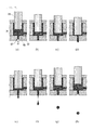
- Fig. 9(a) illustrates an initial state when the discharging operation starts.
- a front end portion 31 of the plunger is located at an operation start position which is farthest from a discharging path 12 during a series of discharging operations.
- a discharging port 11 side of the discharging path 12 may be in a state where a very small amount of open air (air) is sucked.
- Fig. 9 (b) illustrates a state where the plunger is caused to move forward from the operation start position of the plunger in Fig. 9(a) and the liquid material inside the discharging path 12 is caused to reach the discharging port (side end surface of the discharging port of the discharging path 12).
- Fig. 9(c) illustrates a state where the plunger is caused to further move forward from the position of the plunger in Fig. 9(b) . In this state, the liquid material reaching the discharging port is extracted outward from the discharging port without being divided.
- Fig. 9(d) illustrates a state where the plunger is stopped at the most forward movement position after the plunger is caused to further move forward from the position of the plunger in Fig. 9(c) .
- an amount of the liquid material required for forming a droplet having a desired size is extracted outward from the discharging port 11.
- Fig. 9 (e) illustrates a state where the plunger is caused to move slightly rearward from the position (most forward movement position) of the plunger in Fig. 9(d) . If the plunger moves rearward, a volume ratio of the plunger occupying the inside of the liquid chamber 50 decreases, thereby applying a force to the liquid material inside the discharging path 12 and the liquid material which is present outside the discharging port 11 in a direction toward the inside of the liquid chamber 50.
- the inertia force acts on the liquid material extracted from the discharging port in the forward movement direction of the plunger, the force is applied in the rearward movement direction of the plunger, and thus a droplet starts to be formed (subjected to cutting action in a portion in the vicinity of the discharging port).
- Fig. 9 (f) illustrates a state where the plunger is caused to further move rearward from the position of the plunger in Fig. 9(e) . If the plunger further moves rearward, the cutting action becomes stronger with respect to the liquid material extracted from the discharging port 11. In this manner, the liquid material extracted from the discharging port 11 which is continuous from the discharging path 12 is divided at a portion in the vicinity of the discharging port, thereby forming a droplet.
- Fig. 9 (g) illustrates a state where the plunger is caused to further move rearward from the position of the plunger in Fig. 9(f) .
- the liquid material remaining on the discharging path 12 side is sucked into the discharging path 12 by the rearward movement of the plunger.
- the discharging port 11 side of the discharging path 12 In preparation for subsequent discharging, it is preferable to leave the discharging port 11 side of the discharging path 12 in a state where a very small amount of open air (air) is sucked. That is, it means a state where the gas-liquid interface is present inside the discharging path 12. In this manner, it is possible to prevent the liquid material from being dried, and additionally, it is possible to prevent contamination of the surrounding environment which is caused by liquid dripping during standby time in the discharging operation. At this time, attention is required to be paid so that the open air (air) is not sucked into the liquid chamber 50 through the discharging path 12.
- Fig. 9 (h) illustrates a state where the plunger is caused to further move rearward from the position of the plunger in Fig. 9(g) and is caused to reach an operation end position.
- Figs. 9 (a) to 9 (h) illustrate a series of operations for forming one droplet.
- the position of the plunger when one-time discharging is completed is a position further rearward than the most forward movement position.
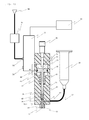
- An apparatus of Example 1 discharges the liquid material through the discharging port 11 by causing the plunger (piston 33) biased in the rearward movement direction by a spring 47 to move forward using compressed air supplied from a pressure supply source 94.
- a configuration of the apparatus in Example 1 will be first described, and then an operation will be described.
- Fig. 1 is a configuration diagram of the apparatus in Example 1.
- a main body 71 is a block-shaped member, and internally has a piston chamber 49 which is a pressurizing chamber.
- a piston 33 forming a rear end portion of the plunger is arranged in the piston chamber 49 so as to be vertically slidable.
- the piston 33 divides the piston chamber 49 into a front piston chamber 43 and a rear piston chamber 44.
- a sealing member A35 is formed in an annular shape on a side surface of the piston 33. This allows the front piston chamber 43 and the rear piston chamber 44 to hold air-tightness.
- the compressed air is supplied to the rear piston chamber 44 from an electromagnetic switching valve 72.
- the movement speed of the plunger is proportional to a magnitude of the pressure of the air supplied to the rear piston chamber 44.
- the electromagnetic switching valve 72 communicates with the pressure supply source 94 supplying the compressed air, via a pressure regulator (regulator) 95.
- the pressure regulator 95 is configured to have a pressure reducing valve or a combination of the pressure reducing valve and a buffer tank. Based on a command from a control unit 90, the electromagnetic switching valve 72 is operated so as to switch between a first position where the pressure regulator 95 and the rear piston chamber 44 communicate with each other and a second position where the rear piston chamber 44 and the external environment (atmosphere) communicate with each other.
- the electromagnetic switching valve 72 is directly fixed to the main body 71, but may be arranged at a position away from the main body 71 via a tube (pumping tube) or the like.
- a rear stopper 42 which comes into contact with a rear contact portion 34 which is a rear end of the piston 33, and which determines the most rearward movement position of the piston 33 is arranged in the rear piston chamber 44.
- the rear stopper 42 is connected to a micrometer 46 which is arranged by being inserted into a rear end portion of the main body 71, thereby functioning as a stroke adjustment mechanism. That is, a position of a tip of the rear stopper 42 is vertically moved by turning around the micrometer 46. In this manner, it is possible to adjust the stroke of the plunger.
- the front piston chamber 43 is a space for communicating with a spring chamber 48.
- a spring 47 is arranged in the front piston chamber 43 and the spring chamber 48.
- a rod portion 30 of the plunger is inserted into the spring 47.
- the spring 47 is a compression coil spring, one end of which is in contact with or is fixed to a bottom portion of the spring chamber 47, and the other end of which is in contact with or is fixed to the piston 33.
- the spring 47 When the electromagnetic switching valve 72 is located at the first position, the spring 47 is compressed by the piston 33 to be in a state of storing elastic energy. If the position of the electromagnetic switching valve 72 is switched over to the second position, the elastic energy of the spring 47 which is stored by the compression causes the piston 33 to move rearward. This prompts the rear piston chamber 44 to eject the compressed air. Therefore, it is possible to quickly proceed to a subsequent discharging operation, and thus, it is possible to shorten a tact time.
- the rod portion 30 of the plunger is inserted into an insertion hole 51 of the main body 71.
- the rod portion 30 is configured to have a large-diameter portion and a small-diameter portion.
- the small-diameter portion is inserted into a guide 45, and this guides the plunger moving forward and rearward so as not to be shaken rightward and leftward.
- a tip of the small-diameter portion configures the front end portion 31 moving forward and rearward inside the liquid chamber 50.
- an inner bottom surface of the liquid chamber 52 having the discharging path 12 configures a valve seat.
- the front end portion 31 comes into contact with a bottom portion of the liquid chamber 50, thereby dividing the liquid material and causing the liquid material to be discharged through the discharging port 11.
- the most forward movement position of the plunger in Example 1 is determined by the front end portion 31 coming into contact with the inner bottom surface of the liquid chamber 52.
- the liquid chamber 50 communicates with a liquid feeding path 52, and the liquid material is supplied from a storage container 80 to the liquid chamber 50 via a liquid feeding tube 53.
- the liquid material inside the storage container 80 is supplied into the liquid chamber 50 by its own weight without being pressurized, but the storage container 80 may be configured to be pressurized as in Example 2 described below.
- the liquid feeding tube 53 can fluidly connect the main body and the storage container, any member can be used and a non-tubular shape may be employed.
- a sealing member B36 prevents the liquid material inside the liquid chamber 50 from entering the insertion hole 51.
- the liquid chamber 50 is filled with the liquid material. That is, the liquid material is supplied from the storage container 80 to the liquid chamber 50 via the liquid feeding tube 53 and the liquid feeding path 52, and the liquid chamber 50 is filled with the liquid material up to the discharging port 11.
- the electromagnetic switching valve 72 is located at the first position where the pressure regulator 95 and the rear piston chamber 44 communicate with each other so as to cause the plunger to move forward. Then, the front end portion 31 of the plunger is brought into contact with the inner bottom surface of the liquid chamber 52 to close the discharging port 11.
- the position of the electromagnetic switching valve 72 is switched over to the second position where the rear piston chamber 44 and the open air (atmosphere) communicate with each other.
- the air inside the rear piston chamber 44 is ejected outward, the spring 47 presses the piston 33 upward, and the front end portion 31 of the plunger is separated from the inner bottom surface of the liquid chamber 50.
- the piston 33 rises until the rear contact portion 34 comes into contact with the rear stopper 42, and then stops.
- the liquid material flows into the liquid chamber 50 from the storage container 80.
- the force applied by the compressed air supplied to the rear piston chamber 44 to the piston 33 prevails against the biasing force of the spring 47, thereby causing the plunger to move forward. If the front end portion 31 of the plunger comes into contact with the inner bottom surface of the liquid chamber 50, the movement of the plunger is stopped, the liquid material flowing out from the discharging port 11 is divided, and the liquid material is discharged in a flying way.
- the above-described operation is an operation for one-time discharging.
- the position of the electromagnetic switching valve 72 is switched over to the second position again, and the liquid chamber 50 is refilled with the liquid material. Then, second-time discharging is performed by switching the position of the electromagnetic switching valve 72 over to the first position. Subsequently, this operation is continuously repeated, thereby enabling the liquid material to be continuously discharged.
- Example 1 it is possible to more easily adjust the forward movement speed of the plunger by adjusting the pressure of the compressed air while fixing the stroke of the plunger.
- An apparatus of Example 2 is different from the apparatus of Example 1 in that the front end portion 31 of the plunger does not come into contact with the inner bottom surface of the liquid chamber 50 when the liquid material is discharged. That is, the apparatus of Example 2 includes a plunger position determination mechanism for determining the position of the front end portion 31 of the plunger, and discharges the liquid material in a droplet state after applying the inertia force to the liquid material by causing the plunger to move forward and stop the forward movement in a state where the front end portion of the plunger and an inner wall of the liquid chamber are not in contact with each other.
- Fig. 2 is a configuration diagram of the apparatus in Example 2.
- this apparatus by using a fixing screw 54 inserted into a slot 55 disposed in the main body 71, it is possible to adjust the position of the main body 71 with respect to a base 70. That is, the main body 71 is movable with respect to the base 70 by loosening the fixing screw 54, the position of the main body 71 is adjusted by a position determining member 40, and the fixing screw 54 is fastened to fix the main body 71 to the base 70.
- the position determining member 40 is arranged between the main body 71 and a discharging unit 57.
- the position determining member 40 is configured to have a front projection having a cylindrical shape, a rear projection having a cylindrical shape and a disk-shaped rotary knob which connects these projections.
- a through hole is disposed on a central axis of the position determining member 40, and the rod portion 30 of the plunger is inserted into the through hole.
- the front projection has the cylindrical shape and has a screw groove for screwing to a rear recess whose outer peripheral surface includes the discharging unit 57.
- a surface of the rotary knob is configured to have a scale corresponding to a position display member (movement amount check member) so as to check a rotated angle from outside. It is possible to quantitatively check a change in the position of the position determining member 40 by using the rotary knob.
- the rear projection is inserted into a recess disposed in the main body 71.
- the piston 33 has a front contact portion 32 protruding forward and a rear contact portion 34 protruding rearward.
- the front contact portion 32 comes into contact with the inner bottom surface of the front piston chamber 43, thereby determining the most forward movement position of the plunger. That is, the inner bottom surface of the front piston chamber 43 configures a front stopper 56.
- the position of the position determining member 40 it is possible to adjust a distance between the front end portion 31 and the inner bottom surface of the liquid chamber 50 at the most forward movement position of the plunger. That is, the front contact portion 32, the front stopper 56 and the position determining member 40 configure the position determining mechanism for determining the most forward movement position of the plunger.
- a nozzle member 10 is screwed to and inserted into the front end portion of the discharging unit 57.
- the liquid material is supplied from the storage container 80 to the liquid chamber 50 inside the nozzle member 10.
- the compressed air whose pressure is regulated to be a desired pressure by a pressure regulator B96 is supplied to the storage container 80.
- the pressure regulator B96 is configured to have a pressure reducing valve or a combination of the pressure reducing valve and a buffer tank.
- the control unit 90 can change a supply pressure depending on the properties of the liquid material. For example, when discharging the high viscosity material, a relatively high pressure is supplied.
- the front end portion of the plunger does not come into contact with the valve seat. Therefore, the rod of the plunger or the valve seat is not worn. In addition, it is possible to excellently discharge the liquid material even a filler-contained liquid material such as a cream solder.
- An apparatus of Example 3 includes a moving member 41 which varies a size of the piston chamber 49, below (in front of) the piston chamber 49.
- the apparatus of Example 3 is different from the apparatus of Example 2 in that there are provided an electromagnetic switching valve B98 which applies a desired pressure to the storage container 80 and a pressure reducing valve B99.
- Fig. 3 is a configuration diagram of the apparatus in Example 3.
- the main body 71 of this example is configured to have a vertical length which is sufficiently short as compared to the base 70 (length of the main body 71 is half of the length of the base 70 or shorter), and has a space in which a bottom surface configuring the piston chamber 49 is open.
- the piston 33 arranged to be slidable in the space inside the main body 71 has a sealing member A35 on a side peripheral surface, thereby forming the air-tight rear piston chamber 44.
- a screw groove is formed on an inner periphery of a lower end portion of the main body 71, and the moving member 41 having a screw groove on an outer periphery is screwed and inserted.
- the piston chamber 49 It is possible to change the size of the piston chamber 49 by using a screw mechanism (position adjustment mechanism) configured to have the outer peripheral screw groove of the moving member 41 and the inner peripheral screw grove of the lower end portion of the main body 71.
- a screw mechanism position adjustment mechanism
- the piston chamber 49 is narrowed by rotating and tightening the moving member 41 in a forward direction, and the piston chamber 49 is widened by loosening and rotating the moving member 41 in a reverse direction.
- the spring 47 is inserted into a through hole in a vertical direction of the moving member 41. In the spring 47, one end thereof is in contact with or is fixed to the piston 33, and the other end thereof is in contact with or is fixed to the discharging unit 57.
- the piston 33 of this example also has the front contact portion 32 protruding forward.
- the front contact portion 32 comes into contact with a rear end surface of the moving member 41, thereby determining the most forward movement position of the plunger. That is, the rear end surface of the moving member 41 configures the front stopper 56. Then, the front contact portion 32, the front stopper 56 and the moving member 41 configure the position determining mechanism for determining the most forward movement position of the plunger.
- the moving member 41 is largely loosened to move downward, the contact portion 32 of the piston 33 is enabled to largely move forward. In this manner, it is possible to determine the most forward movement position where the front end portion 31 of the plunger comes into contact with the inner bottom surface of the liquid chamber 50. If the moving member 41 is tightened and the most forward movement position of the plunger is caused to move rearward from this state, it is possible to determine the most forward movement position where the front end portion 31 of the plunger does not come into contact with the inner bottom surface of the liquid chamber 50.
- the nozzle member 10 is screwed to and inserted into the front end portion of the discharging unit 57.
- the liquid material is supplied from the storage container 80 to the liquid chamber 50 inside the nozzle member 10.
- the compressed air whose pressure is regulated by the pressure reducing valve B99 is supplied to the storage container 70 via the electromagnetic switching valve B98.
- the electromagnetic switching valve B98 is operated based on a command from the control unit 90, and switches between a position where the pressure reducing valve B99 and the storage container 80 communicate with each other and a position where the storage container 80 and the open air communicate with each other.
- the storage container 80 is replaced by another storage container, it is possible to prevent unnecessary consumption of the compressed air by switching the position of the electromagnetic switching valve B98 over to the position where the storage container 80 and the open air communicate with each other.
- Example 3 According to the apparatus of Example 3 as described above, it is possible to achieve the same effect as that of Example 2. In addition, when the storage container is replaced by another storage container, it is possible to prevent unnecessary consumption of the compressed air.
- An apparatus of Example 4 is different from the apparatus of Example 3 in that there are provided a pressure regulator (pressure reducing valve) 91, a buffer tank 92 and a pressure intensifier 93 instead of the pressure regulator 95.
- a pressure regulator pressure reducing valve
- the movement speed of the plunger is proportional to the magnitude of the pressure of the air supplied to the rear piston chamber 44, it is necessary to supply highly compressed air in order to move the plunger fast. Therefore, in this example, instead of the pressure regulator 95 of Example 3, the pressure reducing valve 91, the buffer tank 92 and the pressure intensifier 93 are disposed.
- Fig. 4 is a configuration diagram of the apparatus in Example 4.
- the pressure reducing valve 91 is a pressure reducing valve for eliminating variations in the pressure of the compressed air whose pressure is intensified, adjusts the intensified compressed air to have a desired pressure, and supplies the compressed air to the electromagnetic switching valve 72.
- the pressure intensifier 93 intensifies the pressure of the air supplied from the pressure supply source 94.
- the buffer tank 92 arranged in the flow path which allows the pressure intensifier 93 and the pressure reducing valve 91 to communicate with each other prevents occurrence of pulsations by temporarily storing the intensified compressed air.
- the buffer tank 92 may be disposed in the flow path which allows the pressure reducing valve 91 and the electromagnetic switching valve 72 to communicate with each other.
- a first buffer tank may be disposed in the flow path which allows the pressure intensifier 93 and the pressure reducing valve 91 to communicate with each other
- a second buffer tank may be disposed in the flow path which allows the pressure reducing valve 91 and the electromagnetic switching valve 72 to communicate with each other.
- the apparatus has a configuration where the stroke of the plunger and the biasing force of the spring 47 are simultaneously adjusted by adjusting the distance of the moving member 41 with respect to the main body 71. That is, if the moving member 41 is moved downward with respect to the main body 71, the most forward movement position of the plunger moves forward, and the biasing force of the spring is weakened. If the moving member 41 is moved upward with respect to the main body 71, the most forward movement position of the plunger moves rearward, and the biasing force of the spring is strengthened.
- the apparatus of this example includes the pressure reducing valve 91 which regulates the pressure of the intensified compressed air and the buffer tank 92 which temporarily stores the intensified compressed air. Therefore, it is possible to stably supply the highly compressed air required for moving the plunger fast.
- An apparatus of Example 5 is different from those of the respective examples as described above in that there is provided a mechanism (biasing force adjustment mechanism) which adjusts the biasing force of the spring by independently adjusting the stroke of the plunger.
- a controller 97 obtained by aggregating the electromagnetic switching valve, the pressure regulator, the pressure intensifier and the control unit.
- the apparatus of this example is similar to that of Example 3 in that the vertical length of the main body 71 is sufficiently short as compared to the base 70, but is different from that of Example 3 in that the front contact portion 32 is disposed in the rod portion 30 of the plunger.
- Fig. 5 is a configuration diagram of the apparatus in Example 5.
- the main body 71 of this example is configured to have the vertical length which is sufficiently short as compared to the base 70 (length of the main body 71 is half of the length of the base 70 or shorter), and has a space in which a bottom surface configuring the piston chamber 49 is open.
- the piston 33 arranged to be slidable in the space inside the main body 71 has the sealing member A35 on the side peripheral surface, thereby forming the air-tight rear piston chamber 44.
- a screw groove is formed on the inner periphery of the lower end portion of the main body 71, and the moving member 41 having a screw groove on the outer periphery is screwed and inserted.
- Example 4 is similar to Example 3 and Example 4 in that the screw mechanism which can adjust the distance between the moving member 41 and the main body 71 is provided to change the size of the piston chamber 49.
- this example is similar to Example 4 in that the spring 47 is held by being interposed between the rear end surface of the moving member 41 and the front end surface of the piston 33.
- this example is different from Example 4 in that the most forward movement position of the plunger is determined by the position determining member 40.
- the force clamping the spring 47 increases, and if the moving member 41 is rotated in the reverse direction to proceed in the direction of the nozzle member 10, the force clamping the spring 47 decreases. That is, the elastic force of the spring 47 which causes the moving member 41 to regulate the rearward movement speed of the plunger is adjusted. In this manner, it is possible to adjust the rearward movement speed of the plunger by independently adjusting the stroke of the plunger.
- the rod portion 30 of the plunger is configured to have a large-diameter portion and a small-diameter portion.
- the small-diameter portion is inserted into the guide 45 arranged below the moving member 41, and is guided so as not to be shaken rightward and leftward.
- the front end surface of the large-diameter portion of the rod portion 30 forms the front contact portion 32.
- the most forward movement position of the plunger is determined by the front contact portion 32 coming into contact with the front stopper 56 which forms the rear end portion of the position determining member 40.
- the position determining member 40 is arranged between the guide 45 and the discharging unit 57.
- the position determining member 40 is configured to have a front projection having a cylindrical shape, a rear projection having a cylindrical shape and a disk-shaped rotary knob which connects these projections.
- a through hole is disposed on a central axis of the position determining member 40, and the small-diameter portion of the rod portion 30 of the plunger is inserted into the through hole.
- Example 5 it is possible not only to adjust the most forward movement position of the plunger, but also to adjust the rearward movement speed of the plunger by adjusting the elastic force of the spring 47.
- An apparatus of Example 6 is different from the apparatus of Example 5 in that there is provided a flow control valve 73. That is, in addition to the mechanism for adjusting the biasing force of the spring 47 using the moving member 41, the apparatus of Example 6 can adjust the rearward movement speed of the piston 33 using the flow control valve 73.
- Fig. 6 is a configuration diagram of the apparatus in Example 6.
- the flow control valve 73 is connected to an air ejection port 76 of the electromagnetic switching valve 72. If the electromagnetic switching valve 72 is located at the second position where the rear piston chamber 44 and the air ejection port 76 communicate with each other, the compressed air inside the rear piston chamber 44 is ejected from the air ejection port 76. At this time, it is possible to control the rearward movement speed of the plunger by controlling the flow rate of the air ejection using the flow control valve 73.
- Example 7 discloses an apparatus including the flow control valve 73 at a position different from that of the apparatus in Example 6.
- Fig. 7 is a configuration diagram of the apparatus in Example 7.
- the flow control valve 73 is arranged in an opening disposed on a side of the front piston chamber 43.
- a rear portion of the moving member 41 configures a wall surface of the front piston chamber 43.
- a sealing member C37 is disposed in a through hole (hole into which the rod portion 30 is inserted) disposed on the central axis of the moving member 41, thereby allowing the front piston chamber 43 to be air-tight and enhancing an adjustment effect achieved by the flow control valve 73.
- Example 7 it is possible to adjust the rearward movement speed of the piston 33 by controlling a deflection degree of the spring 47 using the moving member 41, and it is possible to adjust the rearward movement speed of the piston 33 by controlling the flow rate of the air flowing in the front piston chamber 43.
- a second flow control valve may be disposed in the air ejection port 76 of the electromagnetic switching valve 72, and the rearward movement speed of the plunger may be controlled by two flow control valves.
- Example 8 discloses an apparatus which employs a tension coil spring as the spring (elastic body) 47.
- Fig. 8 is a configuration diagram of the apparatus in Example 8.
- the spring 47 which is the tension coil spring is arranged inside the rear piston chamber 44, and is held by being interposed between the piston 33 and the moving member 41. That is, in the spring 47, one end thereof is attached to the rear portion of the piston 33 and the other end is attached to the front portion of the moving member 41, thereby applying the biasing force against the piston 33 in the rearward movement direction.
- the moving member 41 is screwed to and inserted into the upper portion (rear portion) of the main body 71, and the lower portion (front portion) of the moving member 41 forms a wall surface of the rear piston chamber 44. It is possible to change the size of the piston chamber 49 by using the screw mechanism (position adjustment mechanism) configured to have the outer peripheral screw groove of the moving member 41 and the inner peripheral screw groove of the lower end portion of the main body 71.
- a sealing member D38 is disposed in a through hole disposed on the central axis of the moving member 41, and a sealing member E39 is disposed between the main body 71 and the moving member 41, thereby allowing the rear piston chamber 44 to be air-tight.
- the micrometer 46 is inserted into the through hole disposed on the central axis of the moving member 41.
- the rear stopper 42 connected to the micrometer 46 is relatively moved with respect to the moving member 41 and comes into contact with the piston 33, thereby determining the most rearward movement position.
- the movement distance (stroke) of the plunger ranges from the position where the rear contact portion 34 comes into contact with the rear stopper 42 to the position where the front contact portion 32 comes into contact with the front stopper 56. It is possible to adjust the stroke of the plunger by appropriately adjusting the position of the moving member 41, the degree of rotation of the micrometer 46 and the position of the position determining member 40. The above-described point is the same as those of other examples.
- the position of the electromagnetic switching valve 72 is switched over to the first position to supply the compressed air to the rear piston chamber 44.
- a forward movement force prevailing against the biasing force of the spring 47 is applied to the piston 33 so as to cause the plunger to move forward, thereby performing the discharging.
- a liquid material discharge apparatus and a method for the same according to the present invention is suitable for an operation which discharges a very small amount of liquid material with high accuracy.
- the present invention is preferably applied to a sealing coating apparatus or a liquid crystal dropping apparatus in a liquid crystal panel manufacturing process, and an apparatus for applying a solder paste to a printed board.
- the present invention can be applied to both of a method of causing a plunger (valve body) to collide with a valve seat (inner wall of liquid chamber) so as to discharge in a flying way a liquid material through a nozzle, and a method of causing the plunger to move fast and rapidly stopping the plunger without being collided with the valve seat so as to apply an inertia force to the liquid material and to discharge in a flying way the liquid material through the nozzle.
Priority Applications (1)
| Application Number | Priority Date | Filing Date | Title |
|---|---|---|---|
| PL12838442T PL2764925T3 (pl) | 2011-10-07 | 2012-10-05 | Urządzenie do odprowadzania materiału ciekłego i sposób |
Applications Claiming Priority (2)
| Application Number | Priority Date | Filing Date | Title |
|---|---|---|---|
| JP2011222468A JP5986727B2 (ja) | 2011-10-07 | 2011-10-07 | 液体材料の吐出装置および方法 |
| PCT/JP2012/075956 WO2013051697A1 (fr) | 2011-10-07 | 2012-10-05 | Appareil et procédé d'évacuation de matériau liquide |
Publications (3)
| Publication Number | Publication Date |
|---|---|
| EP2764925A1 true EP2764925A1 (fr) | 2014-08-13 |
| EP2764925A4 EP2764925A4 (fr) | 2015-07-29 |
| EP2764925B1 EP2764925B1 (fr) | 2019-02-27 |
Family
ID=48043850
Family Applications (1)
| Application Number | Title | Priority Date | Filing Date |
|---|---|---|---|
| EP12838442.7A Active EP2764925B1 (fr) | 2011-10-07 | 2012-10-05 | Appareil et procédé d'évacuation de matériau liquide |
Country Status (10)
| Country | Link |
|---|---|
| US (2) | US9260234B2 (fr) |
| EP (1) | EP2764925B1 (fr) |
| JP (1) | JP5986727B2 (fr) |
| KR (1) | KR102012303B1 (fr) |
| CN (2) | CN106984490B (fr) |
| MY (1) | MY170835A (fr) |
| PL (1) | PL2764925T3 (fr) |
| SG (2) | SG10201607814PA (fr) |
| TW (1) | TWI592216B (fr) |
| WO (1) | WO2013051697A1 (fr) |
Cited By (1)
| Publication number | Priority date | Publication date | Assignee | Title |
|---|---|---|---|---|
| WO2016032746A1 (fr) | 2014-08-28 | 2016-03-03 | Nordson Corporation | Module de distribution de jet sans impact et procédé |
Families Citing this family (30)
| Publication number | Priority date | Publication date | Assignee | Title |
|---|---|---|---|---|
| WO2011071888A1 (fr) * | 2009-12-08 | 2011-06-16 | Nordson Corporation | Système d'entraînement à amplification de force, distributeur à jet et procédé de distribution d'un fluide |
| JP5986727B2 (ja) * | 2011-10-07 | 2016-09-06 | 武蔵エンジニアリング株式会社 | 液体材料の吐出装置および方法 |
| EP2972130A4 (fr) * | 2013-03-14 | 2016-12-07 | The Alfred E Mann Found For Scient Res | Capteur microfluidique de débit d'écoulement |
| CN107214044B (zh) * | 2013-05-20 | 2019-09-27 | 日本电产增成株式会社 | 液剂吐出装置 |
| JP6381902B2 (ja) * | 2013-12-13 | 2018-08-29 | Ntn株式会社 | 塗布針ホルダ |
| KR101610197B1 (ko) * | 2014-11-18 | 2016-04-08 | 주식회사 프로텍 | 압전 공압 밸브 구동형 디스펜싱 펌프 및 이를 이용한 용액 디스펜싱 방법 |
| CN104391403A (zh) * | 2014-12-05 | 2015-03-04 | 京东方科技集团股份有限公司 | 一种液晶泵及应用该液晶泵的滴下方法 |
| CN104588232B (zh) * | 2015-01-15 | 2017-03-08 | 深圳市轴心自控技术有限公司 | 喷射阀及使用该喷射阀的点胶系统 |
| CN104588233B (zh) * | 2015-01-15 | 2017-03-08 | 深圳市轴心自控技术有限公司 | 喷射阀及具有该喷射阀的点胶系统 |
| JP6452147B2 (ja) * | 2015-01-19 | 2019-01-16 | 武蔵エンジニアリング株式会社 | 液体材料吐出装置 |
| KR101674425B1 (ko) * | 2015-03-05 | 2016-11-09 | 김진수 | 수지 도포장치 |
| CN105149167B (zh) * | 2015-10-16 | 2017-09-01 | 漳州职业技术学院 | 一种负压反馈回吸顶针式点胶阀 |
| KR101740146B1 (ko) * | 2015-10-30 | 2017-05-26 | 주식회사 프로텍 | 펌프 위치 피드백 방식 디스펜서 및 디스펜싱 방법 |
| JP6615634B2 (ja) | 2016-02-22 | 2019-12-04 | 武蔵エンジニアリング株式会社 | 増圧回路を備える液体材料吐出装置 |
| CN106076693A (zh) * | 2016-07-15 | 2016-11-09 | 苏州锡友微连电子科技有限公司 | 一种锡膏喷射阀 |
| JP6285510B2 (ja) * | 2016-08-08 | 2018-02-28 | 武蔵エンジニアリング株式会社 | 液体材料の吐出装置および方法 |
| JP6778426B2 (ja) * | 2016-09-20 | 2020-11-04 | 武蔵エンジニアリング株式会社 | 液体材料吐出装置 |
| JP6772725B2 (ja) * | 2016-09-29 | 2020-10-21 | セイコーエプソン株式会社 | 流体吐出装置および流体を吐出する方法 |
| JP2018051478A (ja) | 2016-09-29 | 2018-04-05 | セイコーエプソン株式会社 | 流体吐出装置および流体を吐出する方法 |
| JP2018051479A (ja) * | 2016-09-29 | 2018-04-05 | セイコーエプソン株式会社 | 流体吐出装置および流体を吐出する方法 |
| KR102504663B1 (ko) * | 2017-04-28 | 2023-02-27 | 무사시 엔지니어링 가부시키가이샤 | 케이블 유닛, 이것을 구비하는 액체 재료 공급 장치 및 도포 장치 |
| JP6349480B1 (ja) | 2017-05-25 | 2018-06-27 | 武蔵エンジニアリング株式会社 | 液体材料塗布装置および液体材料塗布方法 |
| US10801493B2 (en) * | 2017-12-14 | 2020-10-13 | William E. Howseman, Jr. | Positive displacement reciprocating pump assembly for dispensing predeterminedly precise amounts of fluid during both the up and down strokes of the pump piston |
| US11446696B2 (en) * | 2018-02-02 | 2022-09-20 | Threebond Co., Ltd. | Discharge device and liquid supply method |
| KR102014701B1 (ko) * | 2019-04-16 | 2019-08-27 | (주)한빛산업 | 2차전지 전극코팅용 가변 액츄에이터 장치 |
| JPWO2021131327A1 (fr) * | 2019-12-24 | 2021-07-01 | ||
| US20220234291A1 (en) * | 2021-01-22 | 2022-07-28 | Formlabs, Inc. | Material dispensing pump for additive fabrication |
| CN115318551B (zh) * | 2021-05-11 | 2024-03-29 | 三赢科技(深圳)有限公司 | 一种点胶装置 |
| CN115672597A (zh) * | 2021-07-27 | 2023-02-03 | 长鑫存储技术有限公司 | 一种喷涂装置及喷涂方法 |
| CN114411519B (zh) * | 2022-03-10 | 2023-11-24 | 济南市市政工程设计研究院(集团)有限责任公司 | 一种沥青路面防冻修复一体化装置 |
Family Cites Families (26)
| Publication number | Priority date | Publication date | Assignee | Title |
|---|---|---|---|---|
| CH556692A (de) * | 1971-02-15 | 1974-12-13 | Roth Oscar | Spritzpistole zum aufspritzen von leim. |
| US4030640A (en) * | 1975-11-10 | 1977-06-21 | Indicon Inc. | Method and apparatus for dispensing viscous materials |
| US4465212A (en) * | 1980-05-09 | 1984-08-14 | Nordson Corporation | Liquid dispensing device |
| US4784582A (en) * | 1987-10-02 | 1988-11-15 | Creative Automation Company | Fluid dispensing pump |
| US5022556A (en) * | 1989-10-25 | 1991-06-11 | Raytheon Company | Programmable volume dispensing apparatus |
| US5467899A (en) * | 1994-02-08 | 1995-11-21 | Liquid Control Corporation | Dispensing device for flowable materials |
| US6253957B1 (en) * | 1995-11-16 | 2001-07-03 | Nordson Corporation | Method and apparatus for dispensing small amounts of liquid material |
| US5747102A (en) | 1995-11-16 | 1998-05-05 | Nordson Corporation | Method and apparatus for dispensing small amounts of liquid material |
| US6267266B1 (en) * | 1995-11-16 | 2001-07-31 | Nordson Corporation | Non-contact liquid material dispenser having a bellows valve assembly and method for ejecting liquid material onto a substrate |
| US5924607A (en) * | 1996-02-16 | 1999-07-20 | Nireco Corporation | Hot melt applicator and nozzle used therefor |
| JPH11197571A (ja) * | 1998-01-12 | 1999-07-27 | Nordson Kk | 吐出ガンの弁機構の開閉速度制御方法及び装置並びに液状体の吐出塗布方法 |
| US6105832A (en) * | 1998-05-11 | 2000-08-22 | Beck; James L. | High speed, no stringing, hot melt adhesive dispensing head |
| JP4681126B2 (ja) * | 2000-12-13 | 2011-05-11 | 富士機械製造株式会社 | 高粘性流体塗布装置 |
| JP4663894B2 (ja) | 2001-03-27 | 2011-04-06 | 武蔵エンジニアリング株式会社 | 液滴の形成方法および液滴定量吐出装置 |
| JP2003025183A (ja) * | 2001-07-12 | 2003-01-29 | Enshu Ltd | 工具ホルダの潤滑油吐出量制御方法とその装置 |
| US6494347B1 (en) * | 2001-11-05 | 2002-12-17 | Kuo-Chung Yeh | Grease gun having automatic continuous feeding device |
| US7018477B2 (en) * | 2002-01-15 | 2006-03-28 | Engel Harold J | Dispensing system with a piston position sensor and fluid scanner |
| KR101499597B1 (ko) * | 2007-03-08 | 2015-03-06 | 무사시 엔지니어링 가부시키가이샤 | 액적 토출 장치 및 방법 |
| JP2010022881A (ja) * | 2007-03-30 | 2010-02-04 | Musashi Eng Co Ltd | 液材吐出装置および液材吐出方法 |
| JP2009219993A (ja) | 2008-03-14 | 2009-10-01 | Riso Kagaku Corp | 粘性流体吐出装置及び粘性流体吐出方法 |
| US20100055299A1 (en) * | 2008-09-02 | 2010-03-04 | Nscrypt, Inc. | Dispensing patterns including lines and dots at high speeds |
| JP2010253439A (ja) * | 2009-04-28 | 2010-11-11 | Riso Kagaku Corp | 液剤吐出方法及び液剤吐出装置 |
| WO2011071888A1 (fr) | 2009-12-08 | 2011-06-16 | Nordson Corporation | Système d'entraînement à amplification de force, distributeur à jet et procédé de distribution d'un fluide |
| EP2523894B1 (fr) * | 2010-01-14 | 2017-08-23 | Nordson Corporation | Projection de volumes discrets de liquide à haute viscosité |
| DE102011108799A1 (de) * | 2011-07-29 | 2013-01-31 | Vermes Microdispensing GmbH | Dosiersystem und Dosierverfahren |
| JP5986727B2 (ja) * | 2011-10-07 | 2016-09-06 | 武蔵エンジニアリング株式会社 | 液体材料の吐出装置および方法 |
-
2011
- 2011-10-07 JP JP2011222468A patent/JP5986727B2/ja active Active
-
2012
- 2012-10-05 SG SG10201607814PA patent/SG10201607814PA/en unknown
- 2012-10-05 US US14/350,236 patent/US9260234B2/en active Active
- 2012-10-05 SG SG11201401318WA patent/SG11201401318WA/en unknown
- 2012-10-05 KR KR1020147011788A patent/KR102012303B1/ko active IP Right Grant
- 2012-10-05 CN CN201710014069.3A patent/CN106984490B/zh active Active
- 2012-10-05 TW TW101137057A patent/TWI592216B/zh active
- 2012-10-05 CN CN201280049422.7A patent/CN103889589B/zh active Active
- 2012-10-05 MY MYPI2014700849A patent/MY170835A/en unknown
- 2012-10-05 WO PCT/JP2012/075956 patent/WO2013051697A1/fr active Application Filing
- 2012-10-05 EP EP12838442.7A patent/EP2764925B1/fr active Active
- 2012-10-05 PL PL12838442T patent/PL2764925T3/pl unknown
-
2015
- 2015-12-31 US US14/986,517 patent/US9919336B2/en active Active
Cited By (3)
| Publication number | Priority date | Publication date | Assignee | Title |
|---|---|---|---|---|
| WO2016032746A1 (fr) | 2014-08-28 | 2016-03-03 | Nordson Corporation | Module de distribution de jet sans impact et procédé |
| EP3186016A4 (fr) * | 2014-08-28 | 2018-04-11 | Nordson Corporation | Module de distribution de jet sans impact et procédé |
| US10272463B2 (en) | 2014-08-28 | 2019-04-30 | Nordson Corporation | Non-impact jetting dispensing module and method |
Also Published As
| Publication number | Publication date |
|---|---|
| CN106984490A (zh) | 2017-07-28 |
| SG11201401318WA (en) | 2014-11-27 |
| MY170835A (en) | 2019-09-06 |
| CN106984490B (zh) | 2019-05-14 |
| US9919336B2 (en) | 2018-03-20 |
| WO2013051697A1 (fr) | 2013-04-11 |
| KR102012303B1 (ko) | 2019-08-20 |
| US20140252041A1 (en) | 2014-09-11 |
| US9260234B2 (en) | 2016-02-16 |
| PL2764925T3 (pl) | 2019-08-30 |
| TW201325736A (zh) | 2013-07-01 |
| TWI592216B (zh) | 2017-07-21 |
| US20160107188A1 (en) | 2016-04-21 |
| JP5986727B2 (ja) | 2016-09-06 |
| SG10201607814PA (en) | 2016-11-29 |
| EP2764925B1 (fr) | 2019-02-27 |
| JP2013081884A (ja) | 2013-05-09 |
| KR20140074974A (ko) | 2014-06-18 |
| EP2764925A4 (fr) | 2015-07-29 |
| CN103889589B (zh) | 2017-02-15 |
| CN103889589A (zh) | 2014-06-25 |
Similar Documents
| Publication | Publication Date | Title |
|---|---|---|
| US9919336B2 (en) | Liquid material discharge apparatus and method | |
| JP6339637B2 (ja) | 個別量の高粘性液体の噴射 | |
| TWI609722B (zh) | 液滴吐出裝置及方法 | |
| KR101715089B1 (ko) | 액체 재료 토출 방법 및 장치 | |
| US9457372B2 (en) | Viscous non-contact jetting method and apparatus | |
| KR102351754B1 (ko) | 모노 펌프에 의한 공급을 포함하는 분사 분배 시스템 및 관련 방법 | |
| WO2002076623A1 (fr) | Procede de formation de gouttelettes et dispositif de diffusion de gouttelettes a volume constant | |
| CN108698074B (zh) | 具备增压回路的液体材料吐出装置 | |
| KR101187153B1 (ko) | 액적조정방법, 액적토출방법 및 액적토출장치 | |
| JP2017127878A (ja) | 液滴塗布装置 | |
| JP6183597B2 (ja) | 液滴塗布装置 | |
| JP6285510B2 (ja) | 液体材料の吐出装置および方法 | |
| JP2022510639A (ja) | 投与システム、および投与システムを制御する方法 | |
| JP2015221442A (ja) | 液滴吐出装置および方法 | |
| CN111936239A (zh) | 液体材料吐出装置 | |
| JPH10277457A (ja) | 接着剤塗布装置 | |
| KR20220128437A (ko) | 공급 도관 액추에이터를 갖는 토출 장치들 | |
| KR20120106713A (ko) | 액체 재료 토출 방법, 장치 및 프로그램을 기억한 기억 매체 | |
| US6558136B1 (en) | Micropump underpressure control device | |
| KR20220127920A (ko) | 가요성 토출 노즐을 갖는 토출 장치들 |
Legal Events
| Date | Code | Title | Description |
|---|---|---|---|
| PUAI | Public reference made under article 153(3) epc to a published international application that has entered the european phase |
Free format text: ORIGINAL CODE: 0009012 |
|
| 17P | Request for examination filed |
Effective date: 20140428 |
|
| AK | Designated contracting states |
Kind code of ref document: A1 Designated state(s): AL AT BE BG CH CY CZ DE DK EE ES FI FR GB GR HR HU IE IS IT LI LT LU LV MC MK MT NL NO PL PT RO RS SE SI SK SM TR |
|
| DAX | Request for extension of the european patent (deleted) | ||
| RA4 | Supplementary search report drawn up and despatched (corrected) |
Effective date: 20150701 |
|
| RIC1 | Information provided on ipc code assigned before grant |
Ipc: B05C 5/02 20060101ALI20150625BHEP Ipc: H05K 3/34 20060101ALI20150625BHEP Ipc: B05D 1/26 20060101ALI20150625BHEP Ipc: B65D 83/00 20060101ALI20150625BHEP Ipc: B05C 11/10 20060101ALI20150625BHEP Ipc: B05C 5/00 20060101AFI20150625BHEP |
|
| GRAP | Despatch of communication of intention to grant a patent |
Free format text: ORIGINAL CODE: EPIDOSNIGR1 |
|
| STAA | Information on the status of an ep patent application or granted ep patent |
Free format text: STATUS: GRANT OF PATENT IS INTENDED |
|
| INTG | Intention to grant announced |
Effective date: 20180907 |
|
| GRAS | Grant fee paid |
Free format text: ORIGINAL CODE: EPIDOSNIGR3 |
|
| GRAA | (expected) grant |
Free format text: ORIGINAL CODE: 0009210 |
|
| STAA | Information on the status of an ep patent application or granted ep patent |
Free format text: STATUS: THE PATENT HAS BEEN GRANTED |
|
| AK | Designated contracting states |
Kind code of ref document: B1 Designated state(s): AL AT BE BG CH CY CZ DE DK EE ES FI FR GB GR HR HU IE IS IT LI LT LU LV MC MK MT NL NO PL PT RO RS SE SI SK SM TR |
|
| REG | Reference to a national code |
Ref country code: GB Ref legal event code: FG4D |
|
| REG | Reference to a national code |
Ref country code: CH Ref legal event code: EP |
|
| REG | Reference to a national code |
Ref country code: AT Ref legal event code: REF Ref document number: 1100565 Country of ref document: AT Kind code of ref document: T Effective date: 20190315 |
|
| REG | Reference to a national code |
Ref country code: IE Ref legal event code: FG4D |
|
| REG | Reference to a national code |
Ref country code: DE Ref legal event code: R096 Ref document number: 602012057257 Country of ref document: DE |
|
| REG | Reference to a national code |
Ref country code: CH Ref legal event code: NV Representative=s name: NOVAGRAAF INTERNATIONAL SA, CH |
|
| REG | Reference to a national code |
Ref country code: NL Ref legal event code: FP |
|
| REG | Reference to a national code |
Ref country code: LT Ref legal event code: MG4D |
|
| PG25 | Lapsed in a contracting state [announced via postgrant information from national office to epo] |
Ref country code: NO Free format text: LAPSE BECAUSE OF FAILURE TO SUBMIT A TRANSLATION OF THE DESCRIPTION OR TO PAY THE FEE WITHIN THE PRESCRIBED TIME-LIMIT Effective date: 20190527 Ref country code: LT Free format text: LAPSE BECAUSE OF FAILURE TO SUBMIT A TRANSLATION OF THE DESCRIPTION OR TO PAY THE FEE WITHIN THE PRESCRIBED TIME-LIMIT Effective date: 20190227 Ref country code: PT Free format text: LAPSE BECAUSE OF FAILURE TO SUBMIT A TRANSLATION OF THE DESCRIPTION OR TO PAY THE FEE WITHIN THE PRESCRIBED TIME-LIMIT Effective date: 20190627 Ref country code: SE Free format text: LAPSE BECAUSE OF FAILURE TO SUBMIT A TRANSLATION OF THE DESCRIPTION OR TO PAY THE FEE WITHIN THE PRESCRIBED TIME-LIMIT Effective date: 20190227 Ref country code: FI Free format text: LAPSE BECAUSE OF FAILURE TO SUBMIT A TRANSLATION OF THE DESCRIPTION OR TO PAY THE FEE WITHIN THE PRESCRIBED TIME-LIMIT Effective date: 20190227 |
|
| PG25 | Lapsed in a contracting state [announced via postgrant information from national office to epo] |
Ref country code: LV Free format text: LAPSE BECAUSE OF FAILURE TO SUBMIT A TRANSLATION OF THE DESCRIPTION OR TO PAY THE FEE WITHIN THE PRESCRIBED TIME-LIMIT Effective date: 20190227 Ref country code: HR Free format text: LAPSE BECAUSE OF FAILURE TO SUBMIT A TRANSLATION OF THE DESCRIPTION OR TO PAY THE FEE WITHIN THE PRESCRIBED TIME-LIMIT Effective date: 20190227 Ref country code: BG Free format text: LAPSE BECAUSE OF FAILURE TO SUBMIT A TRANSLATION OF THE DESCRIPTION OR TO PAY THE FEE WITHIN THE PRESCRIBED TIME-LIMIT Effective date: 20190527 Ref country code: RS Free format text: LAPSE BECAUSE OF FAILURE TO SUBMIT A TRANSLATION OF THE DESCRIPTION OR TO PAY THE FEE WITHIN THE PRESCRIBED TIME-LIMIT Effective date: 20190227 Ref country code: IS Free format text: LAPSE BECAUSE OF FAILURE TO SUBMIT A TRANSLATION OF THE DESCRIPTION OR TO PAY THE FEE WITHIN THE PRESCRIBED TIME-LIMIT Effective date: 20190627 Ref country code: GR Free format text: LAPSE BECAUSE OF FAILURE TO SUBMIT A TRANSLATION OF THE DESCRIPTION OR TO PAY THE FEE WITHIN THE PRESCRIBED TIME-LIMIT Effective date: 20190528 |
|
| REG | Reference to a national code |
Ref country code: AT Ref legal event code: MK05 Ref document number: 1100565 Country of ref document: AT Kind code of ref document: T Effective date: 20190227 |
|
| PG25 | Lapsed in a contracting state [announced via postgrant information from national office to epo] |
Ref country code: DK Free format text: LAPSE BECAUSE OF FAILURE TO SUBMIT A TRANSLATION OF THE DESCRIPTION OR TO PAY THE FEE WITHIN THE PRESCRIBED TIME-LIMIT Effective date: 20190227 Ref country code: ES Free format text: LAPSE BECAUSE OF FAILURE TO SUBMIT A TRANSLATION OF THE DESCRIPTION OR TO PAY THE FEE WITHIN THE PRESCRIBED TIME-LIMIT Effective date: 20190227 Ref country code: AL Free format text: LAPSE BECAUSE OF FAILURE TO SUBMIT A TRANSLATION OF THE DESCRIPTION OR TO PAY THE FEE WITHIN THE PRESCRIBED TIME-LIMIT Effective date: 20190227 Ref country code: SK Free format text: LAPSE BECAUSE OF FAILURE TO SUBMIT A TRANSLATION OF THE DESCRIPTION OR TO PAY THE FEE WITHIN THE PRESCRIBED TIME-LIMIT Effective date: 20190227 Ref country code: IT Free format text: LAPSE BECAUSE OF FAILURE TO SUBMIT A TRANSLATION OF THE DESCRIPTION OR TO PAY THE FEE WITHIN THE PRESCRIBED TIME-LIMIT Effective date: 20190227 Ref country code: RO Free format text: LAPSE BECAUSE OF FAILURE TO SUBMIT A TRANSLATION OF THE DESCRIPTION OR TO PAY THE FEE WITHIN THE PRESCRIBED TIME-LIMIT Effective date: 20190227 Ref country code: EE Free format text: LAPSE BECAUSE OF FAILURE TO SUBMIT A TRANSLATION OF THE DESCRIPTION OR TO PAY THE FEE WITHIN THE PRESCRIBED TIME-LIMIT Effective date: 20190227 |
|
| REG | Reference to a national code |
Ref country code: DE Ref legal event code: R097 Ref document number: 602012057257 Country of ref document: DE |
|
| PG25 | Lapsed in a contracting state [announced via postgrant information from national office to epo] |
Ref country code: SM Free format text: LAPSE BECAUSE OF FAILURE TO SUBMIT A TRANSLATION OF THE DESCRIPTION OR TO PAY THE FEE WITHIN THE PRESCRIBED TIME-LIMIT Effective date: 20190227 |
|
| PG25 | Lapsed in a contracting state [announced via postgrant information from national office to epo] |
Ref country code: AT Free format text: LAPSE BECAUSE OF FAILURE TO SUBMIT A TRANSLATION OF THE DESCRIPTION OR TO PAY THE FEE WITHIN THE PRESCRIBED TIME-LIMIT Effective date: 20190227 |
|
| PLBE | No opposition filed within time limit |
Free format text: ORIGINAL CODE: 0009261 |
|
| STAA | Information on the status of an ep patent application or granted ep patent |
Free format text: STATUS: NO OPPOSITION FILED WITHIN TIME LIMIT |
|
| 26N | No opposition filed |
Effective date: 20191128 |
|
| PG25 | Lapsed in a contracting state [announced via postgrant information from national office to epo] |
Ref country code: SI Free format text: LAPSE BECAUSE OF FAILURE TO SUBMIT A TRANSLATION OF THE DESCRIPTION OR TO PAY THE FEE WITHIN THE PRESCRIBED TIME-LIMIT Effective date: 20190227 |
|
| PG25 | Lapsed in a contracting state [announced via postgrant information from national office to epo] |
Ref country code: TR Free format text: LAPSE BECAUSE OF FAILURE TO SUBMIT A TRANSLATION OF THE DESCRIPTION OR TO PAY THE FEE WITHIN THE PRESCRIBED TIME-LIMIT Effective date: 20190227 |
|
| PG25 | Lapsed in a contracting state [announced via postgrant information from national office to epo] |
Ref country code: MC Free format text: LAPSE BECAUSE OF FAILURE TO SUBMIT A TRANSLATION OF THE DESCRIPTION OR TO PAY THE FEE WITHIN THE PRESCRIBED TIME-LIMIT Effective date: 20190227 |
|
| PG25 | Lapsed in a contracting state [announced via postgrant information from national office to epo] |
Ref country code: LU Free format text: LAPSE BECAUSE OF NON-PAYMENT OF DUE FEES Effective date: 20191005 |
|
| REG | Reference to a national code |
Ref country code: BE Ref legal event code: MM Effective date: 20191031 |
|
| PG25 | Lapsed in a contracting state [announced via postgrant information from national office to epo] |
Ref country code: BE Free format text: LAPSE BECAUSE OF NON-PAYMENT OF DUE FEES Effective date: 20191031 |
|
| GBPC | Gb: european patent ceased through non-payment of renewal fee |
Effective date: 20191005 |
|
| PG25 | Lapsed in a contracting state [announced via postgrant information from national office to epo] |
Ref country code: IE Free format text: LAPSE BECAUSE OF NON-PAYMENT OF DUE FEES Effective date: 20191005 Ref country code: GB Free format text: LAPSE BECAUSE OF NON-PAYMENT OF DUE FEES Effective date: 20191005 Ref country code: FR Free format text: LAPSE BECAUSE OF NON-PAYMENT OF DUE FEES Effective date: 20191031 |
|
| PG25 | Lapsed in a contracting state [announced via postgrant information from national office to epo] |
Ref country code: CY Free format text: LAPSE BECAUSE OF FAILURE TO SUBMIT A TRANSLATION OF THE DESCRIPTION OR TO PAY THE FEE WITHIN THE PRESCRIBED TIME-LIMIT Effective date: 20190227 |
|
| PG25 | Lapsed in a contracting state [announced via postgrant information from national office to epo] |
Ref country code: HU Free format text: LAPSE BECAUSE OF FAILURE TO SUBMIT A TRANSLATION OF THE DESCRIPTION OR TO PAY THE FEE WITHIN THE PRESCRIBED TIME-LIMIT; INVALID AB INITIO Effective date: 20121005 Ref country code: MT Free format text: LAPSE BECAUSE OF FAILURE TO SUBMIT A TRANSLATION OF THE DESCRIPTION OR TO PAY THE FEE WITHIN THE PRESCRIBED TIME-LIMIT Effective date: 20190227 |
|
| PG25 | Lapsed in a contracting state [announced via postgrant information from national office to epo] |
Ref country code: MK Free format text: LAPSE BECAUSE OF FAILURE TO SUBMIT A TRANSLATION OF THE DESCRIPTION OR TO PAY THE FEE WITHIN THE PRESCRIBED TIME-LIMIT Effective date: 20190227 |
|
| P01 | Opt-out of the competence of the unified patent court (upc) registered |
Effective date: 20230519 |
|
| PGFP | Annual fee paid to national office [announced via postgrant information from national office to epo] |
Ref country code: CZ Payment date: 20230925 Year of fee payment: 12 |
|
| PGFP | Annual fee paid to national office [announced via postgrant information from national office to epo] |
Ref country code: PL Payment date: 20230926 Year of fee payment: 12 Ref country code: NL Payment date: 20231019 Year of fee payment: 12 |
|
| PGFP | Annual fee paid to national office [announced via postgrant information from national office to epo] |
Ref country code: DE Payment date: 20231020 Year of fee payment: 12 Ref country code: CH Payment date: 20231102 Year of fee payment: 12 |