EP2762483A1 - Matériau pour élément électroluminescent organique ayant une structure de cycle à quatre chaînons contenant du silicium, et élément électroluminescent organique l'utilisant - Google Patents
Matériau pour élément électroluminescent organique ayant une structure de cycle à quatre chaînons contenant du silicium, et élément électroluminescent organique l'utilisant Download PDFInfo
- Publication number
- EP2762483A1 EP2762483A1 EP12831426.7A EP12831426A EP2762483A1 EP 2762483 A1 EP2762483 A1 EP 2762483A1 EP 12831426 A EP12831426 A EP 12831426A EP 2762483 A1 EP2762483 A1 EP 2762483A1
- Authority
- EP
- European Patent Office
- Prior art keywords
- group
- organic
- carbon atoms
- layer
- organic electroluminescent
- Prior art date
- Legal status (The legal status is an assumption and is not a legal conclusion. Google has not performed a legal analysis and makes no representation as to the accuracy of the status listed.)
- Withdrawn
Links
- KDXTXTWVZQLNEY-UHFFFAOYSA-N C1C=CC=CC1[Si]1(c2ccccc2)N(c2cc(-[n]3c(cccc4)c4c4c3cccc4)ccc2)[Si](c2ccccc2)(c2ccccc2)N1c1ccc2[o]c3ccccc3c2c1 Chemical compound C1C=CC=CC1[Si]1(c2ccccc2)N(c2cc(-[n]3c(cccc4)c4c4c3cccc4)ccc2)[Si](c2ccccc2)(c2ccccc2)N1c1ccc2[o]c3ccccc3c2c1 KDXTXTWVZQLNEY-UHFFFAOYSA-N 0.000 description 1
- GOMLBEDETVMKHD-UHFFFAOYSA-N C=Nc1c(-c2ccccc2)[s]c2c1cccc2 Chemical compound C=Nc1c(-c2ccccc2)[s]c2c1cccc2 GOMLBEDETVMKHD-UHFFFAOYSA-N 0.000 description 1
- OSXYHAQZDCICNX-UHFFFAOYSA-N Cl[Si](c1ccccc1)(c1ccccc1)Cl Chemical compound Cl[Si](c1ccccc1)(c1ccccc1)Cl OSXYHAQZDCICNX-UHFFFAOYSA-N 0.000 description 1
- VNYCWOOLXZPIHJ-UHFFFAOYSA-N Nc(nc(cc1)-c2cc(cccc3)c3cc2)c1-c(cccc1)c1[S-](c1ccccc1)N(c1cccc(-c2ccc(cccc3)c3c2)n1)S(c1ccccc1)c1ccccc1 Chemical compound Nc(nc(cc1)-c2cc(cccc3)c3cc2)c1-c(cccc1)c1[S-](c1ccccc1)N(c1cccc(-c2ccc(cccc3)c3c2)n1)S(c1ccccc1)c1ccccc1 VNYCWOOLXZPIHJ-UHFFFAOYSA-N 0.000 description 1
- AJFLLEJKIVNRPC-UHFFFAOYSA-N Nc1c(-c2ccccc2)[s]c2ccccc12 Chemical compound Nc1c(-c2ccccc2)[s]c2ccccc12 AJFLLEJKIVNRPC-UHFFFAOYSA-N 0.000 description 1
- FFRCXRLJGIMFQK-UHFFFAOYSA-N Nc1cc(-c2ccccc2)nc(-c2ccccc2)c1 Chemical compound Nc1cc(-c2ccccc2)nc(-c2ccccc2)c1 FFRCXRLJGIMFQK-UHFFFAOYSA-N 0.000 description 1
- WAEZOSSWRXDWAX-UHFFFAOYSA-N Nc1cc(Cl)nc(Cl)c1 Chemical compound Nc1cc(Cl)nc(Cl)c1 WAEZOSSWRXDWAX-UHFFFAOYSA-N 0.000 description 1
- CKHCKMSQKLZMHF-UHFFFAOYSA-N c(cc1)ccc1N1[Si+](c2ccccc2)(c2ccccc2)N(c2cccc(-[n]3c4ccccc4c4c3cccc4)n2)[Si]1(c1ccccc1)c1ccccc1 Chemical compound c(cc1)ccc1N1[Si+](c2ccccc2)(c2ccccc2)N(c2cccc(-[n]3c4ccccc4c4c3cccc4)n2)[Si]1(c1ccccc1)c1ccccc1 CKHCKMSQKLZMHF-UHFFFAOYSA-N 0.000 description 1
Images

Classifications
-
- H—ELECTRICITY
- H10—SEMICONDUCTOR DEVICES; ELECTRIC SOLID-STATE DEVICES NOT OTHERWISE PROVIDED FOR
- H10K—ORGANIC ELECTRIC SOLID-STATE DEVICES
- H10K85/00—Organic materials used in the body or electrodes of devices covered by this subclass
- H10K85/40—Organosilicon compounds, e.g. TIPS pentacene
-
- C—CHEMISTRY; METALLURGY
- C07—ORGANIC CHEMISTRY
- C07F—ACYCLIC, CARBOCYCLIC OR HETEROCYCLIC COMPOUNDS CONTAINING ELEMENTS OTHER THAN CARBON, HYDROGEN, HALOGEN, OXYGEN, NITROGEN, SULFUR, SELENIUM OR TELLURIUM
- C07F7/00—Compounds containing elements of Groups 4 or 14 of the Periodic System
- C07F7/02—Silicon compounds
- C07F7/08—Compounds having one or more C—Si linkages
- C07F7/10—Compounds having one or more C—Si linkages containing nitrogen having a Si-N linkage
-
- C—CHEMISTRY; METALLURGY
- C09—DYES; PAINTS; POLISHES; NATURAL RESINS; ADHESIVES; COMPOSITIONS NOT OTHERWISE PROVIDED FOR; APPLICATIONS OF MATERIALS NOT OTHERWISE PROVIDED FOR
- C09B—ORGANIC DYES OR CLOSELY-RELATED COMPOUNDS FOR PRODUCING DYES, e.g. PIGMENTS; MORDANTS; LAKES
- C09B57/00—Other synthetic dyes of known constitution
-
- C—CHEMISTRY; METALLURGY
- C09—DYES; PAINTS; POLISHES; NATURAL RESINS; ADHESIVES; COMPOSITIONS NOT OTHERWISE PROVIDED FOR; APPLICATIONS OF MATERIALS NOT OTHERWISE PROVIDED FOR
- C09K—MATERIALS FOR MISCELLANEOUS APPLICATIONS, NOT PROVIDED FOR ELSEWHERE
- C09K11/00—Luminescent, e.g. electroluminescent, chemiluminescent materials
- C09K11/06—Luminescent, e.g. electroluminescent, chemiluminescent materials containing organic luminescent materials
-
- H—ELECTRICITY
- H05—ELECTRIC TECHNIQUES NOT OTHERWISE PROVIDED FOR
- H05B—ELECTRIC HEATING; ELECTRIC LIGHT SOURCES NOT OTHERWISE PROVIDED FOR; CIRCUIT ARRANGEMENTS FOR ELECTRIC LIGHT SOURCES, IN GENERAL
- H05B33/00—Electroluminescent light sources
- H05B33/12—Light sources with substantially two-dimensional radiating surfaces
- H05B33/14—Light sources with substantially two-dimensional radiating surfaces characterised by the chemical or physical composition or the arrangement of the electroluminescent material, or by the simultaneous addition of the electroluminescent material in or onto the light source
-
- H—ELECTRICITY
- H10—SEMICONDUCTOR DEVICES; ELECTRIC SOLID-STATE DEVICES NOT OTHERWISE PROVIDED FOR
- H10K—ORGANIC ELECTRIC SOLID-STATE DEVICES
- H10K85/00—Organic materials used in the body or electrodes of devices covered by this subclass
- H10K85/60—Organic compounds having low molecular weight
- H10K85/649—Aromatic compounds comprising a hetero atom
- H10K85/657—Polycyclic condensed heteroaromatic hydrocarbons
- H10K85/6576—Polycyclic condensed heteroaromatic hydrocarbons comprising only sulfur in the heteroaromatic polycondensed ring system, e.g. benzothiophene
-
- C—CHEMISTRY; METALLURGY
- C09—DYES; PAINTS; POLISHES; NATURAL RESINS; ADHESIVES; COMPOSITIONS NOT OTHERWISE PROVIDED FOR; APPLICATIONS OF MATERIALS NOT OTHERWISE PROVIDED FOR
- C09K—MATERIALS FOR MISCELLANEOUS APPLICATIONS, NOT PROVIDED FOR ELSEWHERE
- C09K2211/00—Chemical nature of organic luminescent or tenebrescent compounds
- C09K2211/10—Non-macromolecular compounds
- C09K2211/1018—Heterocyclic compounds
- C09K2211/1025—Heterocyclic compounds characterised by ligands
- C09K2211/1044—Heterocyclic compounds characterised by ligands containing two nitrogen atoms as heteroatoms
- C09K2211/1055—Heterocyclic compounds characterised by ligands containing two nitrogen atoms as heteroatoms with other heteroatoms
-
- C—CHEMISTRY; METALLURGY
- C09—DYES; PAINTS; POLISHES; NATURAL RESINS; ADHESIVES; COMPOSITIONS NOT OTHERWISE PROVIDED FOR; APPLICATIONS OF MATERIALS NOT OTHERWISE PROVIDED FOR
- C09K—MATERIALS FOR MISCELLANEOUS APPLICATIONS, NOT PROVIDED FOR ELSEWHERE
- C09K2211/00—Chemical nature of organic luminescent or tenebrescent compounds
- C09K2211/10—Non-macromolecular compounds
- C09K2211/1018—Heterocyclic compounds
- C09K2211/1025—Heterocyclic compounds characterised by ligands
- C09K2211/1092—Heterocyclic compounds characterised by ligands containing sulfur as the only heteroatom
-
- H—ELECTRICITY
- H10—SEMICONDUCTOR DEVICES; ELECTRIC SOLID-STATE DEVICES NOT OTHERWISE PROVIDED FOR
- H10K—ORGANIC ELECTRIC SOLID-STATE DEVICES
- H10K2101/00—Properties of the organic materials covered by group H10K85/00
- H10K2101/10—Triplet emission
-
- H—ELECTRICITY
- H10—SEMICONDUCTOR DEVICES; ELECTRIC SOLID-STATE DEVICES NOT OTHERWISE PROVIDED FOR
- H10K—ORGANIC ELECTRIC SOLID-STATE DEVICES
- H10K50/00—Organic light-emitting devices
- H10K50/10—OLEDs or polymer light-emitting diodes [PLED]
- H10K50/11—OLEDs or polymer light-emitting diodes [PLED] characterised by the electroluminescent [EL] layers
-
- H—ELECTRICITY
- H10—SEMICONDUCTOR DEVICES; ELECTRIC SOLID-STATE DEVICES NOT OTHERWISE PROVIDED FOR
- H10K—ORGANIC ELECTRIC SOLID-STATE DEVICES
- H10K85/00—Organic materials used in the body or electrodes of devices covered by this subclass
- H10K85/60—Organic compounds having low molecular weight
- H10K85/649—Aromatic compounds comprising a hetero atom
- H10K85/654—Aromatic compounds comprising a hetero atom comprising only nitrogen as heteroatom
-
- H—ELECTRICITY
- H10—SEMICONDUCTOR DEVICES; ELECTRIC SOLID-STATE DEVICES NOT OTHERWISE PROVIDED FOR
- H10K—ORGANIC ELECTRIC SOLID-STATE DEVICES
- H10K85/00—Organic materials used in the body or electrodes of devices covered by this subclass
- H10K85/60—Organic compounds having low molecular weight
- H10K85/649—Aromatic compounds comprising a hetero atom
- H10K85/657—Polycyclic condensed heteroaromatic hydrocarbons
- H10K85/6572—Polycyclic condensed heteroaromatic hydrocarbons comprising only nitrogen in the heteroaromatic polycondensed ring system, e.g. phenanthroline or carbazole
-
- H—ELECTRICITY
- H10—SEMICONDUCTOR DEVICES; ELECTRIC SOLID-STATE DEVICES NOT OTHERWISE PROVIDED FOR
- H10K—ORGANIC ELECTRIC SOLID-STATE DEVICES
- H10K85/00—Organic materials used in the body or electrodes of devices covered by this subclass
- H10K85/60—Organic compounds having low molecular weight
- H10K85/649—Aromatic compounds comprising a hetero atom
- H10K85/657—Polycyclic condensed heteroaromatic hydrocarbons
- H10K85/6574—Polycyclic condensed heteroaromatic hydrocarbons comprising only oxygen in the heteroaromatic polycondensed ring system, e.g. cumarine dyes
Definitions
- the present invention relates to a material for an organic electroluminescent device having a silicon-containing four-membered ring structure and an organic electroluminescent device using the material, and more particularly, to a thin-film-type device that emits light when an electric field is applied to a light-emitting layer formed of an organic compound.
- an organic electroluminescent device (hereinafter referred to as organic EL device) includes a light-emitting layer and a pair of counter electrodes interposing the light-emitting layer therebetween in its simplest structure. That is, the organic EL device uses the phenomenon that, when an electric field is applied between both the electrodes, electrons are injected from a cathode and holes are injected from an anode, and each electron and each hole recombine in the light-emitting layer to emit light.
- CBP 4,4'-bis(9-carbazolyl)biphenyl
- Ir(ppy)3 a tris(2-phenylpyridine)iridium complex
- CBP does not provide sufficient luminous efficiency when used as a host material for a blue phosphorescent light-emitting material. This results from the fact that an energy level of the lowest excited triplet state of CBP is lower than that of a general blue phosphorescent light-emitting material and hence a triplet excitation energy of the blue phosphorescent light-emitting material transfers to CBP.
- the phosphorescent host material has a higher triplet excitation energy than that of the phosphorescent light-emitting material to trap the triplet excitation energy of the phosphorescent light-emitting material effectively, whereby high luminous efficiency is achieved.
- Non Patent Literature 1 the triplet excitation energy is improved through modification of a structure of CBP for the purpose of improving the energy-trapping effect, whereby luminous efficiency of a bis[2-(4,6-difluorophenyl)pyridinato-N,C2'](picolinato)iridium complex (hereinafter referred to as "FIrpic”) is improved.
- FIrpic a bis[2-(4,6-difluorophenyl)pyridinato-N,C2'](picolinato)iridium complex
- mCP 1,3-dicarbazolylbenzene
- a charge balance in the light-emitting layer is broken and excessive holes flow out to a cathode side, thereby causing a reduction in luminous efficiency due to a reduction in recombination probability in the light-emitting layer.
- a recombination region of the light-emitting layer is limited to a narrow region near an interface on the cathode side.
- a host material having a high triplet excitation energy and balanced injecting/transporting characteristics for both charges (a hole and an electron) is needed for obtaining high luminous efficiency in an organic EL device. Further desired is a compound having electrochemical stability, high heat resistance, and excellent amorphous stability, and hence further improvement has been demanded.
- Patent Literature 3 discloses an organic EL device using, as a material for a hole-transporting layer, a silicon-containing four-membered ring compound substituted with an aryl group as shown below, but does not disclose a silicon-containing four-membered ring compound substituted with an aromatic heterocyclic group and its usefulness.
- Patent Literature 4 discloses a silicon-containing four-membered ring compound substituted with an aryl group, but does not teach use of the compound as a material for an organic EL device.
- the present invention has an object to provide, in view of the above-mentioned circumstances, an organic EL device, which has high efficiency, has high driving stability, and is practically useful and a compound suitable for the organic EL device.
- the inventors of the present invention have made intensive studies and have consequently found that, when a novel aromatic heterocycle-substitutedsilicon-containingfour-membered ring compound is used as a material for an organic electroluminescent device in an organic electroluminescent device, the organic electroluminescent device exhibits excellent characteristics such as high efficiency and a long life time. As a result, the present invention has been completed.
- the present invention relates to a material for an organic electroluminescent device, including a silicon-containing four-membered ring compound represented by the general formula (1) : in the formula (1) : X's each independently represent nitrogen or phosphorus; L's each independently represent an (n+1) -valent aromatic hydrocarbon group having 6 to 24 carbon atoms or an (n+1) -valent aromatic heterocyclic group having 3 to 19 carbon atoms, and at least one of the L's represents an aromatic heterocyclic group having 3 to 9 carbon atoms ; A 1 to A 6 each independently represent an alkyl group having 1 to 30 carbon atoms, a cycloalkyl group having 3 to 3 0 carbon atoms, an alkenyl group having 2 to 30 carbon atoms, an alkynyl group having 2 to 30 carbon atoms, an aromatic hydrocarbon group having 6 to 50 carbon atoms, an aromatic heterocyclic group having 3 to 50 carbon atoms, or an amino group having 2 to 30 carbon atoms; and n's
- the present invention also relates to a material for an organic electroluminescent device formed of a compound in which the two X's in the general formula (1) each represent nitrogen or each represent phosphorus.
- the material is preferably formed of a compound in the two X's each represent nitrogen.
- the present invention also relates to a material for an organic electroluminescent device formed of a compound in which the two L' s in the general formula (1) each represent an (n+1) -valent aromatic heterocyclic group having 3 to 19 carbon atoms.
- the two L's preferably represent the same aromatic heterocyclic group.
- the present invention also relates to an organic electroluminescent device, including: a substrate; an anode; at least one organic layer; and a cathode, the anode, the organic layer, and the cathode being laminated on the substrate, in which the organic layer contains the material for an organic electroluminescent device formed of the compound represented by the general formula (1).
- the present invention also relates to an organic electroluminescent device, in which the organic layer containing the compound represented by the general formula (1) includes at least one layer selected from the group consisting of a light-emitting layer, an electron-transporting layer, a hole-transporting layer, an electron-blocking layer, and a hole-blocking layer.
- the organic layer containing the compound represented by the general formula (1) desirably includes a light-emitting layer containing a phosphorescent light-emitting dopant.
- a material for an organic electroluminescent device of the present invention is a silicon-containing four-membered ring compound represented by the general formula (1).
- X's each independently represent nitrogen or phosphorus. It is preferred that the two X's each represent nitrogen or each represent phosphorus, and it is more preferred that the X's each represent nitrogen.
- L's each independently represent an (n+1) -valent aromatic hydrocarbon group having 6 to 24 carbon atoms or an (n+1) -valent aromatic heterocyclic group having 3 to 19 carbon atoms, and at least one of the L's represents an aromatic heterocyclic group having 3 to 19 carbon atoms. It is preferred that the X's each represent an (n+1)-valent aromatic heterocyclic group having 3 to 19 carbon atoms, and it is more preferred that the two L's represent the same aromatic heterocyclic group.
- aromatic hydrocarbon group examples include (n+1) -valent groups produced by removing n+1 hydrogen atoms from, for example, benzene, pentalene, indene, naphthalene, azulene, heptalene, octalene, indacene, acenaphthylene, fluorene, phenalene, phenanthrene, anthracene, trindene, fluoranthene, acephenanthrylene, aceanthrylene, triphenylene, pyrene, chrysene, tetraphene, tetracene, pleiadene, picene, perylene, pentaphene, pentacene, tetraphenylene, cholanthrene, or coronene.
- benzene pentalene, indene, naphthalene, azulene, heptalene, octalene, indace
- Preferred examples thereof include (n+1)-valent groups obtained by removing n+1 hydrogen atoms from benzene, indene, naphthalene, acenaphthylene, fluorene, phenanthrene, anthracene, fluoranthene, triphenylene, pyrene, chrysene, tetracene, perylene, pentacene, ortetraphenylene. More preferred examples thereof include (n+1) -valent groups produced by removing n+1 hydrogen atoms from benzene, naphthalene, fluorene, phenanthrene, anthracene, fluoranthene, triphenylene, or pyrene.
- aromatic heterocyclic group examples include (n+1) -valent groups produced by removing n+1 hydrogen atoms from, for example, furan, benzofuran, isobenzofuran, xanthene, oxanthrene, dibenzofuran, peri-xanthenoxanthene, thiophene, thioxanthene, thianthrene, phenoxathiin, thionaphthene, isothianaphthene, thiophthene, thiophanthrene, dibenzothiophene, pyrrole, pyrazole, tellurazole, selenazole, thiazole, isothiazole, oxazole, furazan, pyridine, pyrazine, pyrimidine, pyridazine, triazine, indolizine, indole, isoindole, indazole, purine, quinolizine, isoquinoline,
- Preferred examples thereof include (n+1)-valent groups produced by removing n+1 hydrogen atoms from benzene, indene, naphthalene, acenaphthylene, fluorene, phenanthrene, anthracene, fluoranthene, triphenylene, pyrene, chrysene, tetracene, perylene, pentacene, tetraphenylene, furan, benzofuran, dibenzofuran, thiophene, thianthrene, dibenzothiophene, pyrrole, pyrazole, thiazole, pyridine, pyrazine, pyrimidine, pyridazine, triazine, indolizine, indole, isoindole, indazole, quinolizine, isoquinoline, carbazole, imidazole, naphthyridine, quinazoline, quinoxaline, quinoline
- More preferred examples thereof include (n+1) -valent groups produced by removing n+1 hydrogen atoms from benzene, naphthalene, fluorene, phenanthrene, anthracene, fluoranthene, triphenylene, pyrene, furan, benzofuran, dibenzofuran, thiophene, thianthrene, dibenzothiophene, pyridine, pyrimidine, triazine, indole, carbazole, quinoline, or phenanthroline.
- L'seach represent an (n+1) -valent aromatic hydrocarbon group or aromatic heterocyclic group. It is understood that A 1 or A 2 serves as a substituent and hence L's each represent a group free of any other substituent.
- a 1 to A 6 each independently represent an alkyl group having 1 to 30 carbon atoms, a cycloalkyl group having 3 to 30 carbon atoms, an alkenyl group having 2 to 30 carbon atoms, an alkynyl group having 2 to 30 carbon atoms, an aromatic hydrocarbon group having 6 to 50 carbon atoms, an aromatic heterocyclic group having 3 to 50 carbon atoms, or an amino group having 2 to 30 carbon atoms.
- alkyl group examples include a methyl group, an ethyl group, a propyl group, a butyl group, a pentyl group, a hexyl group, a heptyl group, an octyl group, a nonyl group, and a decyl group.
- Preferred examples thereof include a methyl group, an ethyl group, a propyl group, a butyl group, a pentyl group, a hexyl group, a heptyl group, and an octyl group.
- the alkyl group may be linear or branched.
- the alkyl group may have a substituent, and when the group has a substituent, the substituent is a cycloalkyl group having 3 to 11 carbon atoms, an aromatic hydrocarbon group having 6 to 18 carbon atoms, or an aromatic heterocyclic group having 3 to 18 carbon atoms.
- the total number of substituents is 1 to 6.
- the number is preferably 1 to 4, more preferably 1 or 2.
- the substituents may be identical to or different from each other.
- the number of carbon atoms of the substituent is also included.
- the number of carbon atoms in the alkyl group is 1 to 30, preferably 1 to 14.
- cycloalkyl group examples include a cyclopropyl group, a cyclobutyl group, a cyclopentyl group, a cyclohexyl group, a cycloheptyl group, a cyclooctyl group, a cyclohexyl group, and a decahydronaphthyl group.
- Preferred examples thereof include a cyclohexyl group and a cyclohexyl group.
- the cycloalkyl group may have a substituent, and when the group has a substituent, the substituent is an alkyl group having 1 to 10 carbon atoms, an aromatic hydrocarbon group having 6 to 18 carbon atoms, or an aromatic heterocyclic group having 3 to 18 carbon atoms.
- the total number of substituents is 1 to 6.
- the number is preferably 1 to 4, more preferably 1 or 2.
- the substituents may be identical to or different from each other.
- the number of carbon atoms in the cycloalkyl group is 3 to 30, preferably 4 to 14.
- alkenyl group or the alkynyl group include an ethylenyl group, a propylenyl group, a butenyl group, a pentenyl group, a hexenyl group, a heptenyl group, an octenyl group, an acetylenyl group, a propynyl group, a butynyl group, and a pentynyl group.
- Preferred examples thereof include an ethylenyl group, a propylenyl group, a butenyl group, an acetylenyl group, and a propynyl group.
- the alkenyl group and the alkynyl group may be linear or branched.
- the alkenyl group or the alkynyl group may have a substituent, and when any such group has a substituent, the substituent is a cycloalkyl group having 3 to 11 carbon atoms, an aromatic hydrocarbon group having 6 to 18 carbon atoms, or an aromatic heterocyclic group having 3 to 18 carbon atoms.
- the number of carbon atoms in the alkenyl group or the alkynyl group is 2 to 30, preferably 2 to 14.
- aromatic hydrocarbon group or the aromatic heterocyclic group include a monovalent group produced by removing hydrogen from benzene, pentalene, indene, naphthalene, azulene, heptalene, octalene, indacene, acenaphthylene, phenalene, phenanthrene, anthracene, trindene, fluoranthene, acephenanthrylene, aceanthrylene, triphenylene, pyrene, chrysene, tetraphene, tetracene, pleiadene, picene, perylene, pentaphene, pentacene, tetraphenylene, cholanthrylene, helicene, hexaphene, rubicene, coronene, trinaphthylene, heptaphene, pyranthrene, furan, be
- Preferred examples thereof include a monovalent group produced by removing hydrogen from benzene, naphthalene, anthracene, pyridine, pyrazine, pyrimidine, pyridazine, triazine, isoindole, indazole, purine, isoquinoline, imidazole, naphthyridine, phthalazine, quinazoline, benzodiazepine, quinoxaline, cinnoline, quinoline, pteridine, phenanthridine, acridine, perimidine, phenanthroline, phenazine, carboline, indole, carbazole, or an aromatic compound in which a plurality of such aromatic rings are linked to each other.
- the number of the aromatic rings to be linked to each other is preferably 2 to 6, more preferably 2 or 3, and the aromatic rings to be linked to each other may be identical to or different from each other.
- the bonding positions of A 1 to A 6 to be bonded to Si or L are not limited, and A 1 to A 6 may each be bonded to a ring at a terminal portion of linked aromatic rings or may each be bonded to a ring at the central portion thereof.
- aromatic ring is a generic term for an aromatic hydrocarbon ring and an aromatic heterocycle.
- the linked aromatic rings include at least one heterocycle, the linked aromatic rings are included in the category of the aromatic heterocyclic group.
- the monovalent group produced by the linking of a plurality of aromatic rings is, for example, represented by any one of the following formulae: -Ar 1 -Ar 2 -Ar 3 (11) in the formulae (11) to (13), Ar 1 to Ar 6 each represent a substituted or non-substituted aromatic ring.
- Specific examples of the group produced by linking a plurality of aromatic rings include monovalent groups each produced by removing hydrogen from, for example, biphenyl, terphenyl, bipyridine, bipyrimidine, bitriazine, terpyridine, bistriazylbenzene, dicarbazolylbenzene, carbazolylbiphenyl, dicarbazolylbiphenyl, phenylterphenyl, carbazolylterphenyl, binaphthalene, phenylpyridine, phenylcarbazole, diphenylcarbazole, diphenylpyridine, phenylpyrimidine, diphenylpyrimidine, phenyltriazine, diphenyltriazine, phenylnaphthalene, or diphenylnaphthalene.
- the aromatic hydrocarbon group or the aromatic heterocyclic group may have a substituent, and when any such group has a substituent, the substituent is an alkyl group having 1 to 10 carbon atoms, a cycloalkyl group having 3 to 10 carbon atoms, an alkoxy group having 1 to 6 carbon atoms, an acetyl group, an amino group having 6 to 18 carbon atoms, a phosphanyl group having 6 to 18 carbon atoms, or a silyl group having 3 to 18 carbon atoms.
- the substituent is preferably an alkyl group having 1 to 4 carbon atoms, a cycloalkyl group having 3 to 6 carbon atoms, or an amino group having 6 to 15 carbon atoms. It should be noted that in this case, an aromatic group linked in a branched manner is not treated as a substituent.
- a 1 to A 6 each represent an aromatic hydrocarbon group or an aromatic heterocyclic group and the group has a substituent
- the total number of substituents is 1 to 6.
- the number is preferably 1 to 4, more preferably 1 or 2.
- the substituents may be identical to or different from each other.
- the amino group is a monovalent group having 2 to 30 carbon atoms represented by the following formula (4).
- B's each independently represent hydrogen, an alkyl group having 1 to 10 carbon atoms, a cycloalkyl group having 3 to 10 carbon atoms, an aromatic hydrocarbon group having 6 to 18 carbon atoms, or an aromatic heterocyclic group having 3 to 18 carbon atoms.
- the total number of carbon atoms in two B's is 2 to 30.
- specif ic examples of the alkyl group represented by each of B's include a methyl group, an ethyl group, a propyl group, a butyl group, a pentyl group, a hexyl group, a heptyl group, an octyl group, a nonyl group, and a decyl group.
- a methyl group, an ethyl group, a propyl group, a butyl group, a pentyl group, a hexyl group, a heptyl group, or an octyl group is preferred.
- the alkyl group may be linear or branched.
- cycloalkyl group represented by each of B's examples include a cyclopropyl group, a cyclobutyl group, a cyclopentyl group, a cyclohexyl group, a cycloheptyl group, a cyclooctyl group, and a methylcyclohexyl group. Of those, a cyclohexyl group or a methylcyclohexyl group is preferred.
- aromatic hydrocarbon group or aromatic heterocyclic group represented by each of B's include a phenyl group, a naphthyl group, a phenanthryl group, a pyridyl group, a pyrimidyl group, a triazyl group, a quinolyl group, and a carbazolyl group.
- a phenyl group, a naphthyl group, a pyridyl group, or a quinolyl group is preferred, and a phenyl group or a naphthyl group is more preferred.
- B's each represent an aromatic hydrocarbon group or an aromatic heterocyclic group
- any such group may have a substituent.
- substituents include an alkyl group having 1 to 4 carbon atoms, a cycloalkyl group having 3 to 6 carbon atoms, an alkoxy group having 1 or 2 carbon atoms, and an acetyl group.
- n's each independently represent an integer of 0 to 3. It is preferred that n's each independently represent an integer of 0 to 2.
- the material for an organic EL device of the present invention is formed of a silicon-containing four-membered ring compound represented by the general formula (1).
- the material for an organic EL device of the present invention may be used alone or as a mixture with any other material for an organic EL device, and for example, may be used as a mixture with each of various dopants.
- the dopant include: coumarin-, quinacridone-, rubrene-, and stilbene-based derivatives; fluorescent dyes; and noble metal complexes such as an iridium complex and a platinum complex.
- the organic EL device of the present invention is an organic EL device using the material for an organic EL device of the present invention.
- the organic EL device of the present invention includes at least one organic layer and at least one layer of the organic layer contains the silicon-containing four-membered ring compound.
- the organic EL device of the present invention is an organic electronic device formed of an organic EL device obtained by laminating, on a substrate, an anode, an organic layer including a light-emitting layer, and a cathode, in which at least one layer of the organic layer contains the material for an organic EL device of the present invention.
- FIG. 1 is a sectional view illustrating a structural example of a general organic EL device used in the present invention.
- Reference numerals 1, 2, 3, 4, 5, 6, and 7 represent a substrate, an anode, a hole-injecting layer, a hole-transporting layer, a light-emitting layer, an electron-transporting layer, and a cathode, respectively.
- the organic EL device of the present invention may include an exciton-blocking layer adjacent to the light-emitting layer, or may include an electron-blocking layer between the light-emitting layer and the hole-injecting layer.
- the exciton-blocking layer may be inserted on any of the anode side and the cathode side of the light-emitting layer, and may also be inserted simultaneously on both sides.
- the organic EL device of the present invention includes the substrate, the anode, the light-emitting layer, and the cathode as its essential layers.
- the organic EL device of the present invention preferably includes a hole-injecting/transporting layer and an electron-injecting/transporting layer in addition to the essential layers, and more preferably includes a hole-blocking layer between the light-emitting layer and the electron-injecting/transporting layer.
- the hole-injecting/transporting layer means any one or both of the hole-injecting layer and the hole-transporting layer
- the electron-injecting/transporting layer means any one or both of an electron-injecting layer and the electron-transporting layer.
- a reverse structure compared with FIG. 1 , that is, a structure formed by laminating the layers on the substrate 1 in the order of the cathode 7, the electron-transporting layer 6, the light-emitting layer 5, the hole-transporting layer 4, and the anode 2.
- a layer may be added or eliminated as required.
- the material for an organic EL device of the present invention may be used for any of the layers in the organic EL device.
- the material is preferably used for the light-emitting layer, the hole-transporting layer, the electron-blocking layer, the hole-blocking layer, or the electron-transporting layer, and is particularly preferably used for the light-emitting layer, the electron-transporting layer, or the hole-blocking layer.
- the organic EL device of the present invention is preferably supported by a substrate.
- the substrate is not particularly limited, and any substrate that has long been conventionally used for an organic EL device may be used.
- a substrate made of glass, a transparent plastic, quartz, or the like may be used.
- anode in the organic EL device is an anode formed by using, as an electrode substance, any of a metal, an alloy, an electrically conductive compound, and a mixture thereof, all of which have a large work function (4 eV or more).
- electrode substance include metals such as Au and conductive transparent materials suchas CuI, indium tin oxide (ITO), SnO 2 , and ZnO.
- ITO indium tin oxide
- ZnO ZnO
- IDIXO In 2 O 3 -ZnO
- any of those electrode substances into a thin film by using a method such as vapor deposition or sputtering and form a pattern having a desired design thereon by photolithography.
- a pattern may be formed via a mask having a desired shape when any of the above-mentioned electrode substances is subj ected to vapor deposition or sputtering.
- a coatable substance such as an organic conductive compound
- it is also possible to use a wet film-forming method such as a printing method or a coating method.
- the transmittance of the anode is desirably controlled to more than 10%.
- the sheet resistance as the anode is preferably several hundred ⁇ / ⁇ or less.
- the thickness of the resultant film is, depending on the material used, selected from usually the range of 10 to 1,000 nm, preferably the range of 10 to 200 nm.
- a cathode used as the cathode is a cathode formed by using, as an electrode substance, any of a metal (referred to as electron-injecting metal), an alloy, an electrically conductive compound, and a mixture thereof, all of which have a small work function (4 eV or less).
- a metal referred to as electron-injecting metal
- an alloy referred to as electron-injecting metal
- an electrically conductive compound referred to as electrically conductive compound
- a mixture thereof all of which have a small work function (4 eV or less.
- Specific examples of such electrode substance include sodium, a sodium-potassium alloy, magnesium, lithium, a magnesium/copper mixture, a magnesium/silver mixture, a magnesium/aluminum mixture, a magnesium/indium mixture, an aluminum/aluminum oxide (Al 2 O 3 ) mixture, indium, a lithium/aluminum mixture, and a rare earth metal.
- a mixture of an electron-injecting metal and a second metal as a stable metal having a larger work function value than the former metal such as a magnesium/silver mixture, a magnesium/aluminum mixture, a magnesium/indiummixture, an aluminum/aluminum oxide (Al 2 O 3 ) mixture, or a lithium/aluminum mixture, or aluminum is suitable from the viewpoints of electron-injecting property and durability against oxidation or the like.
- the cathode may be produced by forming any of those electrode substances into a thin film by using a method such as vapor deposition or sputtering.
- the sheet resistance as the cathode is preferably several hundred ⁇ / ⁇ or less, and the thickness of the resultant film is selected from usually the range of 10 nm to 5 ⁇ m, preferably the range of 50 to 200 nm. It should be noted that, in order for luminescence produced to pass through, any one of the anode and cathode of the organic EL device is preferably transparent or semi-transparent, because the light emission luminance improves.
- any of the above-mentioned metals is formed into a film having a thickness of 1 to 20 nm as a cathode
- any of the conductive transparent materials mentioned in the description of the anode is formed into a film on the cathode, thereby being able to produce a transparent or semi-transparent cathode. Then, by applying this, it is possible to produce a device in which both the anode and cathode have transparency.
- the light-emitting layer which may be any one of a fluorescent light-emitting layer and a phosphorescent light-emitting layer, is preferably the phosphorescent light-emitting layer.
- the light-emitting layer is the fluorescent light-emitting layer
- at least one kind of fluorescent light-emitting material may be used alone as a fluorescent light-emitting material, but it is preferred that the fluorescent light-emitting material be used as a fluorescent light-emitting dopant and a host material be incorporated.
- the material for an organic EL device of the present invention can be used as the fluorescent light-emitting material in the light-emitting layer, when the material is used in any other organic layer, any other fluorescent light-emitting material can be used.
- the other fluorescent light-emitting material can also be selected from ones known by many patent literatures and the like.
- Examples thereof include: a benzoxazole derivative, a benzimidazole derivative, a benzothiazole derivative, a styrylbenzene derivative, a polyphenyl derivative, a diphenylbutadiene derivative, a tetraphenylbutadiene derivative, a naphthalimide derivative, a coumarin derivative, a fused aromatic compound, a perinone derivative, an oxadiazole derivative, an oxazine derivative, analdazine derivative, a pyrrolidine derivative, a cyclopentadiene derivative, a bisstyrylanthracene derivative, a quinacridone derivative, a pyrrolopyridine derivative, a thiadiazolopyridine derivative, a cyclopentadiene derivative, a styrylamine derivative, a diketopyrrolapyrrole derivative, and an aromatic dimethylidyne compound; various metal complexes exempl
- Preferred examples thereof include a fused aromatic compound, a styryl compound, a diketopyrrolopyrrole compound, an oxazine compound, and a metal complex, transition metal complex, or lanthanoid complex of pyrromethene.
- More preferred examples thereof include naphthacene, pyrene, chrysene, triphenylene, benzo [c] phenanthrene, benzo [a] anthracene, pentacene, perylene, fluoranthene, acenaphthofluoranthene, dibenzo[a,j]anthracene, dibenzo[a,h]anthracene, benzo[a]naphthacene, hexacene, anthanthrene, naphtho[2,1-f]isoquinoline, ⁇ -naphthophenanthridine, phenanthroxazole, quinolino[6,5-f]quinoline, and benzothiophanthrene.
- Each of those materials may have an aryl group, a heteroaromatic ring group, a diarylamino group, or an alkyl group as a substituent.
- the amount of the fluorescent light-emitting dopant to be incorporated into the light-emitting layer desirably falls within the range of 0.01 to 20 wt%, preferably 0.1 to 10 wt%.
- the organic EL device is caused to emit light by producing a light-emitting substance in an excited state through the injection of charge into a light-emitting substance from each of both electrodes, i.e., the anode and the cathode. It is said that in the case of a charge inj ection-type organic EL device, 25% of produced excitons are excited to excited singlet states and the remaining 75% are excited to excited triplet states.
- a specific fluorescent light-emitting substance is known to express thermally activated delayed fluorescence via the following mechanism.
- the substance After the transition of its energy into an excited triplet state through intersystem crossing or the like, the substance undergoes inverse intersystem crossing into an excited singlet state by virtue of triplet-triplet annihilation or the absorption of a thermal energy, thereby radiating fluorescence.
- the organic EL device using the compound of the present invention can also express delayed fluorescence.
- the fluorescence can include both fluorescent emission and delayed fluorescent emission. It should be noted that light emission from the host material may constitute part of the light emission.
- the light-emitting layer is a phosphorescent light-emitting layer
- a phosphorescent light-emitting dopant and a host material are incorporated. It is recommended to use, as a material for the phosphorescent light-emitting dopant, a material containing an organic metal complex including at least one metal selected from ruthenium, rhodium, palladium, silver, rhenium, osmium, iridium, platinum, and gold. Specific examples thereof include, but not limited to, the compounds disclosed in the following patent publications and the like. The numbers of the patent publications are shown below.
- Preferred examples of the phosphorescent light-emitting dopant include complexes such as Ir(ppy)3, complexes such as Ir(Bt)2 ⁇ acac3, and complexes such as PtOEt3, the complexes each having a noble metal element such as Ir as a central metal. Specific examples of those complexes are shown below, but the complexes are not limited to the compounds described below.
- the content of the phosphorescent light-emitting dopant in the light-emitting layer fall within the range of 0.1 to 50 wt%, more preferably 1 to 30 wt%.
- the material for an organic EL device of the present invention it is preferred to use, as a host material in the light-emitting layer, the material for an organic EL device of the present invention.
- the material to be used in the light-emitting layer may be any other host material other than the compound of the present invention, and the material for an organic EL device of the present invention and any other host material may be used in combination.
- a plurality of kinds of known host materials may be used in combination.
- a compound that has a hole-transporting ability or an electron-transporting ability is capable of preventing luminescence from having a longer wavelength, and has a high glass transition temperature.
- Such other host materials are known because they are mentioned in many patent literatures and the like, and hence may be chosen from those in the patent literatures and the like.
- Specific examples of the host material include, but not particularly limited to, an indole derivative, a carbazole derivative, anindolocarbazole derivative, a triazole derivative, an oxazole derivative, an oxadiazole derivative, an imidazole derivative, a polyarylalkane derivative, a pyrazoline derivative, a pyrazolone derivative, a phenylenediamine derivative, an arylamine derivative, an amino-substituted chalcone derivative, a styrylanthracene derivative, a fluorenone derivative, a hydrazone derivative, a stilbene derivative, a silazane derivative, an aromatic tertiary amine compound, a styrylamine compound, an aromatic dimethylidene-based compound, a porphyrin-based compound, an anth
- the injecting layer refers to a layer formed between an electrode and an organic layer for the purpose of lowering a driving voltage and improving a light emission luminance, and includes a hole-injecting layer and an electron-injecting layer.
- the injecting layer may be interposed between the anode and the light-emitting layer or the hole-transporting layer, or may be interposed between the cathode and the light-emitting layer or the electron-transporting layer.
- the injecting layer may be formed as required.
- the material for an organic EL device of the present invention can be used as an injecting material, when the material is used in any other organic layer, any compound selected from conventionally known compounds can be used.
- the hole-blocking layer has, in a broad sense, the function of an electron-transporting layer, and is formed of a hole-blocking material that has a remarkably small ability to transport holes while having a function of transporting electrons, and hence the hole-blocking layer is capable of improving the probability of recombining an electron and a hole by blocking holes while transporting electrons.
- the material for an organic EL device is preferably used in the hole-blocking layer.
- a known material for a hole-blocking layer may be used.
- the electron-blocking layer is formed of a material that has a remarkably small ability to transport electrons while having a function of transporting holes, and hence the electron-blocking layer is capable of improving the probability of recombining an electron and a hole by blocking electrons while transporting holes.
- the material for an organic EL device of the present invention is preferably used as a material for the electron-blocking layer. However, when the material is used in any other organic layer, any of materials for the hole-transporting layer to be described later can be used as required.
- the thickness of the electron-blocking layer is preferably 3 to 100 nm, more preferably 5 to 30 nm.
- the exciton-blocking layer refers to a layer used for blocking excitons produced by the recombination of a hole and an electron in the light-emitting layer from diffusing in charge-transporting layers. The insertion of this layer enables effective confinement of the excitons in the light-emitting layer, thereby being able to improve the luminous efficiency of the device.
- the exciton-blocking layer may be inserted on any of the anode side and the cathode side of the adjacent light-emitting layer, and may also be inserted simultaneously on both sides.
- the material for an organic EL device of the present invention can be used as a material for the exciton-blocking layer, when the material is used in any other organic layer, any compound selected from conventionally known compounds can be used. Examples thereof include 1,3-dicarbazolylbenzene (mCP) and bis(2-methyl-8-quinolinolato)-4-phenylphenolatoaluminum(III) (BAlq).
- mCP 1,3-dicarbazolylbenzene
- BAlq bis(2-methyl-8-quinolinolato)-4-phenylphenolatoaluminum(III)
- the hole-transporting layer is formed of a hole-transporting material having a function of transporting holes, and a single hole-transporting layer or a plurality of hole-transporting layers may be formed.
- the hole-transporting material has any one of hole-injecting property, hole-transporting property, and electron-blocking property, and any of an organic compound and an inorganic compound may be used. It is preferred to use the material for an organic EL device of the present invention in the hole-transporting layer. However, when the material is used in any other organic layer, any compound selected from conventionally known compounds may be used.
- Examples of the known hole-transporting material that may be used include a porphyrin compound, an aromatic tertiary amine compound, a styrylamine compound, a triazole derivative, an oxadiazole derivative, an imidazole derivative, a polyarylalkane derivative, a pyrazoline derivative and a pyrazolone derivative, an amino-substituted chalcone derivative, an oxazole derivative, a styrylanthracene derivative, a fluorenone derivative, a hydrazone derivative, a stilbene derivative, a silazane derivative, an aniline-based copolymer, and a conductive high-molecular weight oligomer, in particular, a thiophene oligomer.
- a porphyrin compound, an aromatic tertiary amine compound, or a styrylamine compound is preferably used, and an aromatic tertiary amine compound is more preferably used.
- the electron-transporting layer is formed of a material having a function of transporting electrons, and a single electron-transporting layer or a plurality of electron-transporting layers may be formed.
- An electron-transporting material (which also serves as a hole-blocking material in some cases) has only to have a function of transferring electrons injected from the cathode into the light-emitting layer.
- the material for an organic EL device of the present invention is preferably used in the electron-transporting layer.
- any compound selected from conventionally known compounds may be used. Examples thereof include a nitro-substituted fluorene derivative, a diphenylquinone derivative, a thiopyran dioxide derivative, a carbodiimide, a fluorenylidenemethane derivative, anthraquinodimethane and an anthrone derivative, and an oxadiazole derivative.
- a thiadiazole derivative prepared by substituting an oxygen atom on an oxadiazole ring with a sulfur atom in the oxadiazole derivative and a quinoxaline derivative that has a quinoxaline ring known as an electron withdrawing group.
- a polymer material in which any of those materials is introduced in a polymer chain or is used as a polymer main chain.
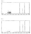
- FIG. 2 shows the results of its 1 H-NMR measurement (measurement solvent: THF-d8).
- FIG. 3 shows the results of its 1 H-NMR measurement (measurement solvent: THF-d8).
- the APCI-TOFMS of the compound showed an [M+H] + peak at an m/z of 1037.
- the APCI-TOFMS of the compound showed an [M+H] + peak at an m/z of 801.
- the APCI-TOFMS of the compound showed an [M+H] + peak at an m/z of 855.
- the APCI-TOFMS of the compound showed an [M+H] + peak at an m/z of 877.
- the APCI-TOFMS of the compound showed an [M+H] + peak at an m/z of 853.
- the APCI-TOFMS of the compound showed an [M+H] + peak at an m/z of 811.
- Each thin film was laminated by a vacuum deposition method at a degree of vacuum of 4.0 ⁇ 10 -5 Pa on a glass substrate on which an anode formed of ITO having a thickness of 110 nm had been formed.
- copper phthalocyanine (CuPC) was formed on ITO so as to have a thickness of 25 nm.
- NPB 4,4'-bis[N-(1-naphthyl)-N-phenylamino]biphenyl
- the compound (1-4) as a host material and tris(2-phenylpyridine)iridium(III) (Ir(ppy) 3 ) as a phosphorescent light-emitting dopant were co-deposited from different deposition sources onto the hole-transporting layer to form a light-emitting layer having a thickness of 40 nm.
- the concentration of Ir(ppy) 3 in the light-emitting layer was 10.0 wt%.
- tris(8-hydroxyquinolinato)aluminum(III) (Alq3) was formed thereon so as to serve as an electron-transporting layer having a thickness of 20 nm.
- lithium fluoride (LiF) was formed on the electron-transporting layer so as to serve as an electron-injecting layer having a thickness of 1.0 nm.
- aluminum (Al) was formed on the electron-injecting layer so as to serve as an electrode having a thickness of 70 nm.
- Organic EL devices were each produced in the same manner as in Example 9 except that the compound (3-3), (1-25), (2-15), (1-19), (3-11), (1-8), or (2-19) was used instead of the compound (1-4) as the host material for the light-emitting layer in Example 9. It was found that the local maximum wavelength of the emission spectrum of each of the devices was 530 nm and hence light emission from Ir(ppy) 3 was obtained. Table 1 shows the respective light-emitting characteristics.
- An organic EL device was produced in the same manner as in Example 9 except that CBP was used as the host material for the light-emitting layer in Example 9. It was identified that the local maximum wavelength of the emission spectrum of the device was 535 nm and hence light emission from Ir(ppy) 3 was obtained. Table 1 shows light-emitting characteristics.
- a balance among various energy values for the ionization potential, electron affinity, and triplet excitation energy of the silicon-containing four-membered ring compound to be used in the organic electroluminescent device of the present invention may be improved by introducing an aromatic heterocyclic group to its skeleton.
- the compound may be allowed to have a high charge-resisting characteristic and a good charge balance by separating its HOMO and LUMO as molecular orbitals responsible for hole- and electron-transferring abilities.
Applications Claiming Priority (2)
| Application Number | Priority Date | Filing Date | Title |
|---|---|---|---|
| JP2011198703 | 2011-09-12 | ||
| PCT/JP2012/072272 WO2013038929A1 (fr) | 2011-09-12 | 2012-08-31 | Matériau pour élément électroluminescent organique ayant une structure de cycle à quatre chaînons contenant du silicium, et élément électroluminescent organique l'utilisant |
Publications (1)
| Publication Number | Publication Date |
|---|---|
| EP2762483A1 true EP2762483A1 (fr) | 2014-08-06 |
Family
ID=47883161
Family Applications (1)
| Application Number | Title | Priority Date | Filing Date |
|---|---|---|---|
| EP12831426.7A Withdrawn EP2762483A1 (fr) | 2011-09-12 | 2012-08-31 | Matériau pour élément électroluminescent organique ayant une structure de cycle à quatre chaînons contenant du silicium, et élément électroluminescent organique l'utilisant |
Country Status (7)
| Country | Link |
|---|---|
| US (1) | US20140203270A1 (fr) |
| EP (1) | EP2762483A1 (fr) |
| JP (1) | JPWO2013038929A1 (fr) |
| KR (1) | KR20140076572A (fr) |
| CN (1) | CN103814035A (fr) |
| TW (1) | TW201326189A (fr) |
| WO (1) | WO2013038929A1 (fr) |
Cited By (3)
| Publication number | Priority date | Publication date | Assignee | Title |
|---|---|---|---|---|
| JP2013538949A (ja) * | 2010-10-01 | 2013-10-17 | バノム インコーポレイテッド | 耐切断性衣服 |
| WO2020144094A1 (fr) * | 2019-01-08 | 2020-07-16 | Basf Se | Procédé de préparation d'absorbeurs uv |
| WO2020144093A1 (fr) | 2019-01-08 | 2020-07-16 | Basf Se | Procédé de préparation d'intermédiaires de triazine et procédé de préparation d'absorbeurs uv associés |
Families Citing this family (1)
| Publication number | Priority date | Publication date | Assignee | Title |
|---|---|---|---|---|
| JP6144161B2 (ja) * | 2013-09-03 | 2017-06-07 | 株式会社日本触媒 | 窒化ケイ素膜原料、およびこの原料から得られた窒化ケイ素膜 |
Family Cites Families (95)
| Publication number | Priority date | Publication date | Assignee | Title |
|---|---|---|---|---|
| US3140288A (en) * | 1962-02-02 | 1964-07-07 | Minnesota Mining & Mfg | Cyclodisilazane compounds |
| JPS63190343A (ja) * | 1987-02-03 | 1988-08-05 | Fujitsu Ltd | 半導体装置の絶縁膜形成方法 |
| US4950950A (en) | 1989-05-18 | 1990-08-21 | Eastman Kodak Company | Electroluminescent device with silazane-containing luminescent zone |
| JP4357781B2 (ja) | 1999-12-01 | 2009-11-04 | ザ、トラスティーズ オブ プリンストン ユニバーシティ | 有機led用燐光性ドーパントとしての式l2mxの錯体 |
| JP2001313178A (ja) | 2000-04-28 | 2001-11-09 | Pioneer Electronic Corp | 有機エレクトロルミネッセンス素子 |
| JP4340401B2 (ja) | 2000-07-17 | 2009-10-07 | 富士フイルム株式会社 | 発光素子及びイリジウム錯体 |
| US6939624B2 (en) | 2000-08-11 | 2005-09-06 | Universal Display Corporation | Organometallic compounds and emission-shifting organic electrophosphorescence |
| CN101924190B (zh) | 2000-08-11 | 2012-07-04 | 普林斯顿大学理事会 | 有机金属化合物和发射转换有机电致磷光 |
| JP3812730B2 (ja) | 2001-02-01 | 2006-08-23 | 富士写真フイルム株式会社 | 遷移金属錯体及び発光素子 |
| JP4285947B2 (ja) | 2001-06-15 | 2009-06-24 | 三洋電機株式会社 | 発光性有機金属化合物及び発光素子 |
| JP2003123982A (ja) | 2001-08-07 | 2003-04-25 | Fuji Photo Film Co Ltd | 発光素子及び新規イリジウム錯体 |
| JP2003073387A (ja) | 2001-09-04 | 2003-03-12 | Canon Inc | 金属配位化合物及び有機発光素子 |
| JP2003253145A (ja) | 2002-02-28 | 2003-09-10 | Jsr Corp | 発光性組成物 |
| JP2003253128A (ja) | 2002-02-28 | 2003-09-10 | Jsr Corp | 発光性組成物 |
| JP2003253129A (ja) | 2002-02-28 | 2003-09-10 | Jsr Corp | 発光性組成物 |
| JP3969132B2 (ja) | 2002-03-12 | 2007-09-05 | コニカミノルタホールディングス株式会社 | 有機エレクトロルミネッセンス素子及びそれを用いた表示装置 |
| US6916554B2 (en) | 2002-11-06 | 2005-07-12 | The University Of Southern California | Organic light emitting materials and devices |
| KR20050052473A (ko) | 2002-08-16 | 2005-06-02 | 더 유니버시티 오브 써던 캘리포니아 | 유기 발광 물질 및 장치 |
| JP2004111193A (ja) | 2002-09-18 | 2004-04-08 | Konica Minolta Holdings Inc | 有機エレクトロルミネッセンス素子及び表示装置 |
| US20040086743A1 (en) | 2002-11-06 | 2004-05-06 | Brown Cory S. | Organometallic compounds for use in electroluminescent devices |
| JP4218311B2 (ja) | 2002-11-06 | 2009-02-04 | 株式会社豊田中央研究所 | 有機金属錯体化合物及びこれを用いた有機発光素子 |
| US6858327B2 (en) | 2002-11-08 | 2005-02-22 | Universal Display Corporation | Organic light emitting materials and devices |
| US7531679B2 (en) * | 2002-11-14 | 2009-05-12 | Advanced Technology Materials, Inc. | Composition and method for low temperature deposition of silicon-containing films such as films including silicon nitride, silicon dioxide and/or silicon-oxynitride |
| US7446217B2 (en) * | 2002-11-14 | 2008-11-04 | Advanced Technology Materials, Inc. | Composition and method for low temperature deposition of silicon-containing films |
| JP2004319438A (ja) | 2003-03-28 | 2004-11-11 | Konica Minolta Holdings Inc | 有機エレクトロルミネッセンス素子、表示装置、照明装置及びロジウム錯体化合物 |
| KR100682858B1 (ko) | 2003-06-26 | 2007-02-15 | 삼성에스디아이 주식회사 | 유기 금속 착물 및 이를 채용한 유기 전계 발광 소자 |
| KR100718100B1 (ko) | 2003-09-06 | 2007-05-14 | 삼성에스디아이 주식회사 | 이핵 유기금속 착물 및 이를 이용한 유기 전계 발광 소자 |
| KR100773523B1 (ko) | 2003-11-06 | 2007-11-07 | 삼성에스디아이 주식회사 | 유기 금속 착물 및 이를 이용한 유기 전계 발광 소자 |
| KR100773524B1 (ko) | 2003-12-24 | 2007-11-07 | 삼성에스디아이 주식회사 | 이핵 유기 금속 착물 및 이를 이용한 유기 전계 발광 소자 |
| US7279232B2 (en) | 2004-01-26 | 2007-10-09 | Universal Display Corporation | Electroluminescent stability |
| KR100537621B1 (ko) | 2004-02-02 | 2005-12-19 | 삼성에스디아이 주식회사 | 이리듐 화합물 및 이를 이용한 유기 전계 발광 소자 |
| US7332232B2 (en) | 2004-02-03 | 2008-02-19 | Universal Display Corporation | OLEDs utilizing multidentate ligand systems |
| WO2005113704A2 (fr) | 2004-05-18 | 2005-12-01 | The University Of Southern California | Composes luminescents a ligands carbene |
| US7534505B2 (en) | 2004-05-18 | 2009-05-19 | The University Of Southern California | Organometallic compounds for use in electroluminescent devices |
| US7279704B2 (en) | 2004-05-18 | 2007-10-09 | The University Of Southern California | Complexes with tridentate ligands |
| WO2006004164A1 (fr) | 2004-07-06 | 2006-01-12 | Canon Kabushiki Kaisha | Procédé de fabrication de motif d’activation |
| US20060008670A1 (en) | 2004-07-06 | 2006-01-12 | Chun Lin | Organic light emitting materials and devices |
| EP1763902B1 (fr) | 2004-07-07 | 2018-08-29 | Universal Display Corporation | Materiaux electroluminescents stables et efficaces |
| KR101030011B1 (ko) | 2004-08-28 | 2011-04-20 | 삼성모바일디스플레이주식회사 | 시클로메탈화 전이금속 착물 및 이를 이용한 유기 전계발광 소자 |
| JP4500735B2 (ja) | 2004-09-22 | 2010-07-14 | 富士フイルム株式会社 | 有機電界発光素子 |
| JP4531509B2 (ja) | 2004-09-27 | 2010-08-25 | 富士フイルム株式会社 | 発光素子 |
| KR100668305B1 (ko) | 2004-10-01 | 2007-01-12 | 삼성에스디아이 주식회사 | 시클로메탈화 전이금속 착물 및 이를 이용한 유기 전계발광 소자 |
| JP4687059B2 (ja) | 2004-10-06 | 2011-05-25 | 凸版印刷株式会社 | 有機金属錯体、および発光材料、並びに発光素子 |
| KR101015882B1 (ko) | 2004-10-11 | 2011-02-23 | 삼성모바일디스플레이주식회사 | 시클로메탈화 전이금속 착물 및 이를 이용한 유기 전계발광 소자 |
| JP5243684B2 (ja) | 2004-11-04 | 2013-07-24 | ユー・ディー・シー アイルランド リミテッド | 有機金属錯体、発光性固体、有機el素子及び有機elディスプレイ |
| JP4362461B2 (ja) * | 2004-11-05 | 2009-11-11 | 三星モバイルディスプレイ株式會社 | 有機電界発光素子 |
| JP2006131561A (ja) | 2004-11-08 | 2006-05-25 | Idemitsu Kosan Co Ltd | 金属錯体化合物 |
| KR101234226B1 (ko) | 2005-02-03 | 2013-02-18 | 삼성디스플레이 주식회사 | 유기 금속 착물 및 이를 이용한 유기 전계 발광 소자 |
| WO2006100888A1 (fr) | 2005-03-22 | 2006-09-28 | Konica Minolta Holdings, Inc. | Materiau pour dispositif el organique, dispositif el organique, dispositif d’affichage et d’eclairage |
| KR101223717B1 (ko) | 2005-04-12 | 2013-01-18 | 삼성디스플레이 주식회사 | 실릴 치환된 시클로메탈화 전이금속 착물 및 이를 이용한 유기 전계 발광 소자 |
| KR100732823B1 (ko) | 2005-04-21 | 2007-06-27 | 삼성에스디아이 주식회사 | 호스트용 화합물과 도판트용 화합물이 연결된 유기 금속화합물, 이를 이용한 유기 전계 발광 소자 및 그의제조방법 |
| KR100611885B1 (ko) | 2005-04-21 | 2006-08-11 | 삼성에스디아이 주식회사 | 호스트용 화합물과 도판트용 화합물이 연결된 유기 금속화합물, 이를 이용한 유기 전계 발광 소자 및 그의제조방법 |
| JP2006303394A (ja) | 2005-04-25 | 2006-11-02 | Fuji Photo Film Co Ltd | 有機電界発光素子 |
| JP4801928B2 (ja) | 2005-04-25 | 2011-10-26 | 富士フイルム株式会社 | 有機電界発光素子 |
| JP2006310479A (ja) | 2005-04-27 | 2006-11-09 | Fuji Photo Film Co Ltd | 有機電界発光素子 |
| US7902374B2 (en) | 2005-05-06 | 2011-03-08 | Universal Display Corporation | Stability OLED materials and devices |
| US9051344B2 (en) | 2005-05-06 | 2015-06-09 | Universal Display Corporation | Stability OLED materials and devices |
| JP4904727B2 (ja) | 2005-06-23 | 2012-03-28 | コニカミノルタホールディングス株式会社 | 有機エレクトロルミネッセンス素子材料、有機エレクトロルミネッセンス素子、表示装置及び照明装置 |
| JP4935001B2 (ja) | 2005-06-29 | 2012-05-23 | コニカミノルタホールディングス株式会社 | 有機エレクトロルミネッセンス素子材料 |
| JP5076891B2 (ja) | 2005-07-01 | 2012-11-21 | コニカミノルタホールディングス株式会社 | 有機エレクトロルミネッセンス素子材料、有機エレクトロルミネッセンス素子、表示装置及び照明装置 |
| KR20080037006A (ko) | 2005-08-05 | 2008-04-29 | 이데미쓰 고산 가부시키가이샤 | 전이금속 착체화합물 및 그것을 이용한 유기 전기발광 소자 |
| JP5130913B2 (ja) | 2005-08-25 | 2013-01-30 | コニカミノルタホールディングス株式会社 | 有機エレクトロルミネッセンス素子材料、有機エレクトロルミネッセンス素子、表示装置及び照明装置 |
| JP2007088105A (ja) | 2005-09-20 | 2007-04-05 | Fujifilm Corp | 有機電界発光素子 |
| JPWO2007058080A1 (ja) | 2005-11-17 | 2009-04-30 | 出光興産株式会社 | 金属錯体化合物及びそれを用いた有機エレクトロルミネッセンス素子 |
| JPWO2007058104A1 (ja) | 2005-11-17 | 2009-04-30 | 出光興産株式会社 | 金属錯体化合物及びそれを用いた有機エレクトロルミネッセンス素子 |
| KR102103062B1 (ko) | 2006-02-10 | 2020-04-22 | 유니버셜 디스플레이 코포레이션 | 시클로금속화 이미다조[1,2-f]페난트리딘 및 디이미다조[1,2-a:1',2'-c]퀴나졸린 리간드, 및 이의 등전자성 및 벤즈고리화된 유사체의 금속 착체 |
| JP4945156B2 (ja) | 2006-03-24 | 2012-06-06 | 富士フイルム株式会社 | 有機電界発光素子 |
| EP1842854A1 (fr) | 2006-04-07 | 2007-10-10 | SOLVAY (Société Anonyme) | Matériau électroluminescent |
| US7737277B2 (en) | 2006-05-08 | 2010-06-15 | E.I. Du Pont De Nemours And Company | Electroluminescent bis-cyclometalled iridium compounds and devices made with such compounds |
| JP5144034B2 (ja) | 2006-05-31 | 2013-02-13 | 富士フイルム株式会社 | 有機電界発光素子 |
| JP5127828B2 (ja) | 2006-06-26 | 2013-01-23 | ビーエーエスエフ ソシエタス・ヨーロピア | 架橋カルベン配位子を有するPtとPdのビスカルベン錯体及びテトラカルベン錯体のOLED内での利用 |
| JP2008037848A (ja) | 2006-08-10 | 2008-02-21 | Takasago Internatl Corp | 白金錯体及び発光素子 |
| JP5644050B2 (ja) | 2006-09-20 | 2014-12-24 | コニカミノルタ株式会社 | 有機エレクトロルミネッセンス素子材料 |
| KR101426109B1 (ko) | 2006-10-24 | 2014-08-05 | 우베 고산 가부시키가이샤 | 금 착체 및 그의 제조 방법, 및 상기 금 착체를 이용하는 유기 자외 전계 발광 소자 |
| JP5127206B2 (ja) | 2006-11-28 | 2013-01-23 | キヤノン株式会社 | 金属錯体化合物、有機発光素子及び表示装置 |
| US8778508B2 (en) | 2006-12-08 | 2014-07-15 | Universal Display Corporation | Light-emitting organometallic complexes |
| KR101634508B1 (ko) | 2007-03-08 | 2016-06-28 | 유니버셜 디스플레이 코포레이션 | 인광성 물질 |
| JP2008270737A (ja) | 2007-03-23 | 2008-11-06 | Fujifilm Corp | 有機電界発光素子 |
| JP2008239565A (ja) | 2007-03-28 | 2008-10-09 | Idemitsu Kosan Co Ltd | イリジウム錯体とその製造法及びそれを用いた有機エレクトロルミネッセンス |
| JP5202864B2 (ja) | 2007-03-29 | 2013-06-05 | コニカミノルタホールディングス株式会社 | 有機エレクトロルミネッセンス素子及びそれを用いた表示装置 |
| JP2008266163A (ja) | 2007-04-17 | 2008-11-06 | Idemitsu Kosan Co Ltd | 遷移金属錯体化合物及びそれを用いた有機エレクトロルミネッセンス素子 |
| US7993763B2 (en) | 2007-05-10 | 2011-08-09 | Universal Display Corporation | Organometallic compounds having host and dopant functionalities |
| JP5256485B2 (ja) | 2007-05-16 | 2013-08-07 | コニカミノルタ株式会社 | 有機エレクトロルミネッセンス素子、表示装置及び照明装置 |
| WO2008156879A1 (fr) | 2007-06-20 | 2008-12-24 | Universal Display Corporation | Matériaux à base d'imidazophénantridine phosphorescente bleue |
| JP5088025B2 (ja) | 2007-07-12 | 2012-12-05 | コニカミノルタホールディングス株式会社 | 有機エレクトロルミネッセンス材料、有機エレクトロルミネッセンス素子、表示装置及び照明装置 |
| JP2009057367A (ja) | 2007-08-03 | 2009-03-19 | Idemitsu Kosan Co Ltd | 金属錯体化合物、有機エレクトロルミネッセンス素子用材料及びそれを用いた有機エレクトロルミネッセンス素子 |
| JP5115094B2 (ja) | 2007-08-21 | 2013-01-09 | コニカミノルタホールディングス株式会社 | 有機エレクトロルミネッセンス素子材料、有機エレクトロルミネッセンス素子、表示装置及び照明装置 |
| JP2009057304A (ja) | 2007-08-30 | 2009-03-19 | Mitsubishi Chemicals Corp | 金属錯体及び有機電界発光素子 |
| JP5438941B2 (ja) | 2007-09-25 | 2014-03-12 | ユー・ディー・シー アイルランド リミテッド | 有機電界発光素子 |
| JP4816610B2 (ja) | 2007-09-26 | 2011-11-16 | コニカミノルタホールディングス株式会社 | 有機エレクトロルミネッセンス素子 |
| US8067100B2 (en) | 2007-10-04 | 2011-11-29 | Universal Display Corporation | Complexes with tridentate ligands |
| JP2009114369A (ja) | 2007-11-08 | 2009-05-28 | Konica Minolta Holdings Inc | 有機エレクトロルミネッセンス材料、有機エレクトロルミネッセンス素子、表示装置及び照明装置 |
| JP5438955B2 (ja) | 2007-12-14 | 2014-03-12 | ユー・ディー・シー アイルランド リミテッド | 白金錯体化合物及びこれを用いた有機電界発光素子 |
| JP2009286716A (ja) | 2008-05-28 | 2009-12-10 | Sumitomo Seika Chem Co Ltd | イリジウム錯体 |
| JP2010083852A (ja) | 2008-10-03 | 2010-04-15 | Wakayama Univ | 金属錯体の製造方法、金属錯体および有機電界発光素子 |
-
2012
- 2012-08-31 KR KR1020147009387A patent/KR20140076572A/ko not_active Application Discontinuation
- 2012-08-31 US US14/240,608 patent/US20140203270A1/en not_active Abandoned
- 2012-08-31 EP EP12831426.7A patent/EP2762483A1/fr not_active Withdrawn
- 2012-08-31 CN CN201280044043.9A patent/CN103814035A/zh active Pending
- 2012-08-31 JP JP2013533609A patent/JPWO2013038929A1/ja active Pending
- 2012-08-31 WO PCT/JP2012/072272 patent/WO2013038929A1/fr active Application Filing
- 2012-09-11 TW TW101133128A patent/TW201326189A/zh unknown
Non-Patent Citations (1)
| Title |
|---|
| See references of WO2013038929A1 * |
Cited By (3)
| Publication number | Priority date | Publication date | Assignee | Title |
|---|---|---|---|---|
| JP2013538949A (ja) * | 2010-10-01 | 2013-10-17 | バノム インコーポレイテッド | 耐切断性衣服 |
| WO2020144094A1 (fr) * | 2019-01-08 | 2020-07-16 | Basf Se | Procédé de préparation d'absorbeurs uv |
| WO2020144093A1 (fr) | 2019-01-08 | 2020-07-16 | Basf Se | Procédé de préparation d'intermédiaires de triazine et procédé de préparation d'absorbeurs uv associés |
Also Published As
| Publication number | Publication date |
|---|---|
| KR20140076572A (ko) | 2014-06-20 |
| TW201326189A (zh) | 2013-07-01 |
| CN103814035A (zh) | 2014-05-21 |
| US20140203270A1 (en) | 2014-07-24 |
| WO2013038929A1 (fr) | 2013-03-21 |
| JPWO2013038929A1 (ja) | 2015-03-26 |
Similar Documents
| Publication | Publication Date | Title |
|---|---|---|
| EP2869356B1 (fr) | Élément à électroluminescence organique et matériau pour un élément à électroluminescence organique | |
| EP2618394B1 (fr) | Élément électroluminescent organique | |
| EP2535958B1 (fr) | Élément électroluminescent organique | |
| EP2985802B1 (fr) | Composé adamantane pour éléments électroluminescents organiques, et élément électroluminescent organique | |
| EP2827397A1 (fr) | Élément électroluminescent organique | |
| EP2650941A1 (fr) | Élément électroluminescent organique | |
| EP2629345B1 (fr) | Élément électroluminescent organique | |
| EP3054496B1 (fr) | Matériau pour élément électroluminescent organique et élément électroluminescent organique qui l'utilise | |
| EP3125326B1 (fr) | Matériau d'élément électroluminescent organique et éléments électroluminescents organiques utilisant celui-ci | |
| EP3089230B1 (fr) | Matériau pour éléments électroluminescents organiques et élément électroluminescent organique l'utilisant | |
| EP3054495B1 (fr) | Matériau pour des éléments électroluminescents organiques et élément électroluminescent organique utilisant ce dernier | |
| EP2687530B1 (fr) | Composés aromatiques contenant de l'azote et dispositif électroluminescent organique | |
| EP2876699B1 (fr) | Élément électroluminescent organique | |
| US20180114908A1 (en) | Organic-electroluminescent-element material, and organic electroluminescent element using same | |
| EP3125325B1 (fr) | Matériau d'élément électroluminescent organique et élément électroluminescent organique l'utilisant | |
| EP3125324B1 (fr) | Matériau pour élément électroluminescent organique et élément électroluminescent organique utilisant celui-ci | |
| EP3089231B1 (fr) | Matériau pour éléments organiques électroluminescents et élément organique électroluminescent l'utilisant | |
| EP2762483A1 (fr) | Matériau pour élément électroluminescent organique ayant une structure de cycle à quatre chaînons contenant du silicium, et élément électroluminescent organique l'utilisant | |
| EP3279962B1 (fr) | Matériau pour élément électroluminescent organique et élément électroluminescent organique l'utilisant |
Legal Events
| Date | Code | Title | Description |
|---|---|---|---|
| PUAI | Public reference made under article 153(3) epc to a published international application that has entered the european phase |
Free format text: ORIGINAL CODE: 0009012 |
|
| 17P | Request for examination filed |
Effective date: 20140328 |
|
| AK | Designated contracting states |
Kind code of ref document: A1 Designated state(s): AL AT BE BG CH CY CZ DE DK EE ES FI FR GB GR HR HU IE IS IT LI LT LU LV MC MK MT NL NO PL PT RO RS SE SI SK SM TR |
|
| DAX | Request for extension of the european patent (deleted) | ||
| STAA | Information on the status of an ep patent application or granted ep patent |
Free format text: STATUS: THE APPLICATION HAS BEEN WITHDRAWN |
|
| 18W | Application withdrawn |
Effective date: 20150427 |