EP2755818B1 - Elastischer bodenbelag - Google Patents
Elastischer bodenbelag Download PDFInfo
- Publication number
- EP2755818B1 EP2755818B1 EP20110788034 EP11788034A EP2755818B1 EP 2755818 B1 EP2755818 B1 EP 2755818B1 EP 20110788034 EP20110788034 EP 20110788034 EP 11788034 A EP11788034 A EP 11788034A EP 2755818 B1 EP2755818 B1 EP 2755818B1
- Authority
- EP
- European Patent Office
- Prior art keywords
- layer
- core
- floor covering
- polyurethane
- floor
- Prior art date
- Legal status (The legal status is an assumption and is not a legal conclusion. Google has not performed a legal analysis and makes no representation as to the accuracy of the status listed.)
- Active
Links
- 229920002635 polyurethane Polymers 0.000 claims description 37
- 239000004814 polyurethane Substances 0.000 claims description 37
- 238000000034 method Methods 0.000 claims description 32
- 229920005862 polyol Polymers 0.000 claims description 30
- -1 aliphatic polyol Chemical class 0.000 claims description 19
- 239000003365 glass fiber Substances 0.000 claims description 19
- 239000002131 composite material Substances 0.000 claims description 17
- 239000000463 material Substances 0.000 claims description 15
- 150000003077 polyols Chemical class 0.000 claims description 11
- 230000000035 biogenic effect Effects 0.000 claims description 9
- 239000002994 raw material Substances 0.000 claims description 7
- 239000001913 cellulose Substances 0.000 claims description 6
- 229920002678 cellulose Polymers 0.000 claims description 6
- 239000000853 adhesive Substances 0.000 claims description 4
- 230000001070 adhesive effect Effects 0.000 claims description 4
- 239000012939 laminating adhesive Substances 0.000 claims description 4
- 238000005304 joining Methods 0.000 claims description 3
- 238000004519 manufacturing process Methods 0.000 claims description 3
- 235000019482 Palm oil Nutrition 0.000 claims description 2
- 235000019484 Rapeseed oil Nutrition 0.000 claims description 2
- 235000019438 castor oil Nutrition 0.000 claims description 2
- 239000004359 castor oil Substances 0.000 claims description 2
- 239000006185 dispersion Substances 0.000 claims description 2
- 238000009472 formulation Methods 0.000 claims description 2
- ZEMPKEQAKRGZGQ-XOQCFJPHSA-N glycerol triricinoleate Natural products CCCCCC[C@@H](O)CC=CCCCCCCCC(=O)OC[C@@H](COC(=O)CCCCCCCC=CC[C@@H](O)CCCCCC)OC(=O)CCCCCCCC=CC[C@H](O)CCCCCC ZEMPKEQAKRGZGQ-XOQCFJPHSA-N 0.000 claims description 2
- 239000000203 mixture Substances 0.000 claims description 2
- 239000002540 palm oil Substances 0.000 claims description 2
- 235000015112 vegetable and seed oil Nutrition 0.000 claims description 2
- 239000008158 vegetable oil Substances 0.000 claims description 2
- PXFBZOLANLWPMH-UHFFFAOYSA-N 16-Epiaffinine Natural products C1C(C2=CC=CC=C2N2)=C2C(=O)CC2C(=CC)CN(C)C1C2CO PXFBZOLANLWPMH-UHFFFAOYSA-N 0.000 claims 1
- 238000009408 flooring Methods 0.000 description 16
- 230000007613 environmental effect Effects 0.000 description 7
- 238000010030 laminating Methods 0.000 description 4
- 239000000758 substrate Substances 0.000 description 4
- 239000002341 toxic gas Substances 0.000 description 4
- 230000015572 biosynthetic process Effects 0.000 description 2
- 238000004140 cleaning Methods 0.000 description 2
- 239000011248 coating agent Substances 0.000 description 2
- 238000000576 coating method Methods 0.000 description 2
- 238000009434 installation Methods 0.000 description 2
- 229920003023 plastic Polymers 0.000 description 2
- 239000004033 plastic Substances 0.000 description 2
- 238000005496 tempering Methods 0.000 description 2
- 239000002023 wood Substances 0.000 description 2
- 238000004026 adhesive bonding Methods 0.000 description 1
- 238000001816 cooling Methods 0.000 description 1
- 230000032798 delamination Effects 0.000 description 1
- 230000000694 effects Effects 0.000 description 1
- 229920001971 elastomer Polymers 0.000 description 1
- 239000011152 fibreglass Substances 0.000 description 1
- 239000000945 filler Substances 0.000 description 1
- 238000010438 heat treatment Methods 0.000 description 1
- 238000009413 insulation Methods 0.000 description 1
- 230000008092 positive effect Effects 0.000 description 1
- 238000002360 preparation method Methods 0.000 description 1
- 238000011084 recovery Methods 0.000 description 1
- 230000000717 retained effect Effects 0.000 description 1
- 238000013517 stratification Methods 0.000 description 1
- 238000003786 synthesis reaction Methods 0.000 description 1
- 229920001169 thermoplastic Polymers 0.000 description 1
- 239000004416 thermosoftening plastic Substances 0.000 description 1
Images

Classifications
-
- E—FIXED CONSTRUCTIONS
- E04—BUILDING
- E04F—FINISHING WORK ON BUILDINGS, e.g. STAIRS, FLOORS
- E04F15/00—Flooring
- E04F15/02—Flooring or floor layers composed of a number of similar elements
- E04F15/10—Flooring or floor layers composed of a number of similar elements of other materials, e.g. fibrous or chipped materials, organic plastics, magnesite tiles, hardboard, or with a top layer of other materials
- E04F15/105—Flooring or floor layers composed of a number of similar elements of other materials, e.g. fibrous or chipped materials, organic plastics, magnesite tiles, hardboard, or with a top layer of other materials of organic plastics with or without reinforcements or filling materials
-
- B—PERFORMING OPERATIONS; TRANSPORTING
- B32—LAYERED PRODUCTS
- B32B—LAYERED PRODUCTS, i.e. PRODUCTS BUILT-UP OF STRATA OF FLAT OR NON-FLAT, e.g. CELLULAR OR HONEYCOMB, FORM
- B32B27/00—Layered products comprising a layer of synthetic resin
- B32B27/06—Layered products comprising a layer of synthetic resin as the main or only constituent of a layer, which is next to another layer of the same or of a different material
- B32B27/08—Layered products comprising a layer of synthetic resin as the main or only constituent of a layer, which is next to another layer of the same or of a different material of synthetic resin
-
- B—PERFORMING OPERATIONS; TRANSPORTING
- B32—LAYERED PRODUCTS
- B32B—LAYERED PRODUCTS, i.e. PRODUCTS BUILT-UP OF STRATA OF FLAT OR NON-FLAT, e.g. CELLULAR OR HONEYCOMB, FORM
- B32B27/00—Layered products comprising a layer of synthetic resin
- B32B27/06—Layered products comprising a layer of synthetic resin as the main or only constituent of a layer, which is next to another layer of the same or of a different material
- B32B27/10—Layered products comprising a layer of synthetic resin as the main or only constituent of a layer, which is next to another layer of the same or of a different material of paper or cardboard
-
- B—PERFORMING OPERATIONS; TRANSPORTING
- B32—LAYERED PRODUCTS
- B32B—LAYERED PRODUCTS, i.e. PRODUCTS BUILT-UP OF STRATA OF FLAT OR NON-FLAT, e.g. CELLULAR OR HONEYCOMB, FORM
- B32B27/00—Layered products comprising a layer of synthetic resin
- B32B27/12—Layered products comprising a layer of synthetic resin next to a fibrous or filamentary layer
-
- B—PERFORMING OPERATIONS; TRANSPORTING
- B32—LAYERED PRODUCTS
- B32B—LAYERED PRODUCTS, i.e. PRODUCTS BUILT-UP OF STRATA OF FLAT OR NON-FLAT, e.g. CELLULAR OR HONEYCOMB, FORM
- B32B27/00—Layered products comprising a layer of synthetic resin
- B32B27/40—Layered products comprising a layer of synthetic resin comprising polyurethanes
-
- B—PERFORMING OPERATIONS; TRANSPORTING
- B32—LAYERED PRODUCTS
- B32B—LAYERED PRODUCTS, i.e. PRODUCTS BUILT-UP OF STRATA OF FLAT OR NON-FLAT, e.g. CELLULAR OR HONEYCOMB, FORM
- B32B29/00—Layered products comprising a layer of paper or cardboard
- B32B29/02—Layered products comprising a layer of paper or cardboard next to a fibrous or filamentary layer
-
- B—PERFORMING OPERATIONS; TRANSPORTING
- B32—LAYERED PRODUCTS
- B32B—LAYERED PRODUCTS, i.e. PRODUCTS BUILT-UP OF STRATA OF FLAT OR NON-FLAT, e.g. CELLULAR OR HONEYCOMB, FORM
- B32B3/00—Layered products comprising a layer with external or internal discontinuities or unevennesses, or a layer of non-planar form; Layered products having particular features of form
- B32B3/02—Layered products comprising a layer with external or internal discontinuities or unevennesses, or a layer of non-planar form; Layered products having particular features of form characterised by features of form at particular places, e.g. in edge regions
- B32B3/06—Layered products comprising a layer with external or internal discontinuities or unevennesses, or a layer of non-planar form; Layered products having particular features of form characterised by features of form at particular places, e.g. in edge regions for securing layers together; for attaching the product to another member, e.g. to a support, or to another product, e.g. groove/tongue, interlocking
-
- B—PERFORMING OPERATIONS; TRANSPORTING
- B32—LAYERED PRODUCTS
- B32B—LAYERED PRODUCTS, i.e. PRODUCTS BUILT-UP OF STRATA OF FLAT OR NON-FLAT, e.g. CELLULAR OR HONEYCOMB, FORM
- B32B38/00—Ancillary operations in connection with laminating processes
-
- B—PERFORMING OPERATIONS; TRANSPORTING
- B32—LAYERED PRODUCTS
- B32B—LAYERED PRODUCTS, i.e. PRODUCTS BUILT-UP OF STRATA OF FLAT OR NON-FLAT, e.g. CELLULAR OR HONEYCOMB, FORM
- B32B38/00—Ancillary operations in connection with laminating processes
- B32B38/10—Removing layers, or parts of layers, mechanically or chemically
-
- E—FIXED CONSTRUCTIONS
- E04—BUILDING
- E04F—FINISHING WORK ON BUILDINGS, e.g. STAIRS, FLOORS
- E04F15/00—Flooring
- E04F15/02—Flooring or floor layers composed of a number of similar elements
- E04F15/10—Flooring or floor layers composed of a number of similar elements of other materials, e.g. fibrous or chipped materials, organic plastics, magnesite tiles, hardboard, or with a top layer of other materials
- E04F15/107—Flooring or floor layers composed of a number of similar elements of other materials, e.g. fibrous or chipped materials, organic plastics, magnesite tiles, hardboard, or with a top layer of other materials composed of several layers, e.g. sandwich panels
-
- B—PERFORMING OPERATIONS; TRANSPORTING
- B32—LAYERED PRODUCTS
- B32B—LAYERED PRODUCTS, i.e. PRODUCTS BUILT-UP OF STRATA OF FLAT OR NON-FLAT, e.g. CELLULAR OR HONEYCOMB, FORM
- B32B2260/00—Layered product comprising an impregnated, embedded, or bonded layer wherein the layer comprises an impregnation, embedding, or binder material
- B32B2260/02—Composition of the impregnated, bonded or embedded layer
- B32B2260/028—Paper layer
-
- B—PERFORMING OPERATIONS; TRANSPORTING
- B32—LAYERED PRODUCTS
- B32B—LAYERED PRODUCTS, i.e. PRODUCTS BUILT-UP OF STRATA OF FLAT OR NON-FLAT, e.g. CELLULAR OR HONEYCOMB, FORM
- B32B2260/00—Layered product comprising an impregnated, embedded, or bonded layer wherein the layer comprises an impregnation, embedding, or binder material
- B32B2260/04—Impregnation, embedding, or binder material
- B32B2260/046—Synthetic resin
-
- B—PERFORMING OPERATIONS; TRANSPORTING
- B32—LAYERED PRODUCTS
- B32B—LAYERED PRODUCTS, i.e. PRODUCTS BUILT-UP OF STRATA OF FLAT OR NON-FLAT, e.g. CELLULAR OR HONEYCOMB, FORM
- B32B2262/00—Composition or structural features of fibres which form a fibrous or filamentary layer or are present as additives
- B32B2262/10—Inorganic fibres
- B32B2262/101—Glass fibres
-
- B—PERFORMING OPERATIONS; TRANSPORTING
- B32—LAYERED PRODUCTS
- B32B—LAYERED PRODUCTS, i.e. PRODUCTS BUILT-UP OF STRATA OF FLAT OR NON-FLAT, e.g. CELLULAR OR HONEYCOMB, FORM
- B32B2471/00—Floor coverings
-
- Y—GENERAL TAGGING OF NEW TECHNOLOGICAL DEVELOPMENTS; GENERAL TAGGING OF CROSS-SECTIONAL TECHNOLOGIES SPANNING OVER SEVERAL SECTIONS OF THE IPC; TECHNICAL SUBJECTS COVERED BY FORMER USPC CROSS-REFERENCE ART COLLECTIONS [XRACs] AND DIGESTS
- Y10—TECHNICAL SUBJECTS COVERED BY FORMER USPC
- Y10T—TECHNICAL SUBJECTS COVERED BY FORMER US CLASSIFICATION
- Y10T428/00—Stock material or miscellaneous articles
- Y10T428/24—Structurally defined web or sheet [e.g., overall dimension, etc.]
- Y10T428/24777—Edge feature
- Y10T428/24785—Edge feature including layer embodying mechanically interengaged strands, strand portions or strand-like strips [e.g., weave, knit, etc.]
-
- Y—GENERAL TAGGING OF NEW TECHNOLOGICAL DEVELOPMENTS; GENERAL TAGGING OF CROSS-SECTIONAL TECHNOLOGIES SPANNING OVER SEVERAL SECTIONS OF THE IPC; TECHNICAL SUBJECTS COVERED BY FORMER USPC CROSS-REFERENCE ART COLLECTIONS [XRACs] AND DIGESTS
- Y10—TECHNICAL SUBJECTS COVERED BY FORMER USPC
- Y10T—TECHNICAL SUBJECTS COVERED BY FORMER US CLASSIFICATION
- Y10T428/00—Stock material or miscellaneous articles
- Y10T428/24—Structurally defined web or sheet [e.g., overall dimension, etc.]
- Y10T428/24942—Structurally defined web or sheet [e.g., overall dimension, etc.] including components having same physical characteristic in differing degree
- Y10T428/2495—Thickness [relative or absolute]
- Y10T428/24967—Absolute thicknesses specified
-
- Y—GENERAL TAGGING OF NEW TECHNOLOGICAL DEVELOPMENTS; GENERAL TAGGING OF CROSS-SECTIONAL TECHNOLOGIES SPANNING OVER SEVERAL SECTIONS OF THE IPC; TECHNICAL SUBJECTS COVERED BY FORMER USPC CROSS-REFERENCE ART COLLECTIONS [XRACs] AND DIGESTS
- Y10—TECHNICAL SUBJECTS COVERED BY FORMER USPC
- Y10T—TECHNICAL SUBJECTS COVERED BY FORMER US CLASSIFICATION
- Y10T428/00—Stock material or miscellaneous articles
- Y10T428/249921—Web or sheet containing structurally defined element or component
-
- Y—GENERAL TAGGING OF NEW TECHNOLOGICAL DEVELOPMENTS; GENERAL TAGGING OF CROSS-SECTIONAL TECHNOLOGIES SPANNING OVER SEVERAL SECTIONS OF THE IPC; TECHNICAL SUBJECTS COVERED BY FORMER USPC CROSS-REFERENCE ART COLLECTIONS [XRACs] AND DIGESTS
- Y10—TECHNICAL SUBJECTS COVERED BY FORMER USPC
- Y10T—TECHNICAL SUBJECTS COVERED BY FORMER US CLASSIFICATION
- Y10T428/00—Stock material or miscellaneous articles
- Y10T428/27—Web or sheet containing structurally defined element or component, the element or component having a specified weight per unit area [e.g., gms/sq cm, lbs/sq ft, etc.]
- Y10T428/273—Web or sheet containing structurally defined element or component, the element or component having a specified weight per unit area [e.g., gms/sq cm, lbs/sq ft, etc.] of coating
- Y10T428/277—Cellulosic substrate
Definitions
- the present invention relates to an elastic floor covering, comprising a soft core, a decorative layer arranged on the core, a transparent wear layer lying on the decorative layer and a back layer arranged under the core, wherein at least the core, the wear layer and the back layer consist of polyurethane and between the core and the decorative layer rests a glass fiber mat.
- the flooring of the present type has a layer structure. It has a soft core, a decorative layer disposed on the core, a wear layer lying thereon, and a backing layer located under the core.
- floor coverings in which at least the core, the wear layer and the back layer of polyurethane (PU) are made. This brings various advantages, such as a high dimensional stability, ie there are small changes in the dimensions of the floor covering with temperature fluctuations. Furthermore, such a floor covering has good elastic properties. Deformations, such as those caused by mechanical stresses on the surface, form almost 100%. Of particular importance is also the high environmental impact of such evidence, which must be low in emissions and may not release toxic gases in case of fire.
- the polyol used as a raw material for the synthesis of the polyurethanes used in these floor coverings has hitherto mainly been derived from petrochemical raw materials.
- the higher aliphatic polyol is mainly used for the polyurethane of the wear layer, while the PU material for the core and back layer is usually derived from aromatic polyol.
- the use of aliphatic polyol leads to polyurethanes with high scratch resistance, ease of cleaning, UV stability, impression behavior, resilience and better properties in case of fire.
- the object of the present invention is therefore to further improve a flexible floor covering with the layer structure described above, which consists predominantly or completely of polyurethane, with respect to its properties, in particular with regard to its environmental compatibility and its behavior in case of fire, so that even fewer emissions are released.
- the excellent performance properties of the previously known PU floor coverings are not only intended to be retained, but even improved, in particular with regard to dimensional stability, the impression behavior under load and the restoring behavior.
- the core and backsheet of the flooring of the invention are made of a polyurethane synthesized from an aromatic polyol derived from renewable resources. These are so-called biogenic polyols.
- the polyurethanes produced therefrom have better environmental compatibility properties than polyol of petrochemical origin. In particular, they are very low in emissions and develop no toxic gases even in the event of fire. It is thus possible to use a flexible floor covering almost completely using polyurethane from renewable raw materials and thus to meet the demand for environmentally friendly and sustainable products.
- the polyurethane of the wear layer is made of an aliphatic polyol, while the polyurethane of the core and back layer of biogenic aromatic polyol is synthesized.
- the decorative layer is in the flooring according to the invention of a pulp paper, which is impregnated with polyurethane.
- This polyurethane can also be synthesized from a biogenic polyol.
- the renewable raw materials are vegetable oils, in particular castor oil, rapeseed oil or palm oil.
- the back layer is provided on its underside with a surface structure. This ensures a good connection to an adhesive which is suitable for bonding the floor covering to a substrate such as e.g. Screed is used.
- the core and the back layer are integrally formed and made of identical material.
- the backsheet thus represents only the back of the core.
- the backsheet is made from a polyol formulation that has affinity properties over conventional dispersion adhesives commonly used for floor coverings.
- the wear layer has a thickness between 0.1 mm and 0.5 mm
- the decorative layer has a thickness of about 0.2 mm
- the glass fiber mat has a thickness between 0.2 mm and 0.5 mm.
- the pulp paper of the decorative layer has a basis weight between 35 and 80 g / m 2 .
- the floor covering is produced as roll-up sheet material. It is thus possible to deliver the flooring according to the invention as web material in rolls and cut accordingly on site during installation and stick.
- This sheet material may for example have a thickness of about 1 - 3 mm.
- the floor covering may be cut to a plate, which is provided at lateral edges with locking profiles for connection to other plates.
- the flooring is thus delivered in the form of floor panels that can be equipped with profiles that can be connected together.
- This plate may for example have a thickness between about 3 mm and 8 mm.
- the present invention further preferably relates to a floor element for laying on a floor, such as a floor panel or a floor tile, which comprises a support plate, which is laminated with the floor covering according to the invention.
- the elastic flooring according to the invention is therefore reinforced on the underside by the support plate.
- the carrier plate may be made of a relatively inexpensive material such as a wood material.
- the flooring, which is laminated to the support plate may have a thickness of about 1 mm.
- the support plate of this floor element is preferably provided on lateral edges with locking profiles for connection to other plates.
- the laying can therefore be done as in conventional floor panels by connecting the locking profiles.
- the second process comprises the step of applying a layer of polyurethane from a biogenic aromatic polyol to a surface structured second carrier tape to form the backing layer and the core.
- the first process after step d) comprises the steps of removing the first carrier tape, and tempering the upper layer composite.
- the second process comprises the step of applying a laminating adhesive to the core.
- the core is prepared for joining with the upper layer composite.
- the upper layer composite is adhered to the core.
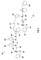
- a flooring 10 which has a layer structure. This comprises (from top to bottom) a transparent wear layer 12, which forms the top of the floor covering 10, an underlying decorative layer 14, which carries a decor, a glass fiber mat 16 under the decorative layer 14, a soft core 18 and a back layer 20, the completing the layer structure of the floor covering 10 toward the ground. Details of this layer structure will be described in more detail below.
- the wear layer 12 consists entirely of a polyurethane (PU) which has been synthesized from a high-grade aliphatic polyol. This aliphatic polyol is not a biogenic polyol. Furthermore, the wear layer 12 constructed in this way has high scratch resistance, ease of cleaning, UV stability, good impression behavior and resilience, and low emissions of toxic gases in the event of fire. Under the impression behavior is the behavior of the material under a mechanical load to understand. The surface of the flooring 10 is very resistant to such effects. If impressions form, they will almost completely recede when the mechanical load is removed.
- PU polyurethane
- the wear layer 12 in the present embodiment has a thickness between 0.1 and 0.5 mm.
- the decorative layer 14 located under the wear layer 12 consists of a decorative paper, that is to say a layer of cellulose impregnated with polyurethane.
- This polyurethane can also have been synthesized from a biogenic polyol, which is thus obtained from a renewable raw material.
- the decorative paper can have a basis weight between 35 and 80 g / m 2 and is printed on the top with the decor.
- the layer structure further comprises a glass fiber mat 16, which is arranged between the decorative layer 14 and the underlying core 18 is.
- This fiberglass mat is also impregnated with polyurethane, which is made from a biogenic polyol. It has a thickness between 0.2 mm and 0.5 mm.
- Both the core 18 and the backing layer 20 each consist of a polyurethane, which is obtained from an aromatic polyol of renewable resources. Although aromatic polyol is less valuable than aliphatic polyol, since the core 18 and the backing layer 20 are not exposed on the surface of the flooring 10, the use of materials that are less high grade can be accepted. Nevertheless, the core 18 has very good environmental compatibility properties, is very low in emissions and releases no toxic gases in case of fire.
- the core 18 may contain additional fillers.
- the backsheet 20 may be provided on its underside surface 22 with a structure that favors adhesion with an adhesive. In this way, the flooring 10 can be glued well with a substrate. The flooring 10 shown here can thus be adhered directly to a screed.
- the floor covering 10 itself as a floor plate which has a certain flexibility and elasticity. Also, this bottom plate can be provided with lateral locking profiles.
- it is a floor element for laying on a floor, comprising a lower-side support plate made of a wood material such as chip, MDF or HDF. It is also possible to form the carrier plate made of plastic. On its upper side, the carrier plate is laminated with the floor covering 10 according to the invention, as shown in the figure and described above. The backsheet 20 of this floor covering 10 is glued to the support plate.
- the flooring 10 on the top of the support plate has a thickness of about 1 mm.
- the flooring 10 as web material, which can be delivered rolled up and glued to the substrate.
- the flooring 10 in this variant has a total thickness of 1.8 to 3 mm.
- These panels are provided at their side edges with locking profiles such as profiles for adhesive-free installation.
- the plates have a total thickness of 3 to 8 mm and can have a width of about 2 m and then cut into different lengths and separated into different widths.
- Fig. 2 schematically shows a process flow for the production of the floor covering 10, for example as a sheet product.
- the process is divided into two different processes that can take place simultaneously.
- the wear layer 12 and the decorative layer 14 are produced and connected to the glass fiber mat 16, so that a layer composite is formed in Fig. 1 designated by the reference numeral 24.
- the core 18 and the backsheet 20 are made.
- the components of the floor covering 10 produced in the two processes are combined to form a unit, for example by gluing, so that the upper layer composite 24 is adhered to the core 18.
- the first process 50 is shown schematically in the upper part of the drawing, while the second process 52 is shown in the lower part of the figure.
- a first carrier tape 54 is first unwound from a roll 56 and fed to a station 58 for applying a polyurethane layer to the carrier tape 54.
- the polyurethane of this layer comes from a high quality aliphatic polyol.
- the polyurethane layer is applied to the carrier tape 54 in the desired thickness in this station 58.
- the resulting polyurethane layer forms the wear layer 12 Fig. 1 ,
- the carrier tape 54 with the wear layer 12 is then laminated in the subsequent station 60 with a pulp paper web 62. Before reaching the station 60, the wear layer 12 passes through a heating path 59. It should be noted that in this process, the wear layer 12 is located at the bottom and with the side in the use position according to FIG Fig. 2 forms the Nutzseite, rests on the carrier tape 54. The stratification in the first process thus takes place according to the orientation in FIG Fig. 1 from top to bottom, ie it is first the wear layer 12 is formed and then the decorative layer 14 and the glass fiber mat 16 applied.
- a glass fiber mat web 66 is unwound from a roll and placed on the pulp paper web 62, so that now on the carrier tape 54, the wear layer 12, the pulp paper web 62 to form the decorative layer 14 and the glass fiber mat web 66 are layered.
- This sheet is further transported to a station 68 in which the pulp paper web 62 and the glass fiber mat web 66 are impregnated with polyurethane. This in turn is done by a squeegee with a rubber lip, which introduces the polyurethane in the glass fiber mat web and the pulp paper web.
- the layer composite 24 that has been formed in this way is subsequently separated from the carrier tape 54, which is wound onto a roll 70. After the delamination, the layer composite 24 passes through a tempering path 72, on which it is brought to a predetermined temperature.
- a second carrier tape 74 is first unwound from a roll 76.
- This carrier tape 74 is structured on its surface. It passes through a station 77, at which a layer of polyurethane is applied to the surface-structured carrier tape 74, which originates from a biogenic aliphatic polyol, that is, from a polyol of renewable raw materials.
- the layer deposited in the station 77 forms the core 18 and the backing layer 20.
- the backing layer 20 is formed only by the patterned underside of the core 18, i. Core 18 and back layer 20 form a physical unit.
- the carrier tape 74 carries the core 18 with the backing layer 20 farther into a station 78 in which a laminating adhesive is applied to the upper side of the core 18.
- a laminating shaft 80 Downstream of the station 78, a laminating shaft 80 is arranged, through which the laminar composite 24 from the first process 50 is applied to the adhesive-provided upper side of the core 18.
- the layer composite 24 can be rolled up in the meantime and unwound again for the laminating process described here, which is described in US Pat Fig. 2 not shown.
- the structured carrier tape 74 Downstream of the laminating shaft 80, the structured carrier tape 74 is rewound and separated from the finished floor covering 10. This is then wound up as web material on a roll 84.
Description
- Die vorliegende Erfindung betrifft einen elastischen Bodenbelag, mit einem weichen Kern, einer auf dem Kern angeordneten Dekorschicht, einer auf der Dekorschicht liegenden transparenten Nutzschicht und einer unter dem Kern angeordneten Rückenschicht, wobei zumindest der Kern, die Nutzschicht und die Rückenschicht aus Polyurethan bestehen und zwischen dem Kern und der Dekorschicht eine Glasfasermatte einliegt.
- Flexible Bodenbeläge aus Kunststoffmaterialien sind schon seit langem bekannt. In der Vergangenheit wurden beispielsweise Bodenbeläge aus PVC oder Linoleum hergestellt. Thermoplastische, also bei Raumtemperatur hinreichend verformbare Bodenbeläge können als Bahnenware vertrieben werden und durch Aufkleben auf den Estrich verlegt werden. Möglich ist auch die Herstellung solcher Bodenbeläge in Form von Paneelen oder Fliesen, die an ihren Seitenkanten mit Verriegelungsprofilen ausgestattet sind, die eine Verbindung mit einem entsprechenden weiteren Paneel bzw. einer weiteren Fliese ermöglichen. Die Flexibilität des Belags erleichtert nicht nur das Verlegen, sondern kann zu positiven Eigenschaften im Gebrauch führen, wie z.B. einer guten Trittschalldämmung.
- Der Bodenbelag der hier vorliegenden Art hat einen Schichtaufbau. Er verfügt über einen weichen Kern, eine auf dem Kern angeordnete Dekorschicht, eine darauf liegende Nutzschicht und eine Rückenschicht, die unter dem Kern angeordnet ist. Seit einigen Jahren existieren Bodenbeläge, bei welchen zumindest der Kern, die Nutzschicht und die Rückenschicht aus Polyurethan (PU) hergestellt sind. Dies bringt verschiedenen Vorteile mit sich, wie etwa eine hohe Dimensionsstabilität, d.h. es treten geringe Veränderungen der Abmessungen des Bodenbelags bei Temperaturschwankungen auf. Ferner hat ein solcher Bodenbelag gute elastische Eigenschaften. Verformungen, wie sie durch mechanische Belastungen der Oberfläche bewirkt werden, bilden sich nahezu zu 100% zurück. Von besonderer Bedeutung ist außerdem die hohe Umweltverträglichkeit solcher Belege, die emissionsarm sein müssen und auch im Brandfall keine toxischen Gase freisetzen dürfen.
- Das Polyol, das als ein Ausgangsstoff für die Synthese der in diesen Bodenbelägen verwendeten Polyurethane verwendet wird, stammte bisher überwiegend aus petrochemischen Rohstoffen. Das höherwertige aliphatische Polyol wird vorwiegend für das Polyurethan der Nutzschicht eingesetzt, während das PU-Material für den Kern und die Rückenschicht gewöhnlich aus aromatischem Polyol gewonnen wird. Die Verwendung von aliphatischem Polyol führt zu Polyurethanen mit hoher Kratzfestigkeit, Reinigungsfreundlichkeit, UV-Stabilität, Eindruckverhalten, Rückstellverhalten und besseren Eigenschaften im Brandfall.
- Während die gesetzlichen Auflagen des Umweltschutzes strenger geworden sind und eine noch höhere Umweltverträglichkeit fordern, verlangt auch der Markt zunehmend nach Produkten mit hervorragender Umweltverträglichkeit im Wohnbereich. Diese Erfordernisse können von den bisherigen Bodenbelägen nicht ausreichend erfüllt werden.
- Aufgabe der vorliegenden Erfindung ist es daher, einen flexiblen Bodenbelag mit dem oben beschriebenen Schichtaufbau, der überwiegend oder vollständig aus Polyurethan besteht, bezüglich seiner Eigenschaften weiter zu verbessern, insbesondere bezüglich seiner Umweltverträglichkeit und seines Verhaltens im Brandfall, so dass noch weniger Emissionen freigesetzt werden. Die hervorragenden Gebrauchseigenschaften der bisher bekannten Bodenbeläge aus PU sollen hierbei nicht nur beibehalten, sondern sogar noch verbessert werden, insbesondere hinsichtlich der Dimensionsstabilität, des Eindruckverhaltens bei Belastungen und des Rückstellverhaltens.
- Diese Aufgaben werden erfindungsgemäß durch einen Bodenbelag mit den Merkmalen des Anspruchs 1 gelöst.
- Der Kern und die Rückenschicht des erfindungsgemäßen Bodenbelags bestehen aus einem Polyurethan, das aus einem aromatischen Polyol synthetisiert wird, welches aus nachwachsenden Rohstoffen gewonnen wird. Es handelt sich also hierbei um sogenannte biogene Polyole. Die hieraus hergestellten Polyurethane weisen bessere Eigenschaften hinsichtlich ihrer Umweltverträglichkeit auf als Polyol petrochemischen Ursprungs. Insbesondere sind sie sehr emissionsarm und entwickeln auch im Brandfall keine toxischen Gase. Es ist somit möglich, einen flexiblen Bodenbelag unter Verwendung von Polyurethan nahezu vollständig aus nachwachsenden Rohstoffen herzustellen und somit auch die Nachfrage nach umweltverträglichen und nachhaltigen Produkten zu befriedigen. Das Polyurethan der Nutzschicht ist aus einem aliphatischen Polyol hergestellt, während das Polyurethan des Kern und der Rückenschicht aus biogenem aromatischem Polyol synthetisiert ist.
- Zur weiteren Verbesserung der Dimensionsstabilität liegt zwischen dem Kern und der Dekorschicht zusätzlich eine Glasfasermatte ein, die das Eindruckverhalten und das Rückstellverhalten weiter verbessert und eine Ausdehnung und eine Schrumpfung des Belags bei einer Temperaturveränderung unterbindet. Die Dekorschicht besteht bei dem erfindungsgemäßen Bodenbelag aus einem Zellstoffpapier, das mit Polyurethan imprägniert ist. Auch dieses Polyurethan lässt sich aus einem biogenen Polyol synthetisieren.
- Gemäß einer besonderen Ausführungsform der vorliegenden Erfindung handelt es sich bei den nachwachsenden Rohstoffen um Pflanzenöl, insbesondere um Rizinusöl, Rapsöl oder Palmenöl.
- Gemäß einer weiter bevorzugten Ausführungsform ist die Rückenschicht an ihrer Unterseite mit einer Oberflächenstruktur versehen. Diese gewährleistet eine gute Verbindung zu einem Klebstoff, der zum Verkleben des Bodenbelags auf einem Untergrund wie z.B. Estrich verwendet wird.
- Gemäß einer weiteren bevorzugten Ausführungsform der Erfindung sind der Kern und die Rückenschicht einteilig ausgebildet und bestehen aus identischem Material. Die Rückenschicht stellt somit lediglich die Rückseite des Kerns dar.
- Vorzugsweise ist die Rückenschicht aus einer Polyolformulierung hergestellt, die affine Eigenschaften gegenüber herkömmlichen Dispersionsklebern hat, wie sie gewöhnlich für Bodenbeläge eingesetzt werden.
- Weiter vorzugsweise weist die Nutzschicht eine Dicke zwischen 0,1 mm und 0,5 mm auf, die Dekorschicht weist eine Dicke von etwa 0,2 mm auf, und die Glasfasermatte weist eine Dicke zwischen 0,2 mm und 0,5 mm auf.
- Gemäß einer weiteren bevorzugten Ausführungsform weist das Zellstoffpapier der Dekorschicht ein Flächengewicht zwischen 35 und 80 g/m2 auf.
- Gemäß einer Ausführungsform der vorliegenden Erfindung ist der Bodenbelag als aufrollbare Bahnenware hergestellt. Es ist somit möglich, den erfindungsgemäßen Bodenbelag als Bahnenware in Rollen auszuliefern und vor Ort bei der Verlegung entsprechend zuzuschneiden und aufzukleben. Diese Bahnenware kann beispielsweise eine Dicke von ca. 1 - 3 mm aufweisen.
- Gemäß einer alternativen Ausführungsform kann der Bodenbelag zu einer Platte zugeschnitten sein, die an seitlichen Kanten mit Verriegelungsprofilen zur Verbindung mit weiteren Platten versehen ist. Der Bodenbelag wird also in Form von Bodenpaneelen ausgeliefert, die mit Profilen ausgestattet sein können, die sich miteinander verbinden lassen. Diese Platte kann beispielsweise eine Dicke zwischen etwa 3 mm und 8 mm aufweisen.
- Die vorliegende Erfindung betrifft weiter vorzugsweise ein Bodenelement zur Verlegung auf einem Fußboden, wie etwa ein Bodenpaneel oder eine Bodenfliese, die eine Trägerplatte umfasst, die mit dem erfindungsgemäßen Bodenbelag kaschiert ist. Der erfindungsgemäße elastische Bodenbelag ist also unterseitig durch die Trägerplatte verstärkt. Die Trägerplatte kann aus einem relativ preiswerten Material wie etwa einem Holzwerkstoff hergestellt sein. Der Bodenbelag, der auf die Trägerplatte kaschiert ist, kann eine Dicke von ca. 1 mm aufweisen.
- Die Trägerplatte dieses Bodenelements ist vorzugsweise an seitlichen Kanten mit Verriegelungsprofilen zur Verbindung mit weiteren Platten versehen. Die Verlegung kann daher wie bei herkömmlichen Bodenpaneelen durch Verbindung der Verriegelungsprofile erfolgen.
- Ein Verfahren zur Herstellung des erfindungsgemäßen Bodenbelags ist gekennzeichnet durch einen ersten Prozess zur Bildung eines oberen Schichtverbunds, der die Nutzschicht, die Dekorschicht und die Glasfasermatte umfasst, und durch einen zweiten Prozess zur Bildung des Kerns in der Rückenschicht, sowie durch Zusammenfügen des oberen Schichtverbunds mit dem Kern. Der erste Prozess umfasst die folgenden Schritte:
- a) Auftragen einer Schicht aus Polyurethan aus einem aliphatischen Polyol auf ein erstes Trägerband zur Bildung der Nutzschicht,
- b) Auftragen einer Zellstoffpapierbahn zur Bildung der Dekorschicht auf die Nutzschicht,
- c) Auftragen einer Glasfasermattenbahn auf die Zellstoffpapierbahn,
- d) Imprägnieren der Zellstoffpapierbahn und der Glasfasermattenbahn mit Polyurethan.
- Der zweite Prozess umfasst den Schritt des Auftragens einer Schicht aus Polyurethan aus einem biogenen aromatischen Polyol auf ein oberflächenstrukturiertes zweites Trägerband zur Bildung der Rückenschicht und des Kerns.
- Vorzugsweise umfasst der erste Prozess nach dem Schritt d) die Schritte des Entfernen des ersten Trägerbands, und des Temperierens des oberen Schichtverbunds.
- Gemäß einer weiteren Ausführungsform dieses erfindungsgemäßen Verfahrens umfasst der zweite Prozess nach dem Schritt der Bildung der Rückenschicht und des Kerns den Schritt des Auftragens eines Kaschierklebers auf den Kern. Auf diese Weise wird der Kern für das Zusammenfügen mit dem oberen Schichtverbund vorbereitet.
- Weiter vorzugsweise wird nach dem Schritt des Auftragens des Kaschierklebers auf den Kern der obere Schichtverbund auf den Kern aufgeklebt.
- Im folgenden wird ein bevorzugtes Ausführungsbeispiel der Erfindung anhand der Zeichnung näher erläutert.
- Fig. 1
- zeigt einen schematischen Schnitt durch den Schichtaufbau einer Ausführungsform des erfindungsgemäßen elastischen Bodenbelags, und
- Fig. 2
- ist eine schematische Darstellung eines Verfahrensablaufs zur Herstellung des erfindungsgemäßen Bodenbelags.
- Im Schnitt ist in
Fig. 1 ein Bodenbelag 10 dargestellt, der einen Schichtaufbau aufweist. Dieser umfasst (von oben nach unten) eine transparente Nutzschicht 12, die die Oberseite des Bodenbelags 10 bildet, eine darunter liegende Dekorschicht 14, die ein Dekor trägt, eine Glasfasermatte 16 unter der Dekorschicht 14, einen weichen Kern 18 und eine Rückenschicht 20, die den Schichtaufbau des Bodenbelags 10 zum Untergrund hin abschließt. Einzelheiten dieses Schichtaufbaus sollen im folgenden näher beschrieben werden. - Die Nutzschicht 12 besteht vollständig aus einem Polyurethan (PU), das aus einem hochwertigen aliphatischen Polyol synthetisiert worden ist. Dieses aliphatische Polyol ist kein biogenes Polyol. Ferner weist die so aufgebaute Nutzschicht 12 eine hohe Kratzfestigkeit, Reinigungsfreundlichkeit, UV-Stabilität, ein gutes Eindruckverhalten und Rückstellverhalten und niedrige Emissionen toxischer Gase im Brandfall auf. Unter dem Eindruckverhalten ist das Verhalten des Materials bei einer mechanischen Belastung zu verstehen. Die Oberfläche des Bodenbelags 10 ist sehr widerstandsfähig gegenüber solchen Einwirkungen. Falls sich Eindrücke bilden, so werden diese nahezu vollständig wieder zurückgebildet, wenn die mechanische Last entfernt wird.
- Die Nutzschicht 12 weist bei der vorliegenden Ausführungsform eine Dicke zwischen 0,1 und 0,5 mm auf.
- Der unter Nutzschicht 12 befindliche Dekorfilm 14 besteht aus einem Dekorpapier, also einer Zellstoffschicht, die mit Polyurethan getränkt ist. Dieses Polyurethan kann ebenfalls aus einem biogenen Polyol synthetisiert worden sein, das also aus einem nachwachsenden Rohstoff gewonnen wird. Das Dekorpapier kann ein Flächengewicht zwischen 35 und 80 g/m2 haben und ist auf seiner Oberseite mit dem Dekor bedruckt.
- Zur Erhöhung der Dimensionsstabilität und zur weiteren Verbesserung des Eindruck- und Rückstellverhaltens des Bodenbelags 10 umfasst der Schichtaufbau ferner eine Glasfasermatte 16, die zwischen der Dekorschicht 14 und dem darunter liegenden Kern 18 angeordnet ist. Diese Glasfasermatte ist ebenfalls mit Polyurethan getränkt, das aus einem biogenen Polyol hergestellt wird. Sie hat eine Dicke zwischen 0,2 mm und 0,5 mm.
- Sowohl der Kern 18 als auch die Rückenschicht 20 bestehen jeweils aus einem Polyurethan, das aus einem aromatischen Polyol aus nachwachsenden Rohstoffen gewonnen wird. Aromatisches Polyol ist zwar weniger hochwertig als aliphatisches Polyol, doch da der Kern 18 und die Rückenschicht 20 nicht an der Oberfläche des Bodenbelags 10 frei liegen, kann hier auch die Verwendung von Werkstoffen in Kauf genommen werden, die weniger hochwertig sind. Dennoch hat der Kern 18 sehr gute Eigenschaften hinsichtlich der Umweltverträglichkeit, ist sehr emissionsarm und setzt im Brandfall keine toxischen Gase frei. Der Kern 18 kann zusätzliche Füllstoffe enthalten.
- Die Rückenschicht 20 kann auf ihrer unterseitigen Oberfläche 22 mit einer Struktur versehen sein, die das Anhaften mit einem Klebstoff begünstigt. Auf diese Weise kann der Bodenbelag 10 gut mit einem Untergrund verklebt werden. Der hier dargestellte Bodenbelag 10 kann somit unmittelbar auf einen Estrich aufgeklebt werden.
- In alternativen Ausführungsformen ist es denkbar, den Bodenbelag 10 nicht unmittelbar auf dem Untergrund, sondern auf einer Trägerplatte aufzubringen. Es entsteht hierdurch ein Bodenpaneel oder eine Bodenfliese, die mit dem erfindungsgemäßen Bodenbelag kaschiert ist und wie herkömmliche Bodenpaneele verlegt werden kann, beispielsweise mit Hilfe von Verriegelungsprofilen, die an den Seitenkanten der Paneele angebracht sind.
- In einer weiteren Ausführungsform ist es möglich, den Bodenbelag 10 selbst als Bodenplatte auszubilden, die eine gewisse Flexibilität und Elastizität aufweist. Auch diese Bodenplatte kann mit seitlichen Verriegelungsprofilen versehen sein.
- Weitere spezifische Ausführungsformen werden im folgenden noch näher genannt.
- Bei dieser Variante handelt es sich um ein Bodenelement zur Verlegung auf einem Fußboden, umfassend eine unterseitige Trägerplatte aus einem Holzwerkstoff wie Span, MDF oder HDF. Möglich ist auch, die Trägerplatte aus Kunststoff auszubilden. Auf ihrer Oberseite ist die Trägerplatte mit dem erfindungsgemäßen Bodenbelag 10 kaschiert, wie er in der Figur dargestellt und weiter oben beschrieben ist. Die Rückenschicht 20 dieses Bodenbelags 10 ist auf die Trägerplatte aufgeklebt.
- Der Bodenbelag 10 auf der Oberseite der Trägerplatte hat eine Stärke von ca. 1 mm.
- Hierbei handelt es sich um den Bodenbelag 10 als Bahnenware, die im aufgerollten Zustand angeliefert werden kann und mit dem Untergrund verklebt wird. Der Bodenbelag 10 hat in dieser Variante eine Gesamtstärke von 1,8 bis 3 mm.
- Hierbei handelt es sich um eine elastische Bodenplatte, die vollständig durch den Bodenbelag 10 selbst gebildet wird und deren Oberseite durch die Nutzschicht 12 gebildet wird, während die Unterseite 22 durch die Rückenschicht 20 gebildet wird. Diese Platten sind an ihren Seitenkanten mit Verriegelungsprofilen wie etwa Profilen zur klebstofffreien Verlegung versehen. Die Platten haben eine Gesamtstärke von 3 bis 8 mm und können eine Breite von ca. 2 m aufweisen und anschließend in unterschiedliche Längen gekappt und in unterschiedliche Breiten aufgetrennt werden.
-
Fig. 2 zeigt schematisch ein Verfahrensablauf zur Herstellung des Bodenbelags 10, beispielsweise als Bahnenware. - Das Verfahren ist in zwei verschiedene Prozesse aufgeteilt, die gleichzeitig stattfinden können. Im ersten Prozess werden die Nutzschicht 12 und die Dekorschicht 14 hergestellt und mit der Glasfasermatte 16 verbunden, so dass ein Schichtverbund entsteht, der in
Fig. 1 mit der Bezugsziffer 24 bezeichnet ist. In dem zweiten Prozess werden der Kern 18 und die Rückenschicht 20 hergestellt. Anschließend werden die in den beiden Prozessen hergestellten Bestandteile des Bodenbelags 10 zu einer Einheit verbunden, beispielsweise durch Verkleben, so dass der obere Schichtverbund 24 auf den Kern 18 aufgeklebt wird. - In
Fig. 2 ist der erste Prozess 50 schematisch im oberen Bereich der Zeichnung dargestellt, während der zweite Prozess 52 im unteren Figurenteil dargestellt ist. Im ersten Prozess 50 wird zunächst ein erstes Trägerband 54 von einer Rolle 56 abgewickelt und einer Station 58 zum Auftragen einer Polyurethanschicht auf das Trägerband 54 zugeführt. Das Polyurethan dieser Schicht stammt aus einem hochwertigen aliphatischen Polyol. Mittels einer Rakel wird in dieser Station 58 die Polyurethanschicht in der gewünschten Dicke auf das Trägerband 54 aufgetragen. Die so entstehende Polyurethanschicht bildet die Nutzschicht 12 ausFig. 1 . - Das Trägerband 54 mit der Nutzschicht 12 wird anschließend in der nachfolgenden Station 60 mit einer Zellstoffpapierbahn 62 kaschiert. Vor dem Erreichen der Station 60 durchläuft die Nutzschicht 12 eine Heizstrecke 59. Es ist anzumerken, dass sich in diesem Prozess die Nutzschicht 12 unten befindet und mit der Seite, die in der Gebrauchsposition gemäß
Fig. 2 die Nutzseite bildet, auf dem Trägerband 54 aufliegt. Die Schichtung im ersten Prozess erfolgt somit gemäß der Orientierung inFig. 1 von oben nach unten, d.h. es wird zunächst die Nutzschicht 12 gebildet und anschließend die Dekorschicht 14 und die Glasfasermatte 16 aufgetragen. - In der nachfolgenden Station 64 wird eine Glasfasermattenbahn 66 von einer Rolle abgewickelt und auf die Zellstoffpapierbahn 62 aufgelegt, so dass auf das Trägerband 54 nunmehr die Nutzschicht 12, die Zellstoffpapierbahn 62 zur Bildung der Dekorschicht 14 und die Glasfasermattenbahn 66 geschichtet sind. Dieses Schichtgebilde wird weiter zu einer Station 68 transportiert, in welcher die Zellstoffpapierbahn 62 und die Glasfasermattenbahn 66 mit Polyurethan getränkt werden. Dies geschieht wiederum durch eine Rakel mit einer Gummilippe, die das Polyurethan in die Glasfasermattenbahn und die Zellstoffpapierbahn einbringt.
- Der Schichtverbund 24, der so entstanden ist, wird anschließend vom Trägerband 54 getrennt, das auf eine Rolle 70 aufgewickelt wird. Nach der Delamination durchläuft der Schichtverbund 24 eine Temperierstrecke 72, auf der er auf eine vorbestimmte Temperatur gebracht wird.
- Im zweiten Prozess 52 wird zunächst ein zweites Trägerband 74 von einer Rolle 76 abgewickelt. Dieses Trägerband 74 ist auf seiner Oberfläche strukturiert. Es durchläuft eine Station 77, an der eine Schicht aus Polyurethan auf das oberflächenstrukturierte Trägerband 74 aufgetragen wird, das aus einem biogenen aliphatischen Polyol stammt, also aus einem Polyol aus nachwachsenden Rohstoffen. Die in der Station 77 aufgetragene Schicht bildet den Kern 18 und die Rückenschicht 20. Im vorliegenden Fall wird die Rückenschicht 20 lediglich durch die strukturierte Unterseite des Kerns 18 gebildet, d.h. Kern 18 und Rückenschicht 20 bilden eine körperliche Einheit.
- Das Trägerband 74 trägt den Kern 18 mit der Rückenschicht 20 weiter in eine Station 78, in der ein Kaschierkleber auf die Oberseite des Kerns 18 aufgetragen wird.
- Stromabwärts der Station 78 ist eine Kaschierwelle 80 angeordnet, durch welche der Schichtverbund 24 aus dem ersten Prozess 50 auf die mit dem Klebstoff versehene Oberseite des Kerns 18 aufgetragen wird. Es wird angemerkt, dass der Schichtverbund 24 zwischenzeitlich aufgerollt und für die hier beschriebenen Kaschiervorgang wieder abgewickelt werden kann, was in
Fig. 2 nicht dargestellt ist. Es ist allerdings auch möglich, den Schichtverbund 24 nach Durchlaufen der Kühlstrecke 72 ohne weiteres über Umlenkrollen oder dergleichen der Kaschierwelle 80 zuzuführen. Schematisch ist eine solche Umlenkrolle 82 inFig. 2 dargestellt. Das Umlenken muss im tatsächlichen Prozess allerdings ggf. auch das Drehen des Schichtverbunds 24 auf die richtige Seite beinhalten, was hier ebenfalls nicht näher gezeigt ist. - Stromabwärts der Kaschierwelle 80 wird das strukturierte Trägerband 74 wieder aufgewickelt und von dem fertigen Bodenbelag 10 getrennt. Dieser wird anschließend als Bahnenware auf eine Rolle 84 aufgewickelt.
Claims (15)
- Elastischer Bodenbelag (10), mit einem weichen Kern (18), einer auf dem Kern (18) angeordneten Dekorschicht (14), einer auf der Dekorschicht (14) liegenden Nutzschicht (12) und einer unter dem Kern (18) angeordneten Rückenschicht (20), wobei zumindest der Kern (18), die Nutzschicht (12) und die Rückenschicht (20) aus Polyurethan bestehen und zwischen dem Kern (18) und der Dekorschicht (14) eine Glasfasermatte (16) einliegt, dadurch gekennzeichnet,- dass die Dekorschicht (14) aus einem Zellstoffpapier besteht, das mit Polyurethan imprägniert ist,- dass die Nutzschicht (12) aus einem Polyurethan besteht, das aus einem aliphatischen Polyol gewonnen wird,- während der Kern (18) und die Rückenschicht (20) jeweils aus einem Polyurethan bestehen, das aus einem aromatischen Polyol aus nachwachsenden Rohstoffen gewonnen wird.
- Bodenbelag gemäß Anspruch 1, dadurch gekennzeichnet, dass es sich bei den nachwachsenden Rohstoffen um Pflanzenöl handelt, insbesondere um Rizinusöl, Rapsöl oder Palmenöl.
- Bodenbelag gemäß Anspruch 1 oder 2, dadurch gekennzeichnet, dass die Rückenschicht (20) an ihrer Unterseite (22) mit einer Oberflächenstruktur versehen ist.
- Bodenbelag gemäß einem der vorhergehenden Ansprüche, dadurch gekennzeichnet, dass der Kern (18) und die Rückenschicht (20) einteilig ausgebildet sind und aus identischem Material bestehen.
- Bodenbelag gemäß einem der vorhergehenden Ansprüche, dadurch gekennzeichnet, dass die Rückenschicht (20) aus Polyolformulierung hergestellt wird, die affine Eigenschaften gegenüber herkömmlichen Dispersionsklebern hat.
- Bodenbelag gemäß einem der vorhergehenden Ansprüche, dadurch gekennzeichnet, dass die Nutzschicht (12) eine Dicke zwischen 0,1 mm und 0,5 mm aufweist, die Dekorschicht (14) eine Dicke von etwa 0,2 mm aufweist, und die Glasfasermatte (16) eine Dicke zwischen 0,2 mm und 0,5 mm aufweist.
- Bodenbelag gemäß einem der vorhergehenden Ansprüche, dadurch gekennzeichnet, dass das Zellstoffpapier der Dekorschicht (14) ein Flächengewicht zwischen 35 und 80 g/m2 aufweist.
- Bodenbelag gemäß einem der vorhergehenden Ansprüche, dadurch gekennzeichnet, dass der Bodenbelag als aufrollbare Bahnenware hergestellt wird.
- Bodenbelag gemäß einem der Ansprüche 1 bis 7, dadurch gekennzeichnet, dass der Bodenbelag (10) zu einer Platte zugeschnitten ist, die an seitlichen Kanten mit Verriegelungsprofilen zur Verbindung mit weiteren Platten versehen ist.
- Bodenelement zur Verlegung auf einem Fußboden, wie etwa ein Bodenpaneel oder eine Bodenfliese, umfassend eine Trägerplatte, die mit einem Bodenbelag (10) gemäß einem der vorhergehenden Ansprüche kaschiert ist.
- Bodenelement gemäß Anspruch 10, dadurch gekennzeichnet, dass die Trägerplatte an seitlichen Kanten mit Verriegelungsprofilen zur Verbindung mit weiteren Platten versehen ist.
- Verfahren zur Herstellung eines Bodenbelags gemäß einem der Ansprüche 1 bis 9, gekennzeichnet durch einen ersten Prozess (50) zur Bildung eines oberen Schichtverbunds (24), der die Nutzschicht (12), die Dekorschicht (14) und die Glasfasermatte (16) umfasst, und durch einen zweiten Prozess (52) zur Bildung des Kerns (18) und der Rückenschicht (20), sowie durch Zusammenfügen des oberen Schichtverbunds (24) mit dem Kern (118), wobei der erste Prozess (50) die folgenden Schritte umfasst:a) Auftragen einer Schicht aus Polyurethan aus einem aliphatischen Polyol auf ein erstes Trägerband (54) zur Bildung der Nutzschicht (12),b) Auftragen einer Zellstoffpapierbahn (62) zur Bildung der Dekorschicht (14) auf die Nutzschicht (12),c) Auftragen einer Glasfasermattenbahn (66) auf die Zellstoffpapierbahn (62),d) Imprägnieren der Zellstoffpapierbahn (62) und der Glasfasermattenbahn (66) mit Polyurethan,
und der zweite Prozess (52) den folgenden Schritt umfasst:e) Auftragen einer Schicht aus Polyurethan aus einem biogenen aromatischen Polyol auf ein oberflächenstrukturiertes zweites Trägerband (74) zur Bildung der Rückenschicht (12) und des Kerns (18). - Verfahren gemäß Anspruch 12, dadurch gekennzeichnet, dass der erste Prozess (50) nach dem Schritt d) die folgenden weiteren Schritte umfasst:f) Entfernen des ersten Trägerbands (54), undg) Temperieren des oberen Schichtverbunds (24).
- Verfahren gemäß Anspruch 12 oder 13, dadurch gekennzeichnet, dass der zweite Prozess (52) nach dem Schritt e) den folgenden weiteren Schritt umfasst:h) Auftragen eines Kaschierklebers auf den Kern (18).
- Verfahren gemäß Anspruch 14, dadurch gekennzeichnet, dass nach Schritt h) der obere Schichtverbund (24) auf den Kern (18) aufgeklebt wird.
Priority Applications (5)
| Application Number | Priority Date | Filing Date | Title |
|---|---|---|---|
| NO15160021A NO2907655T3 (de) | 2011-10-31 | 2011-10-31 | |
| DK15160021.0T DK2907655T3 (da) | 2011-10-31 | 2011-10-31 | Elastisk gulvbelægning |
| PL15160021T PL2907655T3 (pl) | 2011-10-31 | 2011-10-31 | Elastyczna okładzina podłogowa |
| PL11788034T PL2755818T3 (pl) | 2011-10-31 | 2011-10-31 | Elastyczna wykładzina podłogowa |
| EP15160021.0A EP2907655B1 (de) | 2011-10-31 | 2011-10-31 | Elastischer bodenbelag |
Applications Claiming Priority (1)
| Application Number | Priority Date | Filing Date | Title |
|---|---|---|---|
| PCT/EP2011/005493 WO2013064160A1 (de) | 2011-10-31 | 2011-10-31 | Elastischer bodenbelag |
Related Child Applications (1)
| Application Number | Title | Priority Date | Filing Date |
|---|---|---|---|
| EP15160021.0A Division EP2907655B1 (de) | 2011-10-31 | 2011-10-31 | Elastischer bodenbelag |
Publications (2)
| Publication Number | Publication Date |
|---|---|
| EP2755818A1 EP2755818A1 (de) | 2014-07-23 |
| EP2755818B1 true EP2755818B1 (de) | 2015-03-25 |
Family
ID=45044493
Family Applications (2)
| Application Number | Title | Priority Date | Filing Date |
|---|---|---|---|
| EP20110788034 Active EP2755818B1 (de) | 2011-10-31 | 2011-10-31 | Elastischer bodenbelag |
| EP15160021.0A Active EP2907655B1 (de) | 2011-10-31 | 2011-10-31 | Elastischer bodenbelag |
Family Applications After (1)
| Application Number | Title | Priority Date | Filing Date |
|---|---|---|---|
| EP15160021.0A Active EP2907655B1 (de) | 2011-10-31 | 2011-10-31 | Elastischer bodenbelag |
Country Status (9)
| Country | Link |
|---|---|
| US (1) | US20140255659A1 (de) |
| EP (2) | EP2755818B1 (de) |
| JP (1) | JP5898769B2 (de) |
| DK (2) | DK2907655T3 (de) |
| ES (2) | ES2536326T3 (de) |
| NO (1) | NO2907655T3 (de) |
| PL (2) | PL2907655T3 (de) |
| PT (1) | PT2755818E (de) |
| WO (1) | WO2013064160A1 (de) |
Cited By (2)
| Publication number | Priority date | Publication date | Assignee | Title |
|---|---|---|---|---|
| DE102016105046A1 (de) | 2016-03-18 | 2017-09-21 | Guido Schulte | Plattenförmiges Bauelement |
| DE102017115185A1 (de) | 2017-07-06 | 2019-01-10 | Guido Schulte | Plattenförmiges Bauelement und Verfahren zu dessen Herstellung |
Families Citing this family (12)
| Publication number | Priority date | Publication date | Assignee | Title |
|---|---|---|---|---|
| BE1019501A5 (nl) * | 2010-05-10 | 2012-08-07 | Flooring Ind Ltd Sarl | Vloerpaneel en werkwijze voor het vervaardigen van vloerpanelen. |
| BE1019331A5 (nl) | 2010-05-10 | 2012-06-05 | Flooring Ind Ltd Sarl | Vloerpaneel en werkwijzen voor het vervaardigen van vloerpanelen. |
| DK3055127T3 (da) | 2013-10-11 | 2017-11-27 | Wpt Gmbh | Elastisk gulvbelægning i form af en metervare, der kan rulles på |
| ES2642966T3 (es) * | 2013-10-11 | 2017-11-20 | Wpt Gmbh | Placa de suelo elástica |
| CN104631770A (zh) * | 2015-02-06 | 2015-05-20 | 蔡燕明 | 具有改良稳定结构的塑胶地板 |
| EP3168363A1 (de) | 2015-11-12 | 2017-05-17 | Interprint GmbH | Verfahren zur herstellung eines imprägnats und eines verbundwerkstoffs, sowie verwendung von polyurethan als imprägnierungsmittel |
| KR101804756B1 (ko) * | 2015-12-09 | 2017-12-05 | 주식회사 녹수 | 직물 소재를 포함하는 바닥재 타일 및 이의 제조 방법 |
| CN107013007A (zh) * | 2017-03-24 | 2017-08-04 | 滁州市春洲木业有限公司 | 一种高强度塑胶地板 |
| US10563412B1 (en) * | 2018-11-30 | 2020-02-18 | Cary Paik | Acoustic flooring assembly |
| DE202019104040U1 (de) | 2019-07-22 | 2019-08-20 | Hoffmann Gmbh | Gefedertes Boden- oder Wandelement |
| DE102019128881A1 (de) * | 2019-10-25 | 2021-04-29 | Windmöller Gmbh | Dimensionsstabiler Bodenbelag und Verfahren zu seiner Herstellung |
| CN115667343A (zh) * | 2020-01-24 | 2023-01-31 | 塔伊普科有限公司 | 可持续弹性板材 |
Family Cites Families (30)
| Publication number | Priority date | Publication date | Assignee | Title |
|---|---|---|---|---|
| US3747037A (en) * | 1968-01-11 | 1973-07-17 | Gen Electric | Petroleum based oil modified castor oil-urethane composition for electrical potting |
| JPH05280182A (ja) * | 1992-03-31 | 1993-10-26 | Takiron Co Ltd | 床 材 |
| JPH0732518A (ja) * | 1993-07-16 | 1995-02-03 | Dairin Shoji:Kk | 建築用複合建材 |
| JPH08284385A (ja) * | 1995-04-12 | 1996-10-29 | Daicel Chem Ind Ltd | フローリング下地材およびその製造法 |
| JP2000289138A (ja) * | 1999-04-07 | 2000-10-17 | Hitachi Kasei Unit Co Ltd | 模様入り化粧パネル及びその製造法 |
| US6440538B1 (en) * | 2000-04-03 | 2002-08-27 | Lg Chem Ltd. | Abrasion resistant laminate |
| US6841023B2 (en) * | 2001-02-21 | 2005-01-11 | Pergo (Europe) Ab | Process for the manufacturing of an improved core for decorative laminates and a decorative laminate obtained by the process |
| US6907700B2 (en) * | 2001-03-15 | 2005-06-21 | Tarkett Sommer | Floor with floating support |
| DE10229473A1 (de) * | 2001-12-17 | 2003-06-26 | Bayer Ag | Verbundteile aus Deckschichten und Polyurethan-Sandwichmaterialien und ihre Herstellung |
| US20030143910A1 (en) * | 2002-01-31 | 2003-07-31 | Mashburn Larry E. | Carpet backings prepared from vegetable oil-based polyurethanes |
| KR100451482B1 (ko) * | 2002-04-24 | 2004-10-11 | 우진물산 주식회사 | 페놀복합수지를 이용한 바닥재 |
| US20050208275A1 (en) * | 2002-05-30 | 2005-09-22 | Kazuhiro Abe | Decorative material and decorative sheet |
| US6875500B2 (en) * | 2002-10-15 | 2005-04-05 | Mcgrath, Jr. William H. | Flexible flooring system |
| US20070044412A1 (en) * | 2003-06-24 | 2007-03-01 | Forster Cheryl M | Interlocking floorboard tile system and method of manufacture |
| KR200370449Y1 (ko) * | 2004-06-22 | 2004-12-17 | 주식회사 엘지화학 | 합성수지를 이용한 표면층 및 목질계 보드를 포함하는마루바닥재 |
| KR100716404B1 (ko) * | 2004-09-21 | 2007-05-11 | 주식회사 엘지화학 | 인쇄목질 단판층을 기재층에 적층한 강화 온돌마루 |
| DE102005006532A1 (de) * | 2005-02-11 | 2006-08-24 | Kaindl Flooring Gmbh | Paneel mit dekorativer Schicht |
| JP2007085149A (ja) * | 2005-09-22 | 2007-04-05 | Hiroshima Kasei Ltd | ポリ塩化ビニル系床材 |
| JP4775633B2 (ja) * | 2005-11-29 | 2011-09-21 | Dic株式会社 | 積層体、及び積層体の製造方法 |
| JP4731357B2 (ja) * | 2006-02-28 | 2011-07-20 | 大日本印刷株式会社 | 化粧シート |
| JP5248004B2 (ja) * | 2006-10-03 | 2013-07-31 | 住友林業株式会社 | 床材及びその製造方法 |
| DE102006058655B4 (de) * | 2006-12-11 | 2010-01-21 | Ulrich Windmöller Consulting GmbH | Bodenpaneel |
| US20090062432A1 (en) * | 2007-06-11 | 2009-03-05 | Doesburg Van I | Novel polyurethane compositions including castor oil |
| RU2483867C2 (ru) * | 2007-11-19 | 2013-06-10 | СераЛок Инновейшн Белджиум БВБА | Панели на основе древесных волокон с износостойкой поверхностью |
| US9446564B2 (en) * | 2009-03-03 | 2016-09-20 | Schneller Llc | Polyurethane based rigid flooring laminate |
| JP5280301B2 (ja) * | 2009-06-01 | 2013-09-04 | 東リ株式会社 | 駐車場用シート |
| US8741085B2 (en) * | 2009-08-21 | 2014-06-03 | Awi Licensing Company | Method of making a resilient floor tile |
| US8468770B2 (en) * | 2009-09-23 | 2013-06-25 | Textile Rubber & Chemical Company, Inc. | Floor covering product and method of using same |
| JP5517537B2 (ja) * | 2009-09-25 | 2014-06-11 | 株式会社リンレイ | 可剥離性床用被覆組成物 |
| CN101793086A (zh) * | 2010-03-03 | 2010-08-04 | 江小敏 | 一种环保热塑性聚氨酯地砖及其生产工艺 |
-
2011
- 2011-10-31 EP EP20110788034 patent/EP2755818B1/de active Active
- 2011-10-31 PL PL15160021T patent/PL2907655T3/pl unknown
- 2011-10-31 NO NO15160021A patent/NO2907655T3/no unknown
- 2011-10-31 ES ES11788034.4T patent/ES2536326T3/es active Active
- 2011-10-31 DK DK15160021.0T patent/DK2907655T3/da active
- 2011-10-31 PL PL11788034T patent/PL2755818T3/pl unknown
- 2011-10-31 ES ES15160021.0T patent/ES2644067T3/es active Active
- 2011-10-31 JP JP2014526390A patent/JP5898769B2/ja not_active Expired - Fee Related
- 2011-10-31 WO PCT/EP2011/005493 patent/WO2013064160A1/de active Application Filing
- 2011-10-31 PT PT117880344T patent/PT2755818E/pt unknown
- 2011-10-31 EP EP15160021.0A patent/EP2907655B1/de active Active
- 2011-10-31 DK DK11788034.4T patent/DK2755818T3/en active
- 2011-10-31 US US14/234,287 patent/US20140255659A1/en not_active Abandoned
Cited By (6)
| Publication number | Priority date | Publication date | Assignee | Title |
|---|---|---|---|---|
| DE102016105046A1 (de) | 2016-03-18 | 2017-09-21 | Guido Schulte | Plattenförmiges Bauelement |
| EP3235970A1 (de) | 2016-03-18 | 2017-10-25 | Guido Schulte | Plattenförmiges bauelement |
| EP3235973A1 (de) | 2016-03-18 | 2017-10-25 | Guido Schulte | Plattenförmiges bauelement |
| DE202017006917U1 (de) | 2016-03-18 | 2018-10-30 | Guido Schulte | Plattenförmiges Bauelement |
| DE202017006916U1 (de) | 2016-03-18 | 2018-10-30 | Guido Schulte | Plattenförmiges Bauelement |
| DE102017115185A1 (de) | 2017-07-06 | 2019-01-10 | Guido Schulte | Plattenförmiges Bauelement und Verfahren zu dessen Herstellung |
Also Published As
| Publication number | Publication date |
|---|---|
| NO2907655T3 (de) | 2018-01-27 |
| DK2755818T3 (en) | 2015-04-20 |
| PL2755818T3 (pl) | 2015-07-31 |
| JP5898769B2 (ja) | 2016-04-06 |
| EP2907655A1 (de) | 2015-08-19 |
| DK2907655T3 (da) | 2017-11-06 |
| PL2907655T3 (pl) | 2018-01-31 |
| ES2536326T3 (es) | 2015-05-22 |
| EP2907655B1 (de) | 2017-08-30 |
| WO2013064160A1 (de) | 2013-05-10 |
| US20140255659A1 (en) | 2014-09-11 |
| ES2644067T3 (es) | 2017-11-27 |
| EP2755818A1 (de) | 2014-07-23 |
| JP2014527131A (ja) | 2014-10-09 |
| PT2755818E (pt) | 2015-07-22 |
Similar Documents
| Publication | Publication Date | Title |
|---|---|---|
| EP2755818B1 (de) | Elastischer bodenbelag | |
| DE60116523T2 (de) | Baustoffplatte mit schutzfolie und verfahren zu ihrer herstellung | |
| WO2014090939A1 (de) | Verfahren zur herstellung einer mit einer dekorschicht versehenen werkstoffplatte | |
| EP3055130B1 (de) | Elastische bodenplatte | |
| EP3055127B1 (de) | Elastischer bodenbelag in form einer aufrollbaren bahnenware | |
| EP2572063B1 (de) | Fussbodenpaneel mit einer eine korkschicht umfassenden nutzschicht | |
| DE2166968B2 (de) | Verfahren zum Herstellen einer Verbundbahn | |
| EP2688722B1 (de) | Verfahren zum bekanten von holzwerkstoffplatten | |
| EP2983914B1 (de) | Verfahren zum herstellen eines eine dekorschicht aufweisenden elastomer-bodenbelags und elastomer-bodenbelag mit einer dekorschicht | |
| DE19910389C2 (de) | Trägerloses Linoleum-Flächengebilde und Verfahren zu dessen Herstellung | |
| DE2461397A1 (de) | Schaumstoff-verbundbelag | |
| DE3142587A1 (de) | Dekoratives laminat und verfahren zu dessen herstellung | |
| EP0411653B1 (de) | Sporthallenboden | |
| CH643186A5 (de) | Verfahren zur herstellung eines kunststoffaufklebeerzeugnisses. | |
| DE102016225575A1 (de) | Verfahren zur Herstellung von Bodenelementen und Bodenelemente | |
| AT509199B1 (de) | Verfahren zur herstellung einer pressstoffplatte | |
| DE2052581C3 (de) | Fußbodenbelag in Form eines Mehrschichtkörpers | |
| EP2177355A2 (de) | Verfahren zum Herstellen einer Trägerplatte und Trägerplatte | |
| DE1923289B2 (de) | Verfahren zum Herstellen eines textilähnlichen Materials | |
| EP4060141B1 (de) | Selbststabilisierte untergrundverlegeeinheit und untergrundbelag | |
| DD296981A5 (de) | Sporthallenboden | |
| DE4003847A1 (de) | Verfahren zur herstellung eines sportbodens | |
| DE202008006999U1 (de) | Mehrlagige Decklagenkanten-Sichtkante | |
| DE102012002369A1 (de) | Vorgekleistertes Flächengebilde, insbesondere Bahnenware, insbesondere Tapetenbahn, sowie Verfahren zu dessen Herstellung | |
| AT8849U1 (de) | Dämmplatte und verfahren zur herstellung derselben |
Legal Events
| Date | Code | Title | Description |
|---|---|---|---|
| PUAI | Public reference made under article 153(3) epc to a published international application that has entered the european phase |
Free format text: ORIGINAL CODE: 0009012 |
|
| 17P | Request for examination filed |
Effective date: 20140213 |
|
| AK | Designated contracting states |
Kind code of ref document: A1 Designated state(s): AL AT BE BG CH CY CZ DE DK EE ES FI FR GB GR HR HU IE IS IT LI LT LU LV MC MK MT NL NO PL PT RO RS SE SI SK SM TR |
|
| GRAJ | Information related to disapproval of communication of intention to grant by the applicant or resumption of examination proceedings by the epo deleted |
Free format text: ORIGINAL CODE: EPIDOSDIGR1 |
|
| GRAP | Despatch of communication of intention to grant a patent |
Free format text: ORIGINAL CODE: EPIDOSNIGR1 |
|
| DAX | Request for extension of the european patent (deleted) | ||
| INTG | Intention to grant announced |
Effective date: 20141007 |
|
| GRAS | Grant fee paid |
Free format text: ORIGINAL CODE: EPIDOSNIGR3 |
|
| GRAA | (expected) grant |
Free format text: ORIGINAL CODE: 0009210 |
|
| AK | Designated contracting states |
Kind code of ref document: B1 Designated state(s): AL AT BE BG CH CY CZ DE DK EE ES FI FR GB GR HR HU IE IS IT LI LT LU LV MC MK MT NL NO PL PT RO RS SE SI SK SM TR |
|
| REG | Reference to a national code |
Ref country code: GB Ref legal event code: FG4D Free format text: NOT ENGLISH |
|
| REG | Reference to a national code |
Ref country code: CH Ref legal event code: EP |
|
| REG | Reference to a national code |
Ref country code: CH Ref legal event code: NV Representative=s name: TROESCH SCHEIDEGGER WERNER AG, CH |
|
| REG | Reference to a national code |
Ref country code: DK Ref legal event code: T3 Effective date: 20150413 |
|
| REG | Reference to a national code |
Ref country code: IE Ref legal event code: FG4D Free format text: LANGUAGE OF EP DOCUMENT: GERMAN |
|
| REG | Reference to a national code |
Ref country code: NL Ref legal event code: T3 |
|
| REG | Reference to a national code |
Ref country code: DE Ref legal event code: R096 Ref document number: 502011006400 Country of ref document: DE Effective date: 20150507 |
|
| REG | Reference to a national code |
Ref country code: AT Ref legal event code: REF Ref document number: 717609 Country of ref document: AT Kind code of ref document: T Effective date: 20150515 |
|
| REG | Reference to a national code |
Ref country code: ES Ref legal event code: FG2A Ref document number: 2536326 Country of ref document: ES Kind code of ref document: T3 Effective date: 20150522 |
|
| REG | Reference to a national code |
Ref country code: SE Ref legal event code: TRGR |
|
| REG | Reference to a national code |
Ref country code: NO Ref legal event code: T2 Effective date: 20150325 |
|
| REG | Reference to a national code |
Ref country code: PT Ref legal event code: SC4A Free format text: AVAILABILITY OF NATIONAL TRANSLATION Effective date: 20150615 |
|
| PG25 | Lapsed in a contracting state [announced via postgrant information from national office to epo] |
Ref country code: LT Free format text: LAPSE BECAUSE OF FAILURE TO SUBMIT A TRANSLATION OF THE DESCRIPTION OR TO PAY THE FEE WITHIN THE PRESCRIBED TIME-LIMIT Effective date: 20150325 Ref country code: HR Free format text: LAPSE BECAUSE OF FAILURE TO SUBMIT A TRANSLATION OF THE DESCRIPTION OR TO PAY THE FEE WITHIN THE PRESCRIBED TIME-LIMIT Effective date: 20150325 |
|
| REG | Reference to a national code |
Ref country code: PL Ref legal event code: T3 |
|
| REG | Reference to a national code |
Ref country code: LT Ref legal event code: MG4D |
|
| PG25 | Lapsed in a contracting state [announced via postgrant information from national office to epo] |
Ref country code: RS Free format text: LAPSE BECAUSE OF FAILURE TO SUBMIT A TRANSLATION OF THE DESCRIPTION OR TO PAY THE FEE WITHIN THE PRESCRIBED TIME-LIMIT Effective date: 20150325 Ref country code: GR Free format text: LAPSE BECAUSE OF FAILURE TO SUBMIT A TRANSLATION OF THE DESCRIPTION OR TO PAY THE FEE WITHIN THE PRESCRIBED TIME-LIMIT Effective date: 20150626 Ref country code: LV Free format text: LAPSE BECAUSE OF FAILURE TO SUBMIT A TRANSLATION OF THE DESCRIPTION OR TO PAY THE FEE WITHIN THE PRESCRIBED TIME-LIMIT Effective date: 20150325 |
|
| REG | Reference to a national code |
Ref country code: FR Ref legal event code: PLFP Year of fee payment: 5 |
|
| PG25 | Lapsed in a contracting state [announced via postgrant information from national office to epo] |
Ref country code: SK Free format text: LAPSE BECAUSE OF FAILURE TO SUBMIT A TRANSLATION OF THE DESCRIPTION OR TO PAY THE FEE WITHIN THE PRESCRIBED TIME-LIMIT Effective date: 20150325 Ref country code: RO Free format text: LAPSE BECAUSE OF FAILURE TO SUBMIT A TRANSLATION OF THE DESCRIPTION OR TO PAY THE FEE WITHIN THE PRESCRIBED TIME-LIMIT Effective date: 20150325 Ref country code: CZ Free format text: LAPSE BECAUSE OF FAILURE TO SUBMIT A TRANSLATION OF THE DESCRIPTION OR TO PAY THE FEE WITHIN THE PRESCRIBED TIME-LIMIT Effective date: 20150325 Ref country code: EE Free format text: LAPSE BECAUSE OF FAILURE TO SUBMIT A TRANSLATION OF THE DESCRIPTION OR TO PAY THE FEE WITHIN THE PRESCRIBED TIME-LIMIT Effective date: 20150325 |
|
| PG25 | Lapsed in a contracting state [announced via postgrant information from national office to epo] |
Ref country code: IS Free format text: LAPSE BECAUSE OF FAILURE TO SUBMIT A TRANSLATION OF THE DESCRIPTION OR TO PAY THE FEE WITHIN THE PRESCRIBED TIME-LIMIT Effective date: 20150725 |
|
| REG | Reference to a national code |
Ref country code: DE Ref legal event code: R097 Ref document number: 502011006400 Country of ref document: DE |
|
| PLBE | No opposition filed within time limit |
Free format text: ORIGINAL CODE: 0009261 |
|
| STAA | Information on the status of an ep patent application or granted ep patent |
Free format text: STATUS: NO OPPOSITION FILED WITHIN TIME LIMIT |
|
| 26N | No opposition filed |
Effective date: 20160105 |
|
| PG25 | Lapsed in a contracting state [announced via postgrant information from national office to epo] |
Ref country code: SI Free format text: LAPSE BECAUSE OF FAILURE TO SUBMIT A TRANSLATION OF THE DESCRIPTION OR TO PAY THE FEE WITHIN THE PRESCRIBED TIME-LIMIT Effective date: 20150325 Ref country code: LU Free format text: LAPSE BECAUSE OF FAILURE TO SUBMIT A TRANSLATION OF THE DESCRIPTION OR TO PAY THE FEE WITHIN THE PRESCRIBED TIME-LIMIT Effective date: 20151031 |
|
| PG25 | Lapsed in a contracting state [announced via postgrant information from national office to epo] |
Ref country code: MC Free format text: LAPSE BECAUSE OF FAILURE TO SUBMIT A TRANSLATION OF THE DESCRIPTION OR TO PAY THE FEE WITHIN THE PRESCRIBED TIME-LIMIT Effective date: 20150325 |
|
| REG | Reference to a national code |
Ref country code: IE Ref legal event code: MM4A |
|
| REG | Reference to a national code |
Ref country code: FR Ref legal event code: PLFP Year of fee payment: 6 |
|
| PG25 | Lapsed in a contracting state [announced via postgrant information from national office to epo] |
Ref country code: IE Free format text: LAPSE BECAUSE OF NON-PAYMENT OF DUE FEES Effective date: 20151031 |
|
| PG25 | Lapsed in a contracting state [announced via postgrant information from national office to epo] |
Ref country code: HU Free format text: LAPSE BECAUSE OF FAILURE TO SUBMIT A TRANSLATION OF THE DESCRIPTION OR TO PAY THE FEE WITHIN THE PRESCRIBED TIME-LIMIT; INVALID AB INITIO Effective date: 20111031 Ref country code: BG Free format text: LAPSE BECAUSE OF FAILURE TO SUBMIT A TRANSLATION OF THE DESCRIPTION OR TO PAY THE FEE WITHIN THE PRESCRIBED TIME-LIMIT Effective date: 20150325 Ref country code: SM Free format text: LAPSE BECAUSE OF FAILURE TO SUBMIT A TRANSLATION OF THE DESCRIPTION OR TO PAY THE FEE WITHIN THE PRESCRIBED TIME-LIMIT Effective date: 20150325 |
|
| PG25 | Lapsed in a contracting state [announced via postgrant information from national office to epo] |
Ref country code: CY Free format text: LAPSE BECAUSE OF FAILURE TO SUBMIT A TRANSLATION OF THE DESCRIPTION OR TO PAY THE FEE WITHIN THE PRESCRIBED TIME-LIMIT Effective date: 20150325 |
|
| PG25 | Lapsed in a contracting state [announced via postgrant information from national office to epo] |
Ref country code: MT Free format text: LAPSE BECAUSE OF FAILURE TO SUBMIT A TRANSLATION OF THE DESCRIPTION OR TO PAY THE FEE WITHIN THE PRESCRIBED TIME-LIMIT Effective date: 20150325 |
|
| REG | Reference to a national code |
Ref country code: FR Ref legal event code: PLFP Year of fee payment: 7 |
|
| PGFP | Annual fee paid to national office [announced via postgrant information from national office to epo] |
Ref country code: NO Payment date: 20171020 Year of fee payment: 7 Ref country code: TR Payment date: 20171030 Year of fee payment: 7 Ref country code: DK Payment date: 20171024 Year of fee payment: 7 |
|
| PGFP | Annual fee paid to national office [announced via postgrant information from national office to epo] |
Ref country code: IT Payment date: 20171020 Year of fee payment: 7 Ref country code: ES Payment date: 20171103 Year of fee payment: 7 Ref country code: PT Payment date: 20171025 Year of fee payment: 7 |
|
| REG | Reference to a national code |
Ref country code: DE Ref legal event code: R082 Ref document number: 502011006400 Country of ref document: DE Representative=s name: WAGNER ALBIGER & PARTNER PATENTANWAELTE MBB, DE |
|
| PG25 | Lapsed in a contracting state [announced via postgrant information from national office to epo] |
Ref country code: MK Free format text: LAPSE BECAUSE OF FAILURE TO SUBMIT A TRANSLATION OF THE DESCRIPTION OR TO PAY THE FEE WITHIN THE PRESCRIBED TIME-LIMIT Effective date: 20150325 |
|
| REG | Reference to a national code |
Ref country code: FR Ref legal event code: PLFP Year of fee payment: 8 |
|
| PG25 | Lapsed in a contracting state [announced via postgrant information from national office to epo] |
Ref country code: AL Free format text: LAPSE BECAUSE OF FAILURE TO SUBMIT A TRANSLATION OF THE DESCRIPTION OR TO PAY THE FEE WITHIN THE PRESCRIBED TIME-LIMIT Effective date: 20150325 |
|
| REG | Reference to a national code |
Ref country code: DK Ref legal event code: EBP Effective date: 20181031 |
|
| REG | Reference to a national code |
Ref country code: NO Ref legal event code: MMEP |
|
| PG25 | Lapsed in a contracting state [announced via postgrant information from national office to epo] |
Ref country code: NO Free format text: LAPSE BECAUSE OF NON-PAYMENT OF DUE FEES Effective date: 20181031 Ref country code: PT Free format text: LAPSE BECAUSE OF NON-PAYMENT OF DUE FEES Effective date: 20190430 |
|
| PG25 | Lapsed in a contracting state [announced via postgrant information from national office to epo] |
Ref country code: DK Free format text: LAPSE BECAUSE OF NON-PAYMENT OF DUE FEES Effective date: 20181031 Ref country code: IT Free format text: LAPSE BECAUSE OF NON-PAYMENT OF DUE FEES Effective date: 20181031 |
|
| REG | Reference to a national code |
Ref country code: ES Ref legal event code: FD2A Effective date: 20191203 |
|
| PG25 | Lapsed in a contracting state [announced via postgrant information from national office to epo] |
Ref country code: ES Free format text: LAPSE BECAUSE OF NON-PAYMENT OF DUE FEES Effective date: 20181101 |
|
| REG | Reference to a national code |
Ref country code: CH Ref legal event code: PL |
|
| PG25 | Lapsed in a contracting state [announced via postgrant information from national office to epo] |
Ref country code: LI Free format text: LAPSE BECAUSE OF NON-PAYMENT OF DUE FEES Effective date: 20191031 Ref country code: CH Free format text: LAPSE BECAUSE OF NON-PAYMENT OF DUE FEES Effective date: 20191031 |
|
| PG25 | Lapsed in a contracting state [announced via postgrant information from national office to epo] |
Ref country code: TR Free format text: LAPSE BECAUSE OF NON-PAYMENT OF DUE FEES Effective date: 20181031 |
|
| PGFP | Annual fee paid to national office [announced via postgrant information from national office to epo] |
Ref country code: PL Payment date: 20221024 Year of fee payment: 12 Ref country code: BE Payment date: 20221020 Year of fee payment: 12 |
|
| PGFP | Annual fee paid to national office [announced via postgrant information from national office to epo] |
Ref country code: NL Payment date: 20231023 Year of fee payment: 13 |
|
| PGFP | Annual fee paid to national office [announced via postgrant information from national office to epo] |
Ref country code: GB Payment date: 20231025 Year of fee payment: 13 |
|
| PGFP | Annual fee paid to national office [announced via postgrant information from national office to epo] |
Ref country code: SE Payment date: 20231025 Year of fee payment: 13 Ref country code: FR Payment date: 20231023 Year of fee payment: 13 Ref country code: FI Payment date: 20231023 Year of fee payment: 13 Ref country code: DE Payment date: 20231106 Year of fee payment: 13 Ref country code: AT Payment date: 20231019 Year of fee payment: 13 |
|
| PGFP | Annual fee paid to national office [announced via postgrant information from national office to epo] |
Ref country code: PL Payment date: 20231023 Year of fee payment: 13 Ref country code: BE Payment date: 20231023 Year of fee payment: 13 |