EP2755225B1 - Electron-microscopic examination method for examining a living biological sample - Google Patents
Electron-microscopic examination method for examining a living biological sample Download PDFInfo
- Publication number
- EP2755225B1 EP2755225B1 EP12829935.1A EP12829935A EP2755225B1 EP 2755225 B1 EP2755225 B1 EP 2755225B1 EP 12829935 A EP12829935 A EP 12829935A EP 2755225 B1 EP2755225 B1 EP 2755225B1
- Authority
- EP
- European Patent Office
- Prior art keywords
- sample
- electron microscope
- composition
- peg
- observation
- Prior art date
- Legal status (The legal status is an assumption and is not a legal conclusion. Google has not performed a legal analysis and makes no representation as to the accuracy of the status listed.)
- Active
Links
Images


Classifications
-
- G—PHYSICS
- G01—MEASURING; TESTING
- G01N—INVESTIGATING OR ANALYSING MATERIALS BY DETERMINING THEIR CHEMICAL OR PHYSICAL PROPERTIES
- G01N23/00—Investigating or analysing materials by the use of wave or particle radiation, e.g. X-rays or neutrons, not covered by groups G01N3/00 – G01N17/00, G01N21/00 or G01N22/00
- G01N23/22—Investigating or analysing materials by the use of wave or particle radiation, e.g. X-rays or neutrons, not covered by groups G01N3/00 – G01N17/00, G01N21/00 or G01N22/00 by measuring secondary emission from the material
- G01N23/225—Investigating or analysing materials by the use of wave or particle radiation, e.g. X-rays or neutrons, not covered by groups G01N3/00 – G01N17/00, G01N21/00 or G01N22/00 by measuring secondary emission from the material using electron or ion
- G01N23/2251—Investigating or analysing materials by the use of wave or particle radiation, e.g. X-rays or neutrons, not covered by groups G01N3/00 – G01N17/00, G01N21/00 or G01N22/00 by measuring secondary emission from the material using electron or ion using incident electron beams, e.g. scanning electron microscopy [SEM]
- G01N23/2252—Measuring emitted X-rays, e.g. electron probe microanalysis [EPMA]
-
- G—PHYSICS
- G01—MEASURING; TESTING
- G01N—INVESTIGATING OR ANALYSING MATERIALS BY DETERMINING THEIR CHEMICAL OR PHYSICAL PROPERTIES
- G01N23/00—Investigating or analysing materials by the use of wave or particle radiation, e.g. X-rays or neutrons, not covered by groups G01N3/00 – G01N17/00, G01N21/00 or G01N22/00
- G01N23/02—Investigating or analysing materials by the use of wave or particle radiation, e.g. X-rays or neutrons, not covered by groups G01N3/00 – G01N17/00, G01N21/00 or G01N22/00 by transmitting the radiation through the material
- G01N23/04—Investigating or analysing materials by the use of wave or particle radiation, e.g. X-rays or neutrons, not covered by groups G01N3/00 – G01N17/00, G01N21/00 or G01N22/00 by transmitting the radiation through the material and forming images of the material
-
- G—PHYSICS
- G01—MEASURING; TESTING
- G01N—INVESTIGATING OR ANALYSING MATERIALS BY DETERMINING THEIR CHEMICAL OR PHYSICAL PROPERTIES
- G01N1/00—Sampling; Preparing specimens for investigation
- G01N1/28—Preparing specimens for investigation including physical details of (bio-)chemical methods covered elsewhere, e.g. G01N33/50, C12Q
- G01N1/2853—Shadowing samples
-
- G—PHYSICS
- G01—MEASURING; TESTING
- G01N—INVESTIGATING OR ANALYSING MATERIALS BY DETERMINING THEIR CHEMICAL OR PHYSICAL PROPERTIES
- G01N1/00—Sampling; Preparing specimens for investigation
- G01N1/28—Preparing specimens for investigation including physical details of (bio-)chemical methods covered elsewhere, e.g. G01N33/50, C12Q
- G01N1/44—Sample treatment involving radiation, e.g. heat
-
- G—PHYSICS
- G01—MEASURING; TESTING
- G01N—INVESTIGATING OR ANALYSING MATERIALS BY DETERMINING THEIR CHEMICAL OR PHYSICAL PROPERTIES
- G01N23/00—Investigating or analysing materials by the use of wave or particle radiation, e.g. X-rays or neutrons, not covered by groups G01N3/00 – G01N17/00, G01N21/00 or G01N22/00
- G01N23/22—Investigating or analysing materials by the use of wave or particle radiation, e.g. X-rays or neutrons, not covered by groups G01N3/00 – G01N17/00, G01N21/00 or G01N22/00 by measuring secondary emission from the material
- G01N23/225—Investigating or analysing materials by the use of wave or particle radiation, e.g. X-rays or neutrons, not covered by groups G01N3/00 – G01N17/00, G01N21/00 or G01N22/00 by measuring secondary emission from the material using electron or ion
-
- H—ELECTRICITY
- H01—ELECTRIC ELEMENTS
- H01J—ELECTRIC DISCHARGE TUBES OR DISCHARGE LAMPS
- H01J37/00—Discharge tubes with provision for introducing objects or material to be exposed to the discharge, e.g. for the purpose of examination or processing thereof
- H01J37/02—Details
- H01J37/20—Means for supporting or positioning the object or the material; Means for adjusting diaphragms or lenses associated with the support
-
- H—ELECTRICITY
- H01—ELECTRIC ELEMENTS
- H01J—ELECTRIC DISCHARGE TUBES OR DISCHARGE LAMPS
- H01J37/00—Discharge tubes with provision for introducing objects or material to be exposed to the discharge, e.g. for the purpose of examination or processing thereof
- H01J37/26—Electron or ion microscopes; Electron or ion diffraction tubes
-
- G—PHYSICS
- G01—MEASURING; TESTING
- G01N—INVESTIGATING OR ANALYSING MATERIALS BY DETERMINING THEIR CHEMICAL OR PHYSICAL PROPERTIES
- G01N2223/00—Investigating materials by wave or particle radiation
- G01N2223/60—Specific applications or type of materials
- G01N2223/612—Specific applications or type of materials biological material
-
- H—ELECTRICITY
- H01—ELECTRIC ELEMENTS
- H01J—ELECTRIC DISCHARGE TUBES OR DISCHARGE LAMPS
- H01J2237/00—Discharge tubes exposing object to beam, e.g. for analysis treatment, etching, imaging
- H01J2237/20—Positioning, supporting, modifying or maintaining the physical state of objects being observed or treated
- H01J2237/2002—Controlling environment of sample
- H01J2237/2003—Environmental cells
- H01J2237/2004—Biological samples
Definitions
- the present disclosure relates to an electron microscopic observation method for observing a biological sample in the shape as it is in a scanning electron microscope, a transmission electron microscope, or the like, and a composition for evaporation suppression under vacuum, a scanning electron microscope, and a transmission electron microscope used in the method.
- a sample is put under vacuum in order to perform sample observation using a scanning electron microscope and a transmission electron microscope, and thus the sample is desired to be resistant to vacuum and to be imparted with electrical conductivity required to acquire an image thereof.
- the preparation of a sample for scanning electron microscope is performed as follows.
- the sample is dehydrated by prior vacuum drying, and then an electrically conducting material (platinum, carbon, gold, palladium, osmium, and the like) is coated on the surface of the sample by means of vapor deposition, sputtering or the like in order to impart electrical conductivity and improve the generation efficiency of secondary electrons.
- an electrically conducting material platinum, carbon, gold, palladium, osmium, and the like
- conductive film coating with an electrically conductive material is required for materials deteriorating in resistance to vacuum, that is, materials deformed by vacuum drying or irradiation of an electron beam in a vacuum at the time of electron microscopic observation.
- Biological/living body samples contain a large amount of water, and thus prior vacuum drying is required in many cases. For this reason, the surface shape thereof is significantly deformed in some cases, and thus it is difficult to observe a biological/living body sample in the living state as it is using an electron microscope.
- Water-retaining state of wet samples such as gelatinous materials and foods can be observed at room temperature using a low vacuum SEM or a cryo-SEM, an environmental SEM (ESEM), and the like. Using these techniques, not only wet samples but also untreated samples can be observed. However, a high vacuum is required in order to perform observation at a high magnification, and thus the sample must be resistant to vacuum or electrically conductive. For that reason, it is difficult to acquire an image in the living state as it is at a high magnification in the observation of a biological/living body sample, as well.
- Patent Literature 1 and Non Patent Literature 2 disclose that a wet sample is scanning electron microscopically observed using an ionic liquid.
- Non Patent Literature 2 discloses the application of the method on cells, as well.
- Patent Literature 2 discloses a method using the technique on ionic liquids in transmission electron microscopic observation.
- the environment for electron microscopic measurement is a vacuum state and thus a sample is put in an extremely dry state. For this reason, deformation or transformation of the sample occurs and thus it is not possible to observe the sample in a state near the living state as it is.
- the hydrated sample is instantly frozen when put under vacuum, and cryohydrate of the sample brings about deformation or transformation of the sample. Hence, it is not possible to observe the sample in a state near the original state.
- a biological sample since the biological sample is put under vacuum, oxygen supply from the outer system is interrupted and thus the sample falls into hypoxia. In addition, the biological sample is put in a dry state, and thus becomes like a dried fish (a squid becomes like a dried squid). As a result, it is difficult for a biological sample to be in the living state as it is in the microscope body of an electron microscope.
- An electron beam is irradiated in order to perform electron microscopic observation, but it is required to acquire an electron microscopic image of a biological sample in the living state as it is without bringing about the deformation and/or degeneration of the biological sample by an electrical factor or thermal factor caused by this electron beam irradiation.
- barrier performance a technique, in which a film is formed on the surface of a sample by means of spin coating, vapor deposition, coating, or the like using an organic material, an inorganic material, or an organic/inorganic hybrid material, thereby imparting barrier performance to the sample, has been suggested.
- this barrier performance has been no example applying this barrier performance to the sample preparation for electron microscope so far.
- the invention was made in view of the circumstances described above, and an object thereof is to provide an electron microscopic observation method capable of not deforming a sample and of suppressing damage of the state of a sample itself even under vacuum, the disclosure also provides a composition for evaporation suppression under vacuum, a scanning electron microscope, and a transmission electron microscope used in the method.
- another object of the invention is to provide an electron microscopic observation method capable of observing a biological sample as it is alive and a situation that the biological sample is moving using an electron microscope, the disclosure also provides a composition for
- the living biological sample observation method by an electron microscope comprises applying a composition for evaporation suppression including at least one kind selected from an amphiphilic compound, oils and fats, and an ionic liquid to a body surface of a living biological sample; irradiating the sample applied with the composition for evaporation suppression with an electron beam or plasma to form a polymerized film on the surface of the sample as a thin film and covering the sample with the polymerized film, wherein the sample is provided with motility by suppressing decrease in temperature associated with evaporation from the inside of the sample body, the morphology of the sample is preserved as it is, and an internal body temperature of the sample which enables the sample to be active, is maintained even under vacuum, and displaying an electron microscopic image of the sample covered with the polymerized film and accommodated in a sample chamber under vacuum as it is alive on a display device.
- a composition for evaporation suppression including at least one kind selected from an amphiphilic compound, oils and fats, and an ionic liquid to a
- the polymerized film is formed on a surface of a sample as a thin film by a polymerization reaction by irradiating the sample with an electron beam for sample observation in the sample chamber of an electron microscope.
- the polymerized film is formed on a surface of a sample as a thin film by a polymerization reaction by irradiating the sample with an electron beam or plasma other than the electron beam for sample observation in advance before sample observation by electron microscope.
- the composition for evaporation suppression includes at least one kind selected from an amphiphilic compound, a metal compound, and a saccharide.
- an electron microscopic image of a hydrated sample in a wet state is displayed on the displaying device without accompanying collapse of the hydrated sample.
- vacuum means, for example, a range of 10 -1 Pa or less, in addition 10 -2 Pa to 10 -4 Pa, and particularly 10 -4 Pa to 10 -8 Pa.
- composition for evaporation suppression described herein forms a barrier on the surface of a biological sample to provide electron microscopic observation, in which the biological sample is introduced in the microscope body of an electron microscope in the living state as it is and observed in the living state as it is.
- This barrier has a function (water barrier performance), by which the water in the living being is not dried but preserved in a liquid state as it is even under vacuum, and a function (gas barrier performance), by which the deaeration of gaseous substances such as oxygen in vivo is suppressed.
- this barrier has a function (electrical conductivity/heat resistance), by which electrical and thermal deformation ad transformation caused by an electron beam irradiated to acquire an electron microscopic image, as well.
- an amphiphilic compound, oils and fats, and an ionic liquid retains (has a water/gas barrier function) water and air (gas) under vacuum.
- a uniform protective film is formed by pouring this liquid on a biological sample, and thus water/gas barrier performance under atmospheric pressure and vacuum is exerted.
- this liquid when this liquid was employed for the observation of a biological sample using an electron microscope, it was possible to acquire a SEM image of a situation that a biological sample is moving since the biological sample was not dried in the microscope body of an electron microscope, was not accompanied with deformation and transformation, and was preserved in the living state as it is. Even at high magnification, there was no deformation or degeneration caused by an electron beam as well, and thus it was possible to observe a situation that a biological sample is moving. In addition, a favorable SEM observation was possible since charge up did not occur as well.
- an amphiphilic compound, a combination of an amphiphilic compound and a metal compound or a saccharide, fats and oils, an ionic liquid, or fats and oils are forms a protective film imparting a water/gas barrier performance.
- the inventors advance this water/gas barrier performance as the Surface Shielding Effect (SS effect).
- amphiphilic compound a combination of an amphiphilic compound and a metal compound or a saccharide, fats and oils, or an ionic liquid imparts the Surface Shielding Effect (SS effect), and it is also found out that a protective film formed of these materials functions as a multifunctional barrier film since electrical conductivity is imparted and thermal damage caused by an electron beam is suppressed in addition to these barrier performances.
- SS effect Surface Shielding Effect
- the invention it is possible to observe a biological/living body sample in the living state as it is using an electron microscope.
- the invention provides not only a solution for electron microscopic observation of a biological/living body sample but also a constitution of the SS solution imparting the Surface Shielding Effect (SS effect) widely.
- the SS solution imparting the Surface Shielding Effect contains an amphiphilic compound, contains an amphiphilic compound of a main component and a metal compound or a saccharide, contains fats and oils, or contains an ionic liquid, but the following items such as an amino acid and a derivative thereof, a vitamin and a derivative thereof, an inorganic salt, a metal oxide, and a fatty acid and a derivative thereof, a conductive polymer, and a nanoclay can be added to the SS solution at an arbitrary proportion, and then the resultant SS solution can be used in various applications.
- the SS solution contains an amphipilic compound as a main component (base material).
- a surfactant can be used as the amphiphilic compound.
- Surfactants are roughly classified into an anionic surfactant, a cationic surfactant, a nonionic surfactant, a zwitterionic surfactant, and a naturally derived surfactant, and the like according to the molecular structure thereof.
- Surfactants are used in a variety of fields such as industry, food, and medical supplies, and the barrier performance can be basically exerted to a certain extent although any kinds of surfactants are used.
- the anionic surfactant is classified into, for example, a carboxylic acid type, a sulfuric acid ester type, a sulfonic acid type, and a phosphoric acid ester type.
- specific examples thereof may include sodium dodecyl sulfate, sodium laurate, ⁇ -sulfofatty acid methyl ester sodium salt, sodium dodecylbenzenesulfonate, and sodium dodecylethoxylate sulfate.
- sodium dodecylbenzenesulfonate is preferably used.
- the cationic surfactant is classified into, for example, a quaternary ammonium salt type, an alkyl amine type, and a heterocyclic amine type. Specific examples thereof may include stearyl trimethyl ammonium chloride, distearyl dimethyl ammonium chloride, didecyl dimethyl ammonium chloride, cetyl trimethyl pyridinium chloride, and dodecyl dimethyl benzyl ammonium chloride.
- examples of the nonionic surfactant may include polyoxyethylene alkyl ether, polyoxyethylene hydrogenated castor oil, a polyoxyethylene mono-fatty acid ester, a polyoxyethylene sorbitan mono-fatty acid ester, a sucrose fatty acid ester, a polyglycerol fatty acid ester, an alkylpolyglycoside, and a N-methyl-alkylglucamide.
- Triton TM X Triton TM X-100 and the like
- Pluronic (R) Pluronic (R) F-123, F-68, and the like
- Tween Teween 20, 40, 60, 65, 80, 85, and the like
- Brij R
- Brij R
- Span Span 20, 40, 60, 80, 83, and 85
- examples of the zwitterionic surfactant may include lauryl betaine, dodecyl dimethyl amino methyl sulfopropyl betaine, and 3-(tetradecyl dimethyl aminio)propane-1-sulfonate, and 3-[(3-cholamidopropyl)dimethylammonio]-1-propanesulfonate (CHAPS), 3-[(3-cholamidopropyl)dimethylammonio]-2-hydroxy-1-propanesulfonate (CHAPSO), and the like are preferably used.
- lauryl betaine dodecyl dimethyl amino methyl sulfopropyl betaine
- 3-(tetradecyl dimethyl aminio)propane-1-sulfonate 3-[(3-cholamidopropyl)dimethylammonio]-1-propanesulfonate (CHAPS), 3-[(3-cholamidopropyl)dimethylammonio]-2
- lecithin and saponin are preferable.
- the compounds termed as lecithin specifically phosphatidylcholine, phosphatidylethanolamine, phosphatidylinositol, phosphatidylserine, phosphatidic acid, phosphatidylglycerol, and the like are preferable.
- saponin Quillaja saponin is preferable.
- surfactants described above as an amphiphilic compound derived from microorganisms (biosurfactant), Rhamnolipid, Sophorolipids, mannosylerythritol lipids, and the like are preferably used.
- examples of a surfactant which is particularly used for cosmetics, may include almond oil PEG-6, Na acyl(C12, 14) aspartate, TEA acyl(C12, 14) aspartate, araezeth-20, stearyl alcohol, sodium alkyl(C11, 13, 15) sulfate, TEA alkyl(C11, 13, 15) sulfate, potassium alky(C11, 13, 15) phosphate, DEA alkyl(C12, 13) sulfate, sodium alkyl(C12, 13) sulfate, TEA alkyl(C12, 13) sulfate, alkyl(C12, 14, 16) ammonium sulfate, alkyl(C12-14) oxyhydroxypropyl arginine hydrochloride, alkyl(C12-14) diamino ethyl
- a fluorosurfactant can also be used in addition to the surfactants described above.
- Specific examples of the fluorosurfactant may include ammonium heptadecafluoro-1-octanesulfonate, ammonium pentadecafluorooctanate, heptadecafluorooctanesulfonic acid, lithium heptadecafluoro-1-octanesulfonate, pentadecafluorooctanoic acid, pentadecafluorooctanoic acid hydrate, and potassium heptadecafluoro-1-octanesulfonate.
- the following surfactants can also be used in addition to the surfactants described above.
- examples thereof may include an anionic surfactant such as a N-long chain acyl amino acid salt such as a N-long chain neutral amino acid salt such as a N-long chain acyl glutamic acid salt, a N-long chain acyl aspartic acid salt, a N- long chain acyl glycine salt, a N-long chain acyl alanine salt, a N-long chain acyl threonine salt, and a N-long chain acyl sarcosine salt, a N-long chain fatty acid acyl-N-methyl taurine salt, an alkyl sulfate and an alkylene oxide adduct thereof, a fatty acid amide ether sulfate, a metal salt of fatty acid, a sulfosuccinic acid-based surfactant, an alkyl phosphate and an alkylene oxide adduct thereof
- the SS solution contains an amphiphilic compound and a metal compound.
- a metal compound a substance containing a metal ion can be widely used.
- the metal compound may be a salt consisting of a cation and an anion (monosalt), or a salt consisting of two or more of cations and anions (double salt).
- the metal compound may be a compound such as an oxide, a hydroxide, a halide, a sulfate salt, a nitrate salt, a carbonate salt, and an acetate salt.
- Specific examples thereof may include sodium chloride, magnesium chloride, calcium chloride, sodium bicarbonate, potassium chloride, strontium chloride, lithium chloride, hafnium chloride, iron chloride, aluminum chloride, zinc chloride, copper chloride, cobalt chloride, magnesium sulfate, and magnesium carbonate.
- the metal compound may be a metal oxide.
- a metal alkoxide is a compound indicated by MOR, and consists of a metal (M) and an alkoxide (RO - ) (R represents a hydrocarbon).
- metal (M) may include silicon, titanium, aluminum, boron, zirconium, boron, vanadium, tungsten, phosphorus, germanium, indium, hafnium, and molybdenum.
- a metal alkoxide is obtained from various kinds of alcohols. These metal alkoxides may be used as it is, or a reaction product obtained by performing a sol-gel reaction of these metal alkoxides in the presence of an acid or an alkali may be used. As the metal alkoxide, two or more kinds may be mixed together instead of using a single component.
- the metal compound may be a metal complex.
- the SS solution contains an amphiphilic compound and a saccharide.
- a saccharide With regard to the combination of a saccharide and an amphiphilic compound, imparting the SS effect is newly described herein.
- the saccharide a monosaccharide, a disaccharide, an oligosaccharide, a polysaccharide, and a derivative thereof are blended.
- the monosaccharide may include glucose and fructose
- examples of the disaccharide may include sucrose.
- polysaccharide examples include heparin, chondroitin sulfate, pullulan, pectin, guar gum, xanan gum, carrageenan, propylene glycol, and carboxymethyl cellulose, and a polysaccharide such as pullulan is particularly preferable.
- a polysaccharide such as pullulan is particularly preferable.
- caramel, honey, beeswax may be used.
- the SS solution may contain fats and oils.
- silicon oil may be exemplified. Silicon oil functions as a water retaining agent preserving the aqueous environment of the tissue or cell of a biological sample, dynamic observation of the biological sample as it is alive is achieved by this function. In other words, silicon oil can be used as a material having a barrier performance, by which the water of tissue or cell is not lost even under vacuum.
- silicon oil for example, silicon oil having a viscosity of 1 to 100,000 mPa ⁇ s at 25°C can be used.
- silicon oil having a viscosity of 1 to 100,000 mPa ⁇ s at 25°C can be used.
- composition for evaporation suppression (SS solution) described herein which uses silicon oil, preferably contains the silicon oil 10% by weight or more with respect to the total amount of the composition, and the components exemplified below may be blended as a component other than the silicon oil.
- the SS solution may contain an ionic liquid.
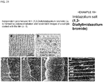
- Examples of the ionic liquid may include imidazolium salts, pyridinium salts, piperidinium salts, pyrrolidinium salts, quaternary ammonium salts, phosphoniums, sulfoniums, and pyrazoliums.
- imidazolium salts may include 1-alkyl-3-alkylimidazolium, 1,3-dimethylimidazolium, 1-ethyl-3-methylimidazolium, 1-butyl-3-methylimidazolium, 1-hexyl-3-methylimidazolium, 3-methyl-1-octylimidazolium, 1-dodecyl-3-methylimidazolium, 1-dodecyl-3-methylimidazolium, 1-methyl-3-tetradecylimidazolium, 1-hexadecyl-3-imidazolium, 1-octadecyl-3-methylimidazolium, 1-allyl-3-methylimidazolium, 1-allyl-3-methylimidazolium, 1-allyl-3-methylimidazolium, 1-allyl-3-methylimidazolium, 1-allyl-3-ethylimidazolium, 1-allyl-3-butylimidazolium, 1,3-
- Examples of the 1-alkyl-2,3-dialkylimidazolium salt may include 1-ethyl-2,3-dimethylimidazolium, 1,2,3-triethylimidazolium, 1,2-dimethyl-3-propylimidazolium, 1-butyl-2,3-dimethylimidazolium, 1-hexyl-2,3-dimethylimidazolium, and 1,3- dodecyl-2-methylimidazolium.
- Examples of the pyridinium salts may include 1-methylpyridinium, 1-ethylpyridinium, 1-butylpyridinium, 1-hexylpyridinium, 1-ethyl-3-methylpyridinium, 1-methyl-4-methylpyridinium, 1-propyl-4-methylpyridinium, 1-propyl-3-methylpyridinium, 1-butyl-2-methylpyridinium, 1-butyl-3-methylpyridinium, 1-ethyl-3-hydroxymethyl, and 1-(3-hydroxypropyl)pyridinium.
- Examples of the piperidinium salts may include 1-methyl-1-propylpiperidinium, 1-butyl-1-methylpiperidinium, and 1-(methoxyethyl)-1-methylpiperidinium.
- Examples of the pyrrolidinium salts may include 1,1-dimethylpyrrolidinium, 1-ethyl-1-methylpyrrolidinium, 1-methyl-1-propylpyrrolidinium, 1-butyl-1-methylpyrrolidinium, and 1-(methoxyethyl)-1-methylpyrrolidinium.
- Examples of the quaternary ammonium salts may include choline, N,N-diethyl-N-methyl-N-(2-methoxyethyl)ammonium, and trimethylamine oxide in addition to tetramethylammonium, tetrabutylammonium, butyltrimethylammonium, ethyl-dimethyl-propyl ammonium, tributylmethylammonium, methyltrioctylammonium, and 2-hydroxyethylammonoum.
- Examples of the phosphoniums may include tetrabutylphosphonium, tributylhexadecylphosphonium, triethylpentylphosphonium, triethyloctylphosphonium, tetraoctylphosphonium, tri-isobutylmethylphosphonium, tributyltetradecylphosphonium, and triethyltetradecylphosphonium.
- Examples of the sulfoniums may include triethylsulfonium and diethylmethylsulnium.
- Examples of the pyrazoliums may include guanidinium and N-(methoxyethyl)-N-methylmorpholinium in addition to 1-ethyl-2,3,5-trimethylpyrazolium, 1-propyl-2,3,5-trimethylpyrazolium, and 1-butyl-2,3,5-trimethylpyrazolium.
- the anionic moiety may be the following ones.
- the anionic moiety may be, in addition to a saturated/unsaturated hydrocarbon group, an aromatic hydrocarbon group, an ether group, an alkyl hydroxyl group, chloride ion, bromide ion, ioride ion, acetate ion, lactate ion, methoxy sulfonate ion, ethoxy sulfonate ion, dimethoxy phosphate ion, n-butyl sulfonate ion, diethoxy phosphate ion, ethyl sulfonate ion, n-hexyl phosphate ion, hydrogen phosphate ion, thiocyanate ion, octyl sulfonate ion, 2-(2-methoxyethoxy)ethyl sulfate
- the anionic moiety may be an arbitrary amino acid obtained by ion exchange through the method disclosed in J. Am. Chem. Soc., 2005, 127, 2398 to 2399 .
- the amino acid descried herein may be a monomer, or a dipeptide or an oligopeptide.
- a counter ion is in a proportion of 1 : 1 with respect to a imidazolium salt in Non Patent Literature 3, but the proportion of 1 : 1 is not required with regard to an ionic liquid in the invention.
- the SS solution may contain an amphiphilic compound, or may contain an amphiphilic compound and a metal compound or may contain a saccharide, or may contain fats and oils, or may contain an ionic liquid, and an amino acid exemplified in the following item and a derivative thereof, a polyhydric alcohol, a vitamin and a derivative thereof, a fatty acid and a derivative thereof, a polymeric material, and the like may be added at an arbitrary proportion in addition to these components.
- an amino acid and a derivative thereof may be blended.
- the amino acid may include a simple substance such as glycine, alanine, valine, leucine, isoleucine, serine, threonine, cysteine, methionine, asparagine, glutamine, proline, phenylalanine, tyrosine, tryptophan, aspartic acid, glutamic acid, lysine, arginine, and histidine, a hydrochloride, a substance formed by bonding of two or more molecules, and a polymer thereof. These may be a single of one kind or a mixture of two or more kinds. Furthermore, these may be a derivative thereof.
- a polyhydric alcohol and a derivative thereof may be blended.
- a substance having a hydroxyl group in the molecule and a low vapor pressure is preferable.
- Specific examples thereof may include a substance other than the naturally derived amphiphilic compounds, such as glycerin, a triglyceride, polyresorcinol, a polyphenol, tannic acid, and urushiol, and particularly, tannic acid is preferably used.
- a vitamin and a derivative thereof, and a substance related thereto may be blended.
- Specific examples thereof may include vitamin B 1 , vitamin B 2 , vitamin B 3 , vitamin B 5 , vitamin B 6 , vitamin B 7 , vitamin B 9 , vitamin B 12 , vitamin A, vitamin D, vitamin E, and vitamin K, or a derivative thereof.
- retinal, ⁇ -carotene, vitamin B 3 (nicotinic acid, nicotinamide), vitamin B 6 (pyridoxine, pyridoxal, pyridoxamine), and vitamin B 9 (folic acid) are preferable.
- examples of the vitamin derivative may include D-araboascorbic acid, setflavin T, 4-deoxypyridoxine hydrochloride, dibenzoyl thiamine, 2,6-di-O-palmitoyl-L-ascorbic acid, flavin adenine dinucleotide disodium hydrate, (+)-5,6-O-isopropylidene-L-ascorbic acid, 6-O-palmitoyl-L-ascorbic acid, proflavin hemisulfate hydrate, pyridoxal hydrochloride, pyridoxal 5-phosphate monohydrate, pyridoxine 3,4-dipalmitate, sodium isoascorbate monohydrate, thiamine disulfide hydrate, and thiamine disulfide nitrate.
- Examples of the substance related to vitamin may include choline chloride, choline bromide, choline dihydrogen citrate, choline bitartrate coenzyme Q10, coenzyme Qo, methionine methylsulfonyl chloride, and inositols.
- polymeric material examples include polyvinyl alcohol, Teflon (registered trademark), polyvinylidene fluoride, tetraethoxysilane, tetramethoxysilane, titanium isopropoxide, and zirconium butoxide.
- the ionic liquids described above may be additionally blended with other essential components.
- the following components may be blended in addition to the components exemplified above, such as an amphiphilic compound, a metal compound, a saccharide, and the like.
- Coordination compound crown ether, cyclodextrin, cyclic tetramer of resorcinol, calixarene, a dendrimer and the like.
- Fatty acid and derivative thereof Fatty acid and derivative thereof: linolic acid, oleic acid, palmitic acid, linoleic acid, and the like.
- saccharide and fatty acid Derivative of saccharide and fatty acid: hyaluronic acid, ceramide, an amphiphilic compound, collagen, an amino acid, an essential oil, petrolatum, and the like.
- Gelatinizer poly(pyridinium-1,4-diyliminocarbonyl-1,4-phenylenemethylene chloride and the like.
- Colorant paprika pigment, malachite green, and the like in addition to chlorophyll, carotenoids (lycopene), phycobilin, melanin, and the like.
- Conductive polymer Nafion and the like in addition to polyacetylene, polyaniline, polythiophene, and the like.
- Nanoclay a commercially available product having a trade name of Nanoclay Nanomer (R) Laponite or montmorillonite and the like.
- Matrix material used as a reagent for mass spectrometry mainly in MALDI method: 3-amino-4-hydroxybenzoic acid, sinapic acid, esculetin, 4-hydroxy-azobenzene-2'-carboxylic acid, 3-hydroxy-2-pyridine carboxylic acid, nicotinic acid, 2',4',6'-trihydroxyacetophenone, ⁇ -cyano-4-hydroxycinnamic acid, 2,5-dihydroxybenzoic acid, and the like.
- composition for evaporation suppression described herein may be in a solid state or in a liquid form, but is preferably a composition in a liquid form and highly viscous state in order to preserve the aqueous environment of the tissue of a sample under vacuum.
- a composition in a solid state can be changed into a liquid state and then used at the time of use.
- composition for evaporation suppression described herein can be formed into a significantly thin film on the surface of a sample by, for example, dissolving the respective components described above in water, an organic solvent, or the like, and directly coating or the like on the sample.
- the blending proportion of the amphiphilic compound, and a metal compound and a saccharide is not particularly limited, and, for example, the following constitutions are exemplified as a preferred blending proportion.
- the film thickness of the thin film formed on the surface of a sample in this manner can be set, for example, in a range of 5 nm to 1000 nm.
- the "biological sample” in the description above includes prokaryotes and eukaryotes.
- the prokaryotes include eubacteria and an archaebacteria.
- the eubacteria include phylum Acidobacteria, phylum Aquifex, phylum Actinobateria, phylum Elusimicrobia, phylum Caldiserica, phylum Chlamydia, phylum Chlorobium, phylum Chloroflexus, phylum Chrysiogenes arsenatis, phylum Thermodesulfobacteria, phylum Thermo-microbia, phylum Cyanobacteria, Gemmatimonadetes, phylum Synergistetes, phylum Spirochaeta, phylum Dictyoglomus, phylum Thermus-Deinococcus, phylum Tenericutes, phylum Deferribacteres, phylum Thermotogae, phylum Nitrospirae, phylum Bacteroidetes, phylum Firmicutes, phylum Fibrobacteres, phylum Fusobacteria
- the archaebacteria include phylum (kingdom) Crenarchaeota, phylum (kingdom) Euryarchaeota, phylum (kingdom) Korarchaeota, phylum Nanoarchaeota, and phylum Thaumarchaeota.
- the eukaryotes include kingdom Protista, kingdom Plantae, kingdom Fungi, and kingdom Animalia.
- the kingdom Protista includes phylum Myxomycota, Dictyostelium discoideum, Labyrinthulomycetes, and phylum Dicontomycetes in addition to the algae (green algae, brown algae, red algae, Bacillariophyceae, division Euglena, division Cryptophyta, division Dinoflagellate), Protozoa (phylum Ciliophora, Rhizopoda (amoeba, foraminifera, heliozoan, and radiolarian), phylum Sporozoa (Apicomplexa, microsporidian, and mucus sporozoan), and flagellate (Trypanosomes, choanoflagellate, hypermastigia, and polymastigote).
- the kingdom Plantae includes division Chlorophyta, division Bryophyta, division Charophyta, and subkingdom Tracheophyta (division Psilotum nudum, Lycopodiophyta, division Equisetophyta, division Ophioglossales, division Pteridophyta, division Coniferophyta (division Pinophyta), division Cycadophyta, division Ginkgophyta, division Gnetophyta, division Magnoliophyta (division Magnoliophyta (class Dicotyledoneae (class Magnoliopsida), and class Monocotyledoneae (class Liliopsida)).
- the kingdom Fungi includes phylum Chytridiomycota (chytrid), phylum Zygomycota (mucor and rhizopus), phylum Ascomycota (yeast and Neurospora crassa), phylum Basidiomycota (mushroom), Fungi imperfecti, and division Lichenes.
- the kingdom Animalia includes phylum Porifera, phylum Placozoa (Trichoplax adhaerens), phylum Cnidaria (jellyfish, sea anemone, and coral), phylum Ctenophora (comb jelly), phylum Mesozoa (Dicyemida), phylum Platyhelminthes (turbellaria and planarian), phylum Nemertinea (ribbon worm), phylum Gnathostomulida, phylum Gastrotricha, phylum Trochelminthes (rotifer), phylum Kinorhyncha, phylum Acanthocephala, phylum Entoprocta, phylum Nematoda (ascaris and C.
- phylum Nematomorpha (gordioidea), phylum Ectoprocta, phylum Phoronida, phylum Brachiopoda, phylum Mollusca (shellfish, squid, and octopus), phylum Priapuloidea, phylum Sipunculida (sipunculid), phylum Echiura, phylum Annelida (earthworm and lugworm), phylum Tardigrada (tardigrade), phylum Pentastoma, phylum Onychophora (velvet worm), phylum Arthropoda (sbphylum Chelicerata (superclass Pycnogonida, superclass Xiphosura (horseshoe crab), and superclass Caulogastra (spider and scorpion)), subphylum Crustacea (shrimp and crab), phylum Myriapoda (class Chilopoda (chilopoda and cent
- the irradiation condition is appropriately selected depending on the composition for evaporation suppression used and the like, and is not particularly limited.
- a biological sample which is not subjected to a pretreatment of the related art but is covered with the composition for evaporation suppression, is irradiated with the electron beam (for example, about 5.0 kV) of a SEM in the sample chamber for 60 minutes, and thus SEM observation (for example, observation using a general FE-SEM) of the biological sample as it is alive is possible under high vacuum (for example, 10 -4 Pa to 10 -7 Pa).
- SEM observation or TEM observation of a biological sample as it is alive is possible under high vacuum by irradiating the biological sample, which is not subjected to a pretreatment of the related art but covered with the composition for evaporation suppression, with plasma for 3 minutes in advance.
- the surface of a sample is covered with a thin polymerized film by such an irradiation of an electron beam or plasma.
- the thickness of this polymerized film can be set, for example, in a range of 5 nm to 1000 nm in a case in which the polymerized film is formed on the surface of a biological sample.
- Polymerization by the irradiation of plasma can be performed, for example, under a condition of a pressure of 10 -3 Pa to 10 -5 Pa, -20°C to +80°C, and 1 kV to 10 kV DC using an ion sputtering device of the related art.
- polymerization by the irradiation of plasma can be performed using a device such as a reaction tube used in the plasma polymerization of the related art or a method.
- a sample for SEM observation is treated by painting, deposition, coating, sheathing, or the like of the composition for evaporation suppression.
- the excessive liquid is sucked up using a soft cloth-like paper such as Kimwipes, a filter paper, or the like after painting.
- the composition imparting the SS effect can suppress the loss of not only a sample for an electron microscope but also a sample under vacuum.
- the composition for evaporation suppression described herein functions as a favorable visualizing agent for sample observation by an electron microscope.
- the composition for evaporation suppression described herein enables a living biological/living body sample to be accommodated in the microscope body of an electron microscope in the living state as it is without performing dehydration, chemical fixation, and electron staining of the related art, and even at the time of observation, suppresses the damage caused by drying, cryohydrate, and temperature change under decompression, and imparts the Surface Shielding Effect (SS effect) barring the water/ gas in a sample.
- SS effect Surface Shielding Effect
- composition for evaporation suppression described herein prevents charge up caused by irradiation of electron beam, and the like, and thus a favorable secondary electronic image can be acquired by electron beam irradiation under vacuum. Hence, it is possible to observe a living sample in the living state as it is at a high magnification using an electron microscope.
- composition for evaporation suppression described herein e functions as a favorable visualizing agent for sample observation by an electron microscope, and thus the composition for evaporation suppression described herein functions is suitable for use in sample observation by a scanning electron microscope and a transmission electron microscope.
- a protective film is formed on the surface of a biological sample by a chemical substance.
- the film prevents the water or air (gaseous substance) contained in the biological sample from leaking under vacuum.
- the film can be formed under an atmospheric pressure condition or a vacuum condition, and the film thus formed is tougher under vacuum.
- the film can be formed as a single film or a multilayered film.
- a method such as covering with an inorganic substance may be used in order to separate the outer system from the inner system.
- this method there is a case in which the movement of a sample is inhibited since the surface is hard, or the sample perishes because of difficulty in breathing in a case of a living sample.
- a method, in which the sample is uniformly covered with a bag-like film is used herein, and thus the problem described above is solved.
- composition for evaporation suppression described herein imparts barrier performance with respect to the evaporable substance such as water or gas in the body of a living being under atmospheric pressure and vacuum.
- the evaporation of the substance in the living being can be prevented under vacuum.
- decrease in temperature associated with evaporation can be prevented and thus motility is provided.
- the shape of the biological sample is preserved as it is, and the internal body temperature, which enables the biological sample to be active, can be maintained even under decompression.
- a biological sample in a case in which a sample is covered with the composition for evaporation suppression described herein, it is possible to coat a biological sample as it is alive if the sample is a living being, and the living being is alive even after coating.
- a biological sample can be observed in the living state using a scanning electron microscope, and the structure such as the micro surface of the biological sample can also be observed by covering the body surface of the living biological sample with a thin film formed of the composition for evaporation suppression described herein.
- composition for evaporation suppression described herein enables the observation of a biological/living body sample at a high magnification without performing the processes such as chemical fixation ⁇ conductive staining ⁇ dehydration ⁇ drying ⁇ coating or chemical fixation ⁇ dehydration ⁇ embedding ⁇ ultrathin sectioning ⁇ electron staining ⁇ coating, which have been required for observation by an electron microscope so far and required for sample preparation.
- composition for evaporation suppression described herein enables the electron microscopic observation of not only a biological sample but also a hydrated sample in a wet state as it is under vacuum without accompanying collapse of the sample.
- the composition for evaporation suppression described herein suppresses the deformation and transformation of a sample even during observation by an electron microscope, and thus the sample is not seriously damaged before and after observation.
- the composition for evaporation suppression described herein suppresses significant decrease in water/ gas barrier performance and internal body temperature of the sample under vacuum, exerts suppression of decrease in water/gas barrier performance and internal body temperature of the sample under vacuum although an electron beam is irradiated, and prevents charge up and suppresses thermal damage caused by irradiation of electron beam.
- the sample is a biological sample
- the biological sample in the living state can be observed as it is alive, and thus any change on the sample is not recognizable even when the sample is taken out from the microscope body.
- the sample observation by a scanning electron microscope and a transmission electron microscope can be performed using an apparatus having a known configuration.
- a scanning electron microscope generally includes a body tube part (microscope body) and an operation part.
- a body tube part microwave body
- an electron beam is generated by an electron gun
- the electron beam is focused by an electron lens
- an electron probe is trimmed
- the scanning of electron probe at the observation region on the surface of a sample is performed by a deflection coil.
- a sample chamber in which a sample is mounted, is equipped with a sample stub and a detector detecting the signal released from a sample.
- This body tube part is provided with a vacuum pumping mechanism corresponding to the intended use since the body tube pat should be maintained in a clean vacuum.
- the operation part controls the generation of an electron beam, the lens function of an electron lens, astigmatism correction, the scanning range (magnification) or scanning speed of the electron probe on the surface of a sample, and displays the signal detected on CRT as a video image.
- observation and photographing is generally performed in a slow scanned image having little noise, but observation in a TV mode, that is, a moving video image is primary in the observation of a living biological sample by a scanning electron microscope.
- the scanning electron microscope is additionally provided with a TV mode image display and recording circuit having little noise (small S/N), and display and recording of an image of the scanning electron microscope is performed in a high quality TV mode.
- the sample observation by a scanning electron microscope and a transmission electron microscope can also be performed using an apparatus having a known configuration so far, and the apparatus having a new configuration, which is described below, is suitable for the method described herein.
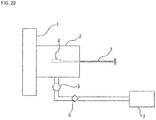
- Fig. 22 is a diagram schematically illustrating a main part of a scanning electron microscope described herein.
- This scanning electron microscope (SEM) 1 includes a preliminary exhaust chamber 2 capable of being introduced with a sample 4 to be mounted in a sample chamber in the microscope body, and an exhauster 7 deaerating the sample chamber and the preliminary exhaust chamber 2.
- SEM 1 a sample is set inside of the sample chamber to be observed, and a preliminary exhaust chamber 2 is provided between the sample chamber and the outside as a sample exchange chamber in order to maintain the sample chamber in high vacuum, and the sample 4 is taken in and out by a sample exchange bar 3.
- This preliminary exhaust chamber 2 is connected with the exhauster 7 such as a vacuum pump, a control valve 6 such as a needle valve is equipped in the exhaust pathway between the preliminary exhaust chamber 2 and the exhauster 7, and a vacuum gauge 5 such as a pirani vacuum gauge is equipped on the exhaust upstream side of the control valve 6.
- the exhauster 7 such as a vacuum pump
- a control valve 6 such as a needle valve is equipped in the exhaust pathway between the preliminary exhaust chamber 2 and the exhauster 7, and a vacuum gauge 5 such as a pirani vacuum gauge is equipped on the exhaust upstream side of the control valve 6.
- a mechanism in which the vacuum gauge 5 and the control valve 6 are combined, is provided in SEM 1, so that the speed of vacuum exhaust can be controlled until achieving the vacuum degree of the rotary pump region.
- This device (usable at different degrees of vacuum), in which exhaust is stepwisely performed, is preferably configured such that the sample chamber and the preliminary exhaust chamber 2 are large in size, a high functional vacuum pump is equipped so that the large chambers are effectively vacuumed, and the degree of vacuum can be instantly controlled.
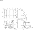
- Figs. 23(a) to 23(e) are diagrams schematically illustrating a main part of another scanning electron microscope described herein.
- Fig. 23(a) is a front view of the SEM main body and power source
- Fig. 23(b) is a side view thereof
- Fig. 23(c) is a side view of the state in which a glove box is detached
- Fig. 23(d) is a side view of the state in which a glove box is attached
- Fig. 23(e) is a perspective view illustrating the state in which an inert gas cylinder is attached to a glove box.
- the preliminary exhaust chamber 2 is equipped with a glove box 12. It is possible to perform work in a vacuum by equipping the preliminary exhaust chamber 2 with a glove box 12.
- the sample chamber 10 at the lower part of a microscope body 8 of SEM 1 attached with the power source 9 is provided with the glove box 12 alongside such that a sample folder 11 is accommodated in a housing 14 in the glove box 12.
- the glove box 12 has a work port 15, which is attached with a rubber glove or the like, and window part 14, through which the inside can be seen, so that work dealt with a sample is possible under vacuum. Moreover, a sample can be introduced into the sample chamber in the SEM 1 from the inside of the glove box 12 as a sample introducing part by the sample folder 11 without exposing the thin film covering the sample to atmospheric pressure. For example, plasma polymerized film can be formed in the glove box 12 connected to SEM 1.
- the glove box 12 enables a sample to be handled under vacuum, and, as described in Fig. 23(e) , it is also possible that the glove box 12 is equipped with the inert gas cylinder 16, which is capable of being introduced with an inert gas such as argon or nitrogen, and thus the inside of the glove box 12 is purged with an inert gas, and then used.
- the inert gas cylinder 16 which is capable of being introduced with an inert gas such as argon or nitrogen, and thus the inside of the glove box 12 is purged with an inert gas, and then used.
- This is suitable for plasma treatment and the like.
- the reaction can be controlled by filling the glove box with a specific gas such as nitrogen and argon.
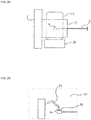
- Fig. 24 is a diagram schematically illustrating a main part of still another scanning electron microscope described herein.
- the preliminary exhaust chamber 2 is equipped with plasma irradiation device or electron irradiation device 18.
- sample chamber of SEM 1 may be equipped with this plasma irradiation device or electron irradiation device 18.
- the preliminary exhaust chamber 2 is equipped with a transparent bell jar 17.
- Plasma or an electron beam can be irradiated from the plasma irradiation device or electron irradiation device 18 via this transparent bell jar 17.
- the plasma irradiation device can be configured such that a handy type plasma irradiation device, of which the irradiation portion is held in hand, is additionally equipped in addition to a plasma irradiation device of the related art, which is used in ion etching and of which the
- the sample stub to be mounted with the sample 4 may have a function rotating three dimensionally so that the entire surface of the sample can be uniformly polymerized by the irradiation of an electron beam or plasma.
- design in which an electron beam or plasma can pass through the sample stub, can be applied so that the polymerization is performed to the rare face of the sample.
- a CCD camera recording work in the preliminary exhaust chamber 2 is equipped, and thus the situation of the sample 4 in a preliminary exhaust state and the situation of the plasma irradiation can be monitored.
- the irradiation time or the amperage of the plasma irradiation device or electron irradiation device 18 can be automatically or manually controlled by incorporating a device, by which plasma or an electron beam can be irradiated in various conditions, to the preliminary chamber 2.
- Fig. 25 is a diagram schematically illustrating a main part of yet another scanning electron microscope described herein.
- a sample chamber inside 19 is equipped with a three dimensional manipulator 21 capable of operating on the sample 4.
- the preliminary exhaust chamber 2 may be equipped with this three dimensional manipulator 21.
- This three dimensional manipulator 21 is used for the control (including reduction of picture blur at the time of observation and photographing) of the movement of the living biological sample.
- This three dimensional manipulator 21 can also be used in microvivisection, stimulation, and biological signal derivation.
- the sample chamber inside 19 can be equipped with the three dimensional manipulator 21 as a transfer mechanism for transferring a member used in the transfer of a sample, the microdissection of a sample, or physical or chemical stimulation.
- the detection position regulatory mechanism enables the secondary electron detector 22 to transfer in the SEM 1, and if necessary, brings the secondary electron detector 22 close to the sample 4 or into contact with the sample 4 at a special angle. Consequently, the detected secondary electron can be intensified.
- This detection position regulatory mechanism is suitable to be equipped with a high speed photography device.
- this detection position regulatory mechanism is a TV mode in which the scanning speed can increase and slow reproduction is possible, the area control of the detector and the control of working distance to the detector, and the like are possible, and the secondary electrons can be collected without waste.
- Software characterizing the movement by taking the finite difference of before and behind, and the like can also be applied as an interpolation technique.
- Fig. 27 is a diagram schematically illustrating a main part of further scanning electron microscope described herein.
- the sample chamber inside 19 is equipped with a high speed color camera 23 capable of acquiring color information of the sample 4.
- the color of the sample 4 is preserved as it is since the sample 4 can be observed as it is alive.
- the sample chamber inside 19 is equipped with a high speed color camera 23 so that the information such as colors can also be recorded, and thus the actual colors recorded can be applied to the image observed by SEM as pseudo colors.
- Fig. 28 is a diagram schematically illustrating a main part of further another embodiment of a scanning electron microscope described herein.
- the scanning electron microscope includes a temperature regulator 24 capable of regulating the temperature of the sample stub 20 of the sample chamber inside 19.
- a stage which can control the temperature of the sample stub 20 between -20°C to 100°C at the outside of the microscope body, and which is not affected by a magnetic field, can be equipped.
- a Peltier element and the like can be equipped as a device maintaining the temperature of the sample stub 20 at a constant value (for example, 37°C).
- the temperature of the sample 4, such as a biological sample, mounted on the sample stub 20 can be regulated by this temperature regulator 24.
- Fig. 29 is a diagram schematically illustrating a main part of still another scanning electron microscope described herein.
- the sample chamber inside 19 is equipped with various sensors 25.
- Examples of the sensor 25 may include an electrical sensor, a light sensor, a gas sensor, a water sensor, and a temperature sensor.
- a highly sensitive sensor capable of measuring at week light can be equipped.
- the information of the sample 4, such as a biological sample, mounted on the sample stub 20 can be acquired, and the monitoring or measurement of the response to the physical or chemical stimulation and the like, polymerization reaction, and the like can be performed.
- Fig. 30 is a diagram schematically illustrating a main part of a transmission electron microscope described herein
- Fig. 31 is a perspective view schematically illustrating the main part of Fig. 30 .
- Each of the both sides of a grid mesh 33 to be mounted with a sample has a polymerized film 32 formed by irradiating the composition for evaporation suppression with an electron beam or plasma.
- a sandwich-like sample folder for TEM has a C-ring 30 and O-ring 31, of which the lower place is mounted with the grid mesh 33 interposed with an upper polymerized film and a lower polymerized film 32.
- the polymerized film 32 can be sealed by, for example, vacuum grease and the O-ring.
- a transmission electron microscope can includes a preliminary exhaust chamber capable of being introduced with a sample to be mounted in a sample chamber in the microscope body, and an exhauster deaerating the sample chamber and the preliminary exhaust chamber in the same manner as the SEM of Fig. 22 .
- the sample chamber or the preliminary exhaust chamber is equipped with a plasma irradiation device or an electron beam irradiation device in the same manner as the SEM of Fig.
- the polymerized film 32 can be formed by applying the composition for evaporation suppression and irradiating plasma after modifying the TEM such that a plasma or electron beam polymerization can be performed in the preliminary exhaust chamber of the TEM.
- the irradiation diameter of plasma can be adjusted in a range of several nm to several tens cm, and thus the area of irradiation can be changed according to the size of a sample.
- dynamic analysis as it is alive can be performed even in a high vacuum by sealing a target cell and a culture solution in the sample folder by such a method. A sample bonded with colloidal gold can also be observed.
- a long time observation is possible by modifying a Scanning Transmission Electron Microscope (STEM) and reducing the dose of electron beam irradiated to a living sample introduced in the TEM.
- STEM Scanning Transmission Electron Microscope
- SEM observation was typically performed using a field emission-type scanning electron microscope (FESEM, S-4800 (Hitachi)) at an acceleration voltage of 5.0 kV.
- FESEM field emission-type scanning electron microscope
- S-4800 Hitachi
- the image data of SEM was directly transferred to a video recorder (Hi-band digital formatted video recorder, Pioneer, DVR-DT95).
- TEM observation was typically performed using JEM-1220 (JEOL) at an acceleration voltage of 120 kV.
- Plasma polymerization was typically performed by an ion sputtering device (JFC-1100, JEOL), in which the metallic target was disjointed, and plasma irradiation was performed in a vacuum level of about 1.0 Pa, at room temperature and 1.0 kV DC (8.0 mA) for 3 minutes.
- JFC-1100, JEOL ion sputtering device
- the metallic target was disjointed
- plasma irradiation was performed in a vacuum level of about 1.0 Pa, at room temperature and 1.0 kV DC (8.0 mA) for 3 minutes.
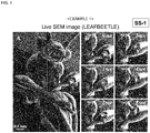
- a composition for evaporation suppression was prepared using a 0.1 % aqueous solution of sodium laurylbenzenesulfonate as an amphiphilic compound and 0.01 wt% of ethylenediamine nickel complex as a metal compound.
- a living leaf beetle was immersed in the composition for evaporation suppression for 1 minute, taken out therefrom, and the excess was wiped off, thereby covering the body surface of the leaf beetle with a thin film.
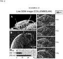
- a composition for evaporation suppression was prepared using a 0.1 % aqueous solution of sodium laurylbenzenesulfonate as an amphiphilic compound and 0.01 wt% of ethylenediamine nickel complex as a metal compound.
- a living collembolan was immersed in the composition for evaporation suppression for 1 minute, taken out therefrom, and the excess was wiped off, thereby covering the body surface of the collembolan with a thin film.
- the collembolan covered with a thin film was introduced in the sample chamber of a SEM, and videotaped ( Fig. 2 ). The situation that the collembolan was moving was observed even after the initiation of electron beam irradiation.
- the collembolan was alive even after taken out from the sample chamber after SEM observation.
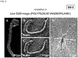
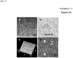
- a composition for evaporation suppression was prepared using a 10% aqueous solution of Tween 20 as an amphiphilic compound, and 1% (w/v) of trehalose and 0.1% (w/v) of pullulan as saccharides.
- a living larva of Chironomus yoshimatsui was immersed in the composition for evaporation suppression for 1 minute, taken out therefrom, and the excess was wiped off, thereby covering the body surface of the larva of Chironomus yoshimatsui with a thin film.
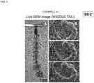
- a composition for evaporation suppression was prepared using a 10% aqueous solution of Tween 20 as an amphiphilic compound, and 1% (w/v) of trehalose and 0.1% (w/v) of pullulan as saccharides.
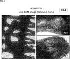
- a living larva of wiggle tail (Aedes albopictus) was immersed in the composition for evaporation suppression for 1 minute, taken out therefrom, and the excess was wiped off, thereby covering the body surface of the larva of wiggle tail with a thin film.
- the larva of wiggle tail was alive even after taken out from the sample chamber after SEM observation, and was metamorphosed into an imago.
- a composition for evaporation suppression was prepared using a 10% aqueous solution of Tween 20 as an amphiphilic compound, and 1% (w/v) of trehalose and 0.1% (w/v) of pullulan as saccharides.
- a living larva of wiggle tail was immersed in the composition for evaporation suppression for 1 minute, taken out therefrom, and the excess was wiped off, thereby covering the body surface of the larva of wiggle tail with a thin film.
- a composition for evaporation suppression was prepared using a 0.1 % aqueous solution of sodium laurylbenzenesulfonate as an amphiphilic compound and 0.01 wt% of ethylenediamine nickel complex as a metal compound.
- the ant was alive even after taken out from the sample chamber after SEM observation.
- a composition for evaporation suppression was prepared using a 0.1 % aqueous solution of sodium laurylbenzenesulfonate as an amphiphilic compound and 0.01 wt% of ethylenediamine nickel complex as a metal compound.
- a scale of living Oryzias latipes was immersed in the composition for evaporation suppression for 1 minute. Thereafter, the scale covered with the composition for evaporation suppression was introduced in the sample chamber of a TEM, and videotaped ( Fig. 7 ). The situation that the internal ultrastructure of the scale was changing was observed even after the initiation of electron beam irradiation.
- a composition for evaporation suppression was prepared using a 10% aqueous solution of Tween 20 as an amphiphilic compound, and 1% (w/v) of trehalose and 0.1% (w/v) of pullulan as saccharides.
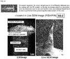
- a guppy was encapsulated in a microtube together with the breeding water, and only the caudal fin was put out from the microtube and the hole was sealed with dental wax. In this manner, only the caudal fin of the observation part was put out from the microtube, this leg part was coated with the composition for evaporation suppression, and then SEM observation thereof as it is alive was performed while preserving the air and water system in the microtube introduced with a guppy. It was possible to videotape the movement of the caudal fin even after the initiation of electron beam irradiation ( Fig. 8 ).
- a composition for evaporation suppression was prepared using a 10% aqueous solution of Tween 20 as an amphiphilic compound, and 1% (w/v) of trehalose and 0.1% (w/v) of pullulan as saccharides.
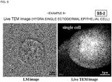
- An ectodermal epithelial cell of hydra was immersed in the composition for evaporation suppression for 1 minute. Thereafter, the ectodermal epithelial cell of hydra covered with the composition for evaporation suppression was introduced in the sample chamber of a TEM, and the ectodermal epithelial cell of hydra as it is alive was videotaped even after the initiation of electron beam irradiation ( Fig. 9 ).
- the left is the optical microscopic image and the right is the video image of TEM.
- the ectodermal epithelial cell of hydra was directly irradiated with an electron beam (120 kV) for 3 minutes under high vacuum after performing the treatment described above but without performing a pretreatment of the related art.
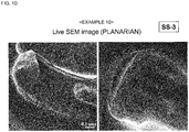
- Fats and oils were used as a composition for evaporation suppression.
- a living planarian was immersed in the composition for evaporation suppression (silicon oil) for 1 minute, taken out therefrom, and the excess was wiped off, thereby covering the body surface of the living planarian with a thin film.
- evaporation suppression silicon oil
- the living planarian covered with a thin film was introduced in the sample chamber of a SEM, and videotaped ( Fig. 10 ). The situation that the planarian was moving was observed even after the initiation of electron beam irradiation.
- planarian was alive even after taken out from the sample chamber after SEM observation.
- Tween 20 was used as an amphiphilic compound.
- Tween 20 of 50% (v/v) was dissolved in 100% ethanol, the resultant solution was spread on a glass plate using a spin coater (3000 rpm, 5s) (SC8001, Aiden), and then subjected to a plasma polymerization. The thin film after polymerization was released from the glass plate in ethanol.
- Fig. 11 (a) is an optical microscopic image of the independent polymerized film (Tween 20) formed by plasma irradiation
- Fig. 11 (b) is the chemical formula of Tween 20
- Fig. 11 (c) is an AMF image of the film surface
- Fig. 11 (d) is a TEM image of the cross section of the film.
- the distance between the arrows in Fig. 11 (d) is the polymerized film of Tween 20.
- a thin layer is formed on the surface (the part between the arrowheads) of the irradiation side.
- composition for evaporation suppression was prepared using a 1% aqueous solution of Tween 20 as an amphiphilic compound.
- a living larva of wiggle tail was immersed in the composition for evaporation suppression for 1 minute, taken out therefrom, and the excess was wiped off, thereby covering the body surface of the living larva of wiggle tail with a thin film.
- Figs. 12(a) to 12(o) are SEM images of related art and novel SEM images of a sample coated with a plasma irradiated film (Tween 20).
- Fig. 12(a) is an optical microscopic image of wiggle tail
- Figs. 12(b) to 12(d) are SEM images of the related art
- Figs. 12(f) to 12(n) are individuals irradiated with plasma (without coating of Tween 20 (f to i) and with coating of Tween 20 (k to n))
- Figs. 12(e), 12(j), and 12(o) are TEM images of the cross section of sample.
- a living wiggle tail (a, time 0) was not irradiated with an electron beam, and a living wiggle tail (b to d, time 30) was irradiated with an electron beam for 30 minutes under high vacuum in a SEM.
- the arrowhead indicates the area of electrostatic charging.
- a living wiggle tail covered with 1% Tween 20 was irradiated with plasma for 3 minutes (f, time 0), and then observed by SEM for 30 minutes (g to i).
- a living wiggle tail was irradiated with an electron beam in a SEM of the related art (k is an optical microscopic image), and then observed (l to n).
- Figs 12 are TEM images of the cross section of sample, and the layer between the arrowheads is a polymerized film formed by a plasma treatment.
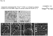
- Triton TM X-100 was used as an amphiphilic compound. Triton TM X-100 of 1% (v/v) was dissolved in distilled water, the resultant solution was spread on a glass plate using a spin coater, and plasma polymerized, thereby obtaining an independent thin film in the same manner as in Example 11.
- Fig. 13(a) is an optical microscopic image of the independent polymerized film (Triton TM X-100) formed by plasma irradiation and Fig. 13(b) is the chemical formula of Triton TM X-100.
- composition for evaporation suppression was prepared using a 1% aqueous solution of Triton TM X-100 as an amphiphilic compound.
- a living larva of wiggle tail was immersed in the composition for evaporation suppression for 1 minute, taken out therefrom, and the excess was wiped off, thereby covering the body surface of the living larva of wiggle tail with a thin film.
- Fig. 13(c) indicates the situation at 0 minute
- Fig. 13 (d) indicates the situation at 30 minutes
- the inside of the square of Fig. 13 (d) was enlarged ( Fig. 13 (e) ) and further enlarged ( Fig. 13 (f) ).
- the situation that the larva of wiggle tail was moving was observed even after the initiation of electron beam irradiation.
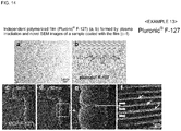
- Pluronic (R) F-127 was used as an amphiphilic compound.
- Pluronic (R) F-127 of 1% (v/v) was dissolved in distilled water, the resultant solution was spread on a glass plate using a spin coater, and plasma polymerized, thereby obtaining an independent thin film in the same manner as in Example 11.
- Fig. 14(a) is an optical microscopic image of the independent polymerized film (Triton TM X-100) formed by plasma irradiation and
- Fig. 14(b) is the chemical formula of pluronic (R) F-127.
- composition for evaporation suppression was prepared using a 1% aqueous solution of pluronic (R) F-127as an amphiphilic compound.
- a living larva of wiggle tail was immersed in the composition for evaporation suppression for 1 minute, taken out therefrom, and the excess was wiped off, thereby covering the body surface of the living larva of wiggle tail with a thin film.
- Fig. 14(c) indicates the situation at 0 minute
- Fig. 14 (d) indicates the situation at 30 minutes
- the inside of the square of Fig. 14 (d) was enlarged ( Fig. 14(e) ) and further enlarged ( Fig. 14(f) ).
- the situation that the larva of wiggle tail was moving was observed even after the initiation of electron beam irradiation.
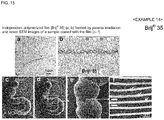
- Brij (R) 35 was used as an amphiphilic compound.
- Brij (R) 35 of 1% (v/v) was dissolved in distilled water, the resultant solution was spread on a glass plate using a spin coater, and plasma polymerized, thereby obtaining an independent thin film in the same manner as in Example 11.
- Fig. 15(a) is an optical microscopic image of the independent polymerized film (Brij (R) 35) formed by plasma irradiation and Fig. 15(b) is the chemical formula of Brij (R) 35.
- composition for evaporation suppression was prepared using a 1% aqueous solution of Brij (R) 35 as an amphiphilic compound.
- a living larva of wiggle tail was immersed in the composition for evaporation suppression for 1 minute, taken out therefrom, and the excess was wiped off, thereby covering the body surface of the living larva of wiggle tail with a thin film.
- Fig. 15(c) indicates the situation at 0 minute
- Fig. 15 (d) indicates the situation at 30 minutes
- the inside of the square of Fig. 15 (d) was enlarged ( Fig. 15(e) ) and further enlarged ( Fig. 15(f) ).
- the situation that the larva of wiggle tail was moving was observed even after the initiation of electron beam irradiation.
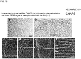
- CHAPS was used as an amphiphilic compound. CHAPS of 1% (v/v) was dissolved in distilled water, the resultant solution was spread on a glass plate using a spin coater, and plasma polymerized, thereby obtaining an independent thin film in the same manner as in Example 11.
- Fig. 16(a) is an optical microscopic image of the independent polymerized film (CHAPS) formed by plasma irradiation and Fig. 16(b) is the chemical formula of CHAPS.
- composition for evaporation suppression was prepared using a 1% aqueous solution of CHAPS as an amphiphilic compound.
- a living larva of wiggle tail was immersed in the composition for evaporation suppression for 1 minute, taken out therefrom, and the excess was wiped off, thereby covering the body surface of the living larva of wiggle tail with a thin film.
- Fig. 16(c) indicates the situation at 0 minute
- Fig. 16 (d) indicates the situation at 30 minutes
- the inside of the square of Fig. 16 (d) was enlarged ( Fig. 16(e) ) and further enlarged ( Fig. 16(f) ).
- the situation that the larva of wiggle tail was moving was observed even after the initiation of electron beam irradiation.
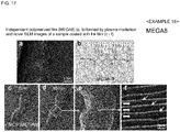
- MEGA8 was used as an amphiphilic compound.
- MEGA8 of 1% (v/v) was dissolved in distilled water, the resultant solution was spread on a glass plate using a spin coater, and plasma polymerized, thereby obtaining an independent thin film in the same manner as in Example 11.
- Fig. 17(a) is an optical microscopic image of the independent polymerized film (MEGA8) formed by plasma irradiation and
- Fig. 17(b) is the chemical formula of MEGA8.
- composition for evaporation suppression was prepared using a 1% aqueous solution of MEGA8 as an amphiphilic compound.
- a living larva of wiggle tail was immersed in the composition for evaporation suppression for 1 minute, taken out therefrom, and the excess was wiped off, thereby covering the body surface of the living larva of wiggle tail with a thin film.
- Fig. 17(c) indicates the situation at 0 minute
- Fig. 17(d) indicates the situation at 30 minutes
- the inside of the square of Fig. 17(d) was enlarged ( Fig. 17(e) ) and further enlarged ( Fig. 17(f) ).
- the situation that the larva of wiggle tail was moving was observed even after the initiation of electron beam irradiation.
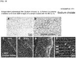
- Sodium cholate was used as an amphiphilic compound. Sodium cholate of 1% (v/v) was dissolved in distilled water, the resultant solution was spread on a glass plate using a spin coater, and plasma polymerized, thereby obtaining an independent thin film in the same manner as in Example 11.
- Fig. 18(a) is an optical microscopic image of the independent polymerized film (sodium cholate) formed by plasma irradiation and Fig. 18(b) is the chemical formula of sodium cholate.
- composition for evaporation suppression was prepared using a 1% aqueous solution of sodium cholate as an amphiphilic compound.
- a living larva of wiggle tail was immersed in the composition for evaporation suppression for 1 minute, taken out therefrom, and the excess was wiped off, thereby covering the body surface of the living larva of wiggle tail with a thin film.
- Fig. 18(c) indicates the situation at 0 minute
- Fig. 18 (d) indicates the situation at 30 minutes
- the inside of the square of Fig. 18 (d) was enlarged ( Fig. 18(e) ) and further enlarged ( Fig. 18(f) ).
- the situation that the larva of wiggle tail was moving was observed even after the initiation of electron beam irradiation.
- n-Dodecyl- ⁇ -D-maltoside was used as an amphiphilic compound. n-Dodecyl- ⁇ -D-maltoside of 1 % (v/v) was dissolved in distilled water, the resultant solution was spread on a glass plate using a spin coater, and plasma polymerized, thereby obtaining an independent thin film in the same manner as in Example 11.
- Fig. 19(a) is an optical microscopic image of the independent polymerized film (n-dodecyl- ⁇ -D-maltoside) formed by plasma irradiation and Fig. 19(b) is the chemical formula of n-dodecyl- ⁇ -D-maltoside.
- composition for evaporation suppression was prepared using a 1% aqueous solution of n-dodecyl- ⁇ -D-maltoside as an amphiphilic compound.
- a living larva of wiggle tail was immersed in the composition for evaporation suppression for 1 minute, taken out therefrom, and the excess was wiped off, thereby covering the body surface of the living larva of wiggle tail with a thin film.
- Fig. 19(c) indicates the situation at 0 minute
- Fig. 19 (d) indicates the situation at 30 minutes
- the inside of the square of Fig. 19 (d) was enlarged ( Fig. 19(e) ) and further enlarged ( Fig. 19(f) ).
- the situation that the larva of wiggle tail was moving was observed even after the initiation of electron beam irradiation.
- n-Octyl- ⁇ -D-glucoside was used as an amphiphilic compound. n-Octyl- ⁇ -D-glucoside of 1 % (v/v) was dissolved in distilled water, the resultant solution was spread on a glass plate using a spin coater, and plasma polymerized, thereby obtaining an independent thin film in the same manner as in Example 11.
- Fig. 20(a) is an optical microscopic image of the independent polymerized film (n-octyl- ⁇ -D-glucoside) formed by plasma irradiation and Fig. 20(b) is the chemical formula of n-octyl- ⁇ -D-glucoside.
- composition for evaporation suppression was prepared using a 1% aqueous solution of n-octyl- ⁇ -D-glucoside as an amphiphilic compound.
- a living larva of wiggle tail was immersed in the composition for evaporation suppression for 1 minute, taken out therefrom, and the excess was wiped off, thereby covering the body surface of the living larva of wiggle tail with a thin film.
- Fig. 20(c) indicates the situation at 0 minute
- Fig. 20 (d) indicates the situation at 30 minutes
- the inside of the square of Fig. 20 (d) was enlarged ( Fig. 20(e) ) and further enlarged ( Fig. 20(f) ).
- the situation that the larva of wiggle tail was moving was observed even after the initiation of electron beam irradiation.
- 1,3-Diallylimidazolium bromide was used as an ionic liquid. 1,3-Diallylimidazolium bromide of 1% (v/v) was dissolved in distilled water, the resultant solution was spread on a glass plate using a spin coater, and plasma polymerized, thereby obtaining an independent thin film in the same manner as in Example 11.
- Fig. 20(a) is an optical microscopic image of the independent polymerized film (1,3-diallylimidazolium bromide) formed by plasma irradiation and Fig. 20(b) is the chemical formula of 1,3-diallylimidazolium bromide.
- composition for evaporation suppression was prepared using a 1% aqueous solution of 1,3-diallylimidazolium bromide as an ionic liquid.
- a living larva of wiggle tail was immersed in the composition for evaporation suppression for 1 minute, taken out therefrom, and the excess was wiped off, thereby covering the body surface of the living larva of wiggle tail with a thin film.
- Fig. 21 (c) indicates the situation at 0 minute
- Fig. 21 (d) indicates the situation at 30 minutes
- the inside of the square of Fig. 21 (d) was enlarged ( Fig. 21 (e) ) and further enlarged ( Fig. 21 (f) ).
- the situation that the larva of wiggle tail was moving was observed even after the initiation of electron beam irradiation.
Landscapes
- Chemical & Material Sciences (AREA)
- Analytical Chemistry (AREA)
- Physics & Mathematics (AREA)
- Health & Medical Sciences (AREA)
- Life Sciences & Earth Sciences (AREA)
- Biochemistry (AREA)
- General Health & Medical Sciences (AREA)
- General Physics & Mathematics (AREA)
- Immunology (AREA)
- Pathology (AREA)
- Analysing Materials By The Use Of Radiation (AREA)
- Sampling And Sample Adjustment (AREA)
Applications Claiming Priority (3)
| Application Number | Priority Date | Filing Date | Title |
|---|---|---|---|
| JP2011197685 | 2011-09-09 | ||
| JP2012044383 | 2012-02-29 | ||
| PCT/JP2012/072982 WO2013035866A1 (ja) | 2011-09-09 | 2012-09-07 | 生物試料をそのままの姿で観察するための電子顕微鏡による観察方法とそれに用いられる真空下での蒸発抑制用組成物、走査型電子顕微鏡および透過型電子顕微鏡 |
Publications (3)
| Publication Number | Publication Date |
|---|---|
| EP2755225A1 EP2755225A1 (en) | 2014-07-16 |
| EP2755225A4 EP2755225A4 (en) | 2015-08-05 |
| EP2755225B1 true EP2755225B1 (en) | 2017-05-10 |
Family
ID=47832305
Family Applications (1)
| Application Number | Title | Priority Date | Filing Date |
|---|---|---|---|
| EP12829935.1A Active EP2755225B1 (en) | 2011-09-09 | 2012-09-07 | Electron-microscopic examination method for examining a living biological sample |
Country Status (7)
| Country | Link |
|---|---|
| US (1) | US9557253B2 (cg-RX-API-DMAC7.html) |
| EP (1) | EP2755225B1 (cg-RX-API-DMAC7.html) |
| JP (1) | JP6055766B2 (cg-RX-API-DMAC7.html) |
| KR (1) | KR101650054B1 (cg-RX-API-DMAC7.html) |
| CN (1) | CN103843106B (cg-RX-API-DMAC7.html) |
| IN (1) | IN2014DN01848A (cg-RX-API-DMAC7.html) |
| WO (1) | WO2013035866A1 (cg-RX-API-DMAC7.html) |
Families Citing this family (28)
| Publication number | Priority date | Publication date | Assignee | Title |
|---|---|---|---|---|
| JP5922908B2 (ja) * | 2011-10-27 | 2016-05-24 | 富士フイルム株式会社 | 硬化物の製造方法および硬化物 |
| JP6452630B2 (ja) * | 2014-01-29 | 2019-01-16 | 国立研究開発法人科学技術振興機構 | 含水状態の生物試料の電子顕微鏡観察用保護剤、電子顕微鏡観察用キット、電子顕微鏡による観察、診断、評価、定量の方法並びに試料台 |
| JP6496184B2 (ja) * | 2014-06-27 | 2019-04-03 | 日本電子株式会社 | 試料導入方法、試料ステージ、および荷電粒子線装置 |
| KR101792832B1 (ko) * | 2014-10-29 | 2017-11-20 | 충남대학교산학협력단 | 기-액 계면 플라즈마 중합에 의한 고분자 박막의 제조방법 및 이에 의해 제조된 고분자 박막 |
| JP6569151B2 (ja) * | 2015-02-25 | 2019-09-04 | 学校法人日本大学 | イオン液体を用いた透過型電子顕微鏡による錯体の観察方法及び観察用試料 |
| CN104908063A (zh) * | 2015-06-24 | 2015-09-16 | 中山安荞生物科技有限公司 | 一种真空手套箱 |
| DE102016202379A1 (de) * | 2016-02-17 | 2017-08-17 | Carl Zeiss Microscopy Gmbh | Verfahren zur Präparation von Objekten für Untersuchungen mit geladenen Teilchenstrahlen |
| TWI594288B (zh) * | 2016-03-14 | 2017-08-01 | 台灣電鏡儀器股份有限公司 | 電子顯微鏡 |
| EP3509651B1 (en) | 2016-09-06 | 2022-12-28 | Miromatrix Medical Inc. | Use of resected liver serum for whole liver engineering |
| JP2018078028A (ja) * | 2016-11-09 | 2018-05-17 | 株式会社メルビル | 試料ホルダー |
| CN107860783B (zh) * | 2017-10-23 | 2019-09-24 | 中国科学院化学研究所 | Xps进样装置 |
| JP7001425B2 (ja) * | 2017-10-26 | 2022-01-19 | シンフォニアテクノロジー株式会社 | マウンタ用エア制御装置 |
| JP7492741B2 (ja) * | 2018-01-10 | 2024-05-30 | ユニバーシティ・オブ・カンザス | 電子顕微鏡の導電性固定 |
| CN110243640B (zh) * | 2018-03-08 | 2022-01-25 | 中国科学院海洋研究所 | 深海有孔虫的内腔磨片快速制备方法 |
| CN108802080A (zh) * | 2018-08-16 | 2018-11-13 | 扬州大学 | 一种玉米成熟种子中胚乳淀粉生长环的原位观察方法 |
| WO2020191374A1 (en) * | 2019-03-21 | 2020-09-24 | Miromatrix Medical Inc. | Improved decellularization of isolated organs |
| CN109916942B (zh) * | 2019-04-18 | 2021-09-21 | 攀钢集团攀枝花钢铁研究院有限公司 | 捕收剂的电子显微镜表征方法 |
| CN110441084A (zh) * | 2019-09-04 | 2019-11-12 | 海南省农业科学院热带果树研究所 | 一种菠萝蜜果肉的冰冻切片方法 |
| WO2021070338A1 (ja) * | 2019-10-10 | 2021-04-15 | 株式会社日立ハイテク | 荷電粒子線装置 |
| JP7142404B2 (ja) | 2020-06-16 | 2022-09-27 | 学校法人中部大学 | 走査型電子顕微鏡を用いた観察方法、及びそのための試料ホルダ |
| CN111855507A (zh) * | 2020-07-17 | 2020-10-30 | 北方民族大学 | 一种空气颗粒物的检测装置及检测方法 |
| JP7665174B2 (ja) * | 2020-09-26 | 2025-04-21 | NanoSuit株式会社 | 食品のコーティング方法及びコーティング装置 |
| CN112611775B (zh) * | 2020-12-16 | 2023-08-11 | 聚束科技(北京)有限公司 | 一种用于观察生物组织的方法及电子显微镜 |
| KR102740532B1 (ko) | 2021-11-03 | 2024-12-16 | 대한민국 | 스마트 온실 로봇을 위한 농약 자동 공급 장치 및 그 동작 방법 |
| JP7685158B2 (ja) * | 2022-01-28 | 2025-05-30 | 国立大学法人千葉大学 | 被覆装置、被覆方法 |
| CN114773216A (zh) * | 2022-03-24 | 2022-07-22 | 天津大学 | 一种l-亮氨酸球形晶体及其制备方法和应用 |
| CN116396809A (zh) * | 2023-03-30 | 2023-07-07 | 橙的(福建)卫生用品有限责任公司 | 一种厨房湿巾的制备方法 |
| CN118330207B (zh) * | 2024-06-12 | 2024-08-09 | 成都海默云因医学检验实验室有限公司 | 一种改善固定细胞免疫荧光法中荧光背景的固定剂及其固定细胞的方法 |
Family Cites Families (25)
| Publication number | Priority date | Publication date | Assignee | Title |
|---|---|---|---|---|
| JPS57147857A (en) * | 1981-03-06 | 1982-09-11 | Koichi Kanetani | Sample observation through scanning electron microscope |
| JPS612250A (ja) | 1984-06-15 | 1986-01-08 | Hitachi Ltd | 走査電子顕微鏡およびその類似装置における試料導入装置 |
| JPS6188442A (ja) * | 1984-10-05 | 1986-05-06 | Hitachi Ltd | イオンビ−ム照射装置 |
| JPS6176676U (cg-RX-API-DMAC7.html) * | 1984-10-25 | 1986-05-23 | ||
| JPS6378116A (ja) | 1986-09-22 | 1988-04-08 | Mitsubishi Electric Corp | 広帯域光学撮像装置 |
| JPH01197626A (ja) * | 1988-02-02 | 1989-08-09 | Ushio Inc | 封入検鏡試料の作製方法 |
| JPH0621165Y2 (ja) * | 1988-06-13 | 1994-06-01 | 株式会社エイコー・エンジニアリング | 電子顕微鏡用試料凍結乾燥装置 |
| JPH04106853A (ja) * | 1990-08-28 | 1992-04-08 | Jeol Ltd | 走査電子顕微鏡 |
| JPH078116A (ja) | 1993-06-29 | 1995-01-13 | Kubota Corp | 育苗箱構造 |
| JPH1012173A (ja) * | 1996-06-20 | 1998-01-16 | Hitachi Ltd | 電子顕微鏡の汚染防止システム |
| JPH10134751A (ja) * | 1996-10-29 | 1998-05-22 | Nikon Corp | 環境制御型の走査型電子顕微鏡 |
| JP3019038B2 (ja) * | 1997-09-17 | 2000-03-13 | 日本電気株式会社 | 半導体装置 |
| JP2001153760A (ja) * | 1999-11-30 | 2001-06-08 | Shimadzu Corp | 搬送用試料容器 |
| JP2003203595A (ja) * | 2002-01-08 | 2003-07-18 | Jeol Ltd | 電子顕微鏡 |
| JP3946602B2 (ja) * | 2002-09-03 | 2007-07-18 | 株式会社日立ハイテクノロジーズ | 荷電粒子線装置 |
| JP2005026530A (ja) * | 2003-07-04 | 2005-01-27 | Jeol Ltd | 試料ホルダ移動機構及び真空装置並びに荷電粒子ビーム装置 |
| DE10344492B4 (de) * | 2003-09-24 | 2006-09-07 | Carl Zeiss Nts Gmbh | Teilchenstrahlgerät |
| JP2005285485A (ja) * | 2004-03-29 | 2005-10-13 | Toudai Tlo Ltd | プラズマ発生装置及び低真空走査電子顕微鏡 |
| JP4004490B2 (ja) * | 2004-07-22 | 2007-11-07 | 株式会社トプコン | 走査型電子顕微鏡装置 |
| EP3078962B1 (en) | 2006-01-20 | 2018-06-27 | Hitachi High-Technologies Corporation | Liquid medium for preventing charge-up in electron microscope and method of observing sample using the same |
| JP5226378B2 (ja) | 2008-04-28 | 2013-07-03 | 株式会社日立ハイテクノロジーズ | 透過型電子顕微鏡、及び試料観察方法 |
| JP2010002300A (ja) * | 2008-06-20 | 2010-01-07 | Jeol Ltd | 試料保持体、試料検査装置及び試料検査方法 |
| JP2010025656A (ja) | 2008-07-17 | 2010-02-04 | Jeol Ltd | イオン液体を用いた試料の処理方法及び処理システム |
| JP4799690B2 (ja) * | 2009-12-01 | 2011-10-26 | 国立大学法人北海道大学 | 電子顕微鏡による試料観察用の液状媒体とそれを用いた電子顕微鏡による試料観察方法 |
| JP5422416B2 (ja) * | 2010-01-28 | 2014-02-19 | 株式会社日立製作所 | 試料搬送装置 |
-
2012
- 2012-09-07 IN IN1848DEN2014 patent/IN2014DN01848A/en unknown
- 2012-09-07 CN CN201280044046.2A patent/CN103843106B/zh active Active
- 2012-09-07 KR KR1020147006126A patent/KR101650054B1/ko active Active
- 2012-09-07 WO PCT/JP2012/072982 patent/WO2013035866A1/ja not_active Ceased
- 2012-09-07 EP EP12829935.1A patent/EP2755225B1/en active Active
- 2012-09-07 US US14/343,537 patent/US9557253B2/en active Active
- 2012-09-07 JP JP2013532684A patent/JP6055766B2/ja active Active
Also Published As
| Publication number | Publication date |
|---|---|
| IN2014DN01848A (cg-RX-API-DMAC7.html) | 2015-05-15 |
| JPWO2013035866A1 (ja) | 2015-03-23 |
| US20140227734A1 (en) | 2014-08-14 |
| WO2013035866A1 (ja) | 2013-03-14 |
| JP6055766B2 (ja) | 2016-12-27 |
| KR101650054B1 (ko) | 2016-08-22 |
| US9557253B2 (en) | 2017-01-31 |
| EP2755225A4 (en) | 2015-08-05 |
| CN103843106A (zh) | 2014-06-04 |
| KR20140074287A (ko) | 2014-06-17 |
| EP2755225A1 (en) | 2014-07-16 |
| CN103843106B (zh) | 2016-12-07 |
Similar Documents
| Publication | Publication Date | Title |
|---|---|---|
| EP2755225B1 (en) | Electron-microscopic examination method for examining a living biological sample | |
| EP3101407B1 (en) | Kit and method for electron microscope observation | |
| Wei et al. | High-resolution three-dimensional reconstruction of a whole yeast cell using focused-ion beam scanning electron microscopy | |
| Palmer et al. | A cylindrical specimen holder for electron cryo-tomography | |
| Breen et al. | Correlating atom probe crystallographic measurements with transmission Kikuchi diffraction data | |
| Saghi et al. | Compressed sensing electron tomography of needle-shaped biological specimens–Potential for improved reconstruction fidelity with reduced dose | |
| US20140312226A1 (en) | Charged-particle microscope providing depth-resolved imagery | |
| Guesdon et al. | Single versus dual-axis cryo-electron tomography of microtubules assembled in vitro: limits and perspectives | |
| Tihlaříková et al. | In situ study of live specimens in an environmental scanning electron microscope | |
| JP2017201289A (ja) | 電子顕微鏡によるナノ粒子の直接的な同定・定量のための検出キットおよび方法 | |
| JP7591057B2 (ja) | 高角度液体電子断層撮影のためのデバイスおよび方法 | |
| de Jonge et al. | Resolution in liquid cell experiments | |
| Watkins et al. | Robustness of time-resolved measurement to unknown and variable beam current in particle beam microscopy | |
| EP2537174A1 (en) | Image processing method for mass spectrum image, program, and apparatus | |
| Causse et al. | Characterization of complex micellar systems by Scattering techniques (SAXS and SANS) and wet-scanning transmission electron microscopy (wet-STEM) | |
| Tanji et al. | Investigation of the cosmetic ingredient distribution in the stratum corneum using NanoSIMS imaging | |
| Gorman et al. | Imaging the distributions of lipids and proteins in the plasma membrane with high-resolution secondary ion mass spectrometry | |
| Woods et al. | Exploring the potential for scanning electron microscopy/focused ion beam-based diffraction for screening cryo-transmission electron microscopy samples | |
| De Jonge | Introduction to special issue on electron microscopy of specimens in liquid | |
| Ogura | Direct observation of the inner structure of unstained atmospheric cells by low-energy electrons | |
| John Mardinly | Electron Tomography and Three-Dimensional Aspects of Transmission Electron Microscopy | |
| Liu | ‘Tri-3D’electron microscopy tomography by FIB, SEM and TEM: Application to polymer nanocomposites | |
| Deitz et al. | Site-Specific TEM Specimen Preparation of Samples with Sub-Surface Features | |
| Dluhoš et al. | Ultra-Fast Three Dimensional Microanalysis Using the Scanning Electron Microscope Equipped with Xenon Plasma Focused Ion Beam | |
| Jalanti | 14 Scanning Electron Microscopy: A Powerful Tool for Imaging Freeze-Dried Material |
Legal Events
| Date | Code | Title | Description |
|---|---|---|---|
| PUAI | Public reference made under article 153(3) epc to a published international application that has entered the european phase |
Free format text: ORIGINAL CODE: 0009012 |
|
| 17P | Request for examination filed |
Effective date: 20140407 |
|
| AK | Designated contracting states |
Kind code of ref document: A1 Designated state(s): AL AT BE BG CH CY CZ DE DK EE ES FI FR GB GR HR HU IE IS IT LI LT LU LV MC MK MT NL NO PL PT RO RS SE SI SK SM TR |
|
| DAX | Request for extension of the european patent (deleted) | ||
| RIC1 | Information provided on ipc code assigned before grant |
Ipc: G01N 1/28 20060101ALI20150518BHEP Ipc: H01J 37/18 20060101ALI20150518BHEP Ipc: G01N 23/225 20060101ALI20150518BHEP Ipc: H01J 37/20 20060101AFI20150518BHEP Ipc: G01N 23/04 20060101ALI20150518BHEP |
|
| RA4 | Supplementary search report drawn up and despatched (corrected) |
Effective date: 20150706 |
|
| RIC1 | Information provided on ipc code assigned before grant |
Ipc: G01N 1/28 20060101ALI20150630BHEP Ipc: H01J 37/20 20060101AFI20150630BHEP Ipc: G01N 23/225 20060101ALI20150630BHEP Ipc: H01J 37/18 20060101ALI20150630BHEP Ipc: G01N 23/04 20060101ALI20150630BHEP |
|
| 17Q | First examination report despatched |
Effective date: 20160229 |
|
| STAA | Information on the status of an ep patent application or granted ep patent |
Free format text: STATUS: EXAMINATION IS IN PROGRESS |
|
| GRAP | Despatch of communication of intention to grant a patent |
Free format text: ORIGINAL CODE: EPIDOSNIGR1 |
|
| STAA | Information on the status of an ep patent application or granted ep patent |
Free format text: STATUS: GRANT OF PATENT IS INTENDED |
|
| INTG | Intention to grant announced |
Effective date: 20161223 |
|
| GRAS | Grant fee paid |
Free format text: ORIGINAL CODE: EPIDOSNIGR3 |
|
| GRAA | (expected) grant |
Free format text: ORIGINAL CODE: 0009210 |
|
| STAA | Information on the status of an ep patent application or granted ep patent |
Free format text: STATUS: THE PATENT HAS BEEN GRANTED |
|
| AK | Designated contracting states |
Kind code of ref document: B1 Designated state(s): AL AT BE BG CH CY CZ DE DK EE ES FI FR GB GR HR HU IE IS IT LI LT LU LV MC MK MT NL NO PL PT RO RS SE SI SK SM TR |
|
| REG | Reference to a national code |
Ref country code: GB Ref legal event code: FG4D |
|
| REG | Reference to a national code |
Ref country code: AT Ref legal event code: REF Ref document number: 893135 Country of ref document: AT Kind code of ref document: T Effective date: 20170515 Ref country code: CH Ref legal event code: EP |
|
| REG | Reference to a national code |
Ref country code: IE Ref legal event code: FG4D |
|
| REG | Reference to a national code |
Ref country code: DE Ref legal event code: R096 Ref document number: 602012032365 Country of ref document: DE |
|
| REG | Reference to a national code |
Ref country code: NL Ref legal event code: FP |
|
| REG | Reference to a national code |
Ref country code: LT Ref legal event code: MG4D |
|
| REG | Reference to a national code |
Ref country code: FR Ref legal event code: PLFP Year of fee payment: 6 |
|
| REG | Reference to a national code |
Ref country code: AT Ref legal event code: MK05 Ref document number: 893135 Country of ref document: AT Kind code of ref document: T Effective date: 20170510 |
|
| PG25 | Lapsed in a contracting state [announced via postgrant information from national office to epo] |
Ref country code: GR Free format text: LAPSE BECAUSE OF FAILURE TO SUBMIT A TRANSLATION OF THE DESCRIPTION OR TO PAY THE FEE WITHIN THE PRESCRIBED TIME-LIMIT Effective date: 20170811 Ref country code: FI Free format text: LAPSE BECAUSE OF FAILURE TO SUBMIT A TRANSLATION OF THE DESCRIPTION OR TO PAY THE FEE WITHIN THE PRESCRIBED TIME-LIMIT Effective date: 20170510 Ref country code: HR Free format text: LAPSE BECAUSE OF FAILURE TO SUBMIT A TRANSLATION OF THE DESCRIPTION OR TO PAY THE FEE WITHIN THE PRESCRIBED TIME-LIMIT Effective date: 20170510 Ref country code: LT Free format text: LAPSE BECAUSE OF FAILURE TO SUBMIT A TRANSLATION OF THE DESCRIPTION OR TO PAY THE FEE WITHIN THE PRESCRIBED TIME-LIMIT Effective date: 20170510 Ref country code: ES Free format text: LAPSE BECAUSE OF FAILURE TO SUBMIT A TRANSLATION OF THE DESCRIPTION OR TO PAY THE FEE WITHIN THE PRESCRIBED TIME-LIMIT Effective date: 20170510 Ref country code: AT Free format text: LAPSE BECAUSE OF FAILURE TO SUBMIT A TRANSLATION OF THE DESCRIPTION OR TO PAY THE FEE WITHIN THE PRESCRIBED TIME-LIMIT Effective date: 20170510 Ref country code: NO Free format text: LAPSE BECAUSE OF FAILURE TO SUBMIT A TRANSLATION OF THE DESCRIPTION OR TO PAY THE FEE WITHIN THE PRESCRIBED TIME-LIMIT Effective date: 20170810 |
|
| PG25 | Lapsed in a contracting state [announced via postgrant information from national office to epo] |
Ref country code: PL Free format text: LAPSE BECAUSE OF FAILURE TO SUBMIT A TRANSLATION OF THE DESCRIPTION OR TO PAY THE FEE WITHIN THE PRESCRIBED TIME-LIMIT Effective date: 20170510 Ref country code: BG Free format text: LAPSE BECAUSE OF FAILURE TO SUBMIT A TRANSLATION OF THE DESCRIPTION OR TO PAY THE FEE WITHIN THE PRESCRIBED TIME-LIMIT Effective date: 20170810 Ref country code: IS Free format text: LAPSE BECAUSE OF FAILURE TO SUBMIT A TRANSLATION OF THE DESCRIPTION OR TO PAY THE FEE WITHIN THE PRESCRIBED TIME-LIMIT Effective date: 20170910 Ref country code: RS Free format text: LAPSE BECAUSE OF FAILURE TO SUBMIT A TRANSLATION OF THE DESCRIPTION OR TO PAY THE FEE WITHIN THE PRESCRIBED TIME-LIMIT Effective date: 20170510 Ref country code: SE Free format text: LAPSE BECAUSE OF FAILURE TO SUBMIT A TRANSLATION OF THE DESCRIPTION OR TO PAY THE FEE WITHIN THE PRESCRIBED TIME-LIMIT Effective date: 20170510 Ref country code: LV Free format text: LAPSE BECAUSE OF FAILURE TO SUBMIT A TRANSLATION OF THE DESCRIPTION OR TO PAY THE FEE WITHIN THE PRESCRIBED TIME-LIMIT Effective date: 20170510 |
|
| PG25 | Lapsed in a contracting state [announced via postgrant information from national office to epo] |
Ref country code: DK Free format text: LAPSE BECAUSE OF FAILURE TO SUBMIT A TRANSLATION OF THE DESCRIPTION OR TO PAY THE FEE WITHIN THE PRESCRIBED TIME-LIMIT Effective date: 20170510 Ref country code: SK Free format text: LAPSE BECAUSE OF FAILURE TO SUBMIT A TRANSLATION OF THE DESCRIPTION OR TO PAY THE FEE WITHIN THE PRESCRIBED TIME-LIMIT Effective date: 20170510 Ref country code: RO Free format text: LAPSE BECAUSE OF FAILURE TO SUBMIT A TRANSLATION OF THE DESCRIPTION OR TO PAY THE FEE WITHIN THE PRESCRIBED TIME-LIMIT Effective date: 20170510 Ref country code: EE Free format text: LAPSE BECAUSE OF FAILURE TO SUBMIT A TRANSLATION OF THE DESCRIPTION OR TO PAY THE FEE WITHIN THE PRESCRIBED TIME-LIMIT Effective date: 20170510 Ref country code: CZ Free format text: LAPSE BECAUSE OF FAILURE TO SUBMIT A TRANSLATION OF THE DESCRIPTION OR TO PAY THE FEE WITHIN THE PRESCRIBED TIME-LIMIT Effective date: 20170510 |
|
| REG | Reference to a national code |
Ref country code: DE Ref legal event code: R097 Ref document number: 602012032365 Country of ref document: DE |
|
| PG25 | Lapsed in a contracting state [announced via postgrant information from national office to epo] |
Ref country code: IT Free format text: LAPSE BECAUSE OF FAILURE TO SUBMIT A TRANSLATION OF THE DESCRIPTION OR TO PAY THE FEE WITHIN THE PRESCRIBED TIME-LIMIT Effective date: 20170510 Ref country code: SM Free format text: LAPSE BECAUSE OF FAILURE TO SUBMIT A TRANSLATION OF THE DESCRIPTION OR TO PAY THE FEE WITHIN THE PRESCRIBED TIME-LIMIT Effective date: 20170510 |
|
| PLBE | No opposition filed within time limit |
Free format text: ORIGINAL CODE: 0009261 |
|
| STAA | Information on the status of an ep patent application or granted ep patent |
Free format text: STATUS: NO OPPOSITION FILED WITHIN TIME LIMIT |
|
| 26N | No opposition filed |
Effective date: 20180213 |
|
| REG | Reference to a national code |
Ref country code: CH Ref legal event code: PL |
|
| PG25 | Lapsed in a contracting state [announced via postgrant information from national office to epo] |
Ref country code: MC Free format text: LAPSE BECAUSE OF FAILURE TO SUBMIT A TRANSLATION OF THE DESCRIPTION OR TO PAY THE FEE WITHIN THE PRESCRIBED TIME-LIMIT Effective date: 20170510 Ref country code: SI Free format text: LAPSE BECAUSE OF FAILURE TO SUBMIT A TRANSLATION OF THE DESCRIPTION OR TO PAY THE FEE WITHIN THE PRESCRIBED TIME-LIMIT Effective date: 20170510 |
|
| REG | Reference to a national code |
Ref country code: IE Ref legal event code: MM4A |
|
| REG | Reference to a national code |
Ref country code: BE Ref legal event code: MM Effective date: 20170930 |
|
| PG25 | Lapsed in a contracting state [announced via postgrant information from national office to epo] |
Ref country code: LU Free format text: LAPSE BECAUSE OF NON-PAYMENT OF DUE FEES Effective date: 20170907 |
|
| PG25 | Lapsed in a contracting state [announced via postgrant information from national office to epo] |
Ref country code: LI Free format text: LAPSE BECAUSE OF NON-PAYMENT OF DUE FEES Effective date: 20170930 Ref country code: CH Free format text: LAPSE BECAUSE OF NON-PAYMENT OF DUE FEES Effective date: 20170930 Ref country code: IE Free format text: LAPSE BECAUSE OF NON-PAYMENT OF DUE FEES Effective date: 20170907 |
|
| PG25 | Lapsed in a contracting state [announced via postgrant information from national office to epo] |
Ref country code: BE Free format text: LAPSE BECAUSE OF NON-PAYMENT OF DUE FEES Effective date: 20170930 |
|
| REG | Reference to a national code |
Ref country code: FR Ref legal event code: PLFP Year of fee payment: 7 |
|
| PG25 | Lapsed in a contracting state [announced via postgrant information from national office to epo] |
Ref country code: MT Free format text: LAPSE BECAUSE OF NON-PAYMENT OF DUE FEES Effective date: 20170907 |
|
| PG25 | Lapsed in a contracting state [announced via postgrant information from national office to epo] |
Ref country code: HU Free format text: LAPSE BECAUSE OF FAILURE TO SUBMIT A TRANSLATION OF THE DESCRIPTION OR TO PAY THE FEE WITHIN THE PRESCRIBED TIME-LIMIT; INVALID AB INITIO Effective date: 20120907 |
|
| PG25 | Lapsed in a contracting state [announced via postgrant information from national office to epo] |
Ref country code: CY Free format text: LAPSE BECAUSE OF NON-PAYMENT OF DUE FEES Effective date: 20170510 |
|
| PG25 | Lapsed in a contracting state [announced via postgrant information from national office to epo] |
Ref country code: MK Free format text: LAPSE BECAUSE OF FAILURE TO SUBMIT A TRANSLATION OF THE DESCRIPTION OR TO PAY THE FEE WITHIN THE PRESCRIBED TIME-LIMIT Effective date: 20170510 |
|
| PG25 | Lapsed in a contracting state [announced via postgrant information from national office to epo] |
Ref country code: TR Free format text: LAPSE BECAUSE OF FAILURE TO SUBMIT A TRANSLATION OF THE DESCRIPTION OR TO PAY THE FEE WITHIN THE PRESCRIBED TIME-LIMIT Effective date: 20170510 |
|
| PG25 | Lapsed in a contracting state [announced via postgrant information from national office to epo] |
Ref country code: PT Free format text: LAPSE BECAUSE OF FAILURE TO SUBMIT A TRANSLATION OF THE DESCRIPTION OR TO PAY THE FEE WITHIN THE PRESCRIBED TIME-LIMIT Effective date: 20170510 |
|
| PG25 | Lapsed in a contracting state [announced via postgrant information from national office to epo] |
Ref country code: AL Free format text: LAPSE BECAUSE OF FAILURE TO SUBMIT A TRANSLATION OF THE DESCRIPTION OR TO PAY THE FEE WITHIN THE PRESCRIBED TIME-LIMIT Effective date: 20170510 |
|
| PGFP | Annual fee paid to national office [announced via postgrant information from national office to epo] |
Ref country code: NL Payment date: 20250806 Year of fee payment: 14 |
|
| PGFP | Annual fee paid to national office [announced via postgrant information from national office to epo] |
Ref country code: DE Payment date: 20250805 Year of fee payment: 14 |
|
| PGFP | Annual fee paid to national office [announced via postgrant information from national office to epo] |
Ref country code: GB Payment date: 20250805 Year of fee payment: 14 |
|
| PGFP | Annual fee paid to national office [announced via postgrant information from national office to epo] |
Ref country code: FR Payment date: 20250807 Year of fee payment: 14 |