EP2754974A2 - Unité extérieure de climatiseur - Google Patents
Unité extérieure de climatiseur Download PDFInfo
- Publication number
- EP2754974A2 EP2754974A2 EP13193973.8A EP13193973A EP2754974A2 EP 2754974 A2 EP2754974 A2 EP 2754974A2 EP 13193973 A EP13193973 A EP 13193973A EP 2754974 A2 EP2754974 A2 EP 2754974A2
- Authority
- EP
- European Patent Office
- Prior art keywords
- heat exchanger
- spacer
- outdoor unit
- pipe
- fixing member
- Prior art date
- Legal status (The legal status is an assumption and is not a legal conclusion. Google has not performed a legal analysis and makes no representation as to the accuracy of the status listed.)
- Granted
Links
- 238000004378 air conditioning Methods 0.000 title claims abstract description 47
- 125000006850 spacer group Chemical group 0.000 claims abstract description 102
- 238000005192 partition Methods 0.000 claims abstract description 31
- 229910052751 metal Inorganic materials 0.000 claims abstract description 20
- 239000002184 metal Substances 0.000 claims abstract description 20
- 239000011347 resin Substances 0.000 claims abstract description 7
- 229920005989 resin Polymers 0.000 claims abstract description 7
- 238000003780 insertion Methods 0.000 claims description 31
- 230000037431 insertion Effects 0.000 claims description 31
- 238000005260 corrosion Methods 0.000 abstract description 10
- 230000007797 corrosion Effects 0.000 abstract description 10
- 229910052782 aluminium Inorganic materials 0.000 description 21
- XAGFODPZIPBFFR-UHFFFAOYSA-N aluminium Chemical compound [Al] XAGFODPZIPBFFR-UHFFFAOYSA-N 0.000 description 21
- XEEYBQQBJWHFJM-UHFFFAOYSA-N Iron Chemical compound [Fe] XEEYBQQBJWHFJM-UHFFFAOYSA-N 0.000 description 18
- 239000003507 refrigerant Substances 0.000 description 17
- 239000000463 material Substances 0.000 description 12
- 230000005855 radiation Effects 0.000 description 10
- 229910052742 iron Inorganic materials 0.000 description 9
- 238000010586 diagram Methods 0.000 description 8
- 238000004519 manufacturing process Methods 0.000 description 4
- 238000002844 melting Methods 0.000 description 3
- 230000008018 melting Effects 0.000 description 3
- 238000003825 pressing Methods 0.000 description 3
- 238000005219 brazing Methods 0.000 description 2
- 239000000945 filler Substances 0.000 description 2
- 230000000630 rising effect Effects 0.000 description 2
- XLYOFNOQVPJJNP-UHFFFAOYSA-N water Substances O XLYOFNOQVPJJNP-UHFFFAOYSA-N 0.000 description 2
- 229910000838 Al alloy Inorganic materials 0.000 description 1
- RYGMFSIKBFXOCR-UHFFFAOYSA-N Copper Chemical compound [Cu] RYGMFSIKBFXOCR-UHFFFAOYSA-N 0.000 description 1
- 230000002159 abnormal effect Effects 0.000 description 1
- 229910052802 copper Inorganic materials 0.000 description 1
- 239000010949 copper Substances 0.000 description 1
- 230000000694 effects Effects 0.000 description 1
- 239000011796 hollow space material Substances 0.000 description 1
- 150000002500 ions Chemical class 0.000 description 1
- 239000000155 melt Substances 0.000 description 1
- 238000000034 method Methods 0.000 description 1
- 239000000047 product Substances 0.000 description 1
- 239000013589 supplement Substances 0.000 description 1
Images


Classifications
-
- F—MECHANICAL ENGINEERING; LIGHTING; HEATING; WEAPONS; BLASTING
- F24—HEATING; RANGES; VENTILATING
- F24F—AIR-CONDITIONING; AIR-HUMIDIFICATION; VENTILATION; USE OF AIR CURRENTS FOR SCREENING
- F24F1/00—Room units for air-conditioning, e.g. separate or self-contained units or units receiving primary air from a central station
- F24F1/06—Separate outdoor units, e.g. outdoor unit to be linked to a separate room comprising a compressor and a heat exchanger
- F24F1/14—Heat exchangers specially adapted for separate outdoor units
- F24F1/16—Arrangement or mounting thereof
-
- F—MECHANICAL ENGINEERING; LIGHTING; HEATING; WEAPONS; BLASTING
- F24—HEATING; RANGES; VENTILATING
- F24F—AIR-CONDITIONING; AIR-HUMIDIFICATION; VENTILATION; USE OF AIR CURRENTS FOR SCREENING
- F24F13/00—Details common to, or for air-conditioning, air-humidification, ventilation or use of air currents for screening
- F24F13/30—Arrangement or mounting of heat-exchangers
Definitions
- the present invention relates to an outdoor unit of an air-conditioning apparatus.
- An existing outdoor unit of an air-conditioning apparatus is provided with, for example, a cross fin pipe type heat exchanger including: a heat exchange unit composed of fins made of an aluminum material and circular pipes made of a copper material; and heat exchanger side plates provided at end surfaces of the fins.
- a lower surface of the cross fin pipe type heat exchanger is a flat surface which is formed by the uniform-width flat fins and has no step.
- the cross fin pipe type heat exchanger is installed in the outdoor unit in a state where the fins are in surface contact with a base plate.
- a partition plate which separates a machine chamber and a blower chamber is fixed to the base plate by means of screws, and a back panel is fixed to the base plate by means of screws.
- the partition plate and the back panel are in contact with the heat exchanger side plates, and fixed thereto by means of screws at screw hole portions provided at contact surfaces thereof, whereby it is possible to position the end surfaces of the heat exchanger and stably fix the heat exchanger to a housing.
- an outdoor unit of an air-conditioning apparatus there is an outdoor unit provided with a parallel pipe type heat exchanger in which a plurality of flattened pipes and corrugated fins between the adjacent flattened pipes are arranged between two cylindrical header pipes. End portions of the cylindrical header pipes at four corners of such a parallel pipe type heat exchanger are configured to form steps that are convex with respect to the uppermost surface or the lowermost surface of the fin.
- a parallel pipe type heat exchanger in which aluminum is used as the material of fins and pipes is fixed to an outdoor unit via a spacer made of a metal electrically less noble than (a metal having higher ionization tendency than) aluminum, thereby suppressing pitting corrosion of an aluminum pipe caused by electrolytic corrosion with iron forming a housing of the outdoor unit (for example, Patent Literature 2) is hitherto known.
- the parallel pipe type heat exchanger is positioned at only two points on a lower end thereof, and thus an upper end portion thereof is not restrained and is in a free state with the lower end as a fulcrum point. Therefore, when the parallel pipe type heat exchanger is mounted on the base plate so as to be tilted relative to the base plate or when the heat exchanger vibrates and oscillates during transport or operation, excessive stress is applied to a connected refrigerant pipe, cracks occur in the refrigerant pipe, and a trouble such as refrigerant leak or generation of abnormal sound occurs.
- the present invention has been made in view of the above-described problems, and it is an object of the present invention to obtain an outdoor unit of an air-conditioning apparatus which suppresses electrolytic corrosion of a heat exchanger and has high reliability.
- An outdoor unit of an air-conditioning apparatus includes: a partition plate separating a blower chamber and a machine chamber; a heat exchanger having a header pipe; a base plate on which the partition plate and the heat exchanger are placed; a first spacer mounted on a portion of the header pipe and covering the portion of the header pipe; and a fixing member mounted on the first spacer and fixing the heat exchanger via the first spacer.
- the first spacer is made of a resin or a metal that is less noble than a metal forming the heat exchanger.
- the fixing member is mounted on the header pipe via the first spacer.
- Fig. 1 is a perspective view of an outdoor unit 100 of an air-conditioning apparatus according to Embodiment 1 of the present invention.
- Fig. 2 is a front view of a heat exchanger 1 provided in the outdoor unit 100. The configuration and operation of the outdoor unit 100 will be described based on Figs. 1 and 2 .
- the outdoor unit 100 includes the heat exchanger 1, a base plate 3, a back plate 4, a partition plate 5, and screws 6.
- the heat exchanger 1 is composed of, for example, a parallel pipe type heat exchanger made of aluminum, and is provided at a back side of the outdoor unit 100.
- the heat exchanger 1 will be described in detail later.
- the base plate 3 has a box shape whose upper surface is opened, and forms a bottom portion of the outdoor unit 100. Components such as the heat exchanger 1 accommodated in the outdoor unit 100 are placed on the base plate 3.
- the back plate 4 is a plate forming a side portion and a part of a back portion of the outdoor unit 100.
- the partition plate 5 is a plate which separates a blower chamber 70 in which a fan (not shown) and the like are provided and a machine chamber 80 in which a compressor (not shown) and the like are provided.
- the screws 6 are members for fastening a plurality of components within the outdoor unit 100.
- means for fixing a plurality of components within the outdoor unit 100 to each other as described above are not limited to only the screws 6, and, for example, a plurality of components may be processed and engaged with each other, whereby the components are fixed to each other.
- a plurality of the screws shown in Fig. 1 are illustrated as screws 6 provided within the outdoor unit 100, and the number of the screws 6 is not limited thereto.
- the screws 6 correspond to "fixing means" of the present invention.
- the heat exchanger 1 includes header pipes 7a and 7b, flattened pipes 10, radiation fins 11, side plates 12, and a header pipe partition plate 13.
- the header pipes 7a and 7b are cylindrical pipes provided at both ends of the heat exchanger 1, and are arranged parallel to each other.
- An inlet pipe 8 connected to a discharge pipe (not shown) connected to a compressor and a discharge pipe 9 connected to an expansion pipe (not shown) of an expansion unit (not shown) are connected to the header pipe 7a, whereby a refrigerant circuit is formed.
- the inlet pipe 8 and the discharge pipe 9 project toward the machine chamber 80 side. It should be noted that when flow of a refrigerant is reversed, the inlet pipe 8 is connected to the expansion pipe of the expansion unit, and the discharge pipe 9 is connected to the above discharge pipe.
- the header pipes 7a and 7b are sometimes collectively referred to as header pipe 7.
- the flattened pipes 10 are a plurality of pipes which are provided between the header pipes 7a and 7b and are arranged perpendicularly to the header pipes 7a and 7b, namely, parallel to each other at equal intervals in the longitudinal direction of the header pipes 7a and 7b, and a passage in which the refrigerant flows is provided within the flattened pipes 10.
- the header pipes 7 and the flattened pipes 10 are joined to each other, for example, by a brazing filler material, whereby the insides of the header pipes 7 and the insides of the flattened pipes 10 communicate with each other.
- the radiation fins 11 are, for example, corrugated fines provided on both surface of each flattened pipe 10, and a plurality of the radiation fins 11 are arranged at regular intervals so as to extend in a horizontal direction.
- the side plates 12 serve to suppress deformation of the radiation fins 11, and each are disposed at a single surface of each of the outermost radiation fins 11 (uppermost and lowermost in Fig. 2 ).
- the header pipe partition plate 13 is a member used for efficient heat exchange to be performed in the heat exchanger 1, and is provided within the header pipe 7a.
- the header pipe partition plate 13 is located at a position lower than the inlet pipe 8 and higher than the discharge pipe 9.
- the refrigerant flows in the discharge pipe, flows into the inlet pipe 8 in the direction of an arrow 14a (in the upward direction relative to the sheet), and flows into the flattened pipes 10 via the header pipe 7a in the heat exchanger 1.
- the refrigerant is distributed in an upper space separated by the header pipe partition plate 13 in the header pipe 7a and flows in each flattened pipe 10.
- the refrigerant having flowed into the flattened pipes 10 flows in the direction of an arrow 14b (in the rightward direction on the sheet) toward the header pipe 7b and flows into the header pipe 7b.
- the refrigerant flowing in the header pipe 7b flows in the direction of an arrow 14c (in the downward direction relative to the sheet) and flows into the flattened pipes 10 again.
- the refrigerant having flowed in the direction of the arrow 14b (in the rightward direction relative to the sheet) and having flowed in from the flattened pipes 10 is split in the header pipe 7b and distributed to the flattened pipes 10 that communicate with the discharge pipe 9.
- the refrigerant having flowed into the flattened pipes 10 again flows in the direction of an arrow 14d (in the leftward direction on the sheet) toward the header pipe 7a and flows out through the discharge pipe 9 in the direction of an arrow 14e (in the leftward direction on the sheet) as a condensed refrigerant.
- the refrigerant flows in the direction reverse to that when the heat exchanger 1 is used as a condenser.
- the refrigerant flows in the discharge pipe 9, the header pipe 7a, the flattened pipes 10, the header pipe 7b, the flattened pipes 10, the header pipe 7a, and the inlet pipe 8 in this order.
- all the materials of the header pipe 7, the inlet pipe 8, the discharge pipe 9, the flattened pipes 10, the radiation fins 11, the side plates 12, and the header pipe partition plate 13 are an aluminum material or a metal that is less noble than the material of a later-described fixing member 17.
- the flattened pipes 10 and the radiation fins 11, the radiation fins 11 and the side plates 12, and the header pipe 7 and the inlet pipe 8 and the discharge pipe 9 are joined to each other by a brazing filler material.
- Fig. 3 is a perspective view of the heat exchanger 1 provided in the outdoor unit 100.
- a first spacer 15a is mounted on the upper end of the header pipe 7a
- a first spacer 15b is mounted on the lower end of the header pipe 7a.
- the first spacers 15 are interposed between the heat exchanger 1 and the fixing member 17 when the later-described fixing member 17 is fixed to the heat exchanger 1.
- first spacers 15a and 15b are sometimes referred to collectively as "first spacer 15.”
- first spacers 15a and 15b are illustrated as being mounted on the upper end and the lower end of only the header pipe 7a, and it goes without saying that first spacers 15a and 15b are similarly mounted also on the header pipe 7b. Since the first spacer 15 is mounted also on the lower end of the header pipe 7b, when the heat exchanger 1 is placed on the base plate 3, the first spacers 15b mounted on the lower ends of the respective header pipes 7a and 7b come into contact with the base plate 3, and thus it is possible to assemble the outdoor unit 100 in a state where the heat exchanger 1 is kept stable.
- first spacer 15a is provided on the upper end of the header pipe 7a and the first spacer 15b is provided on the lower end of the header pipe 7a, but the present invention is not limited thereto.
- first spacers 15 may be provided at positions closer to the center than the upper end and the lower end of the header pipe 7a, and the number of the first spacers 15 is also not limited to two.
- Fig. 4 is a schematic diagram of the first spacer 15 mounted on the heat exchanger 1 provided in the outdoor unit 100.
- Fig. 4(a) is a perspective view of the first spacer 15 mounted on the heat exchanger 1 provided in the outdoor unit 100.
- the first spacer 15 has a shape in which a hollow space is formed and the first spacer 15 is bifurcated for sandwiching the header pipe 7 (a specific shape will be described later), and is composed of, for example, a member made of a resin.
- the material of the first spacer 15 is not limited to the resin, and may be a metal that is electrically less noble than the material of the heat exchanger 1 (aluminum).
- the first spacer 15 is configured to be able to sandwich the header pipe 7 from outside.
- the first spacer 15 includes: a main body portion 15A including a front surface portion 15e, a back surface portion 15f, an outer surface portion 15g, an upper surface portion 15h, and a lower surface portion 15i; and a header retaining portion 15B including a front-side extending portion 15j, a back-side extending portion 15k, and a header pipe insertion groove 15c formed between the front-side extending portion 15j and the back-side extending portion 15k.
- the front-side extending portion 15j is formed so as to extend from one end portion of the front surface portion 15e
- the back-side extending portion 15k is formed so as to extend from one end portion of the outer surface portion 15g.
- the front-side extending portion 15j and the back-side extending portion 15k are formed so as to be thinner than the front surface portion 15e and the back surface portion 15f, and are elastically deformable.
- the upper surface portion 15h is formed such that its length between the front-side extending portion 15j and the back-side extending portion 15k is narrower than the header pipe 7 and its length between the front surface portion 15e and the back surface portion 15f is equal to the outer diameter of the header pipe 7.
- the first spacer 15 is configured to be mountable on and dismountable from the header pipe 7.
- a screw hole 16 (screw holes 16a and 16b in Fig. 3 ) is formed in the outer surface of the first spacer 15 and fixed to the later-described fixing member 17 by means of screws.
- the screw hole 16 is formed with such a depth as to not reach the inner surface, so that when a screw 6 is inserted into the screw hole 16, the screw 6 does not penetrate therethrough to the inner surface.
- a screw 6 made of iron which is less expensive, is used and rusted, it is possible to restrain water containing ions of iron, which is a metal that is electrically nobler than (a metal having lower ionization tendency than) aluminum, from reaching the heat exchanger 1.
- the first spacer 15b is mounted such that when the heat exchanger 1 is assembled to the outdoor unit 100, the first spacer 15b comes into contact with the base plate 3, and the contact surface area thereof with the base plate 3 is larger than that of the bottom surface of the header pipe 7. Thus, the heat exchanger 1 is not tilted, and it is possible to stably assemble the outdoor unit 100.
- Fig. 4(b) is a plan view of the first spacer 15 mounted on the heat exchanger 1 provided in the outdoor unit 100. As shown in Fig. 4(b) , the cylindrical header pipe insertion groove 15c is formed in the first spacer 15. In addition, a plurality of ribs 15d are formed in the header pipe insertion groove 15c so as to project, and the number of the ribs 15d is, for example, three.
- the diameter of a circle whose circumference is a surface connecting the top of each rib 15d is equal to the diameter of the header pipe 7. Accordingly, when the first spacers 15a and 15b are fitted to the header pipe 7, the ribs 15d press the header pipe 7, and hence each first spacer 15 does not drop off from the header pipe 7 at the time of manufacturing. It should be noted that the number of the ribs 15d is not limited to three.
- Fig. 4(c) is a front view of the first spacer 15 mounted on the heat exchanger 1 provided in the outdoor unit 100, and is a Z-Z cross-sectional view of Fig. 4(b) . As shown in Fig. 4(c) , A in Fig. 4(c) corresponds to the length by which the header pipe 7 projects.
- Fig. 5 is a schematic diagram of the fixing member 17 mounted on the heat exchanger 1 provided in the outdoor unit 100.
- the fixing member 17 is a member in which screw holes 17a and 17b, an inlet pipe insertion hole 18, and a discharge pipe insertion hole 19 are formed and which has a square U shape in cross-section.
- a metal such as iron which is less expensive and yet able to keep strength is used.
- the fixing member 17 covers a part of the first spacer 15 and fixes the heat exchanger 1.
- the screw holes 17a and 17b are formed near the upper end and the lower end of the fixing member 17 and sized such that the screws 6 are able to be inserted therethrough.
- the inlet pipe insertion hole 18 is, for example, an elliptical hole formed at a position slightly above the center, and the inlet pipe 8 is inserted therethrough.
- the discharge pipe insertion hole 19 is, for example, a circular hole formed near the lower end, and the discharge pipe 9 is inserted therethrough.
- Fig. 6 is a perspective view showing in an enlarged manner a state where the first spacer 15 and the fixing member 17 are mounted on the heat exchanger 1 provided in the outdoor unit 100. As shown in Fig. 6 , the fixing member 17 is mounted on the first spacers 15a and 15b and covers the header pipe 7 and the first spacers 15a and 15b in the up-down direction.
- the fixing member 17 is made of a metal that is electrically nobler than aluminum, it is necessary to dispose the fixing member 17 at a distance from the header pipe 7, the inlet pipe 8, and the discharge pipe 9 such that the fixing member 17 is not in contact with the header pipe 7, the inlet pipe 8, and the discharge pipe 9.
- the length of each side of the square U shape of the fixing member 17 is larger than the diameter of the header pipe 7.
- the inlet pipe insertion hole 18 and the discharge pipe insertion hole 19 are preferably formed, for example, in circular shapes or square shapes.
- the inlet pipe insertion hole 18 and the discharge pipe insertion hole 19 are formed, for example, in elliptical shapes or rectangular shapes.
- the shapes of the inlet pipe insertion hole 18 and the discharge pipe insertion hole 19 are preferably determined in accordance with the shapes of the inlet pipe 8 and the discharge pipe 9.
- the sizes of the inlet pipe insertion hole 18 and the discharge pipe insertion hole 19 are designed on the basis of the sizes of the diameters of the inlet pipe 8 and the discharge pipe 9.
- the size of the inlet pipe insertion hole 18 is designed such that when the fixing member 17 is mounted on the first spacer 15, the inlet pipe 8 and the fixing member 17 do not come into contact with each other.
- the size of the discharge pipe insertion hole 19 is designed such that when the fixing member 17 is mounted on the first spacer 15, the discharge pipe 9 and the fixing member 17 do not come into contact with each other.
- the dimensions of the inlet pipe insertion hole 18 and the discharge pipe insertion hole 19 are desirably designed to be larger than the diameters of the inlet pipe 8 and the discharge pipe 9 such that the inlet pipe 8 and the discharge pipe 9 do not come into contact with the fixing member 17 even when the air-conditioning apparatus starts operating in a state where the fixing member 17 is fixed to the heat exchanger 1 by means of screws; and the inlet pipe 8 and the discharge pipe 9 vibrate etc.
- the fixing member 17 is brought into close contact with the first spacers 15a and 15b in a state where the inlet pipe 8 and the discharge pipe 9 are inserted through the inlet pipe insertion hole 18 and the discharge pipe insertion hole 19, respectively.
- the screw 6 is inserted through the screw hole 17a of the fixing member 17 and the screw hole 16a of the first spacer 15a in this order, and the screw 6 is similarly inserted through the screw hole 17b of the fixing member 17 and the screw hole 16b of the first spacer 15b in this order. In this manner, mounting of the fixing member 17 on the heat exchanger 1 is completed.
- an iron material that has a higher melting point than aluminum, is less expensive, and has high heat resistance is used as the material of the fixing member 17.
- the outdoor unit 100 includes the partition plate 5 which separates the blower chamber 70 and the machine chamber 80, the heat exchanger 1 having the header pipe 7, the base plate 3 on which the partition plate 5 and the heat exchanger 1 are placed, the first spacer 15 which is mounted on a portion of the header pipe 7 and covers the portion of the header pipe 7, and the fixing member 17 which is mounted on the first spacer 15 and fixes the heat exchanger 1 via the first spacer 15, and the first spacer 15 is made of the resin or the metal that is less noble than the metal forming the heat exchanger 1.
- the fixing member 17 is mounted on the header pipe 7 via the first spacer 15. Therefore, it is possible to obtain the outdoor unit 100 of the air-conditioning apparatus which suppresses electrolytic corrosion of the heat exchanger 1 made of aluminum and has high reliability.
- the header pipes 7 are provided at both ends of the heat exchanger 1 so as to be parallel to each other, and the first spacer 15 is mounted on the lower end of each header pipe 7. Accordingly, by using the first spacers 15 for a supplement to the structural features of the heat exchanger 1, a structure is provided in which when the outdoor unit 100 of the air-conditioning apparatus is manufactured, the heat exchanger 1 installed on the base plate 3 keeps a self-standing state. Therefore, it is possible to facilitate assembling of the outdoor unit 100 of the air-conditioning apparatus.
- the heat exchanger 1 does not oscillate even in response to an excessive impact or vibration during transportation or operation of the outdoor unit 100 of the air-conditioning apparatus, it is possible to provide an air-conditioning apparatus having high reliability for a long period of time over the life cycle of a product.
- Fig. 7 is a partial perspective view of an outdoor unit 100 of an air-conditioning apparatus according to Embodiment 2 of the present invention.
- a screw hole 3a is formed in a front-side rising portion of the base plate 3
- a screw hole 5a is formed in a front-side lower portion of the partition plate 5.
- a screw 6 is inserted through the screw holes 3a and 5a in this order in a state where the back surface of the front-side rising portion of the base plate 3 is in contact with the front-side lower portion of the partition plate 5, whereby it is possible to fix the base plate 3 and the partition plate 5 to each other.
- screw holes 5c and 5d are formed in the back surface of the partition plate 5, and screw holes 17c and 17d are formed in the front surface of the fixing member 17.
- a screw 6 is inserted through the screw holes 5c and 17c in this order, and a screw 6 is similarly inserted through the screw holes 5d and 17d in this order, whereby it is possible to fix the partition plate 5 and the fixing member 17 to each other.
- the base plate 3 and the partition plate 5 are fixed to each other by the screw 6, and the partition plate 5 and the fixing member 17 are fixed to each other by the screws 6.
- the partition plate 5 is fixed to the base plate 3 and the fixing member 17 by a plurality of the screws 6.
- Fig. 8 is a perspective view of a heat exchanger 1 provided in an outdoor unit 100 of an air-conditioning apparatus according to Embodiment 3 of the present invention.
- a second spacer 23a is mounted on the upper surface of a side plate 12a
- a second spacer 23b is mounted on the lower surface of a side plate 12b
- each second spacer is composed of, for example, a member having a square U shape and made of a resin.
- the second spacers 23a and 23b are located between the two header pipes 7. It should be noted that the "square U shape” refers to a shape of square "U" of alphabet.
- side plates 12a and 12b are sometimes referred to collectively as “side plate 12.”
- second spacers 23a and 23b are sometimes referred to collectively as “second spacer 23”.
- Fig. 9 is a schematic diagram of the second spacer 23 mounted on the heat exchanger 1 provided in the outdoor unit 100.
- Fig. 9(a) is a perspective view of the second spacer 23 mounted on the heat exchanger 1 provided in the outdoor unit 100.
- Fig. 9(b) is a plan view of the second spacer 23 mounted on the heat exchanger 1 provided in the outdoor unit 100.
- Fig. 9(c) is a Y-Y cross-sectional view of Fig. 9(b) .
- the second spacer 23 is formed such that the width of a surface thereof in contact with the base plate 3 is larger than the bottom surface of the side plate 12 and a contact surface area thereof with the base plate 3 is large.
- the heat exchanger 1 is stably installed within the outdoor unit 100.
- a side plate insertion groove 24 having a square U shape is provided on the inner surface of each of the second spacers 23a and 23b such that the side plate 12 and the radiation fin 11 are fitted therein.
- End surfaces 25A and 25B are provided at ends of the side plate insertion groove 24.
- Ribs 25a and 25b are provided at the end surfaces 25A and 25B, respectively, so as to project inwardly.
- the distance between the ribs 25a and 25b is equal to the width dimension of the side plate 12.
- the thickness of the second spacer 23 in its height direction (the distance from the bottom portion to the bottom surface 25C) is set to be a predetermined dimension B.
- the dimension B is equal to the dimension A of the first spacer 15 shown in Fig. 4 .
- a pair of the header pipes 7 are provided at both ends of the heat exchanger 1
- the first spacer 15 is mounted on the lower end of each header pipe 7
- the heat exchanger 1 includes a plurality of the flattened pipes 10 extending in the longitudinal direction of a pair of the header pipes 7 and communicating with the insides of a pair of the header pipes 7, and the side plates 12 provided at the outer uppermost and outer lowermost flattened pipes 10 of a plurality of the flattened pipes 10.
- the second spacer 23 mounted on a portion of each side plate 12 and covers the portion of the side plate 12 is provided, the heat exchanger 1 is placed on the base plate 3 via the first spacer 15b mounted on the lower end of each header pipe 7 and the second spacer 23b mounted on the side plate 12b provided at the outer lowermost flattened pipe 10, and the lower end of the heat exchanger 1 is kept horizontal.
- the heat exchanger 1 is placed on the base plate 3 in a stable state.
- the lower end of the heat exchanger 1 is not limited to be kept completely horizontal, and the heat exchanger 1 may be placed on the base plate 3 so as to be slightly tilted relative to the base plate 3.
- Fig. 10 is a schematic diagram of an outdoor unit 100 of an air-conditioning apparatus according to Embodiment 4 of the present invention.
- Fig. 10(a) is a perspective view of the outdoor unit 100.
- Fig. 10(b) is a side view of the outdoor unit 100.
- a motor fixing member 26 is provided on the front side of the heat exchanger 1.
- the motor fixing member 26 supports a motor 40, and is, for example, a member having a substantially square U shape in a side view.
- the motor fixing member 26 is fixed at its lower portion to the base plate 3 by means of screws, and is fixed at its upper portion to a front portion 27 forming a front surface of the outdoor unit 100 by means of screws.
- the base plate 3 and the front portion 27 are firmly fixed to each other via the motor fixing member 26.
- the motor fixing member 26 a metal such as iron which is less expensive and yet able to keep strength is used but iron is a metal that is electrically nobler than aluminum. Thus, it is not preferred if the motor fixing member 26 is brought into contact with and fixed to the heat exchanger 1. Thus, the heat exchanger 1 is mounted on the motor fixing member 26 via the second spacer 23a shown in Embodiment 3.
- a pressing portion 26a having an L shape is provided at the lower portion of the motor fixing member 26, and presses the front surface of the second spacer 23.
- a squeezing portion 3b provided at the side surface of the base plate 3 presses the back surface of the second spacer 23 that is opposite to the front surface thereof.
- the motor fixing member 26 is provided with a hook 26b having a square U shape.
- the inner width of the hook 26b is the same as the outer width of the second spacer 23a.
- the hook 26b and the second spacer 23a are fitted to each other without rattling.
- a fixing portion 26c having an L shape is provided at the upper side of the motor fixing member 26 so as to be located on a side opposite to the hook 26b.
- the fixing portion 26c is fixed to the front portion 27 by means of screws.
- the hook 26b provided in the motor fixing member 26 fixes the upper portion of the heat exchanger 1.
- the outdoor unit 100 of the air-conditioning apparatus includes the motor fixing member 26 which supports the motor 40, and the front portion 27 which is provided at the front side of the motor fixing member 26, and the motor fixing member 26 is fixed to the base plate 3 and the front portion 27 and to the heat exchanger 1 via the second spacer 23.
- the heat exchanger 1 is fixed via the second spacer 23 to the motor fixing member 26 fixed to the base plate 3 and the front portion 27.
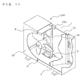
- Fig. 11 is a perspective view of an outdoor unit 100 of an air-conditioning apparatus according to Embodiment 5 of the present invention.
- the heat exchanger 1 is provided in the outdoor unit 100 in a state where Embodiments 1 to 4 are combined.
- the heat exchanger 1 keeps a self-standing state on the base plate 3, and hence assembling of the outdoor unit 100 is facilitated.
- the heat exchanger 1 is firmly fixed over the upper portion and the lower portion thereof without being in contact directly with members such as the partition plate 5 and the front portion 27 which are made of a metal that is electrically nobler than aluminum.
- the heat exchanger 1 is able to keep a stable assemble state without being tilted relative to the base plate 3, and the heat exchanger 1 is restrained from being oscillated even in response to an excessive impact or vibration during transportation or operation of the air-conditioning apparatus. Therefore, it is possible to provide the outdoor unit 100 of the air-conditioning apparatus which has high reliability for a long period of time.
- the present invention is applicable to an outdoor unit of an air-conditioning apparatus such as a room air-conditioner or a package air-conditioner which includes an aluminum heat exchanger in which fins and pipes are made of aluminum or an aluminum alloy.
Landscapes
- Engineering & Computer Science (AREA)
- Chemical & Material Sciences (AREA)
- Combustion & Propulsion (AREA)
- Mechanical Engineering (AREA)
- General Engineering & Computer Science (AREA)
- Other Air-Conditioning Systems (AREA)
- Heat-Exchange Devices With Radiators And Conduit Assemblies (AREA)
Applications Claiming Priority (1)
| Application Number | Priority Date | Filing Date | Title |
|---|---|---|---|
| JP2013004690A JP6066736B2 (ja) | 2013-01-15 | 2013-01-15 | 空気調和機の室外機 |
Publications (3)
| Publication Number | Publication Date |
|---|---|
| EP2754974A2 true EP2754974A2 (fr) | 2014-07-16 |
| EP2754974A3 EP2754974A3 (fr) | 2018-03-28 |
| EP2754974B1 EP2754974B1 (fr) | 2022-07-20 |
Family
ID=49683453
Family Applications (1)
| Application Number | Title | Priority Date | Filing Date |
|---|---|---|---|
| EP13193973.8A Active EP2754974B1 (fr) | 2013-01-15 | 2013-11-22 | Unité extérieure de climatiseur |
Country Status (3)
| Country | Link |
|---|---|
| EP (1) | EP2754974B1 (fr) |
| JP (1) | JP6066736B2 (fr) |
| CN (2) | CN103925654B (fr) |
Cited By (3)
| Publication number | Priority date | Publication date | Assignee | Title |
|---|---|---|---|---|
| US20170370597A1 (en) * | 2014-10-27 | 2017-12-28 | Daikin Industries, Ltd. | Heat exchanger assembly and outdoor unit of refrigerating apparatus |
| EP3527898A4 (fr) * | 2016-10-17 | 2019-10-09 | Mitsubishi Electric Corporation | Unité extérieure pour un dispositif de climatisation |
| US10816227B2 (en) | 2016-07-25 | 2020-10-27 | Mitsubishi Electric Corporation | Outdoor unit for an air-conditioning apparatus having L-shaped heat exchanger and placement plate for same |
Families Citing this family (9)
| Publication number | Priority date | Publication date | Assignee | Title |
|---|---|---|---|---|
| JP6066736B2 (ja) * | 2013-01-15 | 2017-01-25 | 三菱電機株式会社 | 空気調和機の室外機 |
| CN107208907B (zh) * | 2015-02-17 | 2019-10-29 | 三菱电机株式会社 | 室外机 |
| JP6640500B2 (ja) * | 2015-09-08 | 2020-02-05 | 日立ジョンソンコントロールズ空調株式会社 | 空気調和装置の室外機 |
| JP6545277B2 (ja) * | 2015-10-28 | 2019-07-17 | 三菱電機株式会社 | 空気調和機の室外機 |
| CN105972716B (zh) * | 2016-06-23 | 2020-09-04 | 珠海格力电器股份有限公司 | 钣金件连接结构及空调室外机 |
| JP6820750B2 (ja) * | 2017-01-04 | 2021-01-27 | 日立ジョンソンコントロールズ空調株式会社 | 室外機、および冷凍サイクル装置 |
| CN106705236B (zh) * | 2017-01-18 | 2022-06-14 | 美的集团武汉制冷设备有限公司 | 空调室内机和空调器 |
| CN209013353U (zh) * | 2017-02-02 | 2019-06-21 | 三菱电机株式会社 | 空调机的室外机 |
| WO2018163727A1 (fr) * | 2017-03-10 | 2018-09-13 | ダイキン工業株式会社 | Dispositif frigorifique |
Citations (2)
| Publication number | Priority date | Publication date | Assignee | Title |
|---|---|---|---|---|
| JP4479207B2 (ja) | 2003-10-09 | 2010-06-09 | パナソニック株式会社 | 空気調和機の室外ユニット |
| JP2011145029A (ja) | 2010-01-18 | 2011-07-28 | Sharp Corp | 空気調和機 |
Family Cites Families (10)
| Publication number | Priority date | Publication date | Assignee | Title |
|---|---|---|---|---|
| JPS5699371U (fr) * | 1979-12-27 | 1981-08-05 | ||
| JPS6136270U (ja) * | 1984-08-03 | 1986-03-06 | 三洋電機株式会社 | 熱交換ユニツト |
| JPH0612381Y2 (ja) * | 1987-02-27 | 1994-03-30 | 昭和アルミニウム株式会社 | 熱交換器 |
| JPH0399607U (fr) * | 1990-01-31 | 1991-10-18 | ||
| JP2555867Y2 (ja) * | 1990-10-31 | 1997-11-26 | 昭和アルミニウム 株式会社 | 熱交換器 |
| JP5028201B2 (ja) * | 2007-09-25 | 2012-09-19 | 三洋電機株式会社 | 空気調和装置の室外ユニット |
| JP4388994B1 (ja) * | 2008-12-25 | 2009-12-24 | シャープ株式会社 | 熱交換器 |
| CN202002540U (zh) * | 2011-03-30 | 2011-10-05 | Tcl空调器(中山)有限公司 | 一种微通道换热器的固定装置 |
| CN202057118U (zh) * | 2011-05-04 | 2011-11-30 | 海信(山东)空调有限公司 | 空调器室外机冷凝器及室外机 |
| JP6066736B2 (ja) * | 2013-01-15 | 2017-01-25 | 三菱電機株式会社 | 空気調和機の室外機 |
-
2013
- 2013-01-15 JP JP2013004690A patent/JP6066736B2/ja active Active
- 2013-11-22 EP EP13193973.8A patent/EP2754974B1/fr active Active
- 2013-11-29 CN CN201310629152.3A patent/CN103925654B/zh active Active
- 2013-11-29 CN CN201320775681.XU patent/CN203797820U/zh not_active Withdrawn - After Issue
Patent Citations (2)
| Publication number | Priority date | Publication date | Assignee | Title |
|---|---|---|---|---|
| JP4479207B2 (ja) | 2003-10-09 | 2010-06-09 | パナソニック株式会社 | 空気調和機の室外ユニット |
| JP2011145029A (ja) | 2010-01-18 | 2011-07-28 | Sharp Corp | 空気調和機 |
Cited By (4)
| Publication number | Priority date | Publication date | Assignee | Title |
|---|---|---|---|---|
| US20170370597A1 (en) * | 2014-10-27 | 2017-12-28 | Daikin Industries, Ltd. | Heat exchanger assembly and outdoor unit of refrigerating apparatus |
| US10782035B2 (en) | 2014-10-27 | 2020-09-22 | Daikin Industries, Ltd. | Heat exchanger assembly and outdoor unit of refrigerating apparatus |
| US10816227B2 (en) | 2016-07-25 | 2020-10-27 | Mitsubishi Electric Corporation | Outdoor unit for an air-conditioning apparatus having L-shaped heat exchanger and placement plate for same |
| EP3527898A4 (fr) * | 2016-10-17 | 2019-10-09 | Mitsubishi Electric Corporation | Unité extérieure pour un dispositif de climatisation |
Also Published As
| Publication number | Publication date |
|---|---|
| CN103925654B (zh) | 2016-09-14 |
| EP2754974B1 (fr) | 2022-07-20 |
| EP2754974A3 (fr) | 2018-03-28 |
| JP2014137157A (ja) | 2014-07-28 |
| CN103925654A (zh) | 2014-07-16 |
| JP6066736B2 (ja) | 2017-01-25 |
| CN203797820U (zh) | 2014-08-27 |
Similar Documents
| Publication | Publication Date | Title |
|---|---|---|
| EP2754974B1 (fr) | Unité extérieure de climatiseur | |
| US20050205552A1 (en) | Electric heater | |
| CN107110521B (zh) | 热交换器装配体和冷冻装置的室外单元 | |
| KR100313634B1 (ko) | 열교환기 | |
| EP2921808B1 (fr) | Tube de transmission de chaleur plat, procédé de fabrication d'échangeur de chaleur de type tube à ailettes transversales équipé de celui-ci, échangeur de chaleur de type tube à ailettes transversales fabriqué utilisant ledit procédé | |
| JP4389793B2 (ja) | 冷媒放熱器の取付構造 | |
| CN109804216B (zh) | 热交换器和冷冻装置的室外单元 | |
| JP5516387B2 (ja) | 冷凍装置の室外ユニット | |
| JP5931043B2 (ja) | 空気調和機の室外機 | |
| EP3726174B1 (fr) | Échangeur de chaleur sans ailettes et dispositif à cycle frigorifique | |
| JP6136124B2 (ja) | 熱交換器の製造方法および熱交換器 | |
| JP6218684B2 (ja) | 空気調和機の室外機 | |
| KR20140094126A (ko) | 열교환기 및 그 제조방법 | |
| JP2009144982A (ja) | 空気調和機 | |
| JP5963958B2 (ja) | 空気調和機の室外機、及び空気調和機の室外機の製造方法 | |
| US20160296993A1 (en) | Method for forming end plate for heat exchanger and heat exchanger equipped with end plate formed with this method | |
| KR101884443B1 (ko) | 열교환기 | |
| WO2016185917A1 (fr) | Échangeur de chaleur équipé d'un réceptacle de liquide | |
| JP6399008B2 (ja) | 熱交換器、及びそれを備えた冷凍装置の室外ユニット | |
| JP6723385B2 (ja) | 熱交換器、熱交換器を備えた空気調和機、及び熱交換器の製造方法 | |
| JP2021131203A (ja) | 熱交換器 | |
| JP2018071931A (ja) | 凝縮器 | |
| JP2009115342A (ja) | 熱交換器 | |
| JP2015031435A (ja) | 空気調和装置の室外ユニット | |
| JP5609624B2 (ja) | 冷凍装置の室外ユニット |
Legal Events
| Date | Code | Title | Description |
|---|---|---|---|
| PUAI | Public reference made under article 153(3) epc to a published international application that has entered the european phase |
Free format text: ORIGINAL CODE: 0009012 |
|
| 17P | Request for examination filed |
Effective date: 20131122 |
|
| AK | Designated contracting states |
Kind code of ref document: A2 Designated state(s): AL AT BE BG CH CY CZ DE DK EE ES FI FR GB GR HR HU IE IS IT LI LT LU LV MC MK MT NL NO PL PT RO RS SE SI SK SM TR |
|
| AX | Request for extension of the european patent |
Extension state: BA ME |
|
| PUAL | Search report despatched |
Free format text: ORIGINAL CODE: 0009013 |
|
| AK | Designated contracting states |
Kind code of ref document: A3 Designated state(s): AL AT BE BG CH CY CZ DE DK EE ES FI FR GB GR HR HU IE IS IT LI LT LU LV MC MK MT NL NO PL PT RO RS SE SI SK SM TR |
|
| AX | Request for extension of the european patent |
Extension state: BA ME |
|
| RIC1 | Information provided on ipc code assigned before grant |
Ipc: F24F 13/30 20060101ALI20180220BHEP Ipc: F24F 1/16 20110101ALI20180220BHEP Ipc: F24F 1/14 20110101ALI20180220BHEP Ipc: F24F 13/20 20060101AFI20180220BHEP |
|
| STAA | Information on the status of an ep patent application or granted ep patent |
Free format text: STATUS: REQUEST FOR EXAMINATION WAS MADE |
|
| R17P | Request for examination filed (corrected) |
Effective date: 20180608 |
|
| RBV | Designated contracting states (corrected) |
Designated state(s): AL AT BE BG CH CY CZ DE DK EE ES FI FR GB GR HR HU IE IS IT LI LT LU LV MC MK MT NL NO PL PT RO RS SE SI SK SM TR |
|
| STAA | Information on the status of an ep patent application or granted ep patent |
Free format text: STATUS: EXAMINATION IS IN PROGRESS |
|
| 17Q | First examination report despatched |
Effective date: 20200313 |
|
| STAA | Information on the status of an ep patent application or granted ep patent |
Free format text: STATUS: EXAMINATION IS IN PROGRESS |
|
| GRAP | Despatch of communication of intention to grant a patent |
Free format text: ORIGINAL CODE: EPIDOSNIGR1 |
|
| STAA | Information on the status of an ep patent application or granted ep patent |
Free format text: STATUS: GRANT OF PATENT IS INTENDED |
|
| INTG | Intention to grant announced |
Effective date: 20220207 |
|
| GRAS | Grant fee paid |
Free format text: ORIGINAL CODE: EPIDOSNIGR3 |
|
| GRAA | (expected) grant |
Free format text: ORIGINAL CODE: 0009210 |
|
| STAA | Information on the status of an ep patent application or granted ep patent |
Free format text: STATUS: THE PATENT HAS BEEN GRANTED |
|
| AK | Designated contracting states |
Kind code of ref document: B1 Designated state(s): AL AT BE BG CH CY CZ DE DK EE ES FI FR GB GR HR HU IE IS IT LI LT LU LV MC MK MT NL NO PL PT RO RS SE SI SK SM TR |
|
| REG | Reference to a national code |
Ref country code: GB Ref legal event code: FG4D |
|
| REG | Reference to a national code |
Ref country code: CH Ref legal event code: EP |
|
| REG | Reference to a national code |
Ref country code: DE Ref legal event code: R096 Ref document number: 602013082096 Country of ref document: DE |
|
| REG | Reference to a national code |
Ref country code: AT Ref legal event code: REF Ref document number: 1505750 Country of ref document: AT Kind code of ref document: T Effective date: 20220815 |
|
| REG | Reference to a national code |
Ref country code: IE Ref legal event code: FG4D |
|
| REG | Reference to a national code |
Ref country code: LT Ref legal event code: MG9D |
|
| REG | Reference to a national code |
Ref country code: NL Ref legal event code: MP Effective date: 20220720 |
|
| PG25 | Lapsed in a contracting state [announced via postgrant information from national office to epo] |
Ref country code: SE Free format text: LAPSE BECAUSE OF FAILURE TO SUBMIT A TRANSLATION OF THE DESCRIPTION OR TO PAY THE FEE WITHIN THE PRESCRIBED TIME-LIMIT Effective date: 20220720 Ref country code: RS Free format text: LAPSE BECAUSE OF FAILURE TO SUBMIT A TRANSLATION OF THE DESCRIPTION OR TO PAY THE FEE WITHIN THE PRESCRIBED TIME-LIMIT Effective date: 20220720 Ref country code: PT Free format text: LAPSE BECAUSE OF FAILURE TO SUBMIT A TRANSLATION OF THE DESCRIPTION OR TO PAY THE FEE WITHIN THE PRESCRIBED TIME-LIMIT Effective date: 20221121 Ref country code: NO Free format text: LAPSE BECAUSE OF FAILURE TO SUBMIT A TRANSLATION OF THE DESCRIPTION OR TO PAY THE FEE WITHIN THE PRESCRIBED TIME-LIMIT Effective date: 20221020 Ref country code: NL Free format text: LAPSE BECAUSE OF FAILURE TO SUBMIT A TRANSLATION OF THE DESCRIPTION OR TO PAY THE FEE WITHIN THE PRESCRIBED TIME-LIMIT Effective date: 20220720 Ref country code: LV Free format text: LAPSE BECAUSE OF FAILURE TO SUBMIT A TRANSLATION OF THE DESCRIPTION OR TO PAY THE FEE WITHIN THE PRESCRIBED TIME-LIMIT Effective date: 20220720 Ref country code: LT Free format text: LAPSE BECAUSE OF FAILURE TO SUBMIT A TRANSLATION OF THE DESCRIPTION OR TO PAY THE FEE WITHIN THE PRESCRIBED TIME-LIMIT Effective date: 20220720 Ref country code: FI Free format text: LAPSE BECAUSE OF FAILURE TO SUBMIT A TRANSLATION OF THE DESCRIPTION OR TO PAY THE FEE WITHIN THE PRESCRIBED TIME-LIMIT Effective date: 20220720 Ref country code: ES Free format text: LAPSE BECAUSE OF FAILURE TO SUBMIT A TRANSLATION OF THE DESCRIPTION OR TO PAY THE FEE WITHIN THE PRESCRIBED TIME-LIMIT Effective date: 20220720 |
|
| REG | Reference to a national code |
Ref country code: AT Ref legal event code: MK05 Ref document number: 1505750 Country of ref document: AT Kind code of ref document: T Effective date: 20220720 |
|
| PG25 | Lapsed in a contracting state [announced via postgrant information from national office to epo] |
Ref country code: PL Free format text: LAPSE BECAUSE OF FAILURE TO SUBMIT A TRANSLATION OF THE DESCRIPTION OR TO PAY THE FEE WITHIN THE PRESCRIBED TIME-LIMIT Effective date: 20220720 Ref country code: IS Free format text: LAPSE BECAUSE OF FAILURE TO SUBMIT A TRANSLATION OF THE DESCRIPTION OR TO PAY THE FEE WITHIN THE PRESCRIBED TIME-LIMIT Effective date: 20221120 Ref country code: HR Free format text: LAPSE BECAUSE OF FAILURE TO SUBMIT A TRANSLATION OF THE DESCRIPTION OR TO PAY THE FEE WITHIN THE PRESCRIBED TIME-LIMIT Effective date: 20220720 Ref country code: GR Free format text: LAPSE BECAUSE OF FAILURE TO SUBMIT A TRANSLATION OF THE DESCRIPTION OR TO PAY THE FEE WITHIN THE PRESCRIBED TIME-LIMIT Effective date: 20221021 |
|
| REG | Reference to a national code |
Ref country code: DE Ref legal event code: R097 Ref document number: 602013082096 Country of ref document: DE |
|
| PG25 | Lapsed in a contracting state [announced via postgrant information from national office to epo] |
Ref country code: SM Free format text: LAPSE BECAUSE OF FAILURE TO SUBMIT A TRANSLATION OF THE DESCRIPTION OR TO PAY THE FEE WITHIN THE PRESCRIBED TIME-LIMIT Effective date: 20220720 Ref country code: RO Free format text: LAPSE BECAUSE OF FAILURE TO SUBMIT A TRANSLATION OF THE DESCRIPTION OR TO PAY THE FEE WITHIN THE PRESCRIBED TIME-LIMIT Effective date: 20220720 Ref country code: DK Free format text: LAPSE BECAUSE OF FAILURE TO SUBMIT A TRANSLATION OF THE DESCRIPTION OR TO PAY THE FEE WITHIN THE PRESCRIBED TIME-LIMIT Effective date: 20220720 Ref country code: CZ Free format text: LAPSE BECAUSE OF FAILURE TO SUBMIT A TRANSLATION OF THE DESCRIPTION OR TO PAY THE FEE WITHIN THE PRESCRIBED TIME-LIMIT Effective date: 20220720 Ref country code: AT Free format text: LAPSE BECAUSE OF FAILURE TO SUBMIT A TRANSLATION OF THE DESCRIPTION OR TO PAY THE FEE WITHIN THE PRESCRIBED TIME-LIMIT Effective date: 20220720 |
|
| PLBE | No opposition filed within time limit |
Free format text: ORIGINAL CODE: 0009261 |
|
| STAA | Information on the status of an ep patent application or granted ep patent |
Free format text: STATUS: NO OPPOSITION FILED WITHIN TIME LIMIT |
|
| PG25 | Lapsed in a contracting state [announced via postgrant information from national office to epo] |
Ref country code: SK Free format text: LAPSE BECAUSE OF FAILURE TO SUBMIT A TRANSLATION OF THE DESCRIPTION OR TO PAY THE FEE WITHIN THE PRESCRIBED TIME-LIMIT Effective date: 20220720 Ref country code: EE Free format text: LAPSE BECAUSE OF FAILURE TO SUBMIT A TRANSLATION OF THE DESCRIPTION OR TO PAY THE FEE WITHIN THE PRESCRIBED TIME-LIMIT Effective date: 20220720 |
|
| REG | Reference to a national code |
Ref country code: DE Ref legal event code: R119 Ref document number: 602013082096 Country of ref document: DE |
|
| P01 | Opt-out of the competence of the unified patent court (upc) registered |
Effective date: 20230512 |
|
| 26N | No opposition filed |
Effective date: 20230421 |
|
| PG25 | Lapsed in a contracting state [announced via postgrant information from national office to epo] |
Ref country code: MC Free format text: LAPSE BECAUSE OF FAILURE TO SUBMIT A TRANSLATION OF THE DESCRIPTION OR TO PAY THE FEE WITHIN THE PRESCRIBED TIME-LIMIT Effective date: 20220720 Ref country code: AL Free format text: LAPSE BECAUSE OF FAILURE TO SUBMIT A TRANSLATION OF THE DESCRIPTION OR TO PAY THE FEE WITHIN THE PRESCRIBED TIME-LIMIT Effective date: 20220720 |
|
| REG | Reference to a national code |
Ref country code: CH Ref legal event code: PL |
|
| GBPC | Gb: european patent ceased through non-payment of renewal fee |
Effective date: 20221122 |
|
| REG | Reference to a national code |
Ref country code: BE Ref legal event code: MM Effective date: 20221130 |
|
| PG25 | Lapsed in a contracting state [announced via postgrant information from national office to epo] |
Ref country code: LI Free format text: LAPSE BECAUSE OF NON-PAYMENT OF DUE FEES Effective date: 20221130 Ref country code: CH Free format text: LAPSE BECAUSE OF NON-PAYMENT OF DUE FEES Effective date: 20221130 |
|
| PG25 | Lapsed in a contracting state [announced via postgrant information from national office to epo] |
Ref country code: SI Free format text: LAPSE BECAUSE OF FAILURE TO SUBMIT A TRANSLATION OF THE DESCRIPTION OR TO PAY THE FEE WITHIN THE PRESCRIBED TIME-LIMIT Effective date: 20220720 Ref country code: LU Free format text: LAPSE BECAUSE OF NON-PAYMENT OF DUE FEES Effective date: 20221122 |
|
| PG25 | Lapsed in a contracting state [announced via postgrant information from national office to epo] |
Ref country code: IE Free format text: LAPSE BECAUSE OF NON-PAYMENT OF DUE FEES Effective date: 20221122 Ref country code: GB Free format text: LAPSE BECAUSE OF NON-PAYMENT OF DUE FEES Effective date: 20221122 Ref country code: DE Free format text: LAPSE BECAUSE OF NON-PAYMENT OF DUE FEES Effective date: 20230601 |
|
| PG25 | Lapsed in a contracting state [announced via postgrant information from national office to epo] |
Ref country code: FR Free format text: LAPSE BECAUSE OF NON-PAYMENT OF DUE FEES Effective date: 20221130 Ref country code: BE Free format text: LAPSE BECAUSE OF NON-PAYMENT OF DUE FEES Effective date: 20221130 |
|
| PGFP | Annual fee paid to national office [announced via postgrant information from national office to epo] |
Ref country code: IT Payment date: 20231010 Year of fee payment: 11 |
|
| PG25 | Lapsed in a contracting state [announced via postgrant information from national office to epo] |
Ref country code: HU Free format text: LAPSE BECAUSE OF FAILURE TO SUBMIT A TRANSLATION OF THE DESCRIPTION OR TO PAY THE FEE WITHIN THE PRESCRIBED TIME-LIMIT; INVALID AB INITIO Effective date: 20131122 |
|
| PG25 | Lapsed in a contracting state [announced via postgrant information from national office to epo] |
Ref country code: CY Free format text: LAPSE BECAUSE OF FAILURE TO SUBMIT A TRANSLATION OF THE DESCRIPTION OR TO PAY THE FEE WITHIN THE PRESCRIBED TIME-LIMIT Effective date: 20220720 |