EP2754584A2 - Flurförderzeug mit Warnvorrichtung - Google Patents
Flurförderzeug mit Warnvorrichtung Download PDFInfo
- Publication number
- EP2754584A2 EP2754584A2 EP13199435.2A EP13199435A EP2754584A2 EP 2754584 A2 EP2754584 A2 EP 2754584A2 EP 13199435 A EP13199435 A EP 13199435A EP 2754584 A2 EP2754584 A2 EP 2754584A2
- Authority
- EP
- European Patent Office
- Prior art keywords
- truck
- area
- warning area
- travel
- truck according
- Prior art date
- Legal status (The legal status is an assumption and is not a legal conclusion. Google has not performed a legal analysis and makes no representation as to the accuracy of the status listed.)
- Granted
Links
Images

Classifications
-
- B—PERFORMING OPERATIONS; TRANSPORTING
- B60—VEHICLES IN GENERAL
- B60Q—ARRANGEMENT OF SIGNALLING OR LIGHTING DEVICES, THE MOUNTING OR SUPPORTING THEREOF OR CIRCUITS THEREFOR, FOR VEHICLES IN GENERAL
- B60Q1/00—Arrangement of optical signalling or lighting devices, the mounting or supporting thereof or circuits therefor
- B60Q1/26—Arrangement of optical signalling or lighting devices, the mounting or supporting thereof or circuits therefor the devices being primarily intended to indicate the vehicle, or parts thereof, or to give signals, to other traffic
- B60Q1/50—Arrangement of optical signalling or lighting devices, the mounting or supporting thereof or circuits therefor the devices being primarily intended to indicate the vehicle, or parts thereof, or to give signals, to other traffic for indicating other intentions or conditions, e.g. request for waiting or overtaking
-
- B—PERFORMING OPERATIONS; TRANSPORTING
- B66—HOISTING; LIFTING; HAULING
- B66F—HOISTING, LIFTING, HAULING OR PUSHING, NOT OTHERWISE PROVIDED FOR, e.g. DEVICES WHICH APPLY A LIFTING OR PUSHING FORCE DIRECTLY TO THE SURFACE OF A LOAD
- B66F17/00—Safety devices, e.g. for limiting or indicating lifting force
- B66F17/003—Safety devices, e.g. for limiting or indicating lifting force for fork-lift trucks
-
- B—PERFORMING OPERATIONS; TRANSPORTING
- B66—HOISTING; LIFTING; HAULING
- B66F—HOISTING, LIFTING, HAULING OR PUSHING, NOT OTHERWISE PROVIDED FOR, e.g. DEVICES WHICH APPLY A LIFTING OR PUSHING FORCE DIRECTLY TO THE SURFACE OF A LOAD
- B66F9/00—Devices for lifting or lowering bulky or heavy goods for loading or unloading purposes
- B66F9/06—Devices for lifting or lowering bulky or heavy goods for loading or unloading purposes movable, with their loads, on wheels or the like, e.g. fork-lift trucks
- B66F9/075—Constructional features or details
- B66F9/07504—Accessories, e.g. for towing, charging, locking
-
- B—PERFORMING OPERATIONS; TRANSPORTING
- B60—VEHICLES IN GENERAL
- B60Q—ARRANGEMENT OF SIGNALLING OR LIGHTING DEVICES, THE MOUNTING OR SUPPORTING THEREOF OR CIRCUITS THEREFOR, FOR VEHICLES IN GENERAL
- B60Q2400/00—Special features or arrangements of exterior signal lamps for vehicles
- B60Q2400/50—Projected symbol or information, e.g. onto the road or car body
-
- B—PERFORMING OPERATIONS; TRANSPORTING
- B60—VEHICLES IN GENERAL
- B60Q—ARRANGEMENT OF SIGNALLING OR LIGHTING DEVICES, THE MOUNTING OR SUPPORTING THEREOF OR CIRCUITS THEREFOR, FOR VEHICLES IN GENERAL
- B60Q2800/00—Features related to particular types of vehicles not otherwise provided for
- B60Q2800/20—Utility vehicles, e.g. for agriculture, construction work
Definitions
- the invention relates to a truck with a warning device that can project a light effect on the road.
- Industrial trucks are known, for example in embodiments as counterbalance forklifts, reach trucks and warehouse equipment.
- these three types of industrial trucks are widely used on factory premises and in storage areas in which persons are also present, while at the same time the visibility is limited by storage racks and stored loads and the spatial conditions.
- a long-known and widespread solution to this problem is rotating flashing lights or flashing lights, which are located in the upper area or on a driver's roof of the trucks, often as yellow warning lights.
- a disadvantage of the flashing warning lights is that due to the often large number of simultaneously moving trucks and the constantly flashing light, which is still perceptible about reflections constantly in all areas of a camp, they are often not specifically observed, or is not perceived that a concrete danger approached by a vehicle. Also, the constant visibility of the warning lights can be perceived as unpleasant and lead to acceptance problems.
- the safety light is usually projected at a fixed distance in front of the truck and / or, in the case of the reverse, behind the truck on the road.
- the lighting effect is switched on in each case in the direction of travel and, in an alternative embodiment, can change its distance from the truck and / or its size depending on the driving speed.
- a disadvantage of this prior art is that a light spot alone is not always optimally perceptible. Furthermore, it is disadvantageous in the embodiments that vary depending on the driving speed, thereby creating effort in the implementation.
- the invention is therefore based on the object to provide an industrial truck of the type mentioned, with which the warning function for people in the vicinity of the truck is improved.
- the object is achieved in that in a truck with a warning device that can project a light effect on the road, the light effect has a projection with at least one front in the direction of travel of the truck front warning area and a rear in the direction of travel of the truck rear warning range , wherein the projection surface is represented by a boundary line and / or an illuminated surface.
- the respective warning area can be marked as part of the projection area solely by an illuminated boundary line.
- the entire surface may be illuminated.
- the entire surface of the warning areas or the projection surface is illuminated and the boundary line is particularly highlighted, for example, by a higher intensity.
- a simple geometric shape can be taken without major calculations being required.
- a flare or spot as Warning device is used, but a flat warning area is marked, which extends to the truck zoom in, more attention is attracted to people who are entering or approaching this area. This is especially true when the projection surface is illuminated areally.
- an illuminated area for the warning areas or the projection area may extend as far as the industrial truck.
- a warning surface or projection surface formed solely by a boundary line can be distinguished by the fact that the boundary line is always formed as far as the vehicle rim of the industrial truck.
- the front warning area and / or the rear warning area may consist of a rectangle extending across the width of the truck.
- the front warning area and / or the rear warning area consist of a trapezoid whose base corresponds to the width of the truck.
- the projection surface is a total area surrounding the truck, which extends in front of and behind the truck at a greater distance from the truck.
- the projection surface can be an ellipse enclosing the industrial truck.
- trucks that are operated by a rider driving have one or more steered wheels with a very large steering angle and very small turning circles.
- Examples of this are reach trucks and storage and retrieval systems, which have a rear wheel consisting of a single or multiple wheels whose wheels can be taken, with partly turning angle are achieved practically to transverse to the vehicle longitudinal axis.
- this also applies to counterbalanced forklifts with steered rear axle.
- the rear of the vehicle pivots very much laterally at full steering angle.
- a load-bearing device, in particular a load fork mounted in front of the vehicle sweeps the space laterally when cornering.
- the respective warning area lying forward in the direction of travel is arranged in front of a load handling device such as a load fork in the direction in which the load fork swings. For example, in a forward-driven left turn, this is left in the longitudinal direction next to or in front of the fork.
- the warning area located at the rear in relation to the direction of travel is oriented towards the outside.
- the warning area located at the front in the direction of travel can consist of a rectangle extending over the width of the truck with a semicircle which adjoins the inside of the curved path.
- the complete warning area can be displayed in the direction of travel and be warned during cornering in addition to the lateral movement.
- the described shape is geometrically simple and easy to implement.
- the warning area located at the rear in the direction of travel may essentially consist of a three-quarter circle whose center approximately corresponds to the outer corner of the vehicle on the curved path.
- the truck may be a counterbalanced forklift with steered rear wheels.
- the illuminated area can increase as a projection surface in the intensity in the direction of the truck.
- the view is automatically directed towards the truck with the increasing brightness.
- the size of the projection surface and / or the intensity increases with the driving speed.
- the light effect can be generated by at least one lighting device mounted on a driver's roof.
- the relatively high position allows precise illumination of the boundary line or up to the boundary line.
- the light effect can be generated by at least one lighting device mounted in the region of a vehicle floor.
- Low-mounted lighting devices for example, at the edge of the truck in the area of the underbody or for example at the bottom of the rear weight allow lighting without it comes to shading about by the load receiving device when the lighting device is mounted on a driving roof.
- the lighting device may be a laser.
- the lighting device is formed from light-emitting diodes.
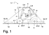
- the Fig. 1 shows a side view of a schematic illustration of an industrial truck 1 according to the invention, here for example a counterbalance forklift 2, with a first, front mounted lighting device 3 and a rear mounted second lighting device 3, each in the form of a laser. 4
- the counterbalance forklift 2 has a guided on a mast 5 load handling device 6 in the form of a fork formed by two forks 7.
- the mast 5 is above a front axle with front wheels. 8 arranged over which the counterbalance forklift 2 is driven.
- Behind the mast 5 is a driver's roof 9 and a counterweight 10.
- Below the counterweight 10 are steered rear wheels 11, with which the counterbalance forklift 2 is directed.
- a driver's seat 12 is arranged with a steering wheel 13.
- the first, front lighting device 3, as well as the second, rear lighting device 3 are preferably arranged on the driver's roof 9 in the upper area and send laser light 14 of the respective laser 4 or bundled light of a light source, such as light emitting diodes, as a light effect, through the one Projection surface 16 is projected onto the roadway 18, wherein the projection surface 16 has a front warning area 15 and a rear warning area 17.
- the projection surface 16 or the front warning area 15 as well as the rear warning area 17 can be marked by a boundary line 19 being marked by light.
- the entire area of the projection surface 16 can also be illuminated, wherein it is also possible to increase the intensity of the light with increasing proximity to the industrial truck 1.
- Another lighting device 20 is mounted in the area of the front vehicle floor and illuminates in the front warning areas 15. Likewise, in the rear lower area of the counterweight 10, a further lighting device 21 is arranged, which lights up in the rear warning areas 17. These further lighting devices 20, 21 may be provided on the driver's safety roof 9 in addition to or as an alternative to the lighting devices 3. It is also possible to illuminate areas in the front warning area 15 or rear warning area 17 of the projection area 16, which are otherwise shaded by parts of the lifting mast 5 or of the counterweight 10th
- the invention is not limited to the example described here of a counterbalance forklift truck 2 as an industrial truck 1 and can be applied to all types of industrial trucks
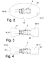
- the Fig. 2 schematically shows the truck of Fig. 1 with a first embodiment of the projection surface 16 in the form of an ellipse 22, which completely surrounds the forklift 2.
- the ellipse 22 is shaped so long stretched, that results in front of the forklift 2, the front warning area 15 and behind the forklift 2, the rear warning area 17.
- the projection surface is also located laterally of the forklift 2.
- the Fig. 3 schematically shows the truck of Fig. 1 with a second embodiment of the projection surface 16, in which the front warning area 15 consists of a trapezoid 23 whose base line corresponds to the width of the forklift 2 and which widened further in front of the forklift 2.
- the rear warning surface 17 consists of another trapezoid 23 whose base line also corresponds to the width of the forklift 2 and widened further behind the forklift 2.
- Fig. 4 schematically shows the truck of Fig. 1 with a third embodiment of a projection surface 16, in which the front warning area 15 consists of a rectangle 24 that extends across the width of the forklift 2. Likewise, the rear warning surface 17 consists of a further rectangle 24 which extends across the width of the forklift 2.
- the Fig. 5a shows the embodiment of the Fig. 4 with the projection surface 16 when cornering forward right, as indicated by the arrow.
- the directions "right” and “left” are defined with respect to a vehicle longitudinal axis with a view to the front of the vehicle regardless of a direction of travel.
- the front in the direction of travel of the forklift 2 warning area 15 of the projection surface 16 is to the inside of the curved path, right here, oriented, and consists of an across the width of the truck extending rectangle, the curve inner side line is replaced by a semicircle 25.
- the rear with respect to the direction of travel of the forklift 2 warning area 17 of the projection 16 is oriented to the outside of the curved path, here on the left, and consists of a three-quarter circle 26, wherein the center 27 approximately at the position of the left and thus curve outside, rear corner of the Forklift 2 is located. It can, as soon as the steering angle of the steering wheel 13 in the direction of travel forward exceeds a certain value, the projection surface 16 from the representation in the Fig. 4 in the form of the Fig. 5a being transformed.
- the Fig. 5b shows the embodiment of the Fig. 4 with the projection surface 16 when cornering forward left, as indicated by the arrow.
- the in the direction of travel of the Forklift 2 front warning area 15 of the projection surface 16 is oriented to the inside of the curved path, here on the left, and consists of a rectangle extending over the width of the truck, the curve-inner side line is replaced by a semicircle 25.
- the rear with respect to the direction of travel of the forklift 2 warning area 17 of the projection 16 is oriented to the outside of the curved path, here right, and in turn consists of a three-quarter circle 26, wherein its center 27 is approximately at the position of the right and thus curve outside, rear corner of the forklift 2 is located.
- the Fig. 5c shows the embodiment of the Fig. 4 with the projection surface 16 when cornering backward right, as indicated by the arrow.
- the front in the direction of travel of the forklift 2 and formed of rectangle and semicircle 25 warning area 15 of the screen 16 is to the inside of the curved path, right here, oriented.
- the rear in relation to the direction of travel of the forklift 2 warning area 17 of the projection surface 16 in turn consists of a three-quarter circle 26 with the approximate center 27, a front corner of the vehicle in this case foundatorial.
- the Fig. 5d shows the embodiment of the Fig. 4 with the projection surface 16 when cornering backward left, as indicated by the arrow.
- the front in the direction of travel of the forklift 2 and formed of rectangle and semicircle 25 warning area 15 of the projection 16 is to the inside of the curved path, left, oriented.
- the rear in relation to the direction of travel of the forklift 2 warning area 17 of the projection surface 16 in turn consists of a three-quarter circle 26, the center 27 is located approximately at the position of the right and thus curve outside, front corner of the forklift 2.
Landscapes
- Engineering & Computer Science (AREA)
- Mechanical Engineering (AREA)
- Structural Engineering (AREA)
- Life Sciences & Earth Sciences (AREA)
- Geology (AREA)
- Transportation (AREA)
- Civil Engineering (AREA)
- Lighting Device Outwards From Vehicle And Optical Signal (AREA)
- Forklifts And Lifting Vehicles (AREA)
Abstract
Description
- Die Erfindung betrifft ein Flurförderzeug mit einer Warnvorrichtung, die einen Lichteffekt auf die Fahrbahn projizieren kann.
- Flurförderzeuge sind beispielsweise in Ausführungsformen als Gegengewichtsgabelstapler, Schubmaststapler sowie Lagertechnikgeräte bekannt. Insbesondere diese drei Arten von Flurförderzeugen werden in großem Umfang auf Betriebsgeländen und in Lagerbereichen eingesetzt, in denen sich auch Personen aufhalten, während gleichzeitig die Sichtverhältnisse durch Lagerregale und eingelagerte Lasten sowie die räumlichen Umstände eingeschränkt sind. Es ist bekannt, als Warneinrichtung vor herannahenden Flurförderzeugen optische Warneinrichtungen an den Flurförderzeugen vorzusehen, die die Aufmerksamkeit der Personen in der Umgebung erregen sollen. Eine seit langem bekannte und weit verbreitete Lösung hierfür sind rotierende Rundumleuchten oder blinkende Leuchten, die im oberen Bereich oder an einem Fahrerschutzdach der Flurförderzeuge angeordnet sind, häufig als gelbe Warnleuchten.
- Nachteilig an den blinkenden Warnleuchten ist, dass aufgrund der oftmals großen Anzahl an gleichzeitig fahrenden Flurförderzeugen sowie dem andauernd blinkenden Licht, das möglicherweise noch über Reflexionen ständig in allen Bereichen eines Lagers wahrnehmbar ist, diese oft nicht konkret beachtet werden, oder nicht wahrgenommen wird, dass eine konkrete Gefahr durch ein Fahrzeug herannaht. Auch kann die ständige Wahrnehmbarkeit der Warnlichter als unangenehm empfunden werden und zu Akzeptanzproblemen führen.
- Weiterhin sind in dem Stand der Technik, beispielsweise aus der
DE 10 2006 002 960 A1 , Flurförderzeuge mit einer optischen Warnvorrichtung bekannt, bei der ein jeweils in Fahrtrichtung weisender Lichteffekt als Sicherheitslicht auf die Fahrbahn projiziert wird, um Personen in der Umgebung vor dem herannahenden Flurförderzeug zu warnen. Dadurch kann beispielsweise gezielt eine in einem Gefahrenbereich eines herannahenden Flurförderzeug sich befindende Person durch den aufmerksamkeitserregenden, sich bewegenden Lichtfleck am Boden gewarnt werden, wobei das Sicherheitslicht meist in einem fest eingestellten Abstand vor dem Flurförderzeug und/oder auch, für den Fall der Rückwärtsfahrt, hinter dem Flurförderzeug auf die Fahrbahn projiziert wird. Der Lichteffekt wird jeweils in Fahrtrichtung angeschaltet und kann in einer alternativen Ausführungsform abhängig von Fahrgeschwindigkeit seinen Abstand zu dem Flurförderzeug und/oder seine Größe ändern. - Nachteilig an diesem Stand der Technik ist, dass ein Lichtfleck allein nicht immer optimal wahrnehmbar ist. Weiterhin ist nachteilig bei den Ausführungsformen, die sich abhängig von der Fahrgeschwindigkeit verändern, dass dadurch Aufwand bei der Umsetzung entsteht.
- Der Erfindung liegt daher die Aufgabe zu Grunde, ein Flurförderzeug der eingangs genannten Gattung zur Verfügung zu stellen, mit dem die Warnfunktion für Personen in der Umgebung des Flurförderzeugs verbessert wird.
- Diese Aufgabe wird durch ein Flurförderzeug mit den Merkmalen des Patentanspruchs 1 gelöst. Vorteilhafte Weiterbildungen der Erfindung sind in den Unteransprüchen angegeben.
- Die Aufgabe wird erfindungsgemäß dadurch gelöst, dass bei einem Flurförderzeug mit einer Warnvorrichtung, die einen Lichteffekt auf die Fahrbahn projizieren kann, der Lichteffekt eine Projektionsfläche mit mindestens einem in Fahrtrichtung des Flurförderzeugs vorne angeordneten vorderen Warnbereich und einem in Fahrtrichtung des Flurförderzeugs hinten angeordneten hinteren Warnbereich aufweist, wobei die Projektionsfläche durch eine Begrenzungslinie und/oder eine ausgeleuchtete Fläche dargestellt ist.
- Dabei kann der jeweilige Warnbereich als Teilbereich der Projektionsfläche allein durch eine beleuchtete Begrenzungslinie markiert sein. Alternativ kann die gesamte Fläche ausgeleuchtet sein. Schließlich ist es auch möglich, dass die gesamte Fläche der Warnbereiche bzw. der Projektionsfläche ausgeleuchtet wird und die Begrenzungslinie besonders hervorgehoben ist, beispielsweise durch eine höhere Intensität. Vorteilhaft kann eine einfache geometrische Form genommen werden, ohne dass größere Berechnungen erforderlich sind. Indem nicht nur ein Leuchtpunkt oder Leuchtfleck als Warnvorrichtung dient, sondern ein flächiger Warnbereich markiert wird, der sich bis an das Flurförderzeug heran erstreckt, wird mehr Aufmerksamkeit bei Personen erregt, die in diesen Bereich hineingeraten oder sich diesem annähern. Dies gilt insbesondere, wenn die Projektionsfläche flächig ausgeleuchtet wird. Beispielsweise kann eine ausgeleuchtete Fläche für die Warnbereiche bzw. die Projektionsfläche sich bis zu dem Flurförderzeug erstrecken. Ebenso kann eine allein durch eine Begrenzungslinie gebildete Warnfläche bzw. Projektionsfläche sich dadurch auszeichnen, dass die Begrenzungslinie immer bis zum Fahrzeugrand des Flurförderzeugs ausgebildet ist.
- Der vordere Warnbereich und/oder der hintere Warnbereich können aus einem sich über die Breite des Flurförderzeugs erstreckenden Rechteck bestehen.
- Gegenüber einem reinen Lichtfleck bzw. Lichtpunkt wird dadurch ein ganzer Bereich markiert, der noch dazu genau dem entspricht, den das Flurförderzeug bei Weiterfahrt einnehmen würde und in dem somit eine akute Gefahr für Personen in der Umgebung des Flurförderzeugs bestehen könnte.
- Vorteilhaft bestehen der vordere Warnbereich und/oder der hintere Warnbereich aus einem Trapez, dessen Basis der Breite des Flurförderzeugs entspricht.
- Je nachdem wie stark der Winkel ist, mit dem sich das Trapez von dem Flurförderzeug weg auf weitet, kann damit auch markiert werden, welcher Bereich bei einer nicht genauen Geradeausfahrt, beispielsweise bei leichtem Lenkeinschlag, von dem Flurförderzeug erreicht würde.
- In einer Weiterbildung ist die Projektionsfläche eine das Flurförderzeug insgesamt umschließende Fläche, die vor und hinter dem Flurförderzeug sich mit einem größeren Abstand von dem Flurförderzeug erstreckt.
- Damit wird von jeder Richtung kommend für eine Person in der Umgebung das Flurförderzeug von der Projektionsfläche umgeben und die Person in der Umgebung auffällig auf das Flurförderzeug hingewiesen. Insbesondere ist auch zu berücksichtigen, dass auch bei einer nahen Vorbeifahrt Gefahrenmomente entstehen können und auf diese somit hingewiesen wird. Vorteilhaft ist dies, wenn beispielsweise eine Person in der Umgebung aus einer Regalgasse heraustritt, an der in demselben Moment quer ein Flurförderzeug, etwa ein Gabelstapler, mit geringem Abstand vorbeifährt.
- Die Projektionsfläche kann eine das Flurförderzeug umschließenden Ellipse sein.
- Dies ist eine leicht umzusetzende Form, die insbesondere auch die Möglichkeit bietet, den vorderen und hinteren Warnbereich für die besonderen Gefahrenbereiche vor und hinter dem Flurförderzeug durch entsprechendes "In-Die-Länge-Ziehen" darzustellen.
- In einer Weiterbildung des Flurförderzeugs ist in Abhängig von einem Lenkeinschlag des Flurförderzeugs der in Fahrtrichtung vordere Warnbereich zur Innenseite einer durch die Richtung des Lenkeinschlags bestimmten Kurvenbahn orientiert ist und/oder der in Fahrtrichtung hintere Warnbereich zur Außenseite der durch die Richtung des Lenkeinschlags bestimmten Kurvenbahn orientiert.
- Insbesondere Flurförderzeuge, die von einem mitfahrenden Fahrer bedient werden, haben ein oder mehrere gelenkte Räder mit einem sehr großen Lenkeinschlag und sehr kleinen Wendekreisen. Beispiele hierfür sind Schubmaststapler und Lagerbediengeräte, die eine aus einem Einzelrad oder mehreren Rädern bestehende Hinterachse haben, deren Räder eingeschlagen werden können, wobei zum Teil Einschlagwinkel bis praktisch quer zur Fahrzeuglängsachse erreicht werden. Insbesondere gilt dies auch für Gegengewichtsgabelstapler mit gelenkter Hinterachse. Dadurch schwenkt aber beispielsweise das Heck des Fahrzeugs sehr stark seitlich aus bei vollem Lenkeinschlag. Umgekehrt überstreicht eine vor dem Fahrzeug angebrachte Lastaufnahmevorrichtung, insbesondere eine Lastgabel, bei Kurvenfahrt den Raum seitlich. Es ist daher vorteilhaft, wenn der jeweilige Warnbereich, der in Fahrtrichtung nach vorne liegt, beispielsweise bei Geradeausfahrt derjenige, der vor einer Lastaufnahmevorrichtung wie etwa einer Lastgabel angeordnet ist, in die Richtung zur Kurve nach innen orientiert wird, in die die Lastgabel schwenkt. Beispielsweise bei einer vorwärts gefahrenen Linkskurve ist dies in Längsrichtung neben oder vor der Lastgabel links. Da das Heck dabei gleichzeitig zur anderen Seite ausschwenkt, wird der in Bezug zur Fahrtrichtung hinten liegende Warnbereich zur Außenseite orientiert. Bei einer Rückwärtsfahrt sind die Richtungen entsprechend umgekehrt, da dann beispielsweise bei einem Gegengewichtsgabelstapler das Heckgewicht von außen kommend in Richtung der Kurve nach innen schwenkt und die Lastgabel nach außen schwenkt, somit die Gefahrenbereiche auf der jeweilig gegenüberliegenden Seite liegen. Vorteilhaft erfolgt dies zugleich für die Vorder- und Rückseite des Flurförderzeugs somit für beide Warnbereiche, da die beschriebenen Gefahrenmomente immer zugleich auftreten. Es ist jedoch auch denkbar, dass nur einer der Warnbereiche bei einer Kurvenfahrt zur Seite orientiert wird.
- Der in Fahrtrichtung vorne sich befindende Warnbereich kann aus einem sich über die Breite des Flurförderzeugs erstreckenden Rechteck verbunden mit einem zur Innenseite der Kurvenbahn sich anschließenden Halbkreis bestehen.
- Somit kann wie bei Geradeausfahrt der komplette Warnbereich in Fahrtrichtung dargestellt werden und bei einer Kurvenfahrt zusätzlich vor der seitlichen Bewegung gewarnt werden. Die beschriebene Form ist dabei geometrisch einfach und gut umzusetzen.
- Der in Fahrtrichtung hinten sich befindende Warnbereich kann im Wesentlichen aus einem Dreiviertelkreis bestehen, dessen Mittelpunkt ungefähr der auf der Kurvenbahn äußeren Fahrzeugecke entspricht.
- Damit wird bei einer Kurvenfahrt besonders die Ecke des Fahrzeugs betont, die durch das Ausschwenken den am weitesten außen befindlichen und somit potentiell gefährlichsten Punkt darstellt.
- Das Flurförderzeug kann ein Gegengewichtsgabelstapler mit gelenkten hinteren Rädern sein.
- Solche Gegengewichtsgabelstapler fahren in sehr weiten Bereichen von Werksgeländen in denen sich Mitarbeiter aufhalten, insbesondere auch außerhalb von expliziten Lagerbereichen, die nicht andauernd vertraut sind im Umgang mit Gabelstaplern, und zeigen die zuvor beschriebene Charakteristik des starken Ausschwenkens des Heckgewichts wie auch des Überstreichens einer Fläche mit der Lastgabel zur Kurveninnenseite. Daher sind die zuvor beschriebenen Merkmale bei Gegengewichtsgabelstaplern besonders vorteilhaft.
- Die ausgeleuchtete Fläche kann als Projektionsfläche in der Intensität in Richtung auf das Flurförderzeug zunehmen.
- Dadurch wird mit der zunehmenden Helligkeit automatisch der Blick in Richtung auf das Flurförderzeug gerichtet.
- Vorteilhaft nimmt die Größe der Projektionsfläche und/oder die Intensität mit der Fahrgeschwindigkeit zu.
- Dies ermöglicht eine leichte und einfache Anpassung an das gestiegene Gefahrenpotential eines schneller fahrenden Flurförderzeugs.
- Der Lichteffekt kann durch mindestens eine an einem Fahrerschutzdach angebrachte Leuchtvorrichtung erzeugt werden.
- Durch die relativ hoch angebrachte Position wird eine präzise Beleuchtung der Begrenzungslinie bzw. bis zur Begrenzungslinie ermöglicht.
- Der Lichteffekt kann durch mindestens eine im Bereich eines Fahrzeugbodens angebrachte Leuchtvorrichtung erzeugt werden.
- Tief angebrachte Leuchtvorrichtungen, beispielsweise am Rand des Flurförderzeugs im Bereich des Unterbodens oder beispielsweise am unteren Rand des Heckgewichts ermöglichen ein Ausleuchten, ohne dass es zu Abschattungen etwa durch die Lastaufnahmevorrichtung kommt, wenn die Leuchtvorrichtung an einem Fahrschutzdach angebracht ist.
- Die Leuchtvorrichtung kann ein Laser sein.
- In einer Ausgestaltung des Flurförderzeugs ist die Leuchtvorrichtung aus Leuchtdioden gebildet.
- Weitere Vorteile und Einzelheiten der Erfindung werden anhand der in den schematischen Figuren dargestellten Ausführungsbeispiele näher erläutert. Hierbei zeigt
- Fig. 1
- ein Ausführungsbeispiel eines erfindungsgemäßen Flurförderzeugs schematisch in Seitenansicht,
- Fig. 2
- schematisch das Flurförderzeug der
Fig. 1 mit einem ersten Ausführungsbeispiel einer Projektionsfläche in Aufsicht, - Fig. 3
- schematisch das Flurförderzeug der
Fig. 1 mit einem zweiten Ausführungsbeispiel einer Projektionsfläche in Aufsicht, - Fig. 4
- schematisch das Flurförderzeug der
Fig. 1 mit einem dritten Ausführungsbeispiel einer Projektionsfläche in Aufsicht, - Fig. 5a
- das Ausführungsbeispiel der
Fig. 4 mit der Projektionsfläche bei Kurvenfahrt vorwärts rechts in Aufsicht, - Fig. 5b
- das Ausführungsbeispiel der
Fig. 4 mit der Projektionsfläche bei Kurvenfahrt vorwärts links in Aufsicht, - Fig. 5c
- das Ausführungsbeispiel der
Fig. 4 mit der Projektionsfläche bei Kurvenfahrt rückwärts rechts in Aufsicht und - Fig. 5d
- das Ausführungsbeispiel der
Fig. 4 mit der Projektionsfläche bei Kurvenfahrt rückwärts links in Aufsicht. - Die
Fig. 1 zeigt in Seitenansicht eine schematische Darstellung eines erfindungsgemäßen Flurförderzeugs 1, hier beispielsweise eines Gegengewichtsgabelstaplers 2, mit einer ersten, vorne angeordneten Leuchtvorrichtung 3 und einer hinten angeordneten zweiten Leuchtvorrichtung 3, jeweils in Form eines Lasers 4. - Der Gegengewichtsgabelstapler 2 weist eine an einem Hubmast 5 geführte Lasthandhabungsvorrichtung 6 in Form einer von zwei Gabelzinken gebildeten Lastgabel 7 auf. Der Hubmast 5 ist über einer Vorderachse mit Vorderrädern 8 angeordnet, über die der Gegengewichtsgabelstapler 2 angetrieben wird. Hinter dem Hubmast 5 befindet sich ein Fahrerschutzdach 9 und ein Gegengewicht 10. Unterhalb des Gegengewichts 10 befinden sich gelenkte Hinterräder 11, mit denen der Gegengewichtsgabelstapler 2 gelenkt wird. Unterhalb des Fahrerschutzdaches 9 ist ein Fahrersitz 12 mit einem Lenkrad 13 angeordnet.
- Die erste, vordere Leuchtvorrichtung 3, wie auch die zweite, hintere Leuchtvorrichtung 3 sind an dem Fahrerschutzdach 9 bevorzugt im oberen Bereich angeordnet und senden Laserlicht 14 der jeweiligen Laser 4 oder gebündeltes Licht einer Lichtquelle, wie beispielsweise Leuchtdioden, als Lichteffekt aus, durch das eine Projektionsfläche 16 auf die Fahrbahn 18 projiziert wird, wobei die Projektionsfläche 16 einen vorderen Warnbereich 15 und einen hinteren Warnbereich 17 aufweist. Die Projektionsfläche 16 bzw. der vordere Warnbereich 15 wie auch der hintere Warnbereich 17 kann dabei dadurch markiert werden, dass eine Begrenzungslinie 19 durch Licht markiert wird. Alternativ oder zugleich kann aber auch die gesamte Fläche der Projektionsfläche 16 ausgeleuchtet werden, wobei es auch möglich ist, die Intensität des Lichts mit zunehmender Nähe zu dem Flurförderzeug 1 zu erhöhen. Eine weitere Leuchtvorrichtung 20 ist im Bereich des vorderen Fahrzeugbodens angebracht und leuchtet in den vorderen Warnbereiche 15. Ebenso ist im hinteren unteren Bereich des Gegengewichts 10 eine weitere Leuchtvorrichtung 21 angeordnet, die in den hinteren Warnbereiche 17 leuchtet. Diese weiteren Leuchtvorrichtungen 20,21 können zusätzlich oder alternativ zu den Leuchtvorrichtungen 3 an dem Fahrerschutzdach 9 vorgesehen werden. Durch diese weiteren Leuchtvorrichtungen 20,21, die auch als Laser 4 ausgeführt sein können, ist es möglich, auch Bereiche auszuleuchten in dem vorderen Warnbereich 15 bzw. hinteren Warnbereich 17 der Projektionsfläche 16, die ansonsten abgeschattet werden durch Teile des Hubmastes 5 oder des Gegengewichts 10.
- Die Erfindung ist nicht auf das hier geschilderte Beispiel eines Gegengewichtsgabelstaplers 2 als Flurförderzeug 1 beschränkt und kann bei allen Arten von Flurförderzeugen angewandt werden
- Die
Fig. 2 zeigt schematisch das Flurförderzeug derFig. 1 mit einem ersten Ausführungsbeispiel der Projektionsfläche 16 in Form einer Ellipse 22, die den Gabelstapler 2 vollständig umgibt. Die Ellipse 22 ist dabei so lang gestreckt geformt, dass sich vor dem Gabelstapler 2 der vordere Warnbereich 15 und hinter dem Gabelstapler 2 der hintere Warnbereich 17 ergibt. Die Projektionsfläche befindet sich jedoch auch seitlich des Gabelstaplers 2. - Die
Fig. 3 zeigt schematisch das Flurförderzeug derFig. 1 mit einem zweiten Ausführungsbeispiel der Projektionsfläche 16, bei der der vordere Warnbereich 15 aus einem Trapez 23 besteht, dessen Basislinie der Breite des Gabelstaplers 2 entspricht und das sich vor dem Gabelstapler 2 weiter verbreitert. Ebenso besteht die hintere Warnfläche 17 aus einem weiteren Trapez 23, dessen Basislinie ebenfalls der Breite des Gabelstaplers 2 entspricht und sich hinter dem Gabelstapler 2 weiter verbreitert. -
Fig. 4 zeigt schematisch das Flurförderzeug derFig. 1 mit einem dritten Ausführungsbeispiel einer Projektionsfläche 16, bei der der vordere Warnbereich 15 aus einem Rechteck 24 besteht, dass sich über die Breite des Gabelstaplers 2 erstreckt. Ebenso besteht die hintere Warnfläche 17 aus einem weiteren Rechteck 24, das sich über die Breite des Gabelstaplers 2 erstreckt. - Die
Fig. 5a zeigt das Ausführungsbeispiel derFig. 4 mit der Projektionsfläche 16 bei Kurvenfahrt vorwärts rechts, wie durch den Pfeil angedeutet. Dabei werden die Richtungen "rechts" und "links" in Bezug auf eine Fahrzeuglängsachse mit Blick zur Vorderseite des Fahrzeuges unabhängig von einer Fahrtrichtung definiert. Der in Fahrtrichtung des Gabelstaplers 2 vordere Warnbereich 15 der Projektionsfläche 16 ist zur Innenseite der Kurvenbahn, hier rechts, orientiert und besteht aus einem sich über die Breite des Flurförderzeugs erstreckenden Rechteck, dessen kurveninnere Seitenlinie durch einen Halbkreis 25 ersetzt ist. Der in Bezug auf die Fahrtrichtung des Gabelstaplers 2 hintere Warnbereich 17 der Projektionsfläche 16 ist zur Außenseite der Kurvenbahn, hier links, orientiert und besteht aus einem Dreiviertelkreis 26, wobei dessen Mittelpunkt 27 ungefähr sich an der Position der linken und somit kurvenaußenseitigen, hinteren Ecke des Gabelstaplers 2 befindet. Dabei kann, sobald der Lenkeinschlag des Lenkrads 13 bei Fahrtrichtung vorwärts einen gewissen Wert überschreitet die Projektionsfläche 16 aus der Darstellung in derFig. 4 in die Form der derFig. 5a umgewandelt werden. - Die
Fig. 5b zeigt das Ausführungsbeispiel derFig. 4 mit der Projektionsfläche 16 bei Kurvenfahrt vorwärts links, wie durch den Pfeil angedeutet. Der in Fahrtrichtung des Gabelstaplers 2 vordere Warnbereich 15 der Projektionsfläche 16 ist zur Innenseite der Kurvenbahn, hier links, orientiert und besteht aus einem sich über die Breite des Flurförderzeugs erstreckenden Rechteck, dessen kurveninnere Seitenlinie durch einen Halbkreis 25 ersetzt ist. Der in Bezug auf die Fahrtrichtung des Gabelstaplers 2 hintere Warnbereich 17 der Projektionsfläche 16 ist zur Außenseite der Kurvenbahn, hier rechts, orientiert und besteht wiederum aus einem Dreiviertelkreis 26, wobei dessen Mittelpunkt 27 ungefähr sich an der Position der rechten und somit kurvenaußenseitigen, hinteren Ecke des Gabelstaplers 2 befindet. - Die
Fig. 5c zeigt das Ausführungsbeispiel derFig. 4 mit der Projektionsfläche 16 bei Kurvenfahrt rückwärts rechts, wie durch den Pfeil angedeutet. Der in Fahrtrichtung des Gabelstaplers 2 vordere und aus Rechteck sowie Halbkreis 25 gebildete Warnbereich 15 der Projektionsfläche 16 ist zur Innenseite der Kurvenbahn, hier rechts, orientiert. Der in Bezug auf die Fahrtrichtung des Gabelstaplers 2 hintere Warnbereich 17 der Projektionsfläche 16 besteht wiederum aus einem Dreiviertelkreis 26 mit dem ungefähren Mittelpunkt 27, einer in diesem Fall vorderen Fahrzeugecke kurvenau ßenseitig. - Die
Fig. 5d zeigt das Ausführungsbeispiel derFig. 4 mit der Projektionsfläche 16 bei Kurvenfahrt rückwärts links, wie durch den Pfeil angedeutet. Der in Fahrtrichtung des Gabelstaplers 2 vordere und aus Rechteck sowie Halbkreis 25 gebildete Warnbereich 15 der Projektionsfläche 16 ist zur Innenseite der Kurvenbahn, links, orientiert. Der in Bezug auf die Fahrtrichtung des Gabelstaplers 2 hintere Warnbereich 17 der Projektionsfläche 16 besteht wiederum aus einem Dreiviertelkreis 26, dessen Mittelpunkt 27 ungefähr sich an der Position der rechten und somit kurvenaußenseitigen, vorderen Ecke des Gabelstaplers 2 befindet.
Claims (15)
- Flurförderzeug mit einer Warnvorrichtung, die einen Lichteffekt auf die Fahrbahn (18) projizieren kann,
dadurch gekennzeichnet,
dass der Lichteffekt eine Projektionsfläche (16) mit mindestens einem in Fahrtrichtung des Flurförderzeugs (1) vorne angeordneten vorderen Warnbereich (15) und in Fahrtrichtung des Flurförderzeugs (1) hinten angeordneten hinteren Warnbereich (17) aufweist, wobei die Projektionsfläche (16) durch eine Begrenzungslinie (19) und/oder eine ausgeleuchtete Fläche dargestellt ist. - Flurförderzeug nach Anspruch 1,
dadurch gekennzeichnet,
dass der vordere Warnbereich (15) und/oder der hintere Warnbereich (17) aus einem sich über die Breite des Flurförderzeugs erstreckenden Rechteck (24) bestehen. - Flurförderzeug nach Anspruch 1 oder 2,
dadurch gekennzeichnet,
dass der vordere Warnbereich (15) und/oder der hintere Warnbereich (17) aus einem Trapez (23) bestehen, dessen Basis der Breite des Flurförderzeugs (1) entspricht. - Flurförderzeug nach einem der Ansprüche 1 bis 3,
dadurch gekennzeichnet,
dass die Projektionsfläche (16) eine das Flurförderzeug (1) insgesamt umschließende Fläche ist, die vor und hinter dem Flurförderzeug (1) sich mit einem größeren Abstand von dem Flurförderzeug (1) erstreckt. - Flurförderzeug nach Anspruch 4,
dadurch gekennzeichnet,
dass die Projektionsfläche (16) eine das Flurförderzeug (1) umschließenden Ellipse (22) ist. - Flurförderzeug nach einem der Ansprüche 1 bis 5,
dadurch gekennzeichnet,
dass in Abhängig von einem Lenkeinschlag des Flurförderzeugs (1) der in Fahrtrichtung vordere Warnbereich (15) zur Innenseite einer durch die Richtung des Lenkeinschlags bestimmten Kurvenbahn orientiert ist und/oder der in Fahrtrichtung hintere Warnbereich (17) zur Außenseite der durch die Richtung des Lenkeinschlags bestimmten Kurvenbahn orientiert ist. - Flurförderzeug nach Anspruch 6,
dadurch gekennzeichnet,
dass der in Fahrtrichtung vorne sich befindende Warnbereich (15) aus einem sich über die Breite des Flurförderzeugs erstreckenden Rechteck verbunden mit einem zur Innenseite der Kurvenfahrt sich anschließenden Halbkreis (25) besteht - Flurförderzeug nach Anspruch 6 oder 7,
dadurch gekennzeichnet,
dass der in Fahrtrichtung hinten sich befindende Warnbereich (17) im Wesentlichen aus einem Dreiviertelkreis (26) besteht, dessen Mittelpunkt (27) ungefähr der auf der Kurvenfahrt äußeren Fahrzeugecke entspricht. - Flurförderzeug nach einem der Ansprüche 6 bis 8,
dadurch gekennzeichnet,
dass das Flurförderzeug (1) ein Gegengewichtsgabelstapler (2) mit gelenkten hinteren Rädern (11) ist. - Flurförderzeug nach einem der Ansprüche 1 bis 9,
dadurch gekennzeichnet,
dass die ausgeleuchtete Fläche als Projektionsfläche (16) in der Intensität in Richtung auf das Flurförderzeug (1) zunimmt. - Flurförderzeug nach einem der Ansprüche 1 bis 10,
dadurch gekennzeichnet,
dass die Größe der Projektionsfläche (16) und/oder die Intensität mit der Fahrgeschwindigkeit zunimmt. - Flurförderzeug nach einem der Ansprüche 1 bis 11,
dadurch gekennzeichnet,
dass der Lichteffekt durch mindestens eine an einem Fahrerschutzdach (9) angebrachte Leuchtvorrichtung (3) erzeugt wird. - Flurförderzeug nach einem der Ansprüche 1 bis 12,
dadurch gekennzeichnet,
dass der Lichteffekt durch mindestens eine im Bereich eines Fahrzeugbodens angebrachte Leuchtvorrichtung (20,21) erzeugt wird. - Flurförderzeug nach einem der Ansprüche 1 bis 13,
dadurch gekennzeichnet,
dass die Leuchtvorrichtung (3,20,21) ein Laser (4) ist. - Flurförderzeug nach einem der Ansprüche 1 bis 14,
dadurch gekennzeichnet,
dass die Leuchtvorrichtung (3,20,21) aus Leuchtdioden gebildet ist.
Applications Claiming Priority (1)
| Application Number | Priority Date | Filing Date | Title |
|---|---|---|---|
| DE102013100200.5A DE102013100200A1 (de) | 2013-01-10 | 2013-01-10 | Flurförderzeug mit Warnvorrichtung |
Publications (3)
| Publication Number | Publication Date |
|---|---|
| EP2754584A2 true EP2754584A2 (de) | 2014-07-16 |
| EP2754584A3 EP2754584A3 (de) | 2018-04-25 |
| EP2754584B1 EP2754584B1 (de) | 2021-01-27 |
Family
ID=49916914
Family Applications (1)
| Application Number | Title | Priority Date | Filing Date |
|---|---|---|---|
| EP13199435.2A Active EP2754584B1 (de) | 2013-01-10 | 2013-12-23 | Flurförderzeug mit Warnvorrichtung |
Country Status (2)
| Country | Link |
|---|---|
| EP (1) | EP2754584B1 (de) |
| DE (1) | DE102013100200A1 (de) |
Cited By (10)
| Publication number | Priority date | Publication date | Assignee | Title |
|---|---|---|---|---|
| GB2559048A (en) * | 2017-01-04 | 2018-07-25 | Cmy Holdings Ltd | Safety systems for mobile machinery |
| US10676022B2 (en) | 2017-12-27 | 2020-06-09 | X Development Llc | Visually indicating vehicle caution regions |
| US11110957B2 (en) | 2016-08-26 | 2021-09-07 | Crown Equipment Corporation | Materials handling vehicle obstacle scanning tools |
| CN114516296A (zh) * | 2020-11-19 | 2022-05-20 | 景雅琦 | 车辆转弯多灯光投射警示装置 |
| CN116101936A (zh) * | 2022-12-29 | 2023-05-12 | 安徽宇锋智能科技有限公司 | 一种多功能可四向行驶的叉车 |
| US11813979B1 (en) | 2022-11-04 | 2023-11-14 | Mitsubishi Logisnext Co., LTD. | Vehicle approach notification device and picking truck equipped with the device |
| US11820634B2 (en) | 2020-02-21 | 2023-11-21 | Crown Equipment Corporation | Modify vehicle parameter based on vehicle position information |
| EP4071102B1 (de) | 2019-12-03 | 2024-08-28 | Kabushiki Kaisha Toyota Jidoshokki | Industriefahrzeug |
| US12233776B2 (en) | 2022-11-04 | 2025-02-25 | Mitsubishi Logisnext Co., LTD. | Vehicle approach notification device and picking truck equipped with the device |
| EP4624257A1 (de) * | 2024-03-05 | 2025-10-01 | FAUN Umwelttechnik GmbH & Co. KG | Nutzfahrzeug |
Families Citing this family (4)
| Publication number | Priority date | Publication date | Assignee | Title |
|---|---|---|---|---|
| KR102053490B1 (ko) * | 2016-12-28 | 2019-12-06 | 주식회사 두산 | 지게차의 조사광 제어장치 |
| DE102017223451B4 (de) * | 2017-12-20 | 2019-08-08 | Audi Ag | Verfahren zum Ausleuchten eines Fahrbahnbereichs durch Projizieren einer Trajektorie sowie Kraftfahrzeug |
| DE102018104986A1 (de) | 2018-03-05 | 2019-09-05 | Jungheinrich Aktiengesellschaft | Verfahren zum Betreiben eines Flurförderzeugs |
| DE102019130039B4 (de) * | 2019-11-07 | 2024-10-24 | Audi Ag | Verfahren zum Betreiben eines fahrerlosen Transportsystems und fahrerloses Transportsystem |
Citations (1)
| Publication number | Priority date | Publication date | Assignee | Title |
|---|---|---|---|---|
| DE102006002960A1 (de) | 2006-01-21 | 2007-07-26 | Linde Ag | Flurförderzeug mit einer optischen Warneinrichtung |
Family Cites Families (5)
| Publication number | Priority date | Publication date | Assignee | Title |
|---|---|---|---|---|
| DE10240227B4 (de) * | 2002-08-28 | 2006-04-06 | Daimlerchrysler Ag | Verfahren und Vorrichtung zum Betrieb einer Anzeigeeinrichtung an einer Arbeitsmaschine |
| JP4720764B2 (ja) * | 2006-11-16 | 2011-07-13 | 株式会社デンソー | 前照灯制御装置 |
| DE102009001348A1 (de) * | 2009-03-05 | 2010-09-09 | Robert Bosch Gmbh | Verfahren zum Unterstützen eines Fahrbetriebs eines Kraftfahrzeugs sowie Fahrerassistenzvorrrichtung |
| US9090207B2 (en) * | 2010-05-27 | 2015-07-28 | Boxx Corp. | Two wheeled vehicle with lighting system that generates defined image on riding surface |
| US9230419B2 (en) * | 2010-07-27 | 2016-01-05 | Rite-Hite Holding Corporation | Methods and apparatus to detect and warn proximate entities of interest |
-
2013
- 2013-01-10 DE DE102013100200.5A patent/DE102013100200A1/de not_active Ceased
- 2013-12-23 EP EP13199435.2A patent/EP2754584B1/de active Active
Patent Citations (1)
| Publication number | Priority date | Publication date | Assignee | Title |
|---|---|---|---|---|
| DE102006002960A1 (de) | 2006-01-21 | 2007-07-26 | Linde Ag | Flurförderzeug mit einer optischen Warneinrichtung |
Cited By (13)
| Publication number | Priority date | Publication date | Assignee | Title |
|---|---|---|---|---|
| US11110957B2 (en) | 2016-08-26 | 2021-09-07 | Crown Equipment Corporation | Materials handling vehicle obstacle scanning tools |
| GB2559048A (en) * | 2017-01-04 | 2018-07-25 | Cmy Holdings Ltd | Safety systems for mobile machinery |
| US10676022B2 (en) | 2017-12-27 | 2020-06-09 | X Development Llc | Visually indicating vehicle caution regions |
| US10875448B2 (en) | 2017-12-27 | 2020-12-29 | X Development Llc | Visually indicating vehicle caution regions |
| EP4071102B1 (de) | 2019-12-03 | 2024-08-28 | Kabushiki Kaisha Toyota Jidoshokki | Industriefahrzeug |
| US12116255B2 (en) | 2020-02-21 | 2024-10-15 | Crown Equipment Corporation | Modify vehicle parameter based on vehicle position information |
| US11820634B2 (en) | 2020-02-21 | 2023-11-21 | Crown Equipment Corporation | Modify vehicle parameter based on vehicle position information |
| US12221330B2 (en) | 2020-02-21 | 2025-02-11 | Crown Equipment Corporation | Lighting floor on sides of material handling vehicle to indicate limited or non-limited area |
| CN114516296A (zh) * | 2020-11-19 | 2022-05-20 | 景雅琦 | 车辆转弯多灯光投射警示装置 |
| US11813979B1 (en) | 2022-11-04 | 2023-11-14 | Mitsubishi Logisnext Co., LTD. | Vehicle approach notification device and picking truck equipped with the device |
| US12233776B2 (en) | 2022-11-04 | 2025-02-25 | Mitsubishi Logisnext Co., LTD. | Vehicle approach notification device and picking truck equipped with the device |
| CN116101936A (zh) * | 2022-12-29 | 2023-05-12 | 安徽宇锋智能科技有限公司 | 一种多功能可四向行驶的叉车 |
| EP4624257A1 (de) * | 2024-03-05 | 2025-10-01 | FAUN Umwelttechnik GmbH & Co. KG | Nutzfahrzeug |
Also Published As
| Publication number | Publication date |
|---|---|
| EP2754584A3 (de) | 2018-04-25 |
| DE102013100200A1 (de) | 2014-07-10 |
| EP2754584B1 (de) | 2021-01-27 |
Similar Documents
| Publication | Publication Date | Title |
|---|---|---|
| EP2754584B1 (de) | Flurförderzeug mit Warnvorrichtung | |
| EP2700612B1 (de) | Flurförderzeug mit einer Warnvorrichtung | |
| EP2692687B1 (de) | Fahrassistenzeinrichtung und Flurförderzeug mit Fahrassistenzeinrichtung | |
| DE102018206087B4 (de) | Verfahren zur Kommunikation eines Kraftfahrzeugs mit einem Verkehrsteilnehmer sowie Kraftfahrzeug zur Durchführung des Verfahrens | |
| EP2692688B1 (de) | Fahrassistenzvorrichtung für ein Flurförderzeug sowie Flurförderzeug | |
| EP3279135B1 (de) | Warnvorrichtung für ein flurförderzeug | |
| DE202017102636U1 (de) | Dachträger zur Zusatzbeleuchtung | |
| DE102012106988B4 (de) | Verfahren zur Steuerung eines Flurförderzeugs | |
| WO2020200726A1 (de) | Kommunikationslichtvorrichtung für fahrzeuge | |
| DE102019204790A1 (de) | Vorrichtung zum Erzeugen eines optischen Warnbereichs für ein Flurfahrzeug oder ein Fahrzeug | |
| EP2428399B1 (de) | Rangierhilfevorrichtung für ein Nutzfahrzeug | |
| DE102007000371A1 (de) | Fahrzeugbeleuchtungssystem zum Ermöglichen eines Wahrnehmens eines Vorhandenseins eines Fahrzeugs bezüglich dessen Seitenrichtung | |
| DE102013006045A1 (de) | Verfahren zur Steuerung eines Scheinwerfers | |
| DE102012107973A1 (de) | Verfahren zur Personenwarnung bei Flurförderzeugen | |
| DE102016101404A1 (de) | Warnvorrichtung für ein Flurförderzeug | |
| DE202015104171U1 (de) | Warnvorrichtung für ein Flurförderzeug | |
| DE102015225054B4 (de) | Hubladebühne für Fahrzeuge | |
| EP3210932B1 (de) | Flurförderzeug mit beleuchtung | |
| DE10306108A1 (de) | Kraftfahrzeug | |
| DE102017119759A1 (de) | Verfahren zur Ansteuerung mindestens eines Hauptscheinwerfers einer Beleuchtungseinheit eines Fahrzeugs, Beleuchtungseinheit, Computerprogrammprodukt und computerlesbares Medium | |
| DE102015110832B4 (de) | Beleuchtungssystem mit der Umschaltung zwischen Scheinwerfer und Standlicht | |
| DE102019203987A1 (de) | Beleuchtungsanordnung für Fahrzeuge | |
| EP3275833B1 (de) | Hubgerüst eines flurförderzeugs | |
| EP2927052A2 (de) | Verfahren zum Betreiben eines Abbiegelichts eines Fahrzeugs und Fahrzeugbeleuchtung | |
| DE202006001194U1 (de) | Warnschild |
Legal Events
| Date | Code | Title | Description |
|---|---|---|---|
| PUAI | Public reference made under article 153(3) epc to a published international application that has entered the european phase |
Free format text: ORIGINAL CODE: 0009012 |
|
| 17P | Request for examination filed |
Effective date: 20131223 |
|
| AK | Designated contracting states |
Kind code of ref document: A2 Designated state(s): AL AT BE BG CH CY CZ DE DK EE ES FI FR GB GR HR HU IE IS IT LI LT LU LV MC MK MT NL NO PL PT RO RS SE SI SK SM TR |
|
| AX | Request for extension of the european patent |
Extension state: BA ME |
|
| PUAL | Search report despatched |
Free format text: ORIGINAL CODE: 0009013 |
|
| RIC1 | Information provided on ipc code assigned before grant |
Ipc: B66F 17/00 20060101ALI20180315BHEP Ipc: B60Q 1/50 20060101AFI20180315BHEP |
|
| AK | Designated contracting states |
Kind code of ref document: A3 Designated state(s): AL AT BE BG CH CY CZ DE DK EE ES FI FR GB GR HR HU IE IS IT LI LT LU LV MC MK MT NL NO PL PT RO RS SE SI SK SM TR |
|
| AX | Request for extension of the european patent |
Extension state: BA ME |
|
| STAA | Information on the status of an ep patent application or granted ep patent |
Free format text: STATUS: REQUEST FOR EXAMINATION WAS MADE |
|
| R17P | Request for examination filed (corrected) |
Effective date: 20181022 |
|
| RBV | Designated contracting states (corrected) |
Designated state(s): AL AT BE BG CH CY CZ DE DK EE ES FI FR GB GR HR HU IE IS IT LI LT LU LV MC MK MT NL NO PL PT RO RS SE SI SK SM TR |
|
| RIC1 | Information provided on ipc code assigned before grant |
Ipc: B66F 9/075 20060101ALI20200807BHEP Ipc: B60Q 1/50 20060101AFI20200807BHEP Ipc: B66F 17/00 20060101ALI20200807BHEP |
|
| GRAP | Despatch of communication of intention to grant a patent |
Free format text: ORIGINAL CODE: EPIDOSNIGR1 |
|
| STAA | Information on the status of an ep patent application or granted ep patent |
Free format text: STATUS: GRANT OF PATENT IS INTENDED |
|
| INTG | Intention to grant announced |
Effective date: 20201001 |
|
| GRAS | Grant fee paid |
Free format text: ORIGINAL CODE: EPIDOSNIGR3 |
|
| GRAA | (expected) grant |
Free format text: ORIGINAL CODE: 0009210 |
|
| STAA | Information on the status of an ep patent application or granted ep patent |
Free format text: STATUS: THE PATENT HAS BEEN GRANTED |
|
| AK | Designated contracting states |
Kind code of ref document: B1 Designated state(s): AL AT BE BG CH CY CZ DE DK EE ES FI FR GB GR HR HU IE IS IT LI LT LU LV MC MK MT NL NO PL PT RO RS SE SI SK SM TR |
|
| REG | Reference to a national code |
Ref country code: GB Ref legal event code: FG4D Free format text: NOT ENGLISH |
|
| REG | Reference to a national code |
Ref country code: CH Ref legal event code: EP |
|
| REG | Reference to a national code |
Ref country code: AT Ref legal event code: REF Ref document number: 1358060 Country of ref document: AT Kind code of ref document: T Effective date: 20210215 |
|
| REG | Reference to a national code |
Ref country code: IE Ref legal event code: FG4D Free format text: LANGUAGE OF EP DOCUMENT: GERMAN |
|
| REG | Reference to a national code |
Ref country code: DE Ref legal event code: R096 Ref document number: 502013015472 Country of ref document: DE |
|
| REG | Reference to a national code |
Ref country code: NL Ref legal event code: MP Effective date: 20210127 |
|
| REG | Reference to a national code |
Ref country code: LT Ref legal event code: MG9D |
|
| PG25 | Lapsed in a contracting state [announced via postgrant information from national office to epo] |
Ref country code: LT Free format text: LAPSE BECAUSE OF FAILURE TO SUBMIT A TRANSLATION OF THE DESCRIPTION OR TO PAY THE FEE WITHIN THE PRESCRIBED TIME-LIMIT Effective date: 20210127 Ref country code: PT Free format text: LAPSE BECAUSE OF FAILURE TO SUBMIT A TRANSLATION OF THE DESCRIPTION OR TO PAY THE FEE WITHIN THE PRESCRIBED TIME-LIMIT Effective date: 20210527 Ref country code: FI Free format text: LAPSE BECAUSE OF FAILURE TO SUBMIT A TRANSLATION OF THE DESCRIPTION OR TO PAY THE FEE WITHIN THE PRESCRIBED TIME-LIMIT Effective date: 20210127 Ref country code: HR Free format text: LAPSE BECAUSE OF FAILURE TO SUBMIT A TRANSLATION OF THE DESCRIPTION OR TO PAY THE FEE WITHIN THE PRESCRIBED TIME-LIMIT Effective date: 20210127 Ref country code: GR Free format text: LAPSE BECAUSE OF FAILURE TO SUBMIT A TRANSLATION OF THE DESCRIPTION OR TO PAY THE FEE WITHIN THE PRESCRIBED TIME-LIMIT Effective date: 20210428 Ref country code: BG Free format text: LAPSE BECAUSE OF FAILURE TO SUBMIT A TRANSLATION OF THE DESCRIPTION OR TO PAY THE FEE WITHIN THE PRESCRIBED TIME-LIMIT Effective date: 20210427 Ref country code: NL Free format text: LAPSE BECAUSE OF FAILURE TO SUBMIT A TRANSLATION OF THE DESCRIPTION OR TO PAY THE FEE WITHIN THE PRESCRIBED TIME-LIMIT Effective date: 20210127 Ref country code: NO Free format text: LAPSE BECAUSE OF FAILURE TO SUBMIT A TRANSLATION OF THE DESCRIPTION OR TO PAY THE FEE WITHIN THE PRESCRIBED TIME-LIMIT Effective date: 20210427 |
|
| PG25 | Lapsed in a contracting state [announced via postgrant information from national office to epo] |
Ref country code: SE Free format text: LAPSE BECAUSE OF FAILURE TO SUBMIT A TRANSLATION OF THE DESCRIPTION OR TO PAY THE FEE WITHIN THE PRESCRIBED TIME-LIMIT Effective date: 20210127 Ref country code: PL Free format text: LAPSE BECAUSE OF FAILURE TO SUBMIT A TRANSLATION OF THE DESCRIPTION OR TO PAY THE FEE WITHIN THE PRESCRIBED TIME-LIMIT Effective date: 20210127 Ref country code: LV Free format text: LAPSE BECAUSE OF FAILURE TO SUBMIT A TRANSLATION OF THE DESCRIPTION OR TO PAY THE FEE WITHIN THE PRESCRIBED TIME-LIMIT Effective date: 20210127 Ref country code: RS Free format text: LAPSE BECAUSE OF FAILURE TO SUBMIT A TRANSLATION OF THE DESCRIPTION OR TO PAY THE FEE WITHIN THE PRESCRIBED TIME-LIMIT Effective date: 20210127 |
|
| PG25 | Lapsed in a contracting state [announced via postgrant information from national office to epo] |
Ref country code: IS Free format text: LAPSE BECAUSE OF FAILURE TO SUBMIT A TRANSLATION OF THE DESCRIPTION OR TO PAY THE FEE WITHIN THE PRESCRIBED TIME-LIMIT Effective date: 20210527 |
|
| REG | Reference to a national code |
Ref country code: DE Ref legal event code: R097 Ref document number: 502013015472 Country of ref document: DE |
|
| PG25 | Lapsed in a contracting state [announced via postgrant information from national office to epo] |
Ref country code: SM Free format text: LAPSE BECAUSE OF FAILURE TO SUBMIT A TRANSLATION OF THE DESCRIPTION OR TO PAY THE FEE WITHIN THE PRESCRIBED TIME-LIMIT Effective date: 20210127 Ref country code: CZ Free format text: LAPSE BECAUSE OF FAILURE TO SUBMIT A TRANSLATION OF THE DESCRIPTION OR TO PAY THE FEE WITHIN THE PRESCRIBED TIME-LIMIT Effective date: 20210127 Ref country code: EE Free format text: LAPSE BECAUSE OF FAILURE TO SUBMIT A TRANSLATION OF THE DESCRIPTION OR TO PAY THE FEE WITHIN THE PRESCRIBED TIME-LIMIT Effective date: 20210127 |
|
| PG25 | Lapsed in a contracting state [announced via postgrant information from national office to epo] |
Ref country code: RO Free format text: LAPSE BECAUSE OF FAILURE TO SUBMIT A TRANSLATION OF THE DESCRIPTION OR TO PAY THE FEE WITHIN THE PRESCRIBED TIME-LIMIT Effective date: 20210127 Ref country code: SK Free format text: LAPSE BECAUSE OF FAILURE TO SUBMIT A TRANSLATION OF THE DESCRIPTION OR TO PAY THE FEE WITHIN THE PRESCRIBED TIME-LIMIT Effective date: 20210127 Ref country code: ES Free format text: LAPSE BECAUSE OF FAILURE TO SUBMIT A TRANSLATION OF THE DESCRIPTION OR TO PAY THE FEE WITHIN THE PRESCRIBED TIME-LIMIT Effective date: 20210127 Ref country code: DK Free format text: LAPSE BECAUSE OF FAILURE TO SUBMIT A TRANSLATION OF THE DESCRIPTION OR TO PAY THE FEE WITHIN THE PRESCRIBED TIME-LIMIT Effective date: 20210127 |
|
| PLBE | No opposition filed within time limit |
Free format text: ORIGINAL CODE: 0009261 |
|
| STAA | Information on the status of an ep patent application or granted ep patent |
Free format text: STATUS: NO OPPOSITION FILED WITHIN TIME LIMIT |
|
| 26N | No opposition filed |
Effective date: 20211028 |
|
| PG25 | Lapsed in a contracting state [announced via postgrant information from national office to epo] |
Ref country code: AL Free format text: LAPSE BECAUSE OF FAILURE TO SUBMIT A TRANSLATION OF THE DESCRIPTION OR TO PAY THE FEE WITHIN THE PRESCRIBED TIME-LIMIT Effective date: 20210127 |
|
| PG25 | Lapsed in a contracting state [announced via postgrant information from national office to epo] |
Ref country code: SI Free format text: LAPSE BECAUSE OF FAILURE TO SUBMIT A TRANSLATION OF THE DESCRIPTION OR TO PAY THE FEE WITHIN THE PRESCRIBED TIME-LIMIT Effective date: 20210127 |
|
| PG25 | Lapsed in a contracting state [announced via postgrant information from national office to epo] |
Ref country code: IT Free format text: LAPSE BECAUSE OF FAILURE TO SUBMIT A TRANSLATION OF THE DESCRIPTION OR TO PAY THE FEE WITHIN THE PRESCRIBED TIME-LIMIT Effective date: 20210127 |
|
| PG25 | Lapsed in a contracting state [announced via postgrant information from national office to epo] |
Ref country code: IS Free format text: LAPSE BECAUSE OF FAILURE TO SUBMIT A TRANSLATION OF THE DESCRIPTION OR TO PAY THE FEE WITHIN THE PRESCRIBED TIME-LIMIT Effective date: 20210527 |
|
| PG25 | Lapsed in a contracting state [announced via postgrant information from national office to epo] |
Ref country code: MC Free format text: LAPSE BECAUSE OF FAILURE TO SUBMIT A TRANSLATION OF THE DESCRIPTION OR TO PAY THE FEE WITHIN THE PRESCRIBED TIME-LIMIT Effective date: 20210127 |
|
| REG | Reference to a national code |
Ref country code: CH Ref legal event code: PL |
|
| REG | Reference to a national code |
Ref country code: BE Ref legal event code: MM Effective date: 20211231 |
|
| PG25 | Lapsed in a contracting state [announced via postgrant information from national office to epo] |
Ref country code: LU Free format text: LAPSE BECAUSE OF NON-PAYMENT OF DUE FEES Effective date: 20211223 Ref country code: IE Free format text: LAPSE BECAUSE OF NON-PAYMENT OF DUE FEES Effective date: 20211223 |
|
| PG25 | Lapsed in a contracting state [announced via postgrant information from national office to epo] |
Ref country code: BE Free format text: LAPSE BECAUSE OF NON-PAYMENT OF DUE FEES Effective date: 20211231 |
|
| PG25 | Lapsed in a contracting state [announced via postgrant information from national office to epo] |
Ref country code: LI Free format text: LAPSE BECAUSE OF NON-PAYMENT OF DUE FEES Effective date: 20211231 Ref country code: CH Free format text: LAPSE BECAUSE OF NON-PAYMENT OF DUE FEES Effective date: 20211231 |
|
| REG | Reference to a national code |
Ref country code: AT Ref legal event code: MM01 Ref document number: 1358060 Country of ref document: AT Kind code of ref document: T Effective date: 20211223 |
|
| PG25 | Lapsed in a contracting state [announced via postgrant information from national office to epo] |
Ref country code: AT Free format text: LAPSE BECAUSE OF NON-PAYMENT OF DUE FEES Effective date: 20211223 |
|
| PG25 | Lapsed in a contracting state [announced via postgrant information from national office to epo] |
Ref country code: HU Free format text: LAPSE BECAUSE OF FAILURE TO SUBMIT A TRANSLATION OF THE DESCRIPTION OR TO PAY THE FEE WITHIN THE PRESCRIBED TIME-LIMIT; INVALID AB INITIO Effective date: 20131223 |
|
| P01 | Opt-out of the competence of the unified patent court (upc) registered |
Effective date: 20230507 |
|
| PG25 | Lapsed in a contracting state [announced via postgrant information from national office to epo] |
Ref country code: CY Free format text: LAPSE BECAUSE OF FAILURE TO SUBMIT A TRANSLATION OF THE DESCRIPTION OR TO PAY THE FEE WITHIN THE PRESCRIBED TIME-LIMIT Effective date: 20210127 |
|
| PG25 | Lapsed in a contracting state [announced via postgrant information from national office to epo] |
Ref country code: MK Free format text: LAPSE BECAUSE OF FAILURE TO SUBMIT A TRANSLATION OF THE DESCRIPTION OR TO PAY THE FEE WITHIN THE PRESCRIBED TIME-LIMIT Effective date: 20210127 |
|
| PG25 | Lapsed in a contracting state [announced via postgrant information from national office to epo] |
Ref country code: TR Free format text: LAPSE BECAUSE OF FAILURE TO SUBMIT A TRANSLATION OF THE DESCRIPTION OR TO PAY THE FEE WITHIN THE PRESCRIBED TIME-LIMIT Effective date: 20210127 |
|
| PG25 | Lapsed in a contracting state [announced via postgrant information from national office to epo] |
Ref country code: MT Free format text: LAPSE BECAUSE OF FAILURE TO SUBMIT A TRANSLATION OF THE DESCRIPTION OR TO PAY THE FEE WITHIN THE PRESCRIBED TIME-LIMIT Effective date: 20210127 |
|
| PGFP | Annual fee paid to national office [announced via postgrant information from national office to epo] |
Ref country code: DE Payment date: 20241216 Year of fee payment: 12 |
|
| PGFP | Annual fee paid to national office [announced via postgrant information from national office to epo] |
Ref country code: GB Payment date: 20251218 Year of fee payment: 13 |
|
| PGFP | Annual fee paid to national office [announced via postgrant information from national office to epo] |
Ref country code: FR Payment date: 20251218 Year of fee payment: 13 |