EP2754584A2 - Chariot de manutention avec dispositif d'alarme - Google Patents
Chariot de manutention avec dispositif d'alarme Download PDFInfo
- Publication number
- EP2754584A2 EP2754584A2 EP13199435.2A EP13199435A EP2754584A2 EP 2754584 A2 EP2754584 A2 EP 2754584A2 EP 13199435 A EP13199435 A EP 13199435A EP 2754584 A2 EP2754584 A2 EP 2754584A2
- Authority
- EP
- European Patent Office
- Prior art keywords
- truck
- area
- warning area
- truck according
- travel
- Prior art date
- Legal status (The legal status is an assumption and is not a legal conclusion. Google has not performed a legal analysis and makes no representation as to the accuracy of the status listed.)
- Granted
Links
- 230000001795 light effect Effects 0.000 claims description 11
- 238000011161 development Methods 0.000 description 3
- 230000018109 developmental process Effects 0.000 description 3
- 230000003287 optical effect Effects 0.000 description 2
- 230000001154 acute effect Effects 0.000 description 1
- 230000006978 adaptation Effects 0.000 description 1
- 230000000694 effects Effects 0.000 description 1
- 238000005286 illumination Methods 0.000 description 1
- 238000010408 sweeping Methods 0.000 description 1
Images

Classifications
-
- B—PERFORMING OPERATIONS; TRANSPORTING
- B60—VEHICLES IN GENERAL
- B60Q—ARRANGEMENT OF SIGNALLING OR LIGHTING DEVICES, THE MOUNTING OR SUPPORTING THEREOF OR CIRCUITS THEREFOR, FOR VEHICLES IN GENERAL
- B60Q1/00—Arrangement of optical signalling or lighting devices, the mounting or supporting thereof or circuits therefor
- B60Q1/26—Arrangement of optical signalling or lighting devices, the mounting or supporting thereof or circuits therefor the devices being primarily intended to indicate the vehicle, or parts thereof, or to give signals, to other traffic
- B60Q1/50—Arrangement of optical signalling or lighting devices, the mounting or supporting thereof or circuits therefor the devices being primarily intended to indicate the vehicle, or parts thereof, or to give signals, to other traffic for indicating other intentions or conditions, e.g. request for waiting or overtaking
-
- B—PERFORMING OPERATIONS; TRANSPORTING
- B66—HOISTING; LIFTING; HAULING
- B66F—HOISTING, LIFTING, HAULING OR PUSHING, NOT OTHERWISE PROVIDED FOR, e.g. DEVICES WHICH APPLY A LIFTING OR PUSHING FORCE DIRECTLY TO THE SURFACE OF A LOAD
- B66F17/00—Safety devices, e.g. for limiting or indicating lifting force
- B66F17/003—Safety devices, e.g. for limiting or indicating lifting force for fork-lift trucks
-
- B—PERFORMING OPERATIONS; TRANSPORTING
- B66—HOISTING; LIFTING; HAULING
- B66F—HOISTING, LIFTING, HAULING OR PUSHING, NOT OTHERWISE PROVIDED FOR, e.g. DEVICES WHICH APPLY A LIFTING OR PUSHING FORCE DIRECTLY TO THE SURFACE OF A LOAD
- B66F9/00—Devices for lifting or lowering bulky or heavy goods for loading or unloading purposes
- B66F9/06—Devices for lifting or lowering bulky or heavy goods for loading or unloading purposes movable, with their loads, on wheels or the like, e.g. fork-lift trucks
- B66F9/075—Constructional features or details
- B66F9/07504—Accessories, e.g. for towing, charging, locking
-
- B—PERFORMING OPERATIONS; TRANSPORTING
- B60—VEHICLES IN GENERAL
- B60Q—ARRANGEMENT OF SIGNALLING OR LIGHTING DEVICES, THE MOUNTING OR SUPPORTING THEREOF OR CIRCUITS THEREFOR, FOR VEHICLES IN GENERAL
- B60Q2400/00—Special features or arrangements of exterior signal lamps for vehicles
- B60Q2400/50—Projected symbol or information, e.g. onto the road or car body
-
- B—PERFORMING OPERATIONS; TRANSPORTING
- B60—VEHICLES IN GENERAL
- B60Q—ARRANGEMENT OF SIGNALLING OR LIGHTING DEVICES, THE MOUNTING OR SUPPORTING THEREOF OR CIRCUITS THEREFOR, FOR VEHICLES IN GENERAL
- B60Q2800/00—Features related to particular types of vehicles not otherwise provided for
- B60Q2800/20—Utility vehicles, e.g. for agriculture, construction work
Definitions
- the invention relates to a truck with a warning device that can project a light effect on the road.
- Industrial trucks are known, for example in embodiments as counterbalance forklifts, reach trucks and warehouse equipment.
- these three types of industrial trucks are widely used on factory premises and in storage areas in which persons are also present, while at the same time the visibility is limited by storage racks and stored loads and the spatial conditions.
- a long-known and widespread solution to this problem is rotating flashing lights or flashing lights, which are located in the upper area or on a driver's roof of the trucks, often as yellow warning lights.
- a disadvantage of the flashing warning lights is that due to the often large number of simultaneously moving trucks and the constantly flashing light, which is still perceptible about reflections constantly in all areas of a camp, they are often not specifically observed, or is not perceived that a concrete danger approached by a vehicle. Also, the constant visibility of the warning lights can be perceived as unpleasant and lead to acceptance problems.
- the safety light is usually projected at a fixed distance in front of the truck and / or, in the case of the reverse, behind the truck on the road.
- the lighting effect is switched on in each case in the direction of travel and, in an alternative embodiment, can change its distance from the truck and / or its size depending on the driving speed.
- a disadvantage of this prior art is that a light spot alone is not always optimally perceptible. Furthermore, it is disadvantageous in the embodiments that vary depending on the driving speed, thereby creating effort in the implementation.
- the invention is therefore based on the object to provide an industrial truck of the type mentioned, with which the warning function for people in the vicinity of the truck is improved.
- the object is achieved in that in a truck with a warning device that can project a light effect on the road, the light effect has a projection with at least one front in the direction of travel of the truck front warning area and a rear in the direction of travel of the truck rear warning range , wherein the projection surface is represented by a boundary line and / or an illuminated surface.
- the respective warning area can be marked as part of the projection area solely by an illuminated boundary line.
- the entire surface may be illuminated.
- the entire surface of the warning areas or the projection surface is illuminated and the boundary line is particularly highlighted, for example, by a higher intensity.
- a simple geometric shape can be taken without major calculations being required.
- a flare or spot as Warning device is used, but a flat warning area is marked, which extends to the truck zoom in, more attention is attracted to people who are entering or approaching this area. This is especially true when the projection surface is illuminated areally.
- an illuminated area for the warning areas or the projection area may extend as far as the industrial truck.
- a warning surface or projection surface formed solely by a boundary line can be distinguished by the fact that the boundary line is always formed as far as the vehicle rim of the industrial truck.
- the front warning area and / or the rear warning area may consist of a rectangle extending across the width of the truck.
- the front warning area and / or the rear warning area consist of a trapezoid whose base corresponds to the width of the truck.
- the projection surface is a total area surrounding the truck, which extends in front of and behind the truck at a greater distance from the truck.
- the projection surface can be an ellipse enclosing the industrial truck.
- trucks that are operated by a rider driving have one or more steered wheels with a very large steering angle and very small turning circles.
- Examples of this are reach trucks and storage and retrieval systems, which have a rear wheel consisting of a single or multiple wheels whose wheels can be taken, with partly turning angle are achieved practically to transverse to the vehicle longitudinal axis.
- this also applies to counterbalanced forklifts with steered rear axle.
- the rear of the vehicle pivots very much laterally at full steering angle.
- a load-bearing device, in particular a load fork mounted in front of the vehicle sweeps the space laterally when cornering.
- the respective warning area lying forward in the direction of travel is arranged in front of a load handling device such as a load fork in the direction in which the load fork swings. For example, in a forward-driven left turn, this is left in the longitudinal direction next to or in front of the fork.
- the warning area located at the rear in relation to the direction of travel is oriented towards the outside.
- the warning area located at the front in the direction of travel can consist of a rectangle extending over the width of the truck with a semicircle which adjoins the inside of the curved path.
- the complete warning area can be displayed in the direction of travel and be warned during cornering in addition to the lateral movement.
- the described shape is geometrically simple and easy to implement.
- the warning area located at the rear in the direction of travel may essentially consist of a three-quarter circle whose center approximately corresponds to the outer corner of the vehicle on the curved path.
- the truck may be a counterbalanced forklift with steered rear wheels.
- the illuminated area can increase as a projection surface in the intensity in the direction of the truck.
- the view is automatically directed towards the truck with the increasing brightness.
- the size of the projection surface and / or the intensity increases with the driving speed.
- the light effect can be generated by at least one lighting device mounted on a driver's roof.
- the relatively high position allows precise illumination of the boundary line or up to the boundary line.
- the light effect can be generated by at least one lighting device mounted in the region of a vehicle floor.
- Low-mounted lighting devices for example, at the edge of the truck in the area of the underbody or for example at the bottom of the rear weight allow lighting without it comes to shading about by the load receiving device when the lighting device is mounted on a driving roof.
- the lighting device may be a laser.
- the lighting device is formed from light-emitting diodes.
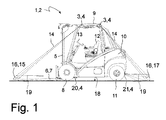
- the Fig. 1 shows a side view of a schematic illustration of an industrial truck 1 according to the invention, here for example a counterbalance forklift 2, with a first, front mounted lighting device 3 and a rear mounted second lighting device 3, each in the form of a laser. 4
- the counterbalance forklift 2 has a guided on a mast 5 load handling device 6 in the form of a fork formed by two forks 7.
- the mast 5 is above a front axle with front wheels. 8 arranged over which the counterbalance forklift 2 is driven.
- Behind the mast 5 is a driver's roof 9 and a counterweight 10.
- Below the counterweight 10 are steered rear wheels 11, with which the counterbalance forklift 2 is directed.
- a driver's seat 12 is arranged with a steering wheel 13.
- the first, front lighting device 3, as well as the second, rear lighting device 3 are preferably arranged on the driver's roof 9 in the upper area and send laser light 14 of the respective laser 4 or bundled light of a light source, such as light emitting diodes, as a light effect, through the one Projection surface 16 is projected onto the roadway 18, wherein the projection surface 16 has a front warning area 15 and a rear warning area 17.
- the projection surface 16 or the front warning area 15 as well as the rear warning area 17 can be marked by a boundary line 19 being marked by light.
- the entire area of the projection surface 16 can also be illuminated, wherein it is also possible to increase the intensity of the light with increasing proximity to the industrial truck 1.
- Another lighting device 20 is mounted in the area of the front vehicle floor and illuminates in the front warning areas 15. Likewise, in the rear lower area of the counterweight 10, a further lighting device 21 is arranged, which lights up in the rear warning areas 17. These further lighting devices 20, 21 may be provided on the driver's safety roof 9 in addition to or as an alternative to the lighting devices 3. It is also possible to illuminate areas in the front warning area 15 or rear warning area 17 of the projection area 16, which are otherwise shaded by parts of the lifting mast 5 or of the counterweight 10th
- the invention is not limited to the example described here of a counterbalance forklift truck 2 as an industrial truck 1 and can be applied to all types of industrial trucks
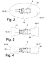
- the Fig. 2 schematically shows the truck of Fig. 1 with a first embodiment of the projection surface 16 in the form of an ellipse 22, which completely surrounds the forklift 2.
- the ellipse 22 is shaped so long stretched, that results in front of the forklift 2, the front warning area 15 and behind the forklift 2, the rear warning area 17.
- the projection surface is also located laterally of the forklift 2.
- the Fig. 3 schematically shows the truck of Fig. 1 with a second embodiment of the projection surface 16, in which the front warning area 15 consists of a trapezoid 23 whose base line corresponds to the width of the forklift 2 and which widened further in front of the forklift 2.
- the rear warning surface 17 consists of another trapezoid 23 whose base line also corresponds to the width of the forklift 2 and widened further behind the forklift 2.
- Fig. 4 schematically shows the truck of Fig. 1 with a third embodiment of a projection surface 16, in which the front warning area 15 consists of a rectangle 24 that extends across the width of the forklift 2. Likewise, the rear warning surface 17 consists of a further rectangle 24 which extends across the width of the forklift 2.
- the Fig. 5a shows the embodiment of the Fig. 4 with the projection surface 16 when cornering forward right, as indicated by the arrow.
- the directions "right” and “left” are defined with respect to a vehicle longitudinal axis with a view to the front of the vehicle regardless of a direction of travel.
- the front in the direction of travel of the forklift 2 warning area 15 of the projection surface 16 is to the inside of the curved path, right here, oriented, and consists of an across the width of the truck extending rectangle, the curve inner side line is replaced by a semicircle 25.
- the rear with respect to the direction of travel of the forklift 2 warning area 17 of the projection 16 is oriented to the outside of the curved path, here on the left, and consists of a three-quarter circle 26, wherein the center 27 approximately at the position of the left and thus curve outside, rear corner of the Forklift 2 is located. It can, as soon as the steering angle of the steering wheel 13 in the direction of travel forward exceeds a certain value, the projection surface 16 from the representation in the Fig. 4 in the form of the Fig. 5a being transformed.
- the Fig. 5b shows the embodiment of the Fig. 4 with the projection surface 16 when cornering forward left, as indicated by the arrow.
- the in the direction of travel of the Forklift 2 front warning area 15 of the projection surface 16 is oriented to the inside of the curved path, here on the left, and consists of a rectangle extending over the width of the truck, the curve-inner side line is replaced by a semicircle 25.
- the rear with respect to the direction of travel of the forklift 2 warning area 17 of the projection 16 is oriented to the outside of the curved path, here right, and in turn consists of a three-quarter circle 26, wherein its center 27 is approximately at the position of the right and thus curve outside, rear corner of the forklift 2 is located.
- the Fig. 5c shows the embodiment of the Fig. 4 with the projection surface 16 when cornering backward right, as indicated by the arrow.
- the front in the direction of travel of the forklift 2 and formed of rectangle and semicircle 25 warning area 15 of the screen 16 is to the inside of the curved path, right here, oriented.
- the rear in relation to the direction of travel of the forklift 2 warning area 17 of the projection surface 16 in turn consists of a three-quarter circle 26 with the approximate center 27, a front corner of the vehicle in this case foundatorial.
- the Fig. 5d shows the embodiment of the Fig. 4 with the projection surface 16 when cornering backward left, as indicated by the arrow.
- the front in the direction of travel of the forklift 2 and formed of rectangle and semicircle 25 warning area 15 of the projection 16 is to the inside of the curved path, left, oriented.
- the rear in relation to the direction of travel of the forklift 2 warning area 17 of the projection surface 16 in turn consists of a three-quarter circle 26, the center 27 is located approximately at the position of the right and thus curve outside, front corner of the forklift 2.
Landscapes
- Engineering & Computer Science (AREA)
- Mechanical Engineering (AREA)
- Structural Engineering (AREA)
- Life Sciences & Earth Sciences (AREA)
- Geology (AREA)
- Transportation (AREA)
- Civil Engineering (AREA)
- Lighting Device Outwards From Vehicle And Optical Signal (AREA)
- Forklifts And Lifting Vehicles (AREA)
Applications Claiming Priority (1)
| Application Number | Priority Date | Filing Date | Title |
|---|---|---|---|
| DE102013100200.5A DE102013100200A1 (de) | 2013-01-10 | 2013-01-10 | Flurförderzeug mit Warnvorrichtung |
Publications (3)
| Publication Number | Publication Date |
|---|---|
| EP2754584A2 true EP2754584A2 (fr) | 2014-07-16 |
| EP2754584A3 EP2754584A3 (fr) | 2018-04-25 |
| EP2754584B1 EP2754584B1 (fr) | 2021-01-27 |
Family
ID=49916914
Family Applications (1)
| Application Number | Title | Priority Date | Filing Date |
|---|---|---|---|
| EP13199435.2A Active EP2754584B1 (fr) | 2013-01-10 | 2013-12-23 | Chariot de manutention avec dispositif d'alarme |
Country Status (2)
| Country | Link |
|---|---|
| EP (1) | EP2754584B1 (fr) |
| DE (1) | DE102013100200A1 (fr) |
Cited By (5)
| Publication number | Priority date | Publication date | Assignee | Title |
|---|---|---|---|---|
| GB2559048A (en) * | 2017-01-04 | 2018-07-25 | Cmy Holdings Ltd | Safety systems for mobile machinery |
| US10676022B2 (en) | 2017-12-27 | 2020-06-09 | X Development Llc | Visually indicating vehicle caution regions |
| US11110957B2 (en) | 2016-08-26 | 2021-09-07 | Crown Equipment Corporation | Materials handling vehicle obstacle scanning tools |
| US11813979B1 (en) | 2022-11-04 | 2023-11-14 | Mitsubishi Logisnext Co., LTD. | Vehicle approach notification device and picking truck equipped with the device |
| US11820634B2 (en) | 2020-02-21 | 2023-11-21 | Crown Equipment Corporation | Modify vehicle parameter based on vehicle position information |
Families Citing this family (5)
| Publication number | Priority date | Publication date | Assignee | Title |
|---|---|---|---|---|
| KR102053490B1 (ko) * | 2016-12-28 | 2019-12-06 | 주식회사 두산 | 지게차의 조사광 제어장치 |
| DE102017223451B4 (de) * | 2017-12-20 | 2019-08-08 | Audi Ag | Verfahren zum Ausleuchten eines Fahrbahnbereichs durch Projizieren einer Trajektorie sowie Kraftfahrzeug |
| DE102018104986A1 (de) * | 2018-03-05 | 2019-09-05 | Jungheinrich Aktiengesellschaft | Verfahren zum Betreiben eines Flurförderzeugs |
| DE102019130039A1 (de) * | 2019-11-07 | 2021-05-12 | Audi Ag | Verfahren zum Betreiben eines fahrerlosen Transportsystems und fahrerloses Transportsystem |
| JP2024067363A (ja) * | 2022-11-04 | 2024-05-17 | 三菱ロジスネクスト株式会社 | 車両接近報知装置および該装置を備えたピッキングトラック |
Citations (1)
| Publication number | Priority date | Publication date | Assignee | Title |
|---|---|---|---|---|
| DE102006002960A1 (de) | 2006-01-21 | 2007-07-26 | Linde Ag | Flurförderzeug mit einer optischen Warneinrichtung |
Family Cites Families (5)
| Publication number | Priority date | Publication date | Assignee | Title |
|---|---|---|---|---|
| DE10240227B4 (de) * | 2002-08-28 | 2006-04-06 | Daimlerchrysler Ag | Verfahren und Vorrichtung zum Betrieb einer Anzeigeeinrichtung an einer Arbeitsmaschine |
| JP4720764B2 (ja) * | 2006-11-16 | 2011-07-13 | 株式会社デンソー | 前照灯制御装置 |
| DE102009001348A1 (de) * | 2009-03-05 | 2010-09-09 | Robert Bosch Gmbh | Verfahren zum Unterstützen eines Fahrbetriebs eines Kraftfahrzeugs sowie Fahrerassistenzvorrrichtung |
| US9090207B2 (en) * | 2010-05-27 | 2015-07-28 | Boxx Corp. | Two wheeled vehicle with lighting system that generates defined image on riding surface |
| US9230419B2 (en) * | 2010-07-27 | 2016-01-05 | Rite-Hite Holding Corporation | Methods and apparatus to detect and warn proximate entities of interest |
-
2013
- 2013-01-10 DE DE102013100200.5A patent/DE102013100200A1/de not_active Ceased
- 2013-12-23 EP EP13199435.2A patent/EP2754584B1/fr active Active
Patent Citations (1)
| Publication number | Priority date | Publication date | Assignee | Title |
|---|---|---|---|---|
| DE102006002960A1 (de) | 2006-01-21 | 2007-07-26 | Linde Ag | Flurförderzeug mit einer optischen Warneinrichtung |
Cited By (7)
| Publication number | Priority date | Publication date | Assignee | Title |
|---|---|---|---|---|
| US11110957B2 (en) | 2016-08-26 | 2021-09-07 | Crown Equipment Corporation | Materials handling vehicle obstacle scanning tools |
| GB2559048A (en) * | 2017-01-04 | 2018-07-25 | Cmy Holdings Ltd | Safety systems for mobile machinery |
| US10676022B2 (en) | 2017-12-27 | 2020-06-09 | X Development Llc | Visually indicating vehicle caution regions |
| US10875448B2 (en) | 2017-12-27 | 2020-12-29 | X Development Llc | Visually indicating vehicle caution regions |
| US11820634B2 (en) | 2020-02-21 | 2023-11-21 | Crown Equipment Corporation | Modify vehicle parameter based on vehicle position information |
| US11912550B2 (en) | 2020-02-21 | 2024-02-27 | Crown Equipment Corporation | Position assistance system for a materials handling vehicle |
| US11813979B1 (en) | 2022-11-04 | 2023-11-14 | Mitsubishi Logisnext Co., LTD. | Vehicle approach notification device and picking truck equipped with the device |
Also Published As
| Publication number | Publication date |
|---|---|
| DE102013100200A1 (de) | 2014-07-10 |
| EP2754584B1 (fr) | 2021-01-27 |
| EP2754584A3 (fr) | 2018-04-25 |
Similar Documents
| Publication | Publication Date | Title |
|---|---|---|
| EP2754584B1 (fr) | Chariot de manutention avec dispositif d'alarme | |
| EP2692687B1 (fr) | Dispositif d'assistance à la conduite et chariot de manutention doté d'un dispositif d'assistance à la conduite | |
| EP2700612B1 (fr) | Chariot de manutention comprenant un dispositif d'avertissement | |
| EP2692688B1 (fr) | Dispositif d'assistance à la conduite pour un chariot de manutention et chariot de manutention | |
| DE202017102636U1 (de) | Dachträger zur Zusatzbeleuchtung | |
| EP3279135B1 (fr) | Dispositif d'avertissement pour un chariot de manutention | |
| DE102018206087B4 (de) | Verfahren zur Kommunikation eines Kraftfahrzeugs mit einem Verkehrsteilnehmer sowie Kraftfahrzeug zur Durchführung des Verfahrens | |
| EP3269579A1 (fr) | Procede de fonctionnement d'un systeme d'informations et systeme d'informations | |
| DE102017010906A1 (de) | Positions-Beleuchtungsvorrichtung und Fahrzeug | |
| WO2020200726A1 (fr) | Dispositif lumineux de communication pour véhicules | |
| DE102016004259A1 (de) | Einparkunterstützungssystem | |
| DE102019204790A1 (de) | Vorrichtung zum Erzeugen eines optischen Warnbereichs für ein Flurfahrzeug oder ein Fahrzeug | |
| EP2428399B1 (fr) | Dispositif d'aide à la manoeuvre pour un véhicule utilitaire | |
| DE102013006045A1 (de) | Verfahren zur Steuerung eines Scheinwerfers | |
| DE202021101367U1 (de) | Mehrlicht-Warnvorrichtung für das Abbiegen eines Kraftfahrzeugs | |
| DE102007000371A1 (de) | Fahrzeugbeleuchtungssystem zum Ermöglichen eines Wahrnehmens eines Vorhandenseins eines Fahrzeugs bezüglich dessen Seitenrichtung | |
| DE102016101404A1 (de) | Warnvorrichtung für ein Flurförderzeug | |
| DE202015104171U1 (de) | Warnvorrichtung für ein Flurförderzeug | |
| DE102015225054B4 (de) | Hubladebühne für Fahrzeuge | |
| DE10306108A1 (de) | Kraftfahrzeug | |
| EP3210932B1 (fr) | Chariot de manutention doté d'un éclairage | |
| DE102012107973A1 (de) | Verfahren zur Personenwarnung bei Flurförderzeugen | |
| DE102019203987A1 (de) | Beleuchtungsanordnung für Fahrzeuge | |
| DE202006001194U1 (de) | Warnschild | |
| EP3569564A1 (fr) | Chariot de manutention pourvu de gyrophare |
Legal Events
| Date | Code | Title | Description |
|---|---|---|---|
| PUAI | Public reference made under article 153(3) epc to a published international application that has entered the european phase |
Free format text: ORIGINAL CODE: 0009012 |
|
| 17P | Request for examination filed |
Effective date: 20131223 |
|
| AK | Designated contracting states |
Kind code of ref document: A2 Designated state(s): AL AT BE BG CH CY CZ DE DK EE ES FI FR GB GR HR HU IE IS IT LI LT LU LV MC MK MT NL NO PL PT RO RS SE SI SK SM TR |
|
| AX | Request for extension of the european patent |
Extension state: BA ME |
|
| PUAL | Search report despatched |
Free format text: ORIGINAL CODE: 0009013 |
|
| RIC1 | Information provided on ipc code assigned before grant |
Ipc: B66F 17/00 20060101ALI20180315BHEP Ipc: B60Q 1/50 20060101AFI20180315BHEP |
|
| AK | Designated contracting states |
Kind code of ref document: A3 Designated state(s): AL AT BE BG CH CY CZ DE DK EE ES FI FR GB GR HR HU IE IS IT LI LT LU LV MC MK MT NL NO PL PT RO RS SE SI SK SM TR |
|
| AX | Request for extension of the european patent |
Extension state: BA ME |
|
| STAA | Information on the status of an ep patent application or granted ep patent |
Free format text: STATUS: REQUEST FOR EXAMINATION WAS MADE |
|
| R17P | Request for examination filed (corrected) |
Effective date: 20181022 |
|
| RBV | Designated contracting states (corrected) |
Designated state(s): AL AT BE BG CH CY CZ DE DK EE ES FI FR GB GR HR HU IE IS IT LI LT LU LV MC MK MT NL NO PL PT RO RS SE SI SK SM TR |
|
| RIC1 | Information provided on ipc code assigned before grant |
Ipc: B66F 9/075 20060101ALI20200807BHEP Ipc: B60Q 1/50 20060101AFI20200807BHEP Ipc: B66F 17/00 20060101ALI20200807BHEP |
|
| GRAP | Despatch of communication of intention to grant a patent |
Free format text: ORIGINAL CODE: EPIDOSNIGR1 |
|
| STAA | Information on the status of an ep patent application or granted ep patent |
Free format text: STATUS: GRANT OF PATENT IS INTENDED |
|
| INTG | Intention to grant announced |
Effective date: 20201001 |
|
| GRAS | Grant fee paid |
Free format text: ORIGINAL CODE: EPIDOSNIGR3 |
|
| GRAA | (expected) grant |
Free format text: ORIGINAL CODE: 0009210 |
|
| STAA | Information on the status of an ep patent application or granted ep patent |
Free format text: STATUS: THE PATENT HAS BEEN GRANTED |
|
| AK | Designated contracting states |
Kind code of ref document: B1 Designated state(s): AL AT BE BG CH CY CZ DE DK EE ES FI FR GB GR HR HU IE IS IT LI LT LU LV MC MK MT NL NO PL PT RO RS SE SI SK SM TR |
|
| REG | Reference to a national code |
Ref country code: GB Ref legal event code: FG4D Free format text: NOT ENGLISH |
|
| REG | Reference to a national code |
Ref country code: CH Ref legal event code: EP |
|
| REG | Reference to a national code |
Ref country code: AT Ref legal event code: REF Ref document number: 1358060 Country of ref document: AT Kind code of ref document: T Effective date: 20210215 |
|
| REG | Reference to a national code |
Ref country code: IE Ref legal event code: FG4D Free format text: LANGUAGE OF EP DOCUMENT: GERMAN |
|
| REG | Reference to a national code |
Ref country code: DE Ref legal event code: R096 Ref document number: 502013015472 Country of ref document: DE |
|
| REG | Reference to a national code |
Ref country code: NL Ref legal event code: MP Effective date: 20210127 |
|
| REG | Reference to a national code |
Ref country code: LT Ref legal event code: MG9D |
|
| PG25 | Lapsed in a contracting state [announced via postgrant information from national office to epo] |
Ref country code: LT Free format text: LAPSE BECAUSE OF FAILURE TO SUBMIT A TRANSLATION OF THE DESCRIPTION OR TO PAY THE FEE WITHIN THE PRESCRIBED TIME-LIMIT Effective date: 20210127 Ref country code: PT Free format text: LAPSE BECAUSE OF FAILURE TO SUBMIT A TRANSLATION OF THE DESCRIPTION OR TO PAY THE FEE WITHIN THE PRESCRIBED TIME-LIMIT Effective date: 20210527 Ref country code: FI Free format text: LAPSE BECAUSE OF FAILURE TO SUBMIT A TRANSLATION OF THE DESCRIPTION OR TO PAY THE FEE WITHIN THE PRESCRIBED TIME-LIMIT Effective date: 20210127 Ref country code: HR Free format text: LAPSE BECAUSE OF FAILURE TO SUBMIT A TRANSLATION OF THE DESCRIPTION OR TO PAY THE FEE WITHIN THE PRESCRIBED TIME-LIMIT Effective date: 20210127 Ref country code: GR Free format text: LAPSE BECAUSE OF FAILURE TO SUBMIT A TRANSLATION OF THE DESCRIPTION OR TO PAY THE FEE WITHIN THE PRESCRIBED TIME-LIMIT Effective date: 20210428 Ref country code: BG Free format text: LAPSE BECAUSE OF FAILURE TO SUBMIT A TRANSLATION OF THE DESCRIPTION OR TO PAY THE FEE WITHIN THE PRESCRIBED TIME-LIMIT Effective date: 20210427 Ref country code: NL Free format text: LAPSE BECAUSE OF FAILURE TO SUBMIT A TRANSLATION OF THE DESCRIPTION OR TO PAY THE FEE WITHIN THE PRESCRIBED TIME-LIMIT Effective date: 20210127 Ref country code: NO Free format text: LAPSE BECAUSE OF FAILURE TO SUBMIT A TRANSLATION OF THE DESCRIPTION OR TO PAY THE FEE WITHIN THE PRESCRIBED TIME-LIMIT Effective date: 20210427 |
|
| PG25 | Lapsed in a contracting state [announced via postgrant information from national office to epo] |
Ref country code: SE Free format text: LAPSE BECAUSE OF FAILURE TO SUBMIT A TRANSLATION OF THE DESCRIPTION OR TO PAY THE FEE WITHIN THE PRESCRIBED TIME-LIMIT Effective date: 20210127 Ref country code: PL Free format text: LAPSE BECAUSE OF FAILURE TO SUBMIT A TRANSLATION OF THE DESCRIPTION OR TO PAY THE FEE WITHIN THE PRESCRIBED TIME-LIMIT Effective date: 20210127 Ref country code: LV Free format text: LAPSE BECAUSE OF FAILURE TO SUBMIT A TRANSLATION OF THE DESCRIPTION OR TO PAY THE FEE WITHIN THE PRESCRIBED TIME-LIMIT Effective date: 20210127 Ref country code: RS Free format text: LAPSE BECAUSE OF FAILURE TO SUBMIT A TRANSLATION OF THE DESCRIPTION OR TO PAY THE FEE WITHIN THE PRESCRIBED TIME-LIMIT Effective date: 20210127 |
|
| PG25 | Lapsed in a contracting state [announced via postgrant information from national office to epo] |
Ref country code: IS Free format text: LAPSE BECAUSE OF FAILURE TO SUBMIT A TRANSLATION OF THE DESCRIPTION OR TO PAY THE FEE WITHIN THE PRESCRIBED TIME-LIMIT Effective date: 20210527 |
|
| REG | Reference to a national code |
Ref country code: DE Ref legal event code: R097 Ref document number: 502013015472 Country of ref document: DE |
|
| PG25 | Lapsed in a contracting state [announced via postgrant information from national office to epo] |
Ref country code: SM Free format text: LAPSE BECAUSE OF FAILURE TO SUBMIT A TRANSLATION OF THE DESCRIPTION OR TO PAY THE FEE WITHIN THE PRESCRIBED TIME-LIMIT Effective date: 20210127 Ref country code: CZ Free format text: LAPSE BECAUSE OF FAILURE TO SUBMIT A TRANSLATION OF THE DESCRIPTION OR TO PAY THE FEE WITHIN THE PRESCRIBED TIME-LIMIT Effective date: 20210127 Ref country code: EE Free format text: LAPSE BECAUSE OF FAILURE TO SUBMIT A TRANSLATION OF THE DESCRIPTION OR TO PAY THE FEE WITHIN THE PRESCRIBED TIME-LIMIT Effective date: 20210127 |
|
| PG25 | Lapsed in a contracting state [announced via postgrant information from national office to epo] |
Ref country code: RO Free format text: LAPSE BECAUSE OF FAILURE TO SUBMIT A TRANSLATION OF THE DESCRIPTION OR TO PAY THE FEE WITHIN THE PRESCRIBED TIME-LIMIT Effective date: 20210127 Ref country code: SK Free format text: LAPSE BECAUSE OF FAILURE TO SUBMIT A TRANSLATION OF THE DESCRIPTION OR TO PAY THE FEE WITHIN THE PRESCRIBED TIME-LIMIT Effective date: 20210127 Ref country code: ES Free format text: LAPSE BECAUSE OF FAILURE TO SUBMIT A TRANSLATION OF THE DESCRIPTION OR TO PAY THE FEE WITHIN THE PRESCRIBED TIME-LIMIT Effective date: 20210127 Ref country code: DK Free format text: LAPSE BECAUSE OF FAILURE TO SUBMIT A TRANSLATION OF THE DESCRIPTION OR TO PAY THE FEE WITHIN THE PRESCRIBED TIME-LIMIT Effective date: 20210127 |
|
| PLBE | No opposition filed within time limit |
Free format text: ORIGINAL CODE: 0009261 |
|
| STAA | Information on the status of an ep patent application or granted ep patent |
Free format text: STATUS: NO OPPOSITION FILED WITHIN TIME LIMIT |
|
| 26N | No opposition filed |
Effective date: 20211028 |
|
| PG25 | Lapsed in a contracting state [announced via postgrant information from national office to epo] |
Ref country code: AL Free format text: LAPSE BECAUSE OF FAILURE TO SUBMIT A TRANSLATION OF THE DESCRIPTION OR TO PAY THE FEE WITHIN THE PRESCRIBED TIME-LIMIT Effective date: 20210127 |
|
| PG25 | Lapsed in a contracting state [announced via postgrant information from national office to epo] |
Ref country code: SI Free format text: LAPSE BECAUSE OF FAILURE TO SUBMIT A TRANSLATION OF THE DESCRIPTION OR TO PAY THE FEE WITHIN THE PRESCRIBED TIME-LIMIT Effective date: 20210127 |
|
| PG25 | Lapsed in a contracting state [announced via postgrant information from national office to epo] |
Ref country code: IT Free format text: LAPSE BECAUSE OF FAILURE TO SUBMIT A TRANSLATION OF THE DESCRIPTION OR TO PAY THE FEE WITHIN THE PRESCRIBED TIME-LIMIT Effective date: 20210127 |
|
| PG25 | Lapsed in a contracting state [announced via postgrant information from national office to epo] |
Ref country code: IS Free format text: LAPSE BECAUSE OF FAILURE TO SUBMIT A TRANSLATION OF THE DESCRIPTION OR TO PAY THE FEE WITHIN THE PRESCRIBED TIME-LIMIT Effective date: 20210527 |
|
| PG25 | Lapsed in a contracting state [announced via postgrant information from national office to epo] |
Ref country code: MC Free format text: LAPSE BECAUSE OF FAILURE TO SUBMIT A TRANSLATION OF THE DESCRIPTION OR TO PAY THE FEE WITHIN THE PRESCRIBED TIME-LIMIT Effective date: 20210127 |
|
| REG | Reference to a national code |
Ref country code: CH Ref legal event code: PL |
|
| REG | Reference to a national code |
Ref country code: BE Ref legal event code: MM Effective date: 20211231 |
|
| PG25 | Lapsed in a contracting state [announced via postgrant information from national office to epo] |
Ref country code: LU Free format text: LAPSE BECAUSE OF NON-PAYMENT OF DUE FEES Effective date: 20211223 Ref country code: IE Free format text: LAPSE BECAUSE OF NON-PAYMENT OF DUE FEES Effective date: 20211223 |
|
| PG25 | Lapsed in a contracting state [announced via postgrant information from national office to epo] |
Ref country code: BE Free format text: LAPSE BECAUSE OF NON-PAYMENT OF DUE FEES Effective date: 20211231 |
|
| PG25 | Lapsed in a contracting state [announced via postgrant information from national office to epo] |
Ref country code: LI Free format text: LAPSE BECAUSE OF NON-PAYMENT OF DUE FEES Effective date: 20211231 Ref country code: CH Free format text: LAPSE BECAUSE OF NON-PAYMENT OF DUE FEES Effective date: 20211231 |
|
| REG | Reference to a national code |
Ref country code: AT Ref legal event code: MM01 Ref document number: 1358060 Country of ref document: AT Kind code of ref document: T Effective date: 20211223 |
|
| PG25 | Lapsed in a contracting state [announced via postgrant information from national office to epo] |
Ref country code: AT Free format text: LAPSE BECAUSE OF NON-PAYMENT OF DUE FEES Effective date: 20211223 |
|
| PG25 | Lapsed in a contracting state [announced via postgrant information from national office to epo] |
Ref country code: HU Free format text: LAPSE BECAUSE OF FAILURE TO SUBMIT A TRANSLATION OF THE DESCRIPTION OR TO PAY THE FEE WITHIN THE PRESCRIBED TIME-LIMIT; INVALID AB INITIO Effective date: 20131223 |
|
| P01 | Opt-out of the competence of the unified patent court (upc) registered |
Effective date: 20230507 |
|
| PG25 | Lapsed in a contracting state [announced via postgrant information from national office to epo] |
Ref country code: CY Free format text: LAPSE BECAUSE OF FAILURE TO SUBMIT A TRANSLATION OF THE DESCRIPTION OR TO PAY THE FEE WITHIN THE PRESCRIBED TIME-LIMIT Effective date: 20210127 |
|
| PGFP | Annual fee paid to national office [announced via postgrant information from national office to epo] |
Ref country code: GB Payment date: 20231220 Year of fee payment: 11 |
|
| PGFP | Annual fee paid to national office [announced via postgrant information from national office to epo] |
Ref country code: FR Payment date: 20231220 Year of fee payment: 11 Ref country code: DE Payment date: 20231214 Year of fee payment: 11 |
|
| PG25 | Lapsed in a contracting state [announced via postgrant information from national office to epo] |
Ref country code: MK Free format text: LAPSE BECAUSE OF FAILURE TO SUBMIT A TRANSLATION OF THE DESCRIPTION OR TO PAY THE FEE WITHIN THE PRESCRIBED TIME-LIMIT Effective date: 20210127 |