EP2753203B2 - Heating smokable material - Google Patents
Heating smokable material Download PDFInfo
- Publication number
- EP2753203B2 EP2753203B2 EP12750771.3A EP12750771A EP2753203B2 EP 2753203 B2 EP2753203 B2 EP 2753203B2 EP 12750771 A EP12750771 A EP 12750771A EP 2753203 B2 EP2753203 B2 EP 2753203B2
- Authority
- EP
- European Patent Office
- Prior art keywords
- smokable material
- heating
- heater
- region
- heat
- Prior art date
- Legal status (The legal status is an assumption and is not a legal conclusion. Google has not performed a legal analysis and makes no representation as to the accuracy of the status listed.)
- Active
Links
- 238000010438 heat treatment Methods 0.000 title claims description 230
- 239000000463 material Substances 0.000 title claims description 204
- 238000009833 condensation Methods 0.000 claims description 7
- 230000005494 condensation Effects 0.000 claims description 7
- 238000000034 method Methods 0.000 claims description 6
- 238000009413 insulation Methods 0.000 description 46
- 230000004913 activation Effects 0.000 description 24
- 230000004044 response Effects 0.000 description 16
- SNICXCGAKADSCV-JTQLQIEISA-N (-)-Nicotine Chemical compound CN1CCC[C@H]1C1=CC=CN=C1 SNICXCGAKADSCV-JTQLQIEISA-N 0.000 description 14
- 229960002715 nicotine Drugs 0.000 description 14
- SNICXCGAKADSCV-UHFFFAOYSA-N nicotine Natural products CN1CCCC1C1=CC=CN=C1 SNICXCGAKADSCV-UHFFFAOYSA-N 0.000 description 14
- 241000208125 Nicotiana Species 0.000 description 12
- 235000002637 Nicotiana tabacum Nutrition 0.000 description 12
- 150000001491 aromatic compounds Chemical class 0.000 description 10
- 230000003213 activating effect Effects 0.000 description 8
- 239000000919 ceramic Substances 0.000 description 7
- 239000011248 coating agent Substances 0.000 description 6
- 238000000576 coating method Methods 0.000 description 6
- 150000001875 compounds Chemical class 0.000 description 5
- 238000001514 detection method Methods 0.000 description 5
- 230000000694 effects Effects 0.000 description 4
- 230000001007 puffing effect Effects 0.000 description 4
- 230000009467 reduction Effects 0.000 description 4
- 239000000796 flavoring agent Substances 0.000 description 3
- 235000019634 flavors Nutrition 0.000 description 3
- 230000010354 integration Effects 0.000 description 3
- 230000000391 smoking effect Effects 0.000 description 3
- 239000007787 solid Substances 0.000 description 3
- 239000000126 substance Substances 0.000 description 3
- 239000007789 gas Substances 0.000 description 2
- 239000000779 smoke Substances 0.000 description 2
- 229910001220 stainless steel Inorganic materials 0.000 description 2
- 239000010935 stainless steel Substances 0.000 description 2
- 239000000758 substrate Substances 0.000 description 2
- 229910052581 Si3N4 Inorganic materials 0.000 description 1
- GWEVSGVZZGPLCZ-UHFFFAOYSA-N Titan oxide Chemical compound O=[Ti]=O GWEVSGVZZGPLCZ-UHFFFAOYSA-N 0.000 description 1
- 239000004964 aerogel Substances 0.000 description 1
- 239000004411 aluminium Substances 0.000 description 1
- XAGFODPZIPBFFR-UHFFFAOYSA-N aluminium Chemical compound [Al] XAGFODPZIPBFFR-UHFFFAOYSA-N 0.000 description 1
- 229910052782 aluminium Inorganic materials 0.000 description 1
- PNEYBMLMFCGWSK-UHFFFAOYSA-N aluminium oxide Inorganic materials [O-2].[O-2].[O-2].[Al+3].[Al+3] PNEYBMLMFCGWSK-UHFFFAOYSA-N 0.000 description 1
- QVGXLLKOCUKJST-UHFFFAOYSA-N atomic oxygen Chemical compound [O] QVGXLLKOCUKJST-UHFFFAOYSA-N 0.000 description 1
- 230000008901 benefit Effects 0.000 description 1
- 239000003990 capacitor Substances 0.000 description 1
- 235000019506 cigar Nutrition 0.000 description 1
- 235000019504 cigarettes Nutrition 0.000 description 1
- 238000004891 communication Methods 0.000 description 1
- 230000008878 coupling Effects 0.000 description 1
- 238000010168 coupling process Methods 0.000 description 1
- 238000005859 coupling reaction Methods 0.000 description 1
- 230000007423 decrease Effects 0.000 description 1
- 238000010586 diagram Methods 0.000 description 1
- 230000005670 electromagnetic radiation Effects 0.000 description 1
- 229910001416 lithium ion Inorganic materials 0.000 description 1
- 230000007246 mechanism Effects 0.000 description 1
- 239000012528 membrane Substances 0.000 description 1
- 239000007769 metal material Substances 0.000 description 1
- 239000000203 mixture Substances 0.000 description 1
- 239000001301 oxygen Substances 0.000 description 1
- 229910052760 oxygen Inorganic materials 0.000 description 1
- 229920000642 polymer Polymers 0.000 description 1
- 239000011148 porous material Substances 0.000 description 1
- 238000002360 preparation method Methods 0.000 description 1
- 230000001902 propagating effect Effects 0.000 description 1
- 230000005855 radiation Effects 0.000 description 1
- 229920006395 saturated elastomer Polymers 0.000 description 1
- HQVNEWCFYHHQES-UHFFFAOYSA-N silicon nitride Chemical compound N12[Si]34N5[Si]62N3[Si]51N64 HQVNEWCFYHHQES-UHFFFAOYSA-N 0.000 description 1
- OGIDPMRJRNCKJF-UHFFFAOYSA-N titanium oxide Inorganic materials [Ti]=O OGIDPMRJRNCKJF-UHFFFAOYSA-N 0.000 description 1
- 230000001960 triggered effect Effects 0.000 description 1
- 238000011144 upstream manufacturing Methods 0.000 description 1
- 238000010792 warming Methods 0.000 description 1
Images


Classifications
-
- A—HUMAN NECESSITIES
- A24—TOBACCO; CIGARS; CIGARETTES; SIMULATED SMOKING DEVICES; SMOKERS' REQUISITES
- A24F—SMOKERS' REQUISITES; MATCH BOXES; SIMULATED SMOKING DEVICES
- A24F40/00—Electrically operated smoking devices; Component parts thereof; Manufacture thereof; Maintenance or testing thereof; Charging means specially adapted therefor
- A24F40/40—Constructional details, e.g. connection of cartridges and battery parts
- A24F40/46—Shape or structure of electric heating means
-
- A—HUMAN NECESSITIES
- A24—TOBACCO; CIGARS; CIGARETTES; SIMULATED SMOKING DEVICES; SMOKERS' REQUISITES
- A24F—SMOKERS' REQUISITES; MATCH BOXES; SIMULATED SMOKING DEVICES
- A24F1/00—Tobacco pipes
- A24F1/28—Tubular pipes, e.g. in the form of cigars
-
- A—HUMAN NECESSITIES
- A24—TOBACCO; CIGARS; CIGARETTES; SIMULATED SMOKING DEVICES; SMOKERS' REQUISITES
- A24F—SMOKERS' REQUISITES; MATCH BOXES; SIMULATED SMOKING DEVICES
- A24F40/00—Electrically operated smoking devices; Component parts thereof; Manufacture thereof; Maintenance or testing thereof; Charging means specially adapted therefor
- A24F40/20—Devices using solid inhalable precursors
-
- A—HUMAN NECESSITIES
- A24—TOBACCO; CIGARS; CIGARETTES; SIMULATED SMOKING DEVICES; SMOKERS' REQUISITES
- A24F—SMOKERS' REQUISITES; MATCH BOXES; SIMULATED SMOKING DEVICES
- A24F40/00—Electrically operated smoking devices; Component parts thereof; Manufacture thereof; Maintenance or testing thereof; Charging means specially adapted therefor
- A24F40/50—Control or monitoring
- A24F40/57—Temperature control
-
- H—ELECTRICITY
- H05—ELECTRIC TECHNIQUES NOT OTHERWISE PROVIDED FOR
- H05B—ELECTRIC HEATING; ELECTRIC LIGHT SOURCES NOT OTHERWISE PROVIDED FOR; CIRCUIT ARRANGEMENTS FOR ELECTRIC LIGHT SOURCES, IN GENERAL
- H05B1/00—Details of electric heating devices
- H05B1/02—Automatic switching arrangements specially adapted to apparatus ; Control of heating devices
- H05B1/0227—Applications
- H05B1/0252—Domestic applications
-
- H—ELECTRICITY
- H05—ELECTRIC TECHNIQUES NOT OTHERWISE PROVIDED FOR
- H05B—ELECTRIC HEATING; ELECTRIC LIGHT SOURCES NOT OTHERWISE PROVIDED FOR; CIRCUIT ARRANGEMENTS FOR ELECTRIC LIGHT SOURCES, IN GENERAL
- H05B3/00—Ohmic-resistance heating
- H05B3/10—Heater elements characterised by the composition or nature of the materials or by the arrangement of the conductor
- H05B3/12—Heater elements characterised by the composition or nature of the materials or by the arrangement of the conductor characterised by the composition or nature of the conductive material
- H05B3/14—Heater elements characterised by the composition or nature of the materials or by the arrangement of the conductor characterised by the composition or nature of the conductive material the material being non-metallic
- H05B3/141—Conductive ceramics, e.g. metal oxides, metal carbides, barium titanate, ferrites, zirconia, vitrous compounds
-
- H—ELECTRICITY
- H05—ELECTRIC TECHNIQUES NOT OTHERWISE PROVIDED FOR
- H05B—ELECTRIC HEATING; ELECTRIC LIGHT SOURCES NOT OTHERWISE PROVIDED FOR; CIRCUIT ARRANGEMENTS FOR ELECTRIC LIGHT SOURCES, IN GENERAL
- H05B3/00—Ohmic-resistance heating
- H05B3/40—Heating elements having the shape of rods or tubes
- H05B3/42—Heating elements having the shape of rods or tubes non-flexible
- H05B3/44—Heating elements having the shape of rods or tubes non-flexible heating conductor arranged within rods or tubes of insulating material
-
- A—HUMAN NECESSITIES
- A24—TOBACCO; CIGARS; CIGARETTES; SIMULATED SMOKING DEVICES; SMOKERS' REQUISITES
- A24D—CIGARS; CIGARETTES; TOBACCO SMOKE FILTERS; MOUTHPIECES FOR CIGARS OR CIGARETTES; MANUFACTURE OF TOBACCO SMOKE FILTERS OR MOUTHPIECES
- A24D1/00—Cigars; Cigarettes
- A24D1/20—Cigarettes specially adapted for simulated smoking devices
-
- A—HUMAN NECESSITIES
- A24—TOBACCO; CIGARS; CIGARETTES; SIMULATED SMOKING DEVICES; SMOKERS' REQUISITES
- A24F—SMOKERS' REQUISITES; MATCH BOXES; SIMULATED SMOKING DEVICES
- A24F47/00—Smokers' requisites not otherwise provided for
Definitions
- Smoking articles such as cigarettes and cigars burn tobacco during use to create tobacco smoke. Attempts have been made to provide alternatives to these smoking articles by creating products which release compounds without creating tobacco smoke. Examples of such products are so-called heat-not-burn products which release compounds by heating, but not burning, tobacco.
- EP2327318 describes an electrically heated smoking system for receiving an aerosol-forming substrate, wherein a heating element extends a distance only partially along the length of the received aerosol-forming substrate.
- the apparatus may be configured to cause a third heating region to heat a third region of smokable material to said volatizing temperature and to cause the first and/or second heating region(s) to heat the first and/or second regions of smokable material to said lower temperature.
- the lower temperature may prevent condensation of volatized components in the heating chamber.
- the volatizing temperature may be 100 degrees Celsius or higher.
- the lower temperature may be less than 100 degrees Celsius.
- the term 'smokable material' includes any material that provides volatilized components upon heating and includes any tobacco-containing material and may, for example, include one or more of tobacco, tobacco derivatives, expanded tobacco, reconstituted tobacco or tobacco substitutes.
- An apparatus 1 for heating smokable material comprises an energy source 2, a heater 3 and a heating chamber 4.
- the energy source 2 may comprise a battery such as a Li-ion battery, Ni battery, Alkaline battery and/or the like, and is electrically coupled to the heater 3 to supply electrical energy to the heater 3 when required.
- the heating chamber 4 is configured to receive smokable material 5 so that the smokable material 5 can be heated in the heating chamber 4.
- the heating chamber 4 is located adjacent to the heater 3 so that thermal energy from the heater 3 heats the smokable material 5 therein to volatilize aromatic compounds and nicotine in the smokable material 5, without burning the smokable material 5.
- a mouthpiece 6 is provided through which a user of the apparatus 1 can inhale the volatilized compounds during use of the apparatus 1.
- the smokable material 5 may comprise a tobacco blend.
- the heater 3 may comprise a substantially cylindrical, elongate heater 3 and the heating chamber 4 may be located either outwardly or inwardly of a longitudinal external surface of the heater 3.
- the heating chamber 4 may be located around the outside of a circumferential, longitudinal surface of the heater 3.
- the heating chamber 4 and smokable material 5 may therefore comprise co-axial layers around the heater 3.
- the heating chamber 4 may be located internally of the longitudinal surface of the heater 3 so that the heating chamber 4 comprises a core or other cavity internal of the heating surface.
- other shapes and configurations of the heater 3 and heating chamber 4 can alternatively be used.
- a housing 7 may contain components of the apparatus 1 such as the energy source 2 and heater 3.
- the housing 7 may comprise an approximately cylindrical tube with the energy source 2 located towards its first end 8 and the heater 3 and heating chamber 4 located towards its opposite, second end 9.
- the energy source 2 and heater 3 extend along the longitudinal axis of the housing 7.
- the energy source 2 and heater 3 can be aligned along the central longitudinal axis of the housing 7 in a substantially end-to-end arrangement so that an end face of the energy source 2 substantially faces an end face of the heater 3.
- Heat insulation may be provided between the energy source 2 and the heater 3 to prevent direct transfer of heat from one to the other.
- the length of the housing 7 may be approximately 130mm, the length of the energy source may be approximately 59mm, and the length of the heater 3 and heating region 4 may be approximately 50mm.
- the diameter of the housing 7 may be between approximately 9mm and approximately 18mm.
- the diameter of the housing's first end 8 may be between 15mm and 18mm whilst the diameter of the mouthpiece 6 at the housing's second end 9 may between 9mm and 15mm.
- the diameter of the heater 3 may be between approximately 2.0mm and approximately 13-0mm, depending on the heater configuration.
- a heating chamber 4 located outwardly of the heater 3, such as that shown in figure 1 may have an exterior diameter of approximately 10mm at its outwardly-facing surface whilst a heating chamber 4 located inwardly of the heater 3, such as that shown in figure 2 , may have a diameter of between approximately 5mm and approximately 8.0mm such as between approximately 3.0mm and approximately 6.0mm.
- the diameter of the energy source 2 may be between approximately 14.0mm and approximately 15.0mm, such as 14.6mm although other diameters of energy source 2 could equally be used.
- the mouthpiece 6 can be located at the second end 9 of the housing 7, adjacent the heating chamber 4 and smokable material 5.
- the housing 7 is suitable for being gripped by a user during use of the apparatus 1 so that the user can inhale volatilized smokable material compounds from the mouthpiece 6 of the apparatus 1.
- the heater 3 may comprise a ceramics heater 3, examples of which are shown in figures 1 to 4 .
- the ceramics heater 3 may, for example, comprise base ceramics of alumina and/or silicon nitride which are laminated and sintered.
- the heater 3 may comprise an infra-red (IR) heater 3 such as a halogen-IR lamp 3.
- IR infra-red
- the IR heater 3 may have a low mass and therefore its use can help to reduce the overall mass of the apparatus 1.
- the mass of the IR heater may be 20% to 30% less than the mass of a ceramics heater 3 having an equivalent heating power output.
- the IR heater 3 also has low thermal inertia and therefore is able to heat the smokable material 5 very rapidly in response to an activation stimulus.
- the IR heater 3 may be configured to emit IR electromagnetic radiation of between approximately 700nm and 4.5 ⁇ m in wavelength.
- a resistive heater 3 such as a resistive wire wound on a ceramic insulation layer deposited on a wall of the thermal insulation 18 referred to further below.
- the heater 3 may be located in a central region of the housing 7 and the heating chamber 4 and smokable material 5 may be located around the longitudinal surface of the heater 3. In this arrangement, thermal energy emitted by the heater 3 may travel in a radial direction outwards from the longitudinal surface of the heater 3 into the heating chamber 4 and the smokable material 5.
- the heater 3 may be located towards the periphery of the housing 7 and the heating chamber 4 and smokable material 5 may be located in a central region of the housing 7 which is internal from the longitudinal surface of the heater 3. In this arrangement, thermal energy emitted by the heater 3 travels in a radial direction inwards from a longitudinal surface of the heater 3 into the heating chamber 4 and the smokable material 5.
- the heater 3 comprises a plurality of individual heating regions 10, as shown in figures 2 and 3 .
- the heating regions 10 are operable independently of one another so that different regions 10 can be activated at different times to heat the smokable material 5.
- the heating regions 10 may be arranged in the heater 3 in any geometric arrangement. However, in the examples shown in the figures, the heating regions 10 are geometrically arranged in the heater 3 so that different ones of the heating regions 10 are arranged to predominately and independently heat different regions of the smokable material 5.
- the heater 3 may comprise a plurality of axially aligned heating regions 10 in a substantially elongate arrangement.
- the regions 10 may each comprise an individual element of the heater 3.
- the heating regions 10 may, for example, all be aligned with each other along a longitudinal axis of the heater 3, thus providing a plurality of independent heating zones along the length of the heater 3.
- Each heating region 10 may comprise a heating cylinder 10 having a finite length which is significantly less than the length of the heater 3 as a whole.
- the cylinders 10 may comprise solid disks where each disk has a depth equivalent to the cylinder length referred to above. An example of this is shown in figure 3 .
- the cylinders 10 may comprise hollow rings, an example of which is shown in figure 2 .
- the arrangement of axially aligned heating regions 10 define the exterior of the heating chamber 4 and are configured to apply heat inwardly, predominately towards the central longitudinal axis of the chamber 4.
- the heating regions 10 are arranged with their radial, or otherwise transverse, surfaces facing one another along the length of the heater 3.
- the transverse surfaces of each region 10 may touch the transverse surfaces of its neighbouring regions 10.
- the transverse surfaces of each region 10 may be separated from the transverse surfaces of its neighbouring region(s) 10. Thermal insulation 18 may be present between such separated heating regions 10, as discussed in more detail below. An example of this is shown in figure 2 .
- the heated region of smokable material 5 may comprise a ring of smokable material 5 located around the heating region 10 which has been activated.
- the smokable material 5 can therefore be heated in independent sections, for example ring or core sections, where each section corresponds to smokable material 5 located directly inwardly or outwardly of a particular one of the heating regions 10 and has a mass and volume which is significantly less than the body of smokable material 5 as a whole.
- the heater 3 may comprise a plurality of elongate, longitudinally extending heating regions 10 positioned at different locations around the central longitudinal axis of the heater 3.
- the longitudinally extending heating regions 10 may be of substantially the same length so that each extends along substantially the whole length of the heater 3.
- Each heating region 10 may comprise, for example, an individual IR heating element 10 such as an IR heating filament 10.
- a body of heat insulation or heat reflective material may be provided along the central longitudinal axis of the heater 3 so that thermal energy emitted by each heating region 10 travels predominately outwards from the heater 3 into the heating chamber 4 and thus heats the smokable material 5.
- the distance between the central longitudinal axis of the heater 3 and each of the heating regions 10 may be substantially equal.
- the heating regions 10 may optionally be contained in a substantially infra-red and/or heat transparent tube, or other housing, which forms a longitudinal surface of the heater 3.
- the heating regions 10 may be fixed in position relative to the other heating regions 10 inside the tube.
- the heated section of smokable material 5 may comprise a longitudinal section of smokable material 5 which lies parallel and directly adjacent to the longitudinal heating region 10. Therefore, as with the previous examples, the smokable material 5 can be heated in independent sections.
- the heating regions 10 can each be individually and selectively activated.
- the smokable material 5 may be comprised in a cartridge 11 which can be inserted into the heating chamber 4.
- the cartridge 11 can comprise a smokable material tube 11 which can be inserted around the heater 3 so that the internal surface of the smokable material tube 11 faces the longitudinal surface of the heater 3.
- the smokable material tube 11 may be hollow.
- the diameter of the hollow centre of the tube 11 may be substantially equal to, or slightly larger than, the diameter of the heater 3 so that the tube 11 is a close fit around the heater 3.
- the cartridge 11 may comprise a substantially solid rod of smokable material 5 which can be inserted into a heating chamber 4 located inwardly of the heater 3 so that the external longitudinal surface of the rod 11 faces the internal longitudinal surface of the heater 3.
- the length of the cartridge 11 may be approximately equal to the length of the heater 3 so that the heater 3 can heat the cartridge 11 along its whole length.
- the heater 3 comprises a spirally shaped heater 3.
- the spirally shaped heater 3 may be configured to screw into the smokable material cartridge 11 and may comprise adjacent, axially-aligned heating regions 10 so as to operate in substantially the same manner as described for the linear, elongate heater 3 discussed above with reference to figures 1 and 3 .
- the heater 3 can comprise a plurality of heating regions 10 which extend directly into an elongate heating chamber 4 which is divided into sections by the heating regions 10.
- the heating regions 10 extend directly into an elongate smokable material cartridge 11 or other substantially solid body of smokable material 5.
- the smokable material 5 in the heating chamber 4 is thereby divided into discrete sections separated from each other by the spaced-apart heating regions 10.
- the heater 3, heating chamber 4 and smokable material 5 may extend together along a central, longitudinal axis of the housing 7.
- the heating regions 10 may each comprise a projection 10, such as an upstanding heating plate 10, which extends into the body of smokable material 5.
- the projections 10 are discussed below in the context of heating plates 10.
- the principal plane of the heating plates 10 may be substantially perpendicular to the principal longitudinal axis of the body of smokable material 5 and heating chamber 4 and/or housing 7.
- the heating plates 10 may be parallel to one another, as shown in figures 8 and 10 .
- Each section of smokable material 5 is bounded by a main heating surface of a pair of heating plates 10 located either side of the smokable material section, so that activation of one or both of the heating plates 10 will cause thermal energy to be transferred directly into the smokable material 5.
- each heating plate 10 may comprise a thermally reflective layer which divides the plate 10 into two halves along its principal plane.
- Each half of the plate 10 can thus constitute a separate heating region 10 and may be independently activated to heat only the section of smokable material 5 which lies directly against that half of the plate 10, rather than the smokable material 5 on both sides of the plate 10.
- Adjacent plates 10, or facing portions thereof, may be activated to heat a section of smokable material 5, which is located between the adjacent plates, from substantially opposite sides of the section of smokable material 5.
- the elongate smokable material cartridge or body 11 can be installed between, and removed from, the heating chamber 4 and heating plates 10 by removing a section of the housing 7 at the housing's second end 9, as previously described.
- the heating regions 10 can be individually and selectively activated to heat different sections of the smokable material 5 as required.
- the heated section of smokable material 5 may comprise a radial section of smokable material 5 located between the heating regions 10, as shown in figures 8 to 10 .
- the housing 7 of the apparatus 1 may comprise an opening through which the cartridge 11 can be inserted into the heating chamber 4.
- the opening may, for example, comprise an opening located at the housing's second end 9 so that the cartridge 11 can be slid into the opening and pushed directly into the heating chamber 4.
- the opening is preferably closed during use of the apparatus 1 to heat the smokable material 5.
- a section of the housing 7 at the second end 9 is removable from the apparatus 1 so that the smokable material 5 can be inserted into the heating chamber 4.
- An example of this is shown in figure 10 .
- the apparatus 1 may optionally be equipped with a user-operable smokable material ejection unit, such as an internal mechanism configured to slide used smokable material 5 off and/or away from the heater 3.
- the used smokable material 5 may, for example, be pushed back through the opening in the housing 7. A new cartridge 11 can then be inserted as required.
- Thermal insulation 18 may be provided between the smokable material 5 and an external surface 19 of the housing 7.
- the thermal insulation reduces heat loss from the apparatus 1 and therefore improves the efficiency with which the smokable material 5 is heated.
- the insulation 18 may comprise vacuum insulation 18.
- the insulation 18 may comprise a layer which is bounded by a wall material 19 such as a metallic material.
- An internal region or core 20 of the insulation 18 may comprise an open-cell porous material, for example comprising polymers, aerogels or other suitable material, which is evacuated to a low pressure.
- the internal region 20 of the insulation 18 is configured to absorb gases which may be generated inside the region 20 to thereby maintain a vacuum state.
- the pressure in the internal region 20 may be in the range of o.1 to 0.001 mbar.
- the wall 19 of the insulation 18 is sufficiently strong to withstand the force exerted against it due to the pressure differential between the core 20 and external surfaces of the wall 19, thereby preventing the insulation 18 from collapsing.
- the wall 19 may, for example, comprise a stainless steel wall 19 having a thickness of approximately 100 ⁇ m.
- the thermal conductivity of the insulation 18 may be in the range of 0.004 to 0.005 W/mK.
- the heat transfer coefficient of the insulation 18 may be between approximately 1.10 W/(m 2 K) and approximately 1.40 W/(m 2 K) within a temperature range of between approximately 100 degrees Celsius and 250 degrees Celsius, such as within a range of between approximately 150 degrees Celsius and approximately 250 degrees Celsius.
- the gaseous conductivity of the insulation 18 is negligible.
- a reflective coating may be applied to the internal surfaces of the wall material 19 to minimize heat losses due to radiation propagating through the insulation 18.
- the coating may, for example, comprise an aluminium IR reflective coating having a thickness of between approximately 0.3 ⁇ m and 1.0 ⁇ m.
- the evacuated state of the internal core region 20 means that the insulation 18 functions even when the thickness of the core region 20 is very small.
- the insulating properties are substantially unaffected by its thickness. This helps to reduce the overall size, particularly the diameter, of the apparatus 1.
- the wall 19 comprises an inwardly-facing section 21 and an outwardly-facing section 22.
- the inwardly-facing section 21 substantially faces the smokable material 5 and heating chamber 4.
- the outwardly-facing section 22 substantially faces the exterior of the housing 7.
- the inwardly-facing section 21 may be warmer due to the thermal energy originating from the heater 3, whilst the outwardly-facing section 22 is cooler due to the effect of the insulation 18.
- the inwardly-facing section 21 and the outwardly-facing section 22 may both comprise substantially longitudinally-extending walls 19 which are at least as long as the heater 3 and heating chamber 4.
- the internal surface of the outwardly-facing wall section 22, i.e. the surface facing the evacuated core region 20, may comprise a coating for absorbing gas in the core 20.
- a suitable coating is a titanium oxide film.
- the overall length of the body of insulation 18 may be greater than the length of the heating chamber 4 and heater 3 so as to further reduce heat loss from the apparatus 1 to the atmosphere outside the housing 7.
- the thermal insulation 18 may be between approximately 70mm and approximately 80mm.
- a thermal bridge 23 may connect the inwardly-facing wall section 21 to the outwardly-facing wall section 22 at the ends of the insulation 18 in order to completely encompass and contain the low pressure core 20.
- the thermal bridge 23 may comprise a wall 19 formed of the same material as the inwardly and outwardly-facing sections 21, 22.
- a suitable material is stainless steel, as previously discussed.
- the thermal bridge 23 has a greater thermal conductivity than the insulating core 20 and so has a greater potential to undesirably conduct heat out of the apparatus 1 and thereby reduce the efficiency with which the smokable material 5 is heated than the core 20.
- thermal bridge 23 gradually extends from the inwardly-facing section 21 to the outwardly-facing section 22 along the indirect path, thereby reducing the thickness of the core 20 to zero, at a longitudinal location in the housing 7 where the heater 3, heating chamber 4 and smokable material 5 are not present, thereby further limiting the conduction of heat out of the apparatus 1.
- the heater 3 may be integrated with the thermal insulation 18.
- the thermal insulation 18 may comprise a substantially elongate, hollow body, such as a substantially cylindrical tube of insulation 18 which is located co-axially around the heating chamber 4 and into which the heating regions 10 are integrated.
- the thermal insulation 18 may comprise a layer in which recesses are provided in the inwardly facing surface profile 21. Heating regions 10 are located in these recesses so that the heating regions 10 face the smokable material 5 in the heating chamber 4.
- the surfaces of the heating regions 10 which face the heating chamber 4 may be flush with the inside surface 21 of the thermal insulation 18 in regions of the insulation 18 which are not recessed.
- Integrating the heater 3 with the thermal insulation 18 means that the heating regions 10 are substantially surrounded by the insulation 18 on all sides of the heating regions 10 other than those which face inwardly towards the smokable material heating chamber 4. As such, heat emitted by the heater 3 is concentrated in the smokable material 5 and does not dissipate into other parts of the apparatus 1 or into the atmosphere outside the housing 7.
- the integration of the heater 3 with the thermal insulation 18 also reduces the thickness of the combination of heater 3 and thermal insulation 18 compared to providing the heater 3 separately and internally of a layer of thermal insulation 18. This can allow the diameter of the apparatus 1, in particular the external diameter of the housing 7, to be reduced resulting in a conveniently sized slim-line product.
- the reduction in thickness provided by the integration of the heater 3 with the thermal insulation 18 can allow a wider smokable material heating chamber 4 to be accommodated in the apparatus 1, or the introduction of further components, without any increase in the overall width of the housing 7, as compared to a device in which the heater 3 is separate and positioned internally from a layer of thermal insulation 18.
- a benefit of integrating the heater 3 with the insulation 18 is that the size and weight of the combination of heater 3 and insulation 18 can be reduced compared to devices in which there is no integration of heater and insulation. Reduction of the heater size allows for a corresponding reduction in the diameter of the housing. Reduction of the heater weight, in turn, decreases the heating ramp-up time and thereby reduces the warming-up time of the apparatus 1.
- a heat reflecting layer may be present between the transverse surfaces of the heating regions 10.
- the arrangement of the heating regions 10 relative to each other may be such that thermal energy emitted from each one of the heating regions 10 does not substantially heat the neighbouring heating regions 10 and instead travels predominately into the heating chamber 4 and smokable material 5.
- Each heating region 10 may have substantially the same dimensions as the other regions 10.
- the apparatus 1 may comprise a controller 12, such as a microcontroller 12, which is configured to control operation of the apparatus 1.
- the controller 12 is electronically connected to the other components of the apparatus 1 such as the energy source 2 and heater 3 so that it can control their operation by sending and receiving signals.
- the controller 12 is, in particular, configured to control activation of the heater 3 to heat the smokable material 5.
- the controller 12 may be configured to activate the heater 3, which may comprise selectively activating one or more heating regions 10, in response to a user drawing on the mouthpiece 6 of the apparatus 1.
- the controller 12 may be in communication with a puff sensor 13 via a suitable communicative coupling.
- the puff sensor 13 is configured to detect when a puff occurs at the mouthpiece 6 and, in response, is configured to send a signal to the controller 12 indicative of the puff.
- An electronic signal may be used.
- the controller 12 may respond to the signal from the puff sensor 13 by activating the heater 3 and thereby heating the smokable material 5.
- the use of a puff sensor 13 to activate the heater 3 is not, however, essential and other means for providing a stimulus to activate the heater 3, such as a user-operable actuator, can alternatively be used.
- the volatilized compounds released during heating can then be inhaled by the user through the mouthpiece 6.
- the controller 12 can be located at any suitable position within the housing 7. An example position is between the energy source 2 and the heater 3/heating chamber 4, as illustrated in figure 4 .
- the controller 12 may be configured to activate, or otherwise cause warming of, the individual heating regions 10 in a predetermined order or pattern.
- the controller 12 may be configured to activate the heating regions 10 sequentially along or around the heating chamber 4.
- Each activation of a heating region 10 may be in response to detection of a puff by the puff sensor 13 or may be triggered in an alternative way such as by the elapse of a predetermined period of time after the activation of the previous heating region 10 or by elapse of a predetermined period of time after initial activation of the heater (e.g. activation of the first region 10), as described further below.
- an example heating method may comprise a first step S1 in which an activation stimulus such as a first puff is detected followed by a second step S2 in which a first section of smokable material 5 is heated in response to the activation stimulus.
- a third step S3 hermetically sealable inlet and outlet valves 24 may be opened to allow air to be drawn through the heating chamber 4 and out of the apparatus 1 through the mouthpiece 6.
- the valves 24 are closed.
- a second section of smokable material 5 may be heated, for example in response to another activation stimulus such as a second puff, with a corresponding opening and closing of the heating chamber inlet and outlet valves 24.
- a third section of the smokable material 5 may be heated, for example in response to another activation stimulus such as a third puff, with a corresponding opening and closing of the heating chamber inlet and outlet valves 24, and so on.
- Means other than a puff sensor 13 could alternatively be used. For example, a user of the apparatus 1 may actuate a control switch to indicate that he/she is taking a new puff.
Description
- The invention relates to heating smokable material.
- Smoking articles such as cigarettes and cigars burn tobacco during use to create tobacco smoke. Attempts have been made to provide alternatives to these smoking articles by creating products which release compounds without creating tobacco smoke. Examples of such products are so-called heat-not-burn products which release compounds by heating, but not burning, tobacco.
EP2327318 describes an electrically heated smoking system for receiving an aerosol-forming substrate, wherein a heating element extends a distance only partially along the length of the received aerosol-forming substrate. - According to the invention is an apparatus in combination with smokable material in accordance with
claim 1. - Subsequently, the apparatus may be configured to cause a third heating region to heat a third region of smokable material to said volatizing temperature and to cause the first and/or second heating region(s) to heat the first and/or second regions of smokable material to said lower temperature.
- The lower temperature may prevent condensation of volatized components in the heating chamber.
- The apparatus may comprise a mouthpiece through which volatized components of the smokable material can be inhaled.
- The volatizing temperature may be 100 degrees Celsius or higher.
- The lower temperature may be less than 100 degrees Celsius.
- - According to the invention is a method of heating smokable material in accordance with
claim 7. - For exemplary purposes only, embodiments of the invention are described below with reference to the accompanying figures in which:
-
-
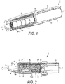
Figure 1 is a perspective, partially cut-away illustration of an apparatus configured to heat smokable material to release aromatic compounds and/or nicotine from the smokable material; -
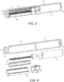
figure 2 is an illustration of an apparatus configured to heat smokable material, in which a heater is located externally of a smokable material heating chamber so as to provide heat in a radially inward direction to heat smokable material therein; -
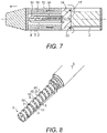
figure 3 is a perspective, partially cut-away illustration of an apparatus configured to heat smokable material, in which the smokable material is provided around an elongate ceramic heater divided into radial heating sections; -
figure 4 is an exploded, partially cut-away view of an apparatus configured to heat smokable material, in which the smokable material is provided around an elongate ceramic heater divided into radial heating sections; -
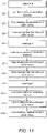
figure 5 is a perspective, partially cut-away illustration of an apparatus configured to heat smokable material, in which the smokable material is provided around an elongate infra-red heater; -
figure 6 is an exploded, partially cut-away illustration of an apparatus configured to heat smokable material, in which the smokable material is provided around an elongate infra-red heater; -
figure 7 is a schematic illustration of part of an apparatus configured to heat smokable material, in which the smokable material is provided around a plurality of longitudinal, elongate heating sections spaced around a central longitudinal axis; -
figure 8 is a perspective illustration of part of an apparatus configured to heat smokable material, in which the regions of smokable material are provided between pairs of upstanding heating plates; -
figure 9 is a perspective illustration of the apparatus shown infigure 7 , in which an external housing is additionally illustrated; -
figure 10 is an exploded view of part of an apparatus configured to heat smokable material, in which the regions of smokable material are provided between pairs of upstanding heating plates; -
figure 11 is a flow diagram showing a method of activating heating regions and opening and closing heating chamber valves during puffing; -
figure 12 is a schematic illustration of a gaseous flow through an apparatus configured to heat smokable material; -
figure 13 is a graphical illustration of a heating pattern which can be used to heat smokable material using a heater; -
figure 14 is a schematic, cross-sectional illustration of a section of vacuum insulation configured to insulate heated smokable material from heat loss; -
figure 15 is another schematic, cross-sectional illustration of a section of vacuum insulation configured to insulate heated smokable material from heat loss; -
figure 16 is a schematic, cross-sectional illustration of a heat resistive thermal bridge which follows an indirect path from a higher temperature insulation wall to a lower temperature insulation wall; -
figure 17 is a schematic, cross-sectional illustration of a heat shield and a heat-transparent window which are moveable relative to a body of smokable material to selectively allow thermal energy to be transmitted to different sections of the smokable material through the window; and -
figure 18 is schematic, cross sectional illustration of part of an apparatus configured to heat smokable material, in which a heating chamber is hermetically sealable by check valves. - As used herein, the term 'smokable material' includes any material that provides volatilized components upon heating and includes any tobacco-containing material and may, for example, include one or more of tobacco, tobacco derivatives, expanded tobacco, reconstituted tobacco or tobacco substitutes.
- An
apparatus 1 for heating smokable material comprises anenergy source 2, aheater 3 and aheating chamber 4. Theenergy source 2 may comprise a battery such as a Li-ion battery, Ni battery, Alkaline battery and/or the like, and is electrically coupled to theheater 3 to supply electrical energy to theheater 3 when required. Theheating chamber 4 is configured to receivesmokable material 5 so that thesmokable material 5 can be heated in theheating chamber 4. Theheating chamber 4 is located adjacent to theheater 3 so that thermal energy from theheater 3 heats thesmokable material 5 therein to volatilize aromatic compounds and nicotine in thesmokable material 5, without burning thesmokable material 5. Amouthpiece 6 is provided through which a user of theapparatus 1 can inhale the volatilized compounds during use of theapparatus 1. Thesmokable material 5 may comprise a tobacco blend. - The
heater 3 may comprise a substantially cylindrical,elongate heater 3 and theheating chamber 4 may be located either outwardly or inwardly of a longitudinal external surface of theheater 3. For example, with reference tofigure 1 , theheating chamber 4 may be located around the outside of a circumferential, longitudinal surface of theheater 3. Theheating chamber 4 andsmokable material 5 may therefore comprise co-axial layers around theheater 3. Alternatively, referring tofigure 2 , theheating chamber 4 may be located internally of the longitudinal surface of theheater 3 so that theheating chamber 4 comprises a core or other cavity internal of the heating surface. As will be evident from the discussion below, other shapes and configurations of theheater 3 andheating chamber 4 can alternatively be used. - A
housing 7 may contain components of theapparatus 1 such as theenergy source 2 andheater 3. Thehousing 7 may comprise an approximately cylindrical tube with theenergy source 2 located towards itsfirst end 8 and theheater 3 andheating chamber 4 located towards its opposite,second end 9. Theenergy source 2 andheater 3 extend along the longitudinal axis of thehousing 7. For example, as shown infigures 1 and 2 , theenergy source 2 andheater 3 can be aligned along the central longitudinal axis of thehousing 7 in a substantially end-to-end arrangement so that an end face of theenergy source 2 substantially faces an end face of theheater 3. Heat insulation may be provided between theenergy source 2 and theheater 3 to prevent direct transfer of heat from one to the other. - The length of the
housing 7 may be approximately 130mm, the length of the energy source may be approximately 59mm, and the length of theheater 3 andheating region 4 may be approximately 50mm. The diameter of thehousing 7 may be between approximately 9mm and approximately 18mm. For example, the diameter of the housing'sfirst end 8 may be between 15mm and 18mm whilst the diameter of themouthpiece 6 at the housing'ssecond end 9 may between 9mm and 15mm. The diameter of theheater 3 may be between approximately 2.0mm and approximately 13-0mm, depending on the heater configuration. For example, aheater 3 located externally of theheating chamber 4 such as that shown infigure 2 may have a diameter of between approximately 9.0mm and approximately 13.0mm whilst the diameter of aheater 3 located internally of theheating chamber 4, such as that shown infigure 1 , may be between approximately 2.0mm and approximately 4.5mm, such as between approximately 4.0mm and approximately 4.5mm or between approximately 2.0mm and approximately 3.0mm. Heater diameters outside these ranges may alternatively be used. The diameter of theheating chamber 4 may be between approximately 5.0mm and approximately 10.0mm. For example, aheating chamber 4 located outwardly of theheater 3, such as that shown infigure 1 , may have an exterior diameter of approximately 10mm at its outwardly-facing surface whilst aheating chamber 4 located inwardly of theheater 3, such as that shown infigure 2 , may have a diameter of between approximately 5mm and approximately 8.0mm such as between approximately 3.0mm and approximately 6.0mm. The diameter of theenergy source 2 may be between approximately 14.0mm and approximately 15.0mm, such as 14.6mm although other diameters ofenergy source 2 could equally be used. - The
mouthpiece 6 can be located at thesecond end 9 of thehousing 7, adjacent theheating chamber 4 andsmokable material 5. Thehousing 7 is suitable for being gripped by a user during use of theapparatus 1 so that the user can inhale volatilized smokable material compounds from themouthpiece 6 of theapparatus 1. - The
heater 3 may comprise aceramics heater 3, examples of which are shown infigures 1 to 4 . Theceramics heater 3 may, for example, comprise base ceramics of alumina and/or silicon nitride which are laminated and sintered. - Alternatively, referring to
figures 5 and 6 , theheater 3 may comprise an infra-red (IR)heater 3 such as a halogen-IR lamp 3. TheIR heater 3 may have a low mass and therefore its use can help to reduce the overall mass of theapparatus 1. For example, the mass of the IR heater may be 20% to 30% less than the mass of aceramics heater 3 having an equivalent heating power output. TheIR heater 3 also has low thermal inertia and therefore is able to heat thesmokable material 5 very rapidly in response to an activation stimulus. TheIR heater 3 may be configured to emit IR electromagnetic radiation of between approximately 700nm and 4.5 µm in wavelength. Another alternative is to use aresistive heater 3, such as a resistive wire wound on a ceramic insulation layer deposited on a wall of thethermal insulation 18 referred to further below. - As indicated above and shown in
figure 1 , theheater 3 may be located in a central region of thehousing 7 and theheating chamber 4 andsmokable material 5 may be located around the longitudinal surface of theheater 3. In this arrangement, thermal energy emitted by theheater 3 may travel in a radial direction outwards from the longitudinal surface of theheater 3 into theheating chamber 4 and thesmokable material 5. Alternatively, as shown infigure 2 , theheater 3 may be located towards the periphery of thehousing 7 and theheating chamber 4 andsmokable material 5 may be located in a central region of thehousing 7 which is internal from the longitudinal surface of theheater 3. In this arrangement, thermal energy emitted by theheater 3 travels in a radial direction inwards from a longitudinal surface of theheater 3 into theheating chamber 4 and thesmokable material 5. - The
heater 3 comprises a plurality ofindividual heating regions 10, as shown infigures 2 and3 . Theheating regions 10 are operable independently of one another so thatdifferent regions 10 can be activated at different times to heat thesmokable material 5. Theheating regions 10 may be arranged in theheater 3 in any geometric arrangement. However, in the examples shown in the figures, theheating regions 10 are geometrically arranged in theheater 3 so that different ones of theheating regions 10 are arranged to predominately and independently heat different regions of thesmokable material 5. - For example, referring to
figures 2 and3 , theheater 3 may comprise a plurality of axially alignedheating regions 10 in a substantially elongate arrangement. - The
regions 10 may each comprise an individual element of theheater 3. Theheating regions 10 may, for example, all be aligned with each other along a longitudinal axis of theheater 3, thus providing a plurality of independent heating zones along the length of theheater 3. Eachheating region 10 may comprise aheating cylinder 10 having a finite length which is significantly less than the length of theheater 3 as a whole. Thecylinders 10 may comprise solid disks where each disk has a depth equivalent to the cylinder length referred to above. An example of this is shown infigure 3 . Alternatively, thecylinders 10 may comprise hollow rings, an example of which is shown infigure 2 . In this case, the arrangement of axially alignedheating regions 10 define the exterior of theheating chamber 4 and are configured to apply heat inwardly, predominately towards the central longitudinal axis of thechamber 4. Theheating regions 10 are arranged with their radial, or otherwise transverse, surfaces facing one another along the length of theheater 3. The transverse surfaces of eachregion 10 may touch the transverse surfaces of its neighbouringregions 10. Alternatively, the transverse surfaces of eachregion 10 may be separated from the transverse surfaces of its neighbouring region(s) 10.Thermal insulation 18 may be present between such separatedheating regions 10, as discussed in more detail below. An example of this is shown infigure 2 . - In this way, when a particular one of the
heating regions 10 is activated, it supplies thermal energy to thesmokable material 5 located radially inwardly or outwardly of theheating region 10 without substantially heating the remainder of thesmokable material 5. For example, referring tofigure 3 , the heated region ofsmokable material 5 may comprise a ring ofsmokable material 5 located around theheating region 10 which has been activated. Thesmokable material 5 can therefore be heated in independent sections, for example ring or core sections, where each section corresponds tosmokable material 5 located directly inwardly or outwardly of a particular one of theheating regions 10 and has a mass and volume which is significantly less than the body ofsmokable material 5 as a whole. - In another alternative configuration, referring to
figure 7 , theheater 3 may comprise a plurality of elongate, longitudinally extendingheating regions 10 positioned at different locations around the central longitudinal axis of theheater 3. Although shown as being of different lengths infigure 7 , the longitudinally extendingheating regions 10 may be of substantially the same length so that each extends along substantially the whole length of theheater 3. Eachheating region 10 may comprise, for example, an individualIR heating element 10 such as anIR heating filament 10. Optionally, a body of heat insulation or heat reflective material may be provided along the central longitudinal axis of theheater 3 so that thermal energy emitted by eachheating region 10 travels predominately outwards from theheater 3 into theheating chamber 4 and thus heats thesmokable material 5. The distance between the central longitudinal axis of theheater 3 and each of theheating regions 10 may be substantially equal. Theheating regions 10 may optionally be contained in a substantially infra-red and/or heat transparent tube, or other housing, which forms a longitudinal surface of theheater 3. Theheating regions 10 may be fixed in position relative to theother heating regions 10 inside the tube. - In this way, when a particular one of the
heating regions 10 is activated, it supplies thermal energy to thesmokable material 5 located adjacent to theheating region 10 without substantially heating the remainder of thesmokable material 5. The heated section ofsmokable material 5 may comprise a longitudinal section ofsmokable material 5 which lies parallel and directly adjacent to thelongitudinal heating region 10. Therefore, as with the previous examples, thesmokable material 5 can be heated in independent sections. - As will be described further below, the
heating regions 10 can each be individually and selectively activated. - The
smokable material 5 may be comprised in acartridge 11 which can be inserted into theheating chamber 4. For example, as shown infigure 1 , thecartridge 11 can comprise asmokable material tube 11 which can be inserted around theheater 3 so that the internal surface of thesmokable material tube 11 faces the longitudinal surface of theheater 3. Thesmokable material tube 11 may be hollow. The diameter of the hollow centre of thetube 11 may be substantially equal to, or slightly larger than, the diameter of theheater 3 so that thetube 11 is a close fit around theheater 3. Alternatively, referring tofigure 2 , thecartridge 11 may comprise a substantially solid rod ofsmokable material 5 which can be inserted into aheating chamber 4 located inwardly of theheater 3 so that the external longitudinal surface of therod 11 faces the internal longitudinal surface of theheater 3. The length of thecartridge 11 may be approximately equal to the length of theheater 3 so that theheater 3 can heat thecartridge 11 along its whole length. - In another alternative configuration of
heater 3, theheater 3 comprises a spirally shapedheater 3. The spirally shapedheater 3 may be configured to screw into thesmokable material cartridge 11 and may comprise adjacent, axially-alignedheating regions 10 so as to operate in substantially the same manner as described for the linear,elongate heater 3 discussed above with reference tofigures 1 and3 . - Alternatively, referring to
figures 8 ,9 and 10 , a different geometrical configuration ofheater 3 andsmokable material 5 can be used. More particularly, theheater 3 can comprise a plurality ofheating regions 10 which extend directly into anelongate heating chamber 4 which is divided into sections by theheating regions 10. During use, theheating regions 10 extend directly into an elongatesmokable material cartridge 11 or other substantially solid body ofsmokable material 5. Thesmokable material 5 in theheating chamber 4 is thereby divided into discrete sections separated from each other by the spaced-apartheating regions 10. Theheater 3,heating chamber 4 andsmokable material 5 may extend together along a central, longitudinal axis of thehousing 7. As shown infigures 8 and10 , theheating regions 10 may each comprise aprojection 10, such as anupstanding heating plate 10, which extends into the body ofsmokable material 5. Theprojections 10 are discussed below in the context ofheating plates 10. The principal plane of theheating plates 10 may be substantially perpendicular to the principal longitudinal axis of the body ofsmokable material 5 andheating chamber 4 and/orhousing 7. Theheating plates 10 may be parallel to one another, as shown infigures 8 and10 . Each section ofsmokable material 5 is bounded by a main heating surface of a pair ofheating plates 10 located either side of the smokable material section, so that activation of one or both of theheating plates 10 will cause thermal energy to be transferred directly into thesmokable material 5. The heating surfaces may be embossed to increase the surface area of theheating plate 10 against thesmokable material 5. Optionally, eachheating plate 10 may comprise a thermally reflective layer which divides theplate 10 into two halves along its principal plane. Each half of theplate 10 can thus constitute aseparate heating region 10 and may be independently activated to heat only the section ofsmokable material 5 which lies directly against that half of theplate 10, rather than thesmokable material 5 on both sides of theplate 10.Adjacent plates 10, or facing portions thereof, may be activated to heat a section ofsmokable material 5, which is located between the adjacent plates, from substantially opposite sides of the section ofsmokable material 5. - The elongate smokable material cartridge or
body 11 can be installed between, and removed from, theheating chamber 4 andheating plates 10 by removing a section of thehousing 7 at the housing'ssecond end 9, as previously described. Theheating regions 10 can be individually and selectively activated to heat different sections of thesmokable material 5 as required. - In this way, when a particular one or pair of the
heating regions 10 is activated, it supplies thermal energy to thesmokable material 5 located directly adjacent to the heating region(s) 10 without substantially heating the remainder of thesmokable material 5. The heated section ofsmokable material 5 may comprise a radial section ofsmokable material 5 located between theheating regions 10, as shown infigures 8 to 10 . - The
housing 7 of theapparatus 1 may comprise an opening through which thecartridge 11 can be inserted into theheating chamber 4. The opening may, for example, comprise an opening located at the housing'ssecond end 9 so that thecartridge 11 can be slid into the opening and pushed directly into theheating chamber 4. The opening is preferably closed during use of theapparatus 1 to heat thesmokable material 5. Alternatively, a section of thehousing 7 at thesecond end 9 is removable from theapparatus 1 so that thesmokable material 5 can be inserted into theheating chamber 4. An example of this is shown infigure 10 . Theapparatus 1 may optionally be equipped with a user-operable smokable material ejection unit, such as an internal mechanism configured to slide usedsmokable material 5 off and/or away from theheater 3. The usedsmokable material 5 may, for example, be pushed back through the opening in thehousing 7. Anew cartridge 11 can then be inserted as required. -
Thermal insulation 18 may be provided between thesmokable material 5 and anexternal surface 19 of thehousing 7. The thermal insulation reduces heat loss from theapparatus 1 and therefore improves the efficiency with which thesmokable material 5 is heated. Referring tofigure 14 , theinsulation 18 may comprisevacuum insulation 18. For example, theinsulation 18 may comprise a layer which is bounded by awall material 19 such as a metallic material. An internal region orcore 20 of theinsulation 18 may comprise an open-cell porous material, for example comprising polymers, aerogels or other suitable material, which is evacuated to a low pressure. Theinternal region 20 of theinsulation 18 is configured to absorb gases which may be generated inside theregion 20 to thereby maintain a vacuum state. The pressure in theinternal region 20 may be in the range of o.1 to 0.001 mbar. Thewall 19 of theinsulation 18 is sufficiently strong to withstand the force exerted against it due to the pressure differential between the core 20 and external surfaces of thewall 19, thereby preventing theinsulation 18 from collapsing. Thewall 19 may, for example, comprise astainless steel wall 19 having a thickness of approximately 100µm. The thermal conductivity of theinsulation 18 may be in the range of 0.004 to 0.005 W/mK. The heat transfer coefficient of theinsulation 18 may be between approximately 1.10 W/(m2K) and approximately 1.40 W/(m2K) within a temperature range of between approximately 100 degrees Celsius and 250 degrees Celsius, such as within a range of between approximately 150 degrees Celsius and approximately 250 degrees Celsius. The gaseous conductivity of theinsulation 18 is negligible. A reflective coating may be applied to the internal surfaces of thewall material 19 to minimize heat losses due to radiation propagating through theinsulation 18. The coating may, for example, comprise an aluminium IR reflective coating having a thickness of between approximately 0.3µm and 1.0µm. The evacuated state of theinternal core region 20 means that theinsulation 18 functions even when the thickness of thecore region 20 is very small. The insulating properties are substantially unaffected by its thickness. This helps to reduce the overall size, particularly the diameter, of theapparatus 1. - As shown in
figure 14 , thewall 19 comprises an inwardly-facingsection 21 and an outwardly-facingsection 22. The inwardly-facingsection 21 substantially faces thesmokable material 5 andheating chamber 4. The outwardly-facingsection 22 substantially faces the exterior of thehousing 7. During operation of theapparatus 1, the inwardly-facingsection 21 may be warmer due to the thermal energy originating from theheater 3, whilst the outwardly-facingsection 22 is cooler due to the effect of theinsulation 18. The inwardly-facingsection 21 and the outwardly-facingsection 22 may both comprise substantially longitudinally-extendingwalls 19 which are at least as long as theheater 3 andheating chamber 4. The internal surface of the outwardly-facingwall section 22, i.e. the surface facing the evacuatedcore region 20, may comprise a coating for absorbing gas in thecore 20. A suitable coating is a titanium oxide film. - As illustrated in
figure 2 , the overall length of the body ofinsulation 18 may be greater than the length of theheating chamber 4 andheater 3 so as to further reduce heat loss from theapparatus 1 to the atmosphere outside thehousing 7. For example, thethermal insulation 18 may be between approximately 70mm and approximately 80mm. - Referring to the schematic illustrations in
figures 14 and 15 , athermal bridge 23 may connect the inwardly-facingwall section 21 to the outwardly-facingwall section 22 at the ends of theinsulation 18 in order to completely encompass and contain thelow pressure core 20. Thethermal bridge 23 may comprise awall 19 formed of the same material as the inwardly and outwardly-facingsections thermal bridge 23 has a greater thermal conductivity than the insulatingcore 20 and so has a greater potential to undesirably conduct heat out of theapparatus 1 and thereby reduce the efficiency with which thesmokable material 5 is heated than thecore 20. - To reduce heat losses due to the
thermal bridge 23, thethermal bridge 23 may be extended to increase its resistance to heat flow from the inwardly-facingsection 21 to the outwardly-facingsection 22. This is schematically illustrated infigure 16 . For example, thethermal bridge 23 may follow an indirect path between the inwardly-facingsection 21 of thewall 19 and the outwardly-facingsection 22 of thewall 19. Thethermal bridge 23 is present at a longitudinal location in theapparatus 1 where theheater 3 andheating chamber 4 are not present. This means that thethermal bridge 23 gradually extends from the inwardly-facingsection 21 to the outwardly-facingsection 22 along the indirect path, thereby reducing the thickness of the core 20 to zero, at a longitudinal location in thehousing 7 where theheater 3,heating chamber 4 andsmokable material 5 are not present, thereby further limiting the conduction of heat out of theapparatus 1. - As referred to above with reference to
figure 2 , theheater 3 may be integrated with thethermal insulation 18. For example, thethermal insulation 18 may comprise a substantially elongate, hollow body, such as a substantially cylindrical tube ofinsulation 18 which is located co-axially around theheating chamber 4 and into which theheating regions 10 are integrated. Thethermal insulation 18 may comprise a layer in which recesses are provided in the inwardly facingsurface profile 21.Heating regions 10 are located in these recesses so that theheating regions 10 face thesmokable material 5 in theheating chamber 4. The surfaces of theheating regions 10 which face theheating chamber 4 may be flush with theinside surface 21 of thethermal insulation 18 in regions of theinsulation 18 which are not recessed. - Integrating the
heater 3 with thethermal insulation 18 means that theheating regions 10 are substantially surrounded by theinsulation 18 on all sides of theheating regions 10 other than those which face inwardly towards the smokablematerial heating chamber 4. As such, heat emitted by theheater 3 is concentrated in thesmokable material 5 and does not dissipate into other parts of theapparatus 1 or into the atmosphere outside thehousing 7. - The integration of the
heater 3 with thethermal insulation 18 also reduces the thickness of the combination ofheater 3 andthermal insulation 18 compared to providing theheater 3 separately and internally of a layer ofthermal insulation 18. This can allow the diameter of theapparatus 1, in particular the external diameter of thehousing 7, to be reduced resulting in a conveniently sized slim-line product. - Alternatively, the reduction in thickness provided by the integration of the
heater 3 with thethermal insulation 18 can allow a wider smokablematerial heating chamber 4 to be accommodated in theapparatus 1, or the introduction of further components, without any increase in the overall width of thehousing 7, as compared to a device in which theheater 3 is separate and positioned internally from a layer ofthermal insulation 18. - A benefit of integrating the
heater 3 with theinsulation 18 is that the size and weight of the combination ofheater 3 andinsulation 18 can be reduced compared to devices in which there is no integration of heater and insulation. Reduction of the heater size allows for a corresponding reduction in the diameter of the housing. Reduction of the heater weight, in turn, decreases the heating ramp-up time and thereby reduces the warming-up time of theapparatus 1. - Additionally or alternatively to the
thermal insulation 18, a heat reflecting layer may be present between the transverse surfaces of theheating regions 10. The arrangement of theheating regions 10 relative to each other may be such that thermal energy emitted from each one of theheating regions 10 does not substantially heat the neighbouringheating regions 10 and instead travels predominately into theheating chamber 4 andsmokable material 5. Eachheating region 10 may have substantially the same dimensions as theother regions 10. - The
apparatus 1 may comprise acontroller 12, such as amicrocontroller 12, which is configured to control operation of theapparatus 1. Thecontroller 12 is electronically connected to the other components of theapparatus 1 such as theenergy source 2 andheater 3 so that it can control their operation by sending and receiving signals. Thecontroller 12 is, in particular, configured to control activation of theheater 3 to heat thesmokable material 5. For example, thecontroller 12 may be configured to activate theheater 3, which may comprise selectively activating one ormore heating regions 10, in response to a user drawing on themouthpiece 6 of theapparatus 1. In this regard, thecontroller 12 may be in communication with apuff sensor 13 via a suitable communicative coupling. Thepuff sensor 13 is configured to detect when a puff occurs at themouthpiece 6 and, in response, is configured to send a signal to thecontroller 12 indicative of the puff. An electronic signal may be used. Thecontroller 12 may respond to the signal from thepuff sensor 13 by activating theheater 3 and thereby heating thesmokable material 5. The use of apuff sensor 13 to activate theheater 3 is not, however, essential and other means for providing a stimulus to activate theheater 3, such as a user-operable actuator, can alternatively be used. The volatilized compounds released during heating can then be inhaled by the user through themouthpiece 6. Thecontroller 12 can be located at any suitable position within thehousing 7. An example position is between theenergy source 2 and theheater 3/heating chamber 4, as illustrated infigure 4 . - The
controller 12 may be configured to activate, or otherwise cause warming of, theindividual heating regions 10 in a predetermined order or pattern. For example, thecontroller 12 may be configured to activate theheating regions 10 sequentially along or around theheating chamber 4. Each activation of aheating region 10 may be in response to detection of a puff by thepuff sensor 13 or may be triggered in an alternative way such as by the elapse of a predetermined period of time after the activation of theprevious heating region 10 or by elapse of a predetermined period of time after initial activation of the heater (e.g. activation of the first region 10), as described further below. - Referring to
figure 11 , an example heating method may comprise a first step S1 in which an activation stimulus such as a first puff is detected followed by a second step S2 in which a first section ofsmokable material 5 is heated in response to the activation stimulus. In a third step S3, hermetically sealable inlet andoutlet valves 24 may be opened to allow air to be drawn through theheating chamber 4 and out of theapparatus 1 through themouthpiece 6. In a fourth step, thevalves 24 are closed. Thesevalves 24 are described in more detail below with respect tofigures 2 and18 . In fifth S5, sixth S6, seventh S7 and eighth S8 steps, a second section ofsmokable material 5 may be heated, for example in response to another activation stimulus such as a second puff, with a corresponding opening and closing of the heating chamber inlet andoutlet valves 24. In ninth S9, tenth S10, eleventh S11 and twelfth S12 steps, a third section of thesmokable material 5 may be heated, for example in response to another activation stimulus such as a third puff, with a corresponding opening and closing of the heating chamber inlet andoutlet valves 24, and so on. Means other than apuff sensor 13 could alternatively be used. For example, a user of theapparatus 1 may actuate a control switch to indicate that he/she is taking a new puff. - In this way, a fresh section of
smokable material 5 may be heated to volatilize nicotine and aromatic compounds for each new puff or in response to a given quantity of certain components, such as nicotine and/or aromatic compounds, being released from the previously heated section ofsmokable material 5. The number ofheating regions 10 and/or independently heatable sections ofsmokable material 5 may correspond to the number of puffs for which thecartridge 11 is intended to be used. Alternatively, each independently heatablesmokable material section 5 may be heated by its corresponding heating region(s) 10 for a plurality of puffs such as two, three or four puffs, so that a fresh section ofsmokable material 5 is heated only after a plurality of puffs have been taken whilst heating the previous smokable material section. - As briefly referred to above, instead of activating each
heating region 10 in response to an individual puff, theheating regions 10 may alternatively be activated sequentially, for example over a predetermined period of use, one after the other. This may occur in response to an initial activation stimulus such as a single, initial puff at themouthpiece 6. For example, theheating regions 10 may be activated at regular, predetermined intervals over the expected inhalation period for a particularsmokable material cartridge 11. The predetermined intervals may correspond to the period which is taken to release a given amount of certain components such as nicotine and/or aromatic compounds from each smokable material section. An example interval is between approximately 60 and 240 seconds. Therefore, at least the fifth and ninth steps S5, S9 shown infigure 11 are optional. Eachheating region 10 may continue to be activated for a predetermined period, which may correspond to the duration of the intervals referred to above or may be longer, as described below. Once all of theheating regions 10 have been activated for aparticular cartridge 11, thecontroller 12 may be configured to indicate to the user that thecartridge 11 should be changed. Thecontroller 12 may, for example, activate an indicator light at the external surface of thehousing 7. - It will be appreciated that activating
individual heating regions 10 in order rather than activating theentire heater 3 means that the energy required to heat thesmokable material 5 is reduced over what would be required if theheater 3 were activated fully over the entire inhalation period of acartridge 11. Therefore, the maximum required power output of theenergy source 2 is also reduced. This means that a smaller andlighter energy source 2 can be installed in theapparatus 1. - The
controller 12 may be configured to de-activate theheater 3, or reduce the power being supplied to theheater 3, in between puffs. This saves energy and extends the life of theenergy source 2. For example, upon theapparatus 1 being switched on by a user or in response to some other stimulus, such as detection of a user placing their mouth against themouthpiece 6, thecontroller 12 may be configured to cause theheater 3, ornext heating region 10 to be used to heat thesmokable material 5, to be partially activated so that it heats up in preparation to volatilize components of thesmokable material 5. The partial activation does not heat thesmokable material 5 to a sufficient temperature to volatilize nicotine. A suitable temperature may be 100 °C or below, although temperatures below 120 °C could be used. An example is a temperature between 60 °C and 100 °C, such as a temperature between 80 °C and 100 °C. The temperature may be less than 100 °C. In response to detection of a puff by thepuff sensor 13, or some other stimulus such as the elapse of a predetermined time period, thecontroller 12 may then cause theheater 3 orheating region 10 in question to heat thesmokable material 5 further in order to rapidly volatilize the nicotine and other aromatic compounds for inhalation by the user. The temperature of a partiallyheated heating region 10 can be increased to full volatizing temperature in a shorter time period than if theheating region 10 was started from 'cold', i.e. without being partially heated. - If the
smokable material 5 comprises tobacco, a suitable temperature for volatilizing the nicotine and other aromatic compounds may be 100°C or above, such as 120°C or above. An example is a temperature between 100 °C and 250 °C, such as between 100 °C and 220 °C, between 100 °C and 200 °C, between 150 °C and 250 °C or between 130 °C and 180 °C. The temperature may be more than 100 °C. An example full activation temperature is 150 °C, although other values such as 250°C are also possible. A super-capacitor can optionally be used to provide the peak current used to heat thesmokable material 5 to the volatization temperature. An example of a suitable heating pattern is shown infigure 13 , in which the peaks may respectively represent the full activation ofdifferent heating regions 10. As can be seen, thesmokable material 5 is maintained at the volatization temperature for the approximate period of the puff which, in this example, is two seconds. - Three example operational modes of the
heater 3 are described below. - In a first operational mode, during full activation of a
particular heating region 10, allother heating regions 10 of the heater are deactivated. Therefore, when anew heating region 10 is activated, the previous heating region is deactivated. Power is supplied only to the activatedregion 10. Theheating regions 10 may be activated sequentially along the length of theheater 3 so that nicotine and aromatic compounds are regularly released from fresh portions ofsmokable material 5 until thecartridge 11 is exhausted. This mode provides more uniform nicotine and smokable material flavour delivery than full activation of allheating regions 10 for the duration of the heating period of thecartridge 11. As with the other modes described below, power is also saved by not fully activating all of theheating regions 10 for the duration of the heating period of thesmokable material cartridge 11. - Alternatively, in a second operational mode, once a
particular heating region 10 has been activated, it remains fully activated until theheater 3 is switched off. Therefore, the power supplied to theheater 3 incrementally increases as more of theheating regions 10 are activated during inhalation from thecartridge 11. The continuing activation of theheating regions 10 throughout thechamber 4 substantially prevents condensation of components such as nicotine volatized from thesmokable material 5 in theheating chamber 4. - Alternatively, in a third operational mode, during full activation of a
particular heating region 10, one or more of theother heating regions 10 may be partially activated. Partial activation of the one or moreother heating regions 10 may comprise heating the other heating region(s) 10 to a temperature which is sufficient to substantially prevent condensation of components such as nicotine volatized from thesmokable material 5 in theheating chamber 4. An example is 100 °C. Other examples include the ranges of partial activation temperatures previously described. The temperature of theheating regions 10 which are partially activated is less than the temperature of theheating region 10 which is fully activated. Thesmokable material 10 located adjacent the partially activatedregions 10 is not heated to a temperature sufficient to volatize components of thesmokable material 5. For example, upon full activation of anew heating region 10, the previously fully activatedheating region 10 is partially but not fully deactivated so as to continue to heat its adjacentsmokable material 5 at a lower temperature and thus prevent condensation of volatized components in theheating chamber 4. Retaining the previous, or any other,heating regions 10 in a partially rather than fully activated state during full activation of one or moreother heating regions 10 prevents thesmokable material 5 adjacent the fully activatedregions 10 from becoming overly toasted and thus avoids potential negative effects on the flavours experienced by the user of theapparatus 1. - For any of the alternatives described above, the
heating regions 10 may either be heated to full operational temperature immediately after activation or may initially be heated to a lower temperature, as previously discussed, before being fully activated after a predetermined period of time to heat thesmokable material 5 to volatize nicotine and other aromatic compounds. - The
apparatus 1 may comprise a heat shield 3a, which is located between theheater 3 and theheating chamber 4/smokable material 5. The heat shield 3a is configured to substantially prevent thermal energy from flowing through the heat shield 3a and therefore can be used to selectively prevent thesmokable material 5 from being heated even when theheater 3 is activated and emitting thermal energy. Referring tofigure 17 , the heat shield 3a may, for example, comprise a cylindrical layer of heat reflective material which is located co-axially around theheater 3. Alternatively, if theheater 3 is located around theheating chamber 4 andsmokable material 5 as previously described with reference tofigure 2 , the heat shield 3a may comprise a cylindrical layer of heat reflective material which is located co-axially around theheating chamber 4 and co-axially inside of theheater 3. The heat shield 3a may additionally or alternatively comprise a heat-insulating layer configured to insulate theheater 3 from thesmokable material 5. - The heat shield 3a comprises a substantially heat-
transparent window 3b which allows thermal energy to propagate through thewindow 3b and into theheating chamber 4 andsmokable material 5. Therefore, the section ofsmokable material 5 which is aligned with thewindow 3b is heated whilst the remainder of thesmokable material 5 is not. The heat shield 3a andwindow 3b may be rotatable or otherwise moveable with respect thesmokable material 5 so that different sections of thesmokable material 5 can be selectively and individually heated by rotating or moving the heat shield 3a andwindow 3b. The effect may be similar to the effect provided by selectively and individually activating theheating regions 10 referred to previously. For example, the heat shield 3a andwindow 3b may be rotated or otherwise moved incrementally in response to a signal from thepuff detector 13. Additionally or alternatively, the heat shield 3a andwindow 3b may be rotated or otherwise moved incrementally in response to a predetermined heating period having elapsed. Movement or rotation of the heat shield 3a andwindow 3b may be controlled by electronic signals from thecontroller 12. The relative rotation or other movement of the heat shield 3a/window 3b andsmokable material 5 may be driven by a stepper motor 3c under the control of thecontroller 12. This is illustrated infigure 17 . Alternatively, the heat shield 3a andwindow 3b may be manually rotated using a user control such as an actuator on thehousing 7. The heat shield 3a does not need to be cylindrical and may optionally comprise one or more suitably positioned longitudinally extending elements and or/plates. - It will be appreciated that a similar result can be obtained by rotating or moving the
smokable material 5 relative to theheater 3, heat shield 3a andwindow 3b. For example, theheating chamber 4 may be rotatable around theheater 3. If this is the case, the above description relating to movement of the heat shield 3a can be applied instead to movement of theheating chamber 4 relative to the heat shield 3a. - The heat shield 3a may comprise a coating on the longitudinal surface of the
heater 3. In this case, an area of the heater's surface is left uncoated to form the heat-transparent window 3b. Theheater 3 can be rotated or otherwise moved, for example under the control of thecontroller 12 or user controls, to cause different sections of thesmokable material 5 to be heated. Alternatively, the heat shield 3a andwindow 3b may comprise a separate shield 3a which is rotatable or otherwise moveable relative to both theheater 3 and thesmokable material 5 under the control of thecontroller 12 or other user controls. - Referring to
figure 7 , theapparatus 1 may compriseair inlets 14 which allow external air to be drawn into thehousing 7 and through the heatedsmokable material 5 during puffing. The air inlets 14 may compriseapertures 14 in thehousing 7 and may be located upstream from thesmokable material 5 andheating chamber 4 towards thefirst end 8 of thehousing 7. This is shown infigures 2 ,12 and18 . Air drawn in through theinlets 14 travels through the heatedsmokable material 5 and therein is enriched with smokable material vapours, such as aroma vapours, before passing through theoutlet valves 24 and being inhaled by the user at themouthpiece 6. Optionally, as shown infigure 12 , theapparatus 1 may comprise aheat exchanger 15 configured to warm the air before it enters thesmokable material 5 and/or to cool the air before it is drawn through themouthpiece 6. For example, theheat exchanger 15 may be configured to use heat extracted from the air entering themouthpiece 6 to warm new air before it enters thesmokable material 5. - Referring to
figure 18 , as previously discussed, theheating chamber 4 insulated by theinsulation 18 may comprise inlet andoutlet valves 24, such as check valves, which hermetically seal theheating chamber 4 when closed. Thevalves 24 may be one-way valves, where the inlet valve(s) 24 allows gaseous flow into thechamber 4 and the outlet valve(s) 24 allows gaseous flow out of thechamber 4. Gaseous flow in the opposite direction is prevented. Thevalves 24 can thereby prevent air from undesirably entering and exiting thechamber 4 and can prevent smokable material flavours from exiting thechamber 4. The inlet andoutlet valves 24 may, for example, be provided in theinsulation 18. Between puffs, thevalves 24 may be closed by thecontroller 12, or other means such as a manually-operable actuator, so that all volatilized substances remain contained inside thechamber 4 in-between puffs. The partial pressure of the volatized substances between puffs reaches the saturated vapour pressure and the amount of evaporated substances therefore depends only on the temperature in theheating chamber 4. This helps to ensure that the delivery of volatilized nicotine and aromatic compounds remains constant from puff to puff. - During puffing, the
valves 24 open so that air can flow through thechamber 4 to carry volatilized smokable material components to themouthpiece 6. Opening of thevalves 24 may be caused by thecontroller 12 or by other means. A membrane can be located in thevalves 24 to ensure that no oxygen enters thechamber 4. Thevalves 24 may be breath-actuated so that thevalves 24 open in response to detection of a puff at themouthpiece 6. Thevalves 24 may close in response to a detection that a puff has ended. Alternatively, thevalves 24 may close following the elapse of a predetermined period after their opening. The predetermined period may be timed by thecontroller 12. Optionally, a mechanical or other suitable opening/closing means may be present so that thevalves 24 open and close automatically. For example, the gaseous movement caused by a user puffing on themouthpiece 6 may exert a force on thevalves 24 to cause them to open and close. Therefore, the use of thecontroller 12 is not required to actuate thevalves 24.
The mass of thesmokable material 5 which is heated by theheater 3, for example by eachheating region 10, may be in the range of 0.2 to 1.0g. The temperature to which thesmokable material 5 is heated may be user controllable, for example to any temperature within the temperature range of 1000 °C to 250 °C, such as any temperature within the range of 150 °C to 250 °C and the other volatizing temperature ranges previously described. The mass of theapparatus 1 as a whole may be in the range of 70 to 125g. Abattery 2 with a capacity of 1000 to 3000mAh and voltage of 3.7V can be used. Theheating regions 10 may be configured to individually and selectively heat between approximately 10 and 40 sections ofsmokable material 5 for asingle cartridge 11.
Claims (7)
- An apparatus (1) in combination with smokable material, the apparatus (1) comprising a smokable material heater (3) and a smokable material heating chamber (4) for containing the smokable material (5) during heating, wherein the heating chamber is located adjacent the heater, wherein the smokable material (5) is comprised in a cartridge (11) inserted into the heating chamber (4), wherein the heater comprises a plurality of heating regions (10) including a first heating region arranged to heat a first region of smokable material and a second heating region arranged to concurrently heat a second region of smokable material, wherein the apparatus is configured to cause the first heating region to heat the first region of smokable material to a volatizing temperature sufficient to volatize a component of the smokable material (5), and to cause the second heating region to concurrently heat the second region of smokable material to a temperature lower than said volatizing temperature but which is sufficient to prevent condensation of volatized components of the smokable material, wherein the apparatus is configured to control the temperature of the first region of smokable material independently of the temperature of the second region of smokable material;
wherein, subsequently, the apparatus is configured to cause the first heating region to heat the first region of smokable material to said lower temperature and to cause the second heating region to concurrently heat the second region of smokable material to said volatizing temperature. - An apparatus according to claim 1, wherein, subsequently, the apparatus is configured to cause a third heating region to heat a third region of smokable material to said volatizing temperature and to cause the first and/or second heating region(s) to heat the first and/or second regions of smokable material to said lower temperature.
- An apparatus according to any preceding claim, wherein the lower temperature prevents condensation of volatized components in the heating chamber.
- An apparatus according to any preceding claim, comprising a mouthpiece through which volatized components of the smokable material can be inhaled.
- An apparatus according to any preceding claim, wherein the volatizing temperature is 100 degrees Celsius or higher.
- An apparatus according to any preceding claim, wherein the lower temperature is less than 100 degrees Celsius.
- A method of heating smokable material (5) using an apparatus comprising a smokable material heater (3) and a smokable material heating chamber (4) for containing the smokable material (5) during heating, wherein the heating chamber is located adjacent the heater, wherein the smokable material (5) is comprised in a cartridge (11) inserted into the heating chamber (4), wherein the heater comprises a plurality of heating regions (10) including a first heating region arranged to heat a first region of smokable material and a second heating region arranged to concurrently heat a second region of smokable material, wherein the apparatus is configured to control the temperature of the first region of smokable material independently of the temperature of the second region of smokable material, the method comprising:heating the first region of the smokable material to a volatizing temperature to volatize at least one component of the smokable material for inhalation; andconcurrently heating the second region of the smokable material to a temperature lower than the volatizing temperature but which is sufficient to prevent condensation of volatized components of the smokable material;
the method further comprising:
subsequently, heating the second region of the smokable material to said volatilizing temperature, and concurrently heating the first region of smokable material to said temperature lower than said volatilizing temperature.
Priority Applications (8)
| Application Number | Priority Date | Filing Date | Title |
|---|---|---|---|
| EP20206770.8A EP3797609A1 (en) | 2011-09-06 | 2012-08-24 | Heating smokeable material |
| EP18157257.9A EP3354144B8 (en) | 2011-09-06 | 2012-08-24 | Heating smokable material |
| EP21171022.3A EP3892125A3 (en) | 2011-09-06 | 2012-08-24 | Heating smokable material |
| PL18157257T PL3354144T3 (en) | 2011-09-06 | 2012-08-24 | Heating smokable material |
| PL12750771.3T PL2753203T5 (en) | 2011-09-06 | 2012-08-24 | Heating smokable material |
| EP20205071.2A EP3811800B1 (en) | 2011-09-06 | 2012-08-24 | Heating smokable material |
| RS20180745A RS57598B1 (en) | 2011-09-06 | 2012-08-24 | Heating smokable material |
| HRP20180995TT HRP20180995T1 (en) | 2011-09-06 | 2018-06-28 | Heating smokable material |
Applications Claiming Priority (4)
| Application Number | Priority Date | Filing Date | Title |
|---|---|---|---|
| RU2011136869 | 2011-09-06 | ||
| GBGB1207054.6A GB201207054D0 (en) | 2011-09-06 | 2012-04-23 | Heating smokeable material |
| RU2012124800 | 2012-06-15 | ||
| PCT/EP2012/066525 WO2013034460A1 (en) | 2011-09-06 | 2012-08-24 | Heating smokable material |
Related Child Applications (8)
| Application Number | Title | Priority Date | Filing Date |
|---|---|---|---|
| EP20205071.2A Division EP3811800B1 (en) | 2011-09-06 | 2012-08-24 | Heating smokable material |
| EP20205071.2A Division-Into EP3811800B1 (en) | 2011-09-06 | 2012-08-24 | Heating smokable material |
| EP20206770.8A Division-Into EP3797609A1 (en) | 2011-09-06 | 2012-08-24 | Heating smokeable material |
| EP20206770.8A Division EP3797609A1 (en) | 2011-09-06 | 2012-08-24 | Heating smokeable material |
| EP21171022.3A Division-Into EP3892125A3 (en) | 2011-09-06 | 2012-08-24 | Heating smokable material |
| EP21171022.3A Division EP3892125A3 (en) | 2011-09-06 | 2012-08-24 | Heating smokable material |
| EP18157257.9A Division EP3354144B8 (en) | 2011-09-06 | 2012-08-24 | Heating smokable material |
| EP18157257.9A Division-Into EP3354144B8 (en) | 2011-09-06 | 2012-08-24 | Heating smokable material |
Publications (3)
| Publication Number | Publication Date |
|---|---|
| EP2753203A1 EP2753203A1 (en) | 2014-07-16 |
| EP2753203B1 EP2753203B1 (en) | 2018-03-28 |
| EP2753203B2 true EP2753203B2 (en) | 2022-12-14 |
Family
ID=47831556
Family Applications (5)
| Application Number | Title | Priority Date | Filing Date |
|---|---|---|---|
| EP20205071.2A Active EP3811800B1 (en) | 2011-09-06 | 2012-08-24 | Heating smokable material |
| EP20206770.8A Pending EP3797609A1 (en) | 2011-09-06 | 2012-08-24 | Heating smokeable material |
| EP18157257.9A Active EP3354144B8 (en) | 2011-09-06 | 2012-08-24 | Heating smokable material |
| EP21171022.3A Pending EP3892125A3 (en) | 2011-09-06 | 2012-08-24 | Heating smokable material |
| EP12750771.3A Active EP2753203B2 (en) | 2011-09-06 | 2012-08-24 | Heating smokable material |
Family Applications Before (4)
| Application Number | Title | Priority Date | Filing Date |
|---|---|---|---|
| EP20205071.2A Active EP3811800B1 (en) | 2011-09-06 | 2012-08-24 | Heating smokable material |
| EP20206770.8A Pending EP3797609A1 (en) | 2011-09-06 | 2012-08-24 | Heating smokeable material |
| EP18157257.9A Active EP3354144B8 (en) | 2011-09-06 | 2012-08-24 | Heating smokable material |
| EP21171022.3A Pending EP3892125A3 (en) | 2011-09-06 | 2012-08-24 | Heating smokable material |
Country Status (22)
| Country | Link |
|---|---|
| US (4) | US9609894B2 (en) |
| EP (5) | EP3811800B1 (en) |
| JP (6) | JP6017562B2 (en) |
| KR (8) | KR101752639B1 (en) |
| CN (3) | CN103763954B (en) |
| AR (1) | AR088437A1 (en) |
| AU (1) | AU2012306505B2 (en) |
| BR (1) | BR112014004818B1 (en) |
| CA (2) | CA2845754C (en) |
| ES (3) | ES2671727T5 (en) |
| HK (1) | HK1255594A1 (en) |
| HR (1) | HRP20180995T1 (en) |
| HU (3) | HUE053875T2 (en) |
| LT (1) | LT3811800T (en) |
| MY (3) | MY186147A (en) |
| PL (3) | PL2753203T5 (en) |
| PT (2) | PT3811800T (en) |
| RS (1) | RS57598B1 (en) |
| RU (2) | RU2604022C2 (en) |
| TR (1) | TR201807473T4 (en) |
| WO (1) | WO2013034460A1 (en) |
| ZA (1) | ZA201402397B (en) |
Families Citing this family (165)
| Publication number | Priority date | Publication date | Assignee | Title |
|---|---|---|---|---|
| US20160345631A1 (en) | 2005-07-19 | 2016-12-01 | James Monsees | Portable devices for generating an inhalable vapor |
| AT507187B1 (en) | 2008-10-23 | 2010-03-15 | Helmut Dr Buchberger | INHALER |
| AT510837B1 (en) | 2011-07-27 | 2012-07-15 | Helmut Dr Buchberger | INHALATORKOMPONENTE |
| PL2672847T3 (en) | 2011-02-11 | 2015-10-30 | Batmark Ltd | Inhaler component |
| EP2696711A4 (en) * | 2011-04-12 | 2015-03-25 | Sis Resources Ltd | Battery connector for electronic cigarette with side air intake |
| EP3811800B1 (en) | 2011-09-06 | 2023-04-05 | Nicoventures Trading Limited | Heating smokable material |
| UA110646C2 (en) | 2011-09-06 | 2016-01-25 | Брітіш Амерікан Тобакко (Інвестментс) Лімітед | Devices for the heating of smoking materials |
| WO2013034456A1 (en) | 2011-09-06 | 2013-03-14 | British American Tobacco (Investments) Limited | Heating smokable material |
| CN103596458B (en) | 2011-09-06 | 2017-07-28 | 英美烟草(投资)有限公司 | Heat smokeable material |
| GB201207054D0 (en) | 2011-09-06 | 2012-06-06 | British American Tobacco Co | Heating smokeable material |
| AT511344B1 (en) | 2011-10-21 | 2012-11-15 | Helmut Dr Buchberger | INHALATORKOMPONENTE |
| US8820330B2 (en) | 2011-10-28 | 2014-09-02 | Evolv, Llc | Electronic vaporizer that simulates smoking with power control |
| JP6026556B2 (en) * | 2011-12-30 | 2016-11-16 | フィリップ・モーリス・プロダクツ・ソシエテ・アノニム | Aerosol generator with improved temperature distribution |
| US9282772B2 (en) | 2012-01-31 | 2016-03-15 | Altria Client Services Llc | Electronic vaping device |
| GB201207039D0 (en) | 2012-04-23 | 2012-06-06 | British American Tobacco Co | Heating smokeable material |
| GB2504076A (en) | 2012-07-16 | 2014-01-22 | Nicoventures Holdings Ltd | Electronic smoking device |
| GB201217067D0 (en) | 2012-09-25 | 2012-11-07 | British American Tobacco Co | Heating smokable material |
| US10034988B2 (en) | 2012-11-28 | 2018-07-31 | Fontem Holdings I B.V. | Methods and devices for compound delivery |
| US10279934B2 (en) | 2013-03-15 | 2019-05-07 | Juul Labs, Inc. | Fillable vaporizer cartridge and method of filling |
| WO2014140320A1 (en) * | 2013-03-15 | 2014-09-18 | Philip Morris Products S.A. | Aerosol-generating system with differential heating |
| GB2515992A (en) * | 2013-03-22 | 2015-01-14 | British American Tobacco Co | Heating smokeable material |
| GB2513639A (en) | 2013-05-02 | 2014-11-05 | Nicoventures Holdings Ltd | Electronic cigarette |
| GB2513638A (en) | 2013-05-02 | 2014-11-05 | Nicoventures Holdings Ltd | Electronic cigarette |
| GB2513637A (en) | 2013-05-02 | 2014-11-05 | Nicoventures Holdings Ltd | Electronic cigarette |
| US20140355969A1 (en) * | 2013-05-28 | 2014-12-04 | Sis Resources, Ltd. | One-way valve for atomizer section in electronic cigarettes |
| GB2514893B (en) | 2013-06-04 | 2017-12-06 | Nicoventures Holdings Ltd | Container |
| CN105491899B (en) * | 2013-09-19 | 2018-10-30 | 菲利普莫里斯生产公司 | Aerosol for generating nicotine salt particle generates system |
| US10194693B2 (en) | 2013-09-20 | 2019-02-05 | Fontem Holdings 1 B.V. | Aerosol generating device |
| CA3041922C (en) * | 2013-10-29 | 2022-07-12 | British American Tobacco (Investments) Limited | Apparatus for heating smokable material |
| US10980273B2 (en) | 2013-11-12 | 2021-04-20 | VMR Products, LLC | Vaporizer, charger and methods of use |
| KR20220153098A (en) * | 2013-12-11 | 2022-11-17 | 제이티 인터내셔널 소시에떼 아노님 | Heating system and method of heating for an inhaler device |
| CN103720048A (en) * | 2013-12-13 | 2014-04-16 | 浙江中烟工业有限责任公司 | Electronic control system for segment heating non-combustion cigarettes |
| USD842536S1 (en) | 2016-07-28 | 2019-03-05 | Juul Labs, Inc. | Vaporizer cartridge |
| US10058129B2 (en) | 2013-12-23 | 2018-08-28 | Juul Labs, Inc. | Vaporization device systems and methods |
| USD825102S1 (en) | 2016-07-28 | 2018-08-07 | Juul Labs, Inc. | Vaporizer device with cartridge |
| US10076139B2 (en) | 2013-12-23 | 2018-09-18 | Juul Labs, Inc. | Vaporizer apparatus |
| US10159282B2 (en) | 2013-12-23 | 2018-12-25 | Juul Labs, Inc. | Cartridge for use with a vaporizer device |
| US20160366947A1 (en) | 2013-12-23 | 2016-12-22 | James Monsees | Vaporizer apparatus |
| EP3498115B1 (en) | 2013-12-23 | 2021-09-01 | Juul Labs International Inc. | Vaporization device systems |
| US9974334B2 (en) * | 2014-01-17 | 2018-05-22 | Rai Strategic Holdings, Inc. | Electronic smoking article with improved storage of aerosol precursor compositions |
| GB201407426D0 (en) | 2014-04-28 | 2014-06-11 | Batmark Ltd | Aerosol forming component |
| US10334878B2 (en) * | 2014-05-22 | 2019-07-02 | Nuryan Holdings Limited | Handheld vaporizing device |
| GB201410171D0 (en) | 2014-06-09 | 2014-07-23 | Nicoventures Holdings Ltd | Electronic vapour provision system |
| GB201500582D0 (en) | 2015-01-14 | 2015-02-25 | British American Tobacco Co | Apparatus for heating or cooling a material contained therein |
| CN104082858B (en) * | 2014-07-18 | 2017-01-25 | 云南中烟工业有限责任公司 | Electrical-heating cigarette with plurality of destructive distillation cavities |
| GB2528673B (en) | 2014-07-25 | 2020-07-01 | Nicoventures Holdings Ltd | Aerosol provision system |
| CN104188110A (en) * | 2014-08-05 | 2014-12-10 | 深圳市合元科技有限公司 | Curing-type electronic cigarette |
| CN107847696B (en) | 2014-09-10 | 2020-11-06 | 方特慕控股第一私人有限公司 | Method and apparatus for regulating gas flow in a delivery device |
| AU2015357509B2 (en) | 2014-12-05 | 2021-05-20 | Juul Labs, Inc. | Calibrated dose control |
| GB2533135B (en) | 2014-12-11 | 2020-11-11 | Nicoventures Holdings Ltd | Aerosol provision systems |
| GB201423315D0 (en) | 2014-12-29 | 2015-02-11 | British American Tobacco Co | Apparatus for heating smokable material |
| CN104585884B (en) * | 2015-01-20 | 2018-04-17 | 四川中烟工业有限责任公司 | A kind of charcoal heats the aspirator of not burning tobacco |
| EP3247235B1 (en) | 2015-01-22 | 2020-09-02 | Fontem Holdings 1 B.V. | Electronic vaporization devices |
| GB201501429D0 (en) | 2015-01-28 | 2015-03-11 | British American Tobacco Co | Apparatus for heating aerosol generating material |
| US9826780B2 (en) * | 2015-02-17 | 2017-11-28 | Mark Krietzman | Convection vaporizers |
| US10893707B2 (en) | 2015-02-17 | 2021-01-19 | Mark H. Krietzman | Portable temperature controlled aromatherapy vaporizers |
| US10118013B2 (en) * | 2015-02-17 | 2018-11-06 | Mark Krietzman | Rechargeable portable aromatherapy vaporizers |
| CN104770897B (en) * | 2015-03-16 | 2018-03-27 | 河南中烟工业有限责任公司 | The non-burning electronic atomization device of three-stage and its electric-control system |
| EP3075271B2 (en) | 2015-04-02 | 2022-09-14 | Fontem Holdings 1 B.V. | Electronic smoking device with liquid reservoir including an actuator |
| IL279263B (en) * | 2015-05-06 | 2022-09-01 | Altria Client Services Llc | Non-combustible smoking device and elements thereof |
| GB201508405D0 (en) | 2015-05-15 | 2015-07-01 | British American Tobacco Co | Article and apparatus for generating an aerosol |
| EP3097802A1 (en) * | 2015-05-26 | 2016-11-30 | Fontem Holdings 1 B.V. | Electronic smoking device |
| US10362803B2 (en) * | 2015-06-10 | 2019-07-30 | Evolv, Llc | Electronic vaporizer having reduced particle size |
| WO2016200382A1 (en) * | 2015-06-10 | 2016-12-15 | Evolv, Llc | Electronic vaporizer having reduced particle size |
| TW201703660A (en) * | 2015-06-23 | 2017-02-01 | 菲利浦莫里斯製品股份有限公司 | Aerosol-generating article and method for manufacturing aerosol-generating articles |
| UA123052C2 (en) | 2015-06-26 | 2021-02-10 | Брітіш Амерікан Тобакко (Інвестментс) Лімітед | Apparatus for heating smokable material |
| GB201511349D0 (en) | 2015-06-29 | 2015-08-12 | Nicoventures Holdings Ltd | Electronic aerosol provision systems |
| GB201511359D0 (en) | 2015-06-29 | 2015-08-12 | Nicoventures Holdings Ltd | Electronic vapour provision system |
| GB201511358D0 (en) * | 2015-06-29 | 2015-08-12 | Nicoventures Holdings Ltd | Electronic aerosol provision systems |
| US10206429B2 (en) * | 2015-07-24 | 2019-02-19 | Rai Strategic Holdings, Inc. | Aerosol delivery device with radiant heating |
| US20170055584A1 (en) | 2015-08-31 | 2017-03-02 | British American Tobacco (Investments) Limited | Article for use with apparatus for heating smokable material |
| US20170055575A1 (en) | 2015-08-31 | 2017-03-02 | British American Tobacco (Investments) Limited | Material for use with apparatus for heating smokable material |
| US11924930B2 (en) | 2015-08-31 | 2024-03-05 | Nicoventures Trading Limited | Article for use with apparatus for heating smokable material |
| USD843052S1 (en) | 2015-09-21 | 2019-03-12 | British American Tobacco (Investments) Limited | Aerosol generator |
| US9907930B2 (en) * | 2015-10-06 | 2018-03-06 | Michael Alexander Trzecieski | Aromatherapy vaporization device |
| US11596174B2 (en) | 2015-10-06 | 2023-03-07 | Gseh Holistic, Inc. | Phyto material tablet, method and apparatus |
| WO2017068098A1 (en) | 2015-10-22 | 2017-04-27 | Philip Morris Products S.A. | Inductive heating device for heating an aerosol-forming substrate comprising a susceptor |
| US20170119046A1 (en) | 2015-10-30 | 2017-05-04 | British American Tobacco (Investments) Limited | Apparatus for Heating Smokable Material |
| EP3167728B1 (en) * | 2015-11-12 | 2020-04-15 | Fontem Holdings 1 B.V. | Electronic smoking device with cavity for liquid reservoir |
| DE202017007467U1 (en) | 2016-02-11 | 2021-12-08 | Juul Labs, Inc. | Fillable vaporizer cartridge |
| CO2018009342A2 (en) | 2016-02-11 | 2018-09-20 | Juul Labs Inc | Secure fixing cartridges for vaporizing devices |
| US11006669B2 (en) | 2016-02-25 | 2021-05-18 | Altria Client Services Llc | Aerosol-generating systems with liquid level determination and methods of determining liquid level in aerosol-generating systems |
| KR20180115684A (en) * | 2016-02-25 | 2018-10-23 | 필립모리스 프로덕츠 에스.에이. | An aerosol generation system having liquid level crystals and a method for determining liquid level in an aerosol generation system |
| US10619888B2 (en) | 2016-03-02 | 2020-04-14 | Watlow Electric Manufacturing Company | Heater bundle for adaptive control and method of reducing current leakage |
| US10405582B2 (en) | 2016-03-10 | 2019-09-10 | Pax Labs, Inc. | Vaporization device with lip sensing |
| JP2019520787A (en) | 2016-04-27 | 2019-07-25 | ニコベンチャーズ ホールディングス リミテッド | Electronic aerosol supply system and vaporizer for electronic aerosol supply system |
| GB201607474D0 (en) * | 2016-04-29 | 2016-06-15 | British American Tobacco Co | Article, apparatus and method of heating a smokable material |
| GB201607475D0 (en) * | 2016-04-29 | 2016-06-15 | British American Tobacco Co | Article for generating an inhalable medium and method of heating a smokable material |
| TW201742556A (en) | 2016-05-13 | 2017-12-16 | British American Tobacco Investments Ltd | Apparatus for heating smokable material |
| TW201740827A (en) * | 2016-05-13 | 2017-12-01 | 英美煙草(投資)有限公司 | Apparatus and method for heating smokable material |
| TW201742555A (en) * | 2016-05-13 | 2017-12-16 | 英美煙草(投資)有限公司 | Apparatus for heating smokable material |
| RU2738611C2 (en) * | 2016-05-25 | 2020-12-14 | Филип Моррис Продактс С.А. | Method for providing an aerosol-generating device, an aerosol-generating device and a flat aerosol-generating article for use in such a device |
| USD849996S1 (en) | 2016-06-16 | 2019-05-28 | Pax Labs, Inc. | Vaporizer cartridge |
| USD848057S1 (en) | 2016-06-23 | 2019-05-07 | Pax Labs, Inc. | Lid for a vaporizer |
| USD836541S1 (en) | 2016-06-23 | 2018-12-25 | Pax Labs, Inc. | Charging device |
| USD851830S1 (en) | 2016-06-23 | 2019-06-18 | Pax Labs, Inc. | Combined vaporizer tamp and pick tool |
| TWI664873B (en) * | 2016-07-07 | 2019-07-01 | 美商瓦特洛威電子製造公司 | Heater bundle for adaptive control and method of reducing current leakage |
| GB201612945D0 (en) | 2016-07-26 | 2016-09-07 | British American Tobacco Investments Ltd | Method of generating aerosol |
| CN106418724A (en) * | 2016-10-28 | 2017-02-22 | 郭洪礼 | Electronic smoking apparatus |
| US10433585B2 (en) | 2016-12-28 | 2019-10-08 | Altria Client Services Llc | Non-combustible smoking systems, devices and elements thereof |
| GB201700812D0 (en) | 2017-01-17 | 2017-03-01 | British American Tobacco Investments Ltd | Apparatus for heating smokable material |
| EP4118989A1 (en) * | 2017-01-18 | 2023-01-18 | KT&G Corporation | Fine particle generating device |
| US11375749B2 (en) | 2017-06-09 | 2022-07-05 | Philip Morris Products S.A. | Adaptable aerosol-generating system |
| CN107156913A (en) * | 2017-06-16 | 2017-09-15 | 深圳哈卡香料科技有限公司 | Heater element, atomising device, baking-type electronic cigarette and method for heating and controlling |
| GB201711132D0 (en) | 2017-07-11 | 2017-08-23 | British American Tobacco Investments Ltd | Plant |
| CN207589207U (en) * | 2017-09-09 | 2018-07-06 | 深圳市余看智能科技有限公司 | A kind of heat stepwise film heating device for being used to heat not burning tobacco |
| USD887632S1 (en) | 2017-09-14 | 2020-06-16 | Pax Labs, Inc. | Vaporizer cartridge |
| CN107637868B (en) * | 2017-10-23 | 2021-07-09 | 东莞市维万特智能科技有限公司 | Electronic cigarette parameter setting method and electronic cigarette |
| RU183108U1 (en) * | 2017-10-24 | 2018-09-11 | Бритиш Америкэн Тобэкко (Инвестментс) Лимитед | PRODUCT FOR USE IN THE DEVICE FOR HEATING SMOKING MATERIAL |
| CN108354229A (en) * | 2018-02-06 | 2018-08-03 | 上海闻泰电子科技有限公司 | Electronic smoking set and its heating means |
| WO2019186668A1 (en) * | 2018-03-26 | 2019-10-03 | 日本たばこ産業株式会社 | Aerosol generation device, control method, and program |
| WO2019198162A1 (en) * | 2018-04-10 | 2019-10-17 | 日本たばこ産業株式会社 | Atomization unit |
| CN108513373A (en) * | 2018-04-13 | 2018-09-07 | 湖北中烟工业有限责任公司 | A kind of electric smoking apparatus of optical wave heating |
| CN112203533A (en) | 2018-06-15 | 2021-01-08 | 菲利普莫里斯生产公司 | Anti-fouling, heat-reflective coatings for aerosol-generating devices |
| CN108783602A (en) * | 2018-06-27 | 2018-11-13 | 威滔电子科技(深圳)有限公司 | Control the method and device that aerosol generating device generates aerosol |
| CN112312784A (en) * | 2018-06-28 | 2021-02-02 | Jt国际股份公司 | Electronic smoking device, dispenser, smoking system, and method of supplying a tobacco mousse formulation |
| CA3102249A1 (en) * | 2018-07-26 | 2020-01-30 | Philip Morris Products S.A. | Improved aerosol-generating system comprising individually activatable heating elements |
| US20200035118A1 (en) | 2018-07-27 | 2020-01-30 | Joseph Pandolfino | Methods and products to facilitate smokers switching to a tobacco heating product or e-cigarettes |
| US10897925B2 (en) | 2018-07-27 | 2021-01-26 | Joseph Pandolfino | Articles and formulations for smoking products and vaporizers |
| GB201812507D0 (en) * | 2018-07-31 | 2018-09-12 | Nicoventures Holdings Ltd | aerosol generation |
| US11129417B2 (en) * | 2018-09-07 | 2021-09-28 | Puff Corporation | Portable vaporizing device, cartridge and methods |
| EP4218454A1 (en) | 2018-09-19 | 2023-08-02 | Japan Tobacco Inc. | Flavor-generating device, power supply unit, method for controlling flavor-generating device, and program |
| EP3855962B1 (en) * | 2018-09-28 | 2022-11-02 | Philip Morris Products S.A. | Aerosol generating system with substrate advance |
| CA3113554A1 (en) * | 2018-10-12 | 2020-04-16 | Jt International S.A. | Aerosol generation device and heating chamber therefor |
| USD945695S1 (en) | 2018-10-15 | 2022-03-08 | Nicoventures Trading Limited | Aerosol generator |
| USD924473S1 (en) | 2018-10-15 | 2021-07-06 | Nicoventures Trading Limited | Aerosol generator |
| JPWO2020084775A1 (en) * | 2018-10-26 | 2021-10-14 | 日本たばこ産業株式会社 | Control units, aerosol generators, methods and programs for controlling heaters, and smoking items |
| KR102199794B1 (en) * | 2018-11-16 | 2021-01-07 | 주식회사 케이티앤지 | Method for controlling power of heater of aerosol generating apparatus including continuous use function and apparatus thereof |
| JP7140841B2 (en) | 2018-12-10 | 2022-09-21 | 日本たばこ産業株式会社 | Non-combustion heating smoking device |
| US20200253266A1 (en) * | 2019-02-11 | 2020-08-13 | Schweitzer-Mauduit International, Inc. | Reconstituted Cocoa Material For Generating Aerosol |
| CA3129114A1 (en) * | 2019-02-11 | 2020-08-20 | Swm Luxembourg | Aerosol generating material comprising reconstituted cocoa husk fiber material |
| CA3129135A1 (en) * | 2019-02-11 | 2020-08-20 | Swm Luxembourg | Filler containing blends of aerosol generating materials |
| GB201903248D0 (en) * | 2019-03-11 | 2019-04-24 | Nicoventures Trading Ltd | Aerosol provision device |
| USD953613S1 (en) | 2019-03-13 | 2022-05-31 | Nicoventures Trading Limited | Aerosol generator |
| EP3711534A1 (en) * | 2019-03-22 | 2020-09-23 | Nerudia Limited | Smoking substitute system |
| EP3711522A1 (en) * | 2019-03-22 | 2020-09-23 | Nerudia Limited | Smoking substitute system |
| EP3711561A1 (en) * | 2019-03-22 | 2020-09-23 | Nerudia Limited | Smoking substitute system |
| KR102308830B1 (en) | 2019-04-25 | 2021-10-05 | 주식회사 케이티앤지 | Aerosol generating device |
| WO2020237490A1 (en) * | 2019-05-28 | 2020-12-03 | 云南中烟工业有限责任公司 | Disposable dual-channel cigarette and preparation method therefor |
| GB201907702D0 (en) * | 2019-05-30 | 2019-07-17 | Nicoventures Trading Ltd | Aerosol generation |
| USD943167S1 (en) | 2019-07-30 | 2022-02-08 | Nicoventures Trading Limited | Accessory for aerosol generator |
| KR102337229B1 (en) * | 2019-08-05 | 2021-12-08 | 주식회사 케이티앤지 | Aerosol generating device and Aerosol generating system including the same |
| KR102330809B1 (en) * | 2019-10-17 | 2021-11-24 | 주식회사 케이티앤지 | Aerosol generating device and preheating method thereof |
| CN113115996A (en) * | 2020-01-15 | 2021-07-16 | 深圳市合元科技有限公司 | Aerosol generating device and infrared emitter |
| USD926367S1 (en) | 2020-01-30 | 2021-07-27 | Nicoventures Trading Limited | Accessory for aerosol generator |
| WO2021171459A1 (en) | 2020-02-27 | 2021-09-02 | 日本たばこ産業株式会社 | Smoking system, device, and consumable |
| CN111329130B (en) * | 2020-03-30 | 2022-08-09 | 贵州中烟工业有限责任公司 | Heating non-combustion cigarette based on non-uniform heating control |
| JP2020127424A (en) * | 2020-05-12 | 2020-08-27 | アール・エイ・アイ・ストラテジック・ホールディングス・インコーポレイテッド | Electronic smoking article including one or more micro-heaters |
| WO2022064560A1 (en) | 2020-09-23 | 2022-03-31 | 日本たばこ産業株式会社 | Suction device, control device, and control method |
| USD990765S1 (en) | 2020-10-30 | 2023-06-27 | Nicoventures Trading Limited | Aerosol generator |
| JP1715888S (en) | 2020-10-30 | 2022-05-25 | Smoking aerosol generator | |
| JP1714443S (en) | 2020-10-30 | 2022-05-10 | Smoking aerosol generator | |
| JP1714441S (en) | 2020-10-30 | 2022-05-10 | Smoking aerosol generator | |
| JP1714440S (en) | 2020-10-30 | 2022-05-10 | Smoking aerosol generator | |
| JP1714442S (en) | 2020-10-30 | 2022-05-10 | Smoking aerosol generator | |
| JPWO2022101954A1 (en) * | 2020-11-10 | 2022-05-19 | ||
| USD989384S1 (en) | 2021-04-30 | 2023-06-13 | Nicoventures Trading Limited | Aerosol generator |
| WO2022238338A1 (en) * | 2021-05-10 | 2022-11-17 | Jt International S.A. | Aerosol generating device comprising two heating elements |
| EP4329427A1 (en) * | 2021-07-21 | 2024-02-28 | Japan Tobacco Inc. | Aerosol generation system |
| CN113412970B (en) * | 2021-08-02 | 2023-10-20 | 云南喜科科技有限公司 | Detachable and reusable electromagnetic heating component and electromagnetic heating smoking set comprising same |
| CN113925227A (en) * | 2021-10-12 | 2022-01-14 | 深圳市吉迩科技有限公司 | Heat-storage aerosol generating product and aerosol generating system |
| EP4197373A1 (en) * | 2021-12-16 | 2023-06-21 | Imperial Tobacco Limited | Smoking substitute system |
| WO2023177838A1 (en) | 2022-03-18 | 2023-09-21 | Puff Corporation | System and method for filling of cartridges for portable vaporizing devices |
| GB202207413D0 (en) * | 2022-05-20 | 2022-07-06 | Nicoventures Holdings Ltd | Aerosol delivery system |
| KR20240015188A (en) | 2022-07-26 | 2024-02-05 | 주식회사 메디포 | Composition to relieve pruritus and to recover skin barrier |
Citations (4)
| Publication number | Priority date | Publication date | Assignee | Title |
|---|---|---|---|---|
| GB191126138A (en) † | 1910-11-30 | 1912-03-14 | Robert Tuttle Morris | Improvements in Tobacco and like Pipes. |
| US5144962A (en) † | 1989-12-01 | 1992-09-08 | Philip Morris Incorporated | Flavor-delivery article |
| US5322075A (en) † | 1992-09-10 | 1994-06-21 | Philip Morris Incorporated | Heater for an electric flavor-generating article |
| WO2011050964A1 (en) † | 2009-10-29 | 2011-05-05 | Philip Morris Products S.A. | An electrically heated smoking system with improved heater |
Family Cites Families (468)
| Publication number | Priority date | Publication date | Assignee | Title |
|---|---|---|---|---|
| FR960469A (en) | 1950-04-20 | |||
| US2057353A (en) | 1936-10-13 | Vaporizing unit fob therapeutic | ||
| US844272A (en) | 1905-11-23 | 1907-02-12 | H A Eastman | Receptacle for retaining or excluding heat. |
| US912986A (en) | 1908-06-27 | 1909-02-23 | American Thermos Bottle Co | Double-walled vessel. |
| US1071817A (en) | 1912-08-05 | 1913-09-02 | William Stanley | Heat-insulated receptacle. |
| GB191325575A (en) | 1913-11-08 | 1914-06-18 | Arthur William Rammage | Trough Flooring or Decking for Bridges, Piers, Subways, Culverts, Buildings, and the like. |
| US1771366A (en) | 1926-10-30 | 1930-07-22 | R W Cramer & Company Inc | Medicating apparatus |
| US1886391A (en) | 1931-10-23 | 1932-11-08 | Gauvin Henri | Pipe bowl |
| GB426247A (en) | 1934-09-11 | 1935-03-29 | Niels Christian Nielsen | Improved inhaling apparatus |
| US2104266A (en) | 1935-09-23 | 1938-01-04 | William J Mccormick | Means for the production and inhalation of tobacco fumes |
| US2473325A (en) | 1946-09-19 | 1949-06-14 | E A Lab Inc | Combined electric fan and air heating means |
| US2809634A (en) | 1956-08-07 | 1957-10-15 | Murai Hirotada | Inhaling and sniffing pipe |
| US3111396A (en) | 1960-12-14 | 1963-11-19 | Gen Electric | Method of making a porous material |
| US3265236A (en) | 1962-05-10 | 1966-08-09 | Union Carbide Corp | Thermal insulation |
| US3225954A (en) | 1963-08-30 | 1965-12-28 | Coleman Co | Insulated container |
| US3431393A (en) | 1965-09-07 | 1969-03-04 | Dainippon Jochugiku Kk | Apparatus for vaporizing chemicals and perfumes by heating |
| US3402724A (en) | 1965-10-21 | 1968-09-24 | Lester L. Blount | Apparatus for withdrawal from tobacco habit |
| US3433632A (en) | 1967-06-30 | 1969-03-18 | Union Carbide Corp | Process for producing porous metal bodies |
| US3521643A (en) | 1968-02-26 | 1970-07-28 | Ernest Toth | Cigarette-simulating inhaler |
| US3604428A (en) | 1969-06-09 | 1971-09-14 | A K Moukaddem | Cigarette filter |
| DE1950439A1 (en) | 1969-10-07 | 1971-04-15 | Bbc Brown Boveri & Cie | Process for the production of a capillary structure for heat pipes |
| US3804100A (en) | 1971-11-22 | 1974-04-16 | L Fariello | Smoking pipe |
| AU6393173A (en) | 1972-10-23 | 1975-06-26 | Broken Hill Pty Co Ltd | Steel compacting and sintering ferrous metal flake powders to produce extruded wire particularly iron and stainless |
| US3805806A (en) | 1973-03-15 | 1974-04-23 | G Grihalva | Smoking apparatus |
| US3889690A (en) | 1973-09-24 | 1975-06-17 | James Guarnieri | Smoking appliance |
| US3964902A (en) | 1974-02-27 | 1976-06-22 | The United States Of America As Represented By The United States National Aeronautics And Space Administration | Method of forming a wick for a heat pipe |
| US4031906A (en) | 1974-11-29 | 1977-06-28 | Lawrence Robert Knapp | Water pipe |
| US4009713A (en) | 1976-04-23 | 1977-03-01 | Rama Corporation | Nebulizer |
| JPS5314173A (en) | 1976-07-26 | 1978-02-08 | Mitsubishi Electric Corp | Heat regenerating material |
| US4094119A (en) | 1977-03-18 | 1978-06-13 | The Risdon Manufacturing Company | Method of making a product for dispensing a volatile substance |
| US4171000A (en) | 1977-03-23 | 1979-10-16 | Uhle Klaus P | Smoking device |
| US4193513A (en) | 1977-04-19 | 1980-03-18 | Bull Glen C Jr | Non-aerosol type dispenser |
| US4161283A (en) | 1977-06-03 | 1979-07-17 | Sy Hyman | Article for the dispensing of volatiles |
| US4145001A (en) | 1977-09-15 | 1979-03-20 | American Can Company | Packaging for controlled release of volatile substances |
| JPS5752456A (en) | 1980-09-11 | 1982-03-27 | Matsushita Electric Ind Co Ltd | Evaporating unit for liquid |
| US4303083A (en) | 1980-10-10 | 1981-12-01 | Burruss Jr Robert P | Device for evaporation and inhalation of volatile compounds and medications |
| JPS5812680Y2 (en) | 1980-11-20 | 1983-03-11 | 象印マホービン株式会社 | stainless steel thermos |
| JPS57149379A (en) | 1981-03-13 | 1982-09-14 | Hitachi Ltd | Heat-accumulating material |
| US4734097A (en) | 1981-09-25 | 1988-03-29 | Nippon Oil Company, Ltd. | Medical material of polyvinyl alcohol and process of making |
| DE3218760A1 (en) | 1982-05-18 | 1983-12-01 | Adam Dr. 8630 Coburg Müller | Clear tobacco aroma oil, process for its isolation from a tobacco extract and use thereof |
| DE3148335C2 (en) | 1981-12-07 | 1984-03-29 | Adam Dr. 8630 Coburg Müller | Process for obtaining flavorings from tobacco and their use |
| US4474191A (en) | 1982-09-30 | 1984-10-02 | Steiner Pierre G | Tar-free smoking devices |
| JPS59106340A (en) | 1982-12-13 | 1984-06-20 | Nissan Motor Co Ltd | Floor console |
| US4503851A (en) | 1983-08-05 | 1985-03-12 | Klaus Braunroth | Disposable face mask with odor masking attachment |
| JPS60145594U (en) | 1984-03-02 | 1985-09-27 | 東京コスモス電機株式会社 | Resistor element for planar heating element |
| JPS6114934U (en) | 1984-06-29 | 1986-01-28 | 日本酸素株式会社 | Bottom structure of electric water boiler thermos |
| CA1233088A (en) | 1984-07-17 | 1988-02-23 | Natividad Gene Esparza | Self-igniting system for cigarettes |
| JPS6196763A (en) | 1984-10-17 | 1986-05-15 | Fuji Electric Co Ltd | Controlling circuit for semiconductor element |
| JPS6196765A (en) | 1984-10-17 | 1986-05-15 | Toshiba Corp | Method for forming metal pattern |
| SE8405479D0 (en) | 1984-11-01 | 1984-11-01 | Nilsson Sven Erik | WANT TO ADMINISTER VOCABULARY, PHYSIOLOGY, ACTIVE SUBJECTS AND DEVICE FOR THIS |
| US4588976A (en) | 1984-11-19 | 1986-05-13 | Microelettrica Scientifica S.P.S. | Resistors obtained from sheet material |
| US4676237A (en) | 1985-01-29 | 1987-06-30 | Boutade Worldwide Investments Nv | Inhaler device |
| US4756318A (en) | 1985-10-28 | 1988-07-12 | R. J. Reynolds Tobacco Company | Smoking article with tobacco jacket |
| US4638820A (en) | 1986-02-03 | 1987-01-27 | R. J. Reynolds Tobacco Company | Puff control cigarette |
| US4677992A (en) | 1986-02-10 | 1987-07-07 | Bliznak Bedrich V | Smoking apparatus having convoluted filtering/heat-reduction passageway |
| JPS62205184A (en) | 1986-03-05 | 1987-09-09 | Mitsui Petrochem Ind Ltd | Heat energy storing material |
| US4765347A (en) | 1986-05-09 | 1988-08-23 | R. J. Reynolds Tobacco Company | Aerosol flavor delivery system |
| GB8614805D0 (en) | 1986-06-18 | 1986-07-23 | British American Tobacco Co | Aerosol device |
| US4735217A (en) | 1986-08-21 | 1988-04-05 | The Procter & Gamble Company | Dosing device to provide vaporized medicament to the lungs as a fine aerosol |
| JPS6360322A (en) | 1986-08-28 | 1988-03-16 | Kazuyoshi Moroki | Pile rotational penetrator |
| JPS63127399A (en) | 1986-11-17 | 1988-05-31 | 日本電気株式会社 | Security information transmitter |
| US4830028A (en) | 1987-02-10 | 1989-05-16 | R. J. Reynolds Tobacco Company | Salts provided from nicotine and organic acid as cigarette additives |
| JPS63127399U (en) | 1987-02-10 | 1988-08-19 | ||
| US5052413A (en) | 1987-02-27 | 1991-10-01 | R. J. Reynolds Tobacco Company | Method for making a smoking article and components for use therein |
| EP0286256A3 (en) | 1987-03-23 | 1990-03-07 | Imperial Tobacco Limited | Smoking material and process for making same |
| GB8713645D0 (en) | 1987-06-11 | 1987-07-15 | Imp Tobacco Ltd | Smoking device |
| JPS6485277A (en) | 1987-09-25 | 1989-03-30 | Mitsui Petrochemical Ind | Heat storage material |
| HU203198B (en) | 1987-10-26 | 1991-06-28 | Sandoz Ag | Process for producing pharmaceutical compositions having immunity-inhibiting, monokin-, particularly interleukin-1-inhibiting effect |
| US5497792A (en) | 1987-11-19 | 1996-03-12 | Philip Morris Incorporated | Process and apparatus for the semicontinuous extraction of nicotine from tobacco |
| JP2846637B2 (en) | 1988-01-26 | 1999-01-13 | 日本たばこ産業株式会社 | Aroma inhalation article |
| GB8803519D0 (en) | 1988-02-16 | 1988-03-16 | Emi Plc Thorn | Electrical connectors |
| US5345951A (en) | 1988-07-22 | 1994-09-13 | Philip Morris Incorporated | Smoking article |
| US4947874A (en) | 1988-09-08 | 1990-08-14 | R. J. Reynolds Tobacco Company | Smoking articles utilizing electrical energy |
| US4922901A (en) | 1988-09-08 | 1990-05-08 | R. J. Reynolds Tobacco Company | Drug delivery articles utilizing electrical energy |
| EP0358114A3 (en) | 1988-09-08 | 1990-11-14 | R.J. Reynolds Tobacco Company | Aerosol delivery articles utilizing electrical energy |
| US4947875A (en) | 1988-09-08 | 1990-08-14 | R. J. Reynolds Tobacco Company | Flavor delivery articles utilizing electrical energy |
| JPH0292986A (en) | 1988-09-30 | 1990-04-03 | Kubota Ltd | Heat accumulating composition |
| US4885129A (en) | 1988-10-24 | 1989-12-05 | The United States Of America As Represented By The Secretary Of The Air Force | Method of manufacturing heat pipe wicks |
| US5040551A (en) | 1988-11-01 | 1991-08-20 | Catalytica, Inc. | Optimizing the oxidation of carbon monoxide |
| US4951659A (en) | 1988-11-04 | 1990-08-28 | Automatic Liquid Packaging, Inc. | Nebulizer with cooperating disengageable on-line heater |
| JPH02127493A (en) | 1988-11-05 | 1990-05-16 | Mitsubishi Electric Corp | Heat storage material |
| US4917301A (en) | 1988-11-15 | 1990-04-17 | International Flavors & Fragrances, Inc. | Container with microporous membrane for dispensing vapor from volatile liquid |
| US4955399A (en) | 1988-11-30 | 1990-09-11 | R. J. Reynolds Tobacco Company | Smoking article |
| US4892109A (en) | 1989-03-08 | 1990-01-09 | Brown & Williamson Tobacco Corporation | Simulated smoking article |
| DE3910899A1 (en) | 1989-04-04 | 1990-10-11 | Bat Cigarettenfab Gmbh | Smokable article |
| EP0399252A3 (en) | 1989-05-22 | 1992-04-15 | R.J. Reynolds Tobacco Company | Smoking article with improved insulating material |
| JPH0341185A (en) | 1989-07-07 | 1991-02-21 | Mitsui Petrochem Ind Ltd | Preparation of heat-storage composition |
| US4945931A (en) | 1989-07-14 | 1990-08-07 | Brown & Williamson Tobacco Corporation | Simulated smoking device |
| US4941483A (en) | 1989-09-18 | 1990-07-17 | R. J. Reynolds Tobacco Company | Aerosol delivery article |
| IT1231085B (en) | 1989-09-29 | 1991-11-12 | Zobele Ind Chim | APPARATUS TO KEEP VOLATILE INSECTS AWAY FROM PEOPLE, IN PARTICULAR MOSQUITOES AND MANUFACTURING PROCEDURE. |
| US5093894A (en) | 1989-12-01 | 1992-03-03 | Philip Morris Incorporated | Electrically-powered linear heating element |
| US5408574A (en) | 1989-12-01 | 1995-04-18 | Philip Morris Incorporated | Flat ceramic heater having discrete heating zones |
| US5224498A (en) | 1989-12-01 | 1993-07-06 | Philip Morris Incorporated | Electrically-powered heating element |
| US5269327A (en) | 1989-12-01 | 1993-12-14 | Philip Morris Incorporated | Electrical smoking article |
| US5060671A (en) | 1989-12-01 | 1991-10-29 | Philip Morris Incorporated | Flavor generating article |
| EP0444553A3 (en) | 1990-02-27 | 1993-04-14 | R.J. Reynolds Tobacco Company | Cigarette |
| US5247947A (en) | 1990-02-27 | 1993-09-28 | R. J. Reynolds Tobacco Company | Cigarette |
| US5027837A (en) | 1990-02-27 | 1991-07-02 | R. J. Reynolds Tobacco Company | Cigarette |
| US5099861A (en) | 1990-02-27 | 1992-03-31 | R. J. Reynolds Tobacco Company | Aerosol delivery article |
| US5390864A (en) | 1990-03-13 | 1995-02-21 | The Board Of Regents Of The University Of Nebraska | Apparatus for forming fine particles |
| US5167242A (en) | 1990-06-08 | 1992-12-01 | Kabi Pharmacia Aktiebolaq | Nicotine-impermeable container and method of fabricating the same |
| DE4018970A1 (en) | 1990-06-13 | 1991-12-19 | Schatz Oskar | VACUUM HEAT INSULATION SUITABLE FOR THE TRANSFER OF PRESSURE FORCE, ESPECIALLY FOR HEAT STORAGE OF CRAC VEHICLES |
| US5331981A (en) | 1990-07-18 | 1994-07-26 | Japan Tobacco Inc. | Smoking article having flavor solution releasably housed in a plastic container |
| US5095921A (en) | 1990-11-19 | 1992-03-17 | Philip Morris Incorporated | Flavor generating article |
| US5179966A (en) | 1990-11-19 | 1993-01-19 | Philip Morris Incorporated | Flavor generating article |
| US5121881A (en) | 1991-01-04 | 1992-06-16 | Reckitt & Colman Inc. | Air-freshening liquid container |
| US5203355A (en) | 1991-02-14 | 1993-04-20 | R. J. Reynolds Tobacco Company | Cigarette with cellulosic substrate |
| US5388594A (en) | 1991-03-11 | 1995-02-14 | Philip Morris Incorporated | Electrical smoking system for delivering flavors and method for making same |
| US5249586A (en) | 1991-03-11 | 1993-10-05 | Philip Morris Incorporated | Electrical smoking |
| US5479948A (en) | 1993-08-10 | 1996-01-02 | Philip Morris Incorporated | Electrical smoking article having continuous tobacco flavor web and flavor cassette therefor |
| DK0503767T3 (en) | 1991-03-11 | 1995-09-11 | Philip Morris Prod | Scent / flavor-forming article |
| US5505214A (en) | 1991-03-11 | 1996-04-09 | Philip Morris Incorporated | Electrical smoking article and method for making same |
| US5665262A (en) | 1991-03-11 | 1997-09-09 | Philip Morris Incorporated | Tubular heater for use in an electrical smoking article |
| US5573692A (en) | 1991-03-11 | 1996-11-12 | Philip Morris Incorporated | Platinum heater for electrical smoking article having ohmic contact |
| US5530225A (en) | 1991-03-11 | 1996-06-25 | Philip Morris Incorporated | Interdigitated cylindrical heater for use in an electrical smoking article |
| RU2066337C1 (en) | 1991-05-14 | 1996-09-10 | Кубанский государственный технологический университет | Thermoaccumulating material |
| CN2092880U (en) | 1991-05-22 | 1992-01-15 | 巫启源 | Multifunctional smoking device |
| US5261424A (en) * | 1991-05-31 | 1993-11-16 | Philip Morris Incorporated | Control device for flavor-generating article |
| RU2098446C1 (en) | 1991-06-14 | 1997-12-10 | Краснодарский политехнический институт | Heat-accumulating material |
| US5285798A (en) | 1991-06-28 | 1994-02-15 | R. J. Reynolds Tobacco Company | Tobacco smoking article with electrochemical heat source |
| US5271980A (en) | 1991-07-19 | 1993-12-21 | Bell Dennis J | Flexible evacuated insulating panel |
| US5143048A (en) | 1991-09-23 | 1992-09-01 | Consolidated Products And Services, Inc. | Disposable infant heel warmer |
| JPH08942U (en) | 1991-12-21 | 1996-06-11 | 秀忠 ▲吉▼井 | Etiquette pipe |
| US5402803A (en) | 1992-02-24 | 1995-04-04 | Takagi; Seiichi | Smoking device for heat-decomposing cigarette smoke |
| JPH05309136A (en) | 1992-05-08 | 1993-11-22 | Nippon Carbureter Co Ltd | Humidifier for breath gas |
| JPH062164A (en) | 1992-06-22 | 1994-01-11 | Kawasaki Steel Corp | Production of flat porcelain enameled steel sheet |
| US5331979A (en) | 1992-07-27 | 1994-07-26 | Henley Julian L | Iontophoretic cigarette substitute |
| US5353813A (en) | 1992-08-19 | 1994-10-11 | Philip Morris Incorporated | Reinforced carbon heater with discrete heating zones |
| US5613505A (en) | 1992-09-11 | 1997-03-25 | Philip Morris Incorporated | Inductive heating systems for smoking articles |
| US5692525A (en) | 1992-09-11 | 1997-12-02 | Philip Morris Incorporated | Cigarette for electrical smoking system |
| US5369723A (en) | 1992-09-11 | 1994-11-29 | Philip Morris Incorporated | Tobacco flavor unit for electrical smoking article comprising fibrous mat |
| DE4233676A1 (en) | 1992-10-07 | 1994-04-14 | Ego Elektro Blanc & Fischer | Electric radiator for media, especially flow heaters |
| US5327915A (en) | 1992-11-13 | 1994-07-12 | Brown & Williamson Tobacco Corp. | Smoking article |
| JPH06189861A (en) | 1992-12-24 | 1994-07-12 | Nippon Sanso Kk | Vacuum double wall container made of metal and its production |
| US5573140A (en) | 1992-12-24 | 1996-11-12 | Nippon Sanso Corporation | Metallic vacuum double-walled container |
| US5372148A (en) | 1993-02-24 | 1994-12-13 | Philip Morris Incorporated | Method and apparatus for controlling the supply of energy to a heating load in a smoking article |
| US5468936A (en) * | 1993-03-23 | 1995-11-21 | Philip Morris Incorporated | Heater having a multiple-layer ceramic substrate and method of fabrication |
| US5305733A (en) | 1993-03-31 | 1994-04-26 | Omni Therm, Inc. | Trigger to activate supercooled aqueous salt solution for use in a heat pack |
| US5666977A (en) | 1993-06-10 | 1997-09-16 | Philip Morris Incorporated | Electrical smoking article using liquid tobacco flavor medium delivery system |
| US5540241A (en) | 1993-07-22 | 1996-07-30 | Kim; Yong-Sik | Cigarette holder with filter |
| US5388574A (en) | 1993-07-29 | 1995-02-14 | Ingebrethsen; Bradley J. | Aerosol delivery article |
| US5516774A (en) | 1993-07-29 | 1996-05-14 | American Cyanamid Company | Tricyclic diazepine vasopressin antagonists and oxytocin antagonists |
| US5534020A (en) | 1994-01-24 | 1996-07-09 | Cheney, Iii; Henry H. | Instant reusable compress |
| CN1131676C (en) * | 1994-02-25 | 2003-12-24 | 菲利普莫里斯生产公司 | Electric smoking system for delivering flavors and methods for making same |
| FR2720143B1 (en) | 1994-05-18 | 1996-07-12 | Gaz De France | Steam generator and associated heating device. |
| JPH08942A (en) | 1994-06-21 | 1996-01-09 | Mitsubishi Rayon Co Ltd | Dehumidifying hollow fiber membrane model |
| AR002035A1 (en) | 1995-04-20 | 1998-01-07 | Philip Morris Prod | A CIGARETTE, A CIGARETTE AND LIGHTER ADAPTED TO COOPERATE WITH THEMSELVES, A METHOD TO IMPROVE THE DELIVERY OF A SPRAY OF A CIGARETTE, A CONTINUOUS MATERIAL OF TOBACCO, A WORKING CIGARETTE, A MANUFACTURING MANUFACTURING METHOD , A METHOD FOR FORMING A HEATER AND AN ELECTRICAL SYSTEM FOR SMOKING |
| CN2220168Y (en) | 1995-05-11 | 1996-02-21 | 王敬树 | Filter tobacco pipe |
| JPH08299862A (en) | 1995-05-11 | 1996-11-19 | Matsushita Seiko Co Ltd | Vapor generator |
| US5636787A (en) | 1995-05-26 | 1997-06-10 | Gowhari; Jacob F. | Eyeglasses-attached aromatic dispensing device |
| DE19520020A1 (en) | 1995-05-31 | 1996-12-05 | Bosch Siemens Hausgeraete | Insulated housing |
| US5649554A (en) | 1995-10-16 | 1997-07-22 | Philip Morris Incorporated | Electrical lighter with a rotatable tobacco supply |
| JPH09107943A (en) | 1995-10-19 | 1997-04-28 | Isuke Ishii | Smoking tool |
| US5798154A (en) | 1995-12-13 | 1998-08-25 | Bryan; Lauri | Flex wrapped vacuum insulator |
| US6037568A (en) | 1996-01-18 | 2000-03-14 | Jidosha Kiki Co., Ltd. | Glow plug for diesel engine with ptc control element disposed in small-diameter sheath section and connected to the distal end thereof |
| CN2246744Y (en) | 1996-02-12 | 1997-02-05 | 金友才 | Vacuum insulation pipe of composite material |
| US5743251A (en) | 1996-05-15 | 1998-04-28 | Philip Morris Incorporated | Aerosol and a method and apparatus for generating an aerosol |
| JP3413208B2 (en) | 1996-06-17 | 2003-06-03 | 日本たばこ産業株式会社 | Flavor producing articles and flavor producing instruments |
| CN1106812C (en) | 1996-06-17 | 2003-04-30 | 日本烟业产业株式会社 | Flavor producing article |
| US6089857A (en) | 1996-06-21 | 2000-07-18 | Japan Tobacco, Inc. | Heater for generating flavor and flavor generation appliance |
| DE19654945C2 (en) | 1996-07-29 | 1998-05-20 | Mueller Extract Co Gmbh | Essentially nicotine-free tobacco flavor oil and process for its production |
| DE19630619C2 (en) | 1996-07-29 | 1998-07-09 | Mueller Extract Co Gmbh | Essentially nicotine-free tobacco flavor oil and process for its production |
| FR2752291B1 (en) | 1996-08-12 | 1998-09-25 | Centre Nat Etd Spatiales | HAIR EVAPORATOR FOR DIPHASIC LOOP OF TRANSFER OF ENERGY BETWEEN A HOT SOURCE AND A COLD SOURCE |
| US5742251A (en) | 1996-10-11 | 1998-04-21 | Oerlikon-Contraves Ag | Combat harness |
| WO1998016125A1 (en) | 1996-10-15 | 1998-04-23 | Rothmans, Benson & Hedges, Inc. | Cigarette sidestream smoke and free-burn rate control device |
| US6040560A (en) | 1996-10-22 | 2000-03-21 | Philip Morris Incorporated | Power controller and method of operating an electrical smoking system |
| US5878752A (en) * | 1996-11-25 | 1999-03-09 | Philip Morris Incorporated | Method and apparatus for using, cleaning, and maintaining electrical heat sources and lighters useful in smoking systems and other apparatuses |
| KR20000070120A (en) | 1997-01-13 | 2000-11-25 | 패트릭 비. 캐리 | Take apart safety vehicle wheel assembly |
| SE510741E (en) | 1997-04-07 | 2008-03-28 | Gibeck Ab Louis | Apparatus and method for supplying treatment gas to man or animals by gasification of treatment fluid |
| US5865186A (en) | 1997-05-21 | 1999-02-02 | Volsey, Ii; Jack J | Simulated heated cigarette |
| JP3044574U (en) | 1997-06-19 | 1997-12-22 | 卓生 行本 | Multi-natural natural stone method frame Porous structure revetment block |
| JP2984657B2 (en) | 1997-07-23 | 1999-11-29 | 日本たばこ産業株式会社 | Flavor generator |
| KR100289448B1 (en) | 1997-07-23 | 2001-05-02 | 미즈노 마사루 | Flavor generator |
| DE29713866U1 (en) | 1997-08-04 | 1997-10-02 | Baesler Peter | Electric hot air adapter for cigarettes |
| JPH11125390A (en) | 1997-10-20 | 1999-05-11 | Tosei Electro Beam Kk | Heat insulating vacuum double pipe |
| JPH11125391A (en) | 1997-10-24 | 1999-05-11 | Nittetsu Boshoku Kk | Manufacture of heat insulating pipe |
| DE29719509U1 (en) | 1997-11-04 | 1998-01-29 | Dehn Walter | Tobacco smoke filter |
| JPH11169157A (en) | 1997-12-16 | 1999-06-29 | Terukichi Suzuki | Smoking pipe |
| US6116231A (en) | 1998-02-11 | 2000-09-12 | Tempra Technology, Inc. | Liquid heat pack |
| ATE212681T1 (en) | 1998-04-17 | 2002-02-15 | Gkn Sinter Metals Gmbh | METHOD FOR PRODUCING A SINTERED METAL LAYER WITH OPEN POROSITY |
| US5984953A (en) | 1998-05-21 | 1999-11-16 | Tempra Technology, Inc. | Self-regulating heat pack |
| US6095505A (en) | 1998-07-15 | 2000-08-01 | Pegasus Research Corporation | Patient-end humidifier |
| US6234169B1 (en) | 1998-08-14 | 2001-05-22 | Arthur Slutsky | Inhaler |
| US6234167B1 (en) | 1998-10-14 | 2001-05-22 | Chrysalis Technologies, Incorporated | Aerosol generator and methods of making and using an aerosol generator |
| JP2000119643A (en) | 1998-10-16 | 2000-04-25 | Matsushita Electric Ind Co Ltd | Heat storage composition and heat storage container |
| AUPP701798A0 (en) | 1998-11-09 | 1998-12-03 | Silverbrook Research Pty Ltd | Image creation method and apparatus (ART75) |
| DE19854009C2 (en) | 1998-11-12 | 2001-04-26 | Reemtsma H F & Ph | Inhalable aerosol delivery system |
| ES2313187T3 (en) | 1998-12-16 | 2009-03-01 | University Of South Florida | FORMULATION OF EXO-S-MECAMILAMINE. |
| SE9900215D0 (en) | 1999-01-26 | 1999-01-26 | Pharmacia & Upjohn Ab | New use |
| US6196218B1 (en) | 1999-02-24 | 2001-03-06 | Ponwell Enterprises Ltd | Piezo inhaler |
| ATE282422T1 (en) | 1999-05-25 | 2004-12-15 | Use Techno Corp | LIQUID PREPARATION FOR VAPORATING AGAINST INCREASING BLOOD SUGAR LEVELS AND VAPORIZER FOR THE SAME |
| US6289889B1 (en) | 1999-07-12 | 2001-09-18 | Tda Research, Inc. | Self-heating flexible package |
| JP2001063776A (en) | 1999-08-30 | 2001-03-13 | Sanden Corp | Thermostatic box and method for preserving article using the same |
| GB2356145B (en) | 1999-11-10 | 2004-07-28 | Mas Mfg Ltd | Dressing |
| DE10001035A1 (en) | 2000-01-13 | 2001-07-26 | Bayer Ag | Active ingredient chip with integrated heating element |
| US6376816B2 (en) | 2000-03-03 | 2002-04-23 | Richard P. Cooper | Thin film tubular heater |
| PT1265504E (en) | 2000-03-23 | 2009-09-04 | Pmpi Llc | Electrical smoking system and method |
| CN100420412C (en) | 2000-04-12 | 2008-09-24 | 日本酸素株式会社 | Heat insulating container |
| JP2001299916A (en) | 2000-04-18 | 2001-10-30 | Kao Corp | Mask-shaped inhalator |
| AU780911C (en) | 2000-06-21 | 2005-09-22 | Fisher & Paykel Healthcare Limited | Conduit with heated wick |
| IT1318093B1 (en) | 2000-06-30 | 2003-07-23 | Chemitronic S R L | WATER APPARATUS FOR THE TREATMENT OF INDUSTRIAL WASTE PRODUCTS |
| US6723115B1 (en) | 2000-09-27 | 2004-04-20 | Respironics Novametrix, Inc. | Disposable body part warmer and method of use |
| EP1325299B1 (en) | 2000-09-29 | 2010-12-15 | Tormaxx GmbH | Gas or heat detector, gas or heat generator, flue gas generator, method for testing a gas detector or a heat detector, and method for testing a flue gas detector |
| US6501052B2 (en) | 2000-12-22 | 2002-12-31 | Chrysalis Technologies Incorporated | Aerosol generator having multiple heating zones and methods of use thereof |
| US6681998B2 (en) | 2000-12-22 | 2004-01-27 | Chrysalis Technologies Incorporated | Aerosol generator having inductive heater and method of use thereof |
| US6491233B2 (en) | 2000-12-22 | 2002-12-10 | Chrysalis Technologies Incorporated | Vapor driven aerosol generator and method of use thereof |
| US6701921B2 (en) | 2000-12-22 | 2004-03-09 | Chrysalis Technologies Incorporated | Aerosol generator having heater in multilayered composite and method of use thereof |
| US7674429B2 (en) | 2001-01-22 | 2010-03-09 | Johnsondiversey, Inc. | Electrostatic disinfectant delivery |
| US7024723B2 (en) | 2001-06-15 | 2006-04-11 | Headwaters R&D, Inc. | Duster cleaning member for a vacuum cleaner |
| EP1401730A1 (en) | 2001-06-29 | 2004-03-31 | The Procter & Gamble Company | Self-heating/self-cooling package |
| US20030005620A1 (en) | 2001-07-06 | 2003-01-09 | Ananth Gopal P. | Wick based liquid emanation system |
| TWI239251B (en) | 2001-07-31 | 2005-09-11 | Chrysalis Tech Inc | Method and apparatus for generating a volatilized liquid |
| US6640801B2 (en) | 2001-08-29 | 2003-11-04 | Tempra Technology, Inc. | Heat pack with expansion capability |
| US6640050B2 (en) | 2001-09-21 | 2003-10-28 | Chrysalis Technologies Incorporated | Fluid vaporizing device having controlled temperature profile heater/capillary tube |
| GB0126150D0 (en) | 2001-10-31 | 2002-01-02 | Gw Pharma Ltd | A device method and resistive element for vaporising a substance |
| US6681769B2 (en) | 2001-12-06 | 2004-01-27 | Crysalis Technologies Incorporated | Aerosol generator having a multiple path heater arrangement and method of use thereof |
| US6804458B2 (en) | 2001-12-06 | 2004-10-12 | Chrysalis Technologies Incorporated | Aerosol generator having heater arranged to vaporize fluid in fluid passage between bonded layers of laminate |
| AU2002357599A1 (en) | 2001-12-28 | 2003-07-24 | Japan Tobacco Inc. | Smoking implement |
| US7458373B2 (en) | 2002-01-15 | 2008-12-02 | Philip Morris Usa Inc. | Aerosol generator for drug formulation |
| US6615840B1 (en) | 2002-02-15 | 2003-09-09 | Philip Morris Incorporated | Electrical smoking system and method |
| US6871792B2 (en) | 2002-03-22 | 2005-03-29 | Chrysalis Technologies Incorporated | Apparatus and method for preparing and delivering fuel |
| US6829044B2 (en) | 2002-04-24 | 2004-12-07 | Msp Corporation | Compact, high-efficiency condensation nucleus counter |
| US6830046B2 (en) | 2002-04-29 | 2004-12-14 | Hewlett-Packard Development Company, L.P. | Metered dose inhaler |
| RU2311859C2 (en) | 2002-05-13 | 2007-12-10 | Тинк! Глобал Б.В. | Inhaler |
| SE0201669D0 (en) | 2002-06-03 | 2002-06-03 | Pharmacia Ab | New formulation and use thereof |
| US7767698B2 (en) | 2002-06-03 | 2010-08-03 | Mcneil Ab | Formulation and use thereof |
| DE60320100T2 (en) | 2002-06-06 | 2009-06-18 | S.C. Johnson & Son, Inc., Racine | Device for localized surface volatilization |
| GB0215145D0 (en) | 2002-07-01 | 2002-08-07 | Reckitt Benckiser Uk Ltd | Electrical heated vapour dispensing apparatus |
| US20040003820A1 (en) | 2002-07-02 | 2004-01-08 | Iannuzzi Diane M. | Cigarette substitute |
| US7267120B2 (en) | 2002-08-19 | 2007-09-11 | Allegiance Corporation | Small volume nebulizer |
| KR100641725B1 (en) | 2002-09-04 | 2006-11-10 | 니뽄 다바코 산교 가부시키가이샤 | Filter for smoking |
| EP1556171B1 (en) | 2002-09-06 | 2010-12-15 | Philip Morris USA Inc. | Aerosol generating devices and methods for generating aerosols having controlled particle sizes |
| US7147170B2 (en) | 2002-09-06 | 2006-12-12 | Philip Morris Usa Inc. | Aerosol generating device and method of use thereof |
| JP4933046B2 (en) | 2002-09-06 | 2012-05-16 | フィリップ モーリス ユーエスエー インコーポレイテッド | Liquid aerosol formulation, aerosol generating apparatus and aerosol generating method |
| US7719054B2 (en) | 2006-05-31 | 2010-05-18 | Advanced Analogic Technologies, Inc. | High-voltage lateral DMOS device |
| US6827080B2 (en) | 2002-10-03 | 2004-12-07 | Kimberly-Clark Worldwide, Inc. | Pressure activated reaction vessel and package |
| US6868230B2 (en) | 2002-11-15 | 2005-03-15 | Engineered Glass Products Llc | Vacuum insulated quartz tube heater assembly |
| US20090032034A1 (en) | 2002-11-26 | 2009-02-05 | Steinberg Dan A | Vaporization pipe with flame filter |
| US7913688B2 (en) | 2002-11-27 | 2011-03-29 | Alexza Pharmaceuticals, Inc. | Inhalation device for producing a drug aerosol |
| JP3975440B2 (en) | 2002-12-27 | 2007-09-12 | 株式会社山武 | Flow meter and smoking device |
| CN2598364Y (en) | 2002-12-31 | 2004-01-14 | 蚌埠卷烟厂 | Non-combustion smoking device |
| US6953474B2 (en) | 2003-01-27 | 2005-10-11 | Nan Chin Lu | Multifunctional cool and hot compress bag |
| US6994096B2 (en) | 2003-01-30 | 2006-02-07 | Philip Morris Usa Inc. | Flow distributor of an electrically heated cigarette smoking system |
| US6803550B2 (en) | 2003-01-30 | 2004-10-12 | Philip Morris Usa Inc. | Inductive cleaning system for removing condensates from electronic smoking systems |
| US7185659B2 (en) | 2003-01-31 | 2007-03-06 | Philip Morris Usa Inc. | Inductive heating magnetic structure for removing condensates from electrical smoking device |
| DE10330681B3 (en) | 2003-03-26 | 2004-06-24 | Ionto-Comed Gmbh | Steam generator to be used in cosmetics or aromatherapy, comprising separate boiling chamber and water reservoir |
| EP1609376A1 (en) | 2003-04-01 | 2005-12-28 | Shusei Takano | Nicotine suction pipe and nicotine holder |
| US7101341B2 (en) | 2003-04-15 | 2006-09-05 | Ross Tsukashima | Respiratory monitoring, diagnostic and therapeutic system |
| CN100381083C (en) | 2003-04-29 | 2008-04-16 | 韩力 | Electronic nonflammable spraying cigarette |
| NZ567052A (en) | 2003-04-24 | 2009-11-27 | Shell Int Research | Thermal process for subsurface formations |
| US7100618B2 (en) | 2003-05-05 | 2006-09-05 | Armando Dominguez | Sensory smoking simulator |
| JP4300871B2 (en) | 2003-05-09 | 2009-07-22 | 三菱マテリアル株式会社 | Method for producing sheet-like porous metal body |
| US7318659B2 (en) | 2004-03-03 | 2008-01-15 | S. C. Johnson & Son, Inc. | Combination white light and colored LED light device with active ingredient emission |
| JP2005036897A (en) | 2003-07-15 | 2005-02-10 | Fuji Electric Holdings Co Ltd | Vacuum heat insulating material and its manufacturing method |
| JP2005106350A (en) | 2003-09-30 | 2005-04-21 | Hitachi Ltd | Refrigerator |
| DE10356925B4 (en) | 2003-12-05 | 2006-05-11 | Lts Lohmann Therapie-Systeme Ag | Inhaler for basic active pharmaceutical ingredients and process for its preparation |
| KR200350504Y1 (en) | 2004-02-10 | 2004-05-17 | 이은구 | a tool hanger |
| US20050194013A1 (en) | 2004-03-02 | 2005-09-08 | Wright Milton F. | Hydrated lime tobacco smoke filter |
| US7374063B2 (en) | 2004-03-23 | 2008-05-20 | Concept Group Inc. | Vacuum insulated structures |
| JP2005300005A (en) | 2004-04-09 | 2005-10-27 | Toshiba Corp | Refrigerator |
| CN2719043Y (en) | 2004-04-14 | 2005-08-24 | 韩力 | Atomized electronic cigarette |
| HUE026152T2 (en) | 2004-04-23 | 2016-05-30 | Philip Morris Products Sa | Aerosol generators and methods for producing aerosols |
| US7540286B2 (en) | 2004-06-03 | 2009-06-02 | Alexza Pharmaceuticals, Inc. | Multiple dose condensation aerosol devices and methods of forming condensation aerosols |
| KR200370872Y1 (en) | 2004-08-13 | 2004-12-18 | 김응준 | Hanger of Tools |
| MX2007002744A (en) | 2004-09-08 | 2007-05-16 | Dial Corp | Methods and apparatus for a low-cost vapor-dispersing device. |
| US20060137681A1 (en) | 2004-12-28 | 2006-06-29 | Ric Investments, Llc. | Actuator for a metered dose inhaler |
| CN101912654A (en) | 2005-02-02 | 2010-12-15 | 奥格尔斯比&巴特勒研究与发展有限公司 | The device that is used for vaporising vaporisable matter |
| JP2006219557A (en) | 2005-02-09 | 2006-08-24 | Mitsubishi Chemicals Corp | Heat storage material composition, heat storage body using the same and heat storage apparatus |
| RU2285028C1 (en) | 2005-04-27 | 2006-10-10 | Алексей Васильевич Попов | Antiglaze liquid composition |
| CH698603B1 (en) | 2005-04-29 | 2009-09-15 | Burger Soehne Man Ag | Portable inhaler especially for nicotine has micro plate heater fed by capillary from integral reservoir |
| DE102005023278A1 (en) | 2005-05-18 | 2006-11-23 | Freitag, Thomas, Dipl.-Ing. | Latent storage material, useful in a heat storage medium, comprises semi-congruent melting salt hydrates e.g. sodium acetate trihydrate and polyacrylic acid |
| US8081474B1 (en) | 2007-12-18 | 2011-12-20 | Google Inc. | Embossed heat spreader |
| US9675109B2 (en) | 2005-07-19 | 2017-06-13 | J. T. International Sa | Method and system for vaporization of a substance |
| DE102005034169B4 (en) | 2005-07-21 | 2008-05-29 | NjoyNic Ltd., Glen Parva | Smoke-free cigarette |
| KR100636287B1 (en) | 2005-07-29 | 2006-10-19 | 주식회사 케이티앤지 | A electrical heater for heating tobacco |
| US20070215167A1 (en) | 2006-03-16 | 2007-09-20 | Evon Llewellyn Crooks | Smoking article |
| BRPI0614548A2 (en) | 2005-08-08 | 2011-03-29 | Novartis Ag | insulated packaging for metered dose inhalers |
| US7363828B2 (en) | 2005-08-25 | 2008-04-29 | Msp Corporation | Aerosol measurement by dilution and particle counting |
| US7186958B1 (en) | 2005-09-01 | 2007-03-06 | Zhao Wei, Llc | Inhaler |
| US20070102013A1 (en) | 2005-09-30 | 2007-05-10 | Philip Morris Usa Inc. | Electrical smoking system |
| US20070074734A1 (en) | 2005-09-30 | 2007-04-05 | Philip Morris Usa Inc. | Smokeless cigarette system |
| US20070077399A1 (en) | 2005-09-30 | 2007-04-05 | Matthew Borowiec | Anti-fog film assemblies, method of manufacture, and articles made thereof |
| KR100707082B1 (en) | 2005-10-05 | 2007-04-13 | 엘지전자 주식회사 | Heater unit having heat insulator and air conditioning apparatus having the same |
| KR100757450B1 (en) | 2005-11-16 | 2007-09-11 | 엘지전자 주식회사 | Vacuum isolation panel and isolation structure applying same |
| DE102005054344B3 (en) | 2005-11-15 | 2007-06-28 | Dräger Medical AG & Co. KG | A liquid vaporizer |
| WO2007079118A1 (en) | 2005-12-29 | 2007-07-12 | Molex Incorporated | Heating element connector assembly with press-fit terminals |
| US20070267033A1 (en) * | 2006-02-09 | 2007-11-22 | Philip Morris Usa Inc. | Gamma cyclodextrin flavoring-release additives |
| US20070204858A1 (en) * | 2006-02-22 | 2007-09-06 | The Brinkmann Corporation | Gas cooking appliance and control system |
| ATE531301T1 (en) | 2006-02-24 | 2011-11-15 | Harvest Charmfoods Co Ltd | AIR CONDITIONING BAG |
| US7735494B2 (en) | 2006-03-03 | 2010-06-15 | Xerosmoke, Llc | Tabacco smoking apparatus |
| US7912706B2 (en) | 2006-04-03 | 2011-03-22 | Sony Ericsson Mobile Communications Ab | On-line predictive text dictionary |
| CN201067079Y (en) | 2006-05-16 | 2008-06-04 | 韩力 | Simulation aerosol inhaler |
| CN101489686A (en) | 2006-06-09 | 2009-07-22 | 菲利普莫里斯生产公司 | Indirectly heated capillary aerosol generator |
| WO2008012625A2 (en) | 2006-07-20 | 2008-01-31 | Cnr Consiglio Nazionale Delle Ricerche | Apparatus for controlled and automatic medical gas dispensing |
| JP2008035742A (en) | 2006-08-03 | 2008-02-21 | British American Tobacco Pacific Corporation | Evaporating apparatus |
| DE202006013439U1 (en) | 2006-09-01 | 2006-10-26 | W + S Wagner + Söhne Mess- und Informationstechnik GmbH & Co.KG | Device for generating nicotine aerosol, for use as a cigarette or cigar substitute, comprises mouthpiece, air inlet, nebulizer and a cartridge containing nicotine solution which is punctured by an opener on the nebulizer side |
| US20090056728A1 (en) | 2006-09-07 | 2009-03-05 | Michael Baker | Smokeless smoker |
| US7518123B2 (en) | 2006-09-25 | 2009-04-14 | Philip Morris Usa Inc. | Heat capacitor for capillary aerosol generator |
| CN101516426A (en) | 2006-09-27 | 2009-08-26 | 尼克诺姆股份公司 | Directional use |
| US7483664B2 (en) | 2006-10-04 | 2009-01-27 | Xerox Corporation | Fusing apparatus having a segmented external heater |
| DE102007026979A1 (en) | 2006-10-06 | 2008-04-10 | Friedrich Siller | inhalator |
| US7726320B2 (en) * | 2006-10-18 | 2010-06-01 | R. J. Reynolds Tobacco Company | Tobacco-containing smoking article |
| US8042550B2 (en) * | 2006-11-02 | 2011-10-25 | Vladimir Nikolaevich Urtsev | Smoke-simulating pipe |
| CN200966824Y (en) | 2006-11-10 | 2007-10-31 | 韩力 | Absorbing atomization device |
| US9061300B2 (en) | 2006-12-29 | 2015-06-23 | Philip Morris Usa Inc. | Bent capillary tube aerosol generator |
| US20080216828A1 (en) | 2007-03-09 | 2008-09-11 | Alexza Pharmaceuticals, Inc. | Heating unit for use in a drug delivery device |
| US7781040B2 (en) | 2007-03-21 | 2010-08-24 | Deepflex Inc. | Flexible composite tubular assembly with high insulation properties and method for making same |
| JP2008249003A (en) | 2007-03-30 | 2008-10-16 | Hitachi Appliances Inc | Vacuum insulation panel and appliance provided with it |
| CN103418062B (en) | 2007-03-30 | 2017-04-12 | 菲利普莫里斯生产公司 | Device and method for delivery of a medicament |
| EP1989946A1 (en) | 2007-05-11 | 2008-11-12 | Rauchless Inc. | Smoking device, charging means and method of using it |
| CN101690385B (en) | 2007-06-05 | 2015-05-27 | 瑞思迈有限公司 | Electrical heater with particular application to humification and fluid warming |
| GB0712305D0 (en) | 2007-06-25 | 2007-08-01 | Kind Group Ltd | A system comprising a simulated cigarette device and a refill unit |
| US8505548B2 (en) | 2007-06-25 | 2013-08-13 | Kind Consumer Limited | Simulated cigarette device |
| NZ609725A (en) | 2007-07-31 | 2014-10-31 | Resmed Ltd | Heating element, humidifier for respiratory apparatus including heating element and respiratory apparatus |
| JP5357878B2 (en) | 2007-08-10 | 2013-12-04 | フィリップ・モーリス・プロダクツ・ソシエテ・アノニム | Distillation-based smoking articles |
| DE102007047415B3 (en) | 2007-10-04 | 2009-04-02 | Dräger Medical AG & Co. KG | A liquid vaporizer |
| EP2213321B1 (en) | 2007-11-29 | 2014-07-23 | Japan Tobacco Inc. | Aerosol inhaling system |
| CN201185656Y (en) | 2007-12-17 | 2009-01-28 | 李中和 | Water filtration cup for smoking and quitting smoking |
| US8991402B2 (en) | 2007-12-18 | 2015-03-31 | Pax Labs, Inc. | Aerosol devices and methods for inhaling a substance and uses thereof |
| FI121361B (en) | 2008-01-22 | 2010-10-29 | Stagemode Oy | Tobacco product and process for its manufacture |
| EP2100525A1 (en) | 2008-03-14 | 2009-09-16 | Philip Morris Products S.A. | Electrically heated aerosol generating system and method |
| EP2110033A1 (en) | 2008-03-25 | 2009-10-21 | Philip Morris Products S.A. | Method for controlling the formation of smoke constituents in an electrical aerosol generating system |
| RU2360583C1 (en) | 2008-04-28 | 2009-07-10 | Владимир Николаевич Урцев | Tobacco pipe for smokeless smoking |
| JP5193668B2 (en) | 2008-04-30 | 2013-05-08 | ヴァレオ ビジョン | Dual-function headlight for automobile |
| EP2113178A1 (en) | 2008-04-30 | 2009-11-04 | Philip Morris Products S.A. | An electrically heated smoking system having a liquid storage portion |
| US20170197050A1 (en) | 2008-05-09 | 2017-07-13 | Richard D. REINBURG | System and method for securing a breathing gas delivery hose |
| US20090293892A1 (en) | 2008-05-30 | 2009-12-03 | Vapor For Life | Portable vaporizer for plant material |
| DE502008002030D1 (en) | 2008-06-09 | 2011-01-27 | Leister Process Tech | Electrical resistance heating element for a heating device for heating a flowing gaseous medium |
| EP2227973B1 (en) | 2009-03-12 | 2016-12-28 | Olig AG | Smoke-free cigarette |
| CN110584203A (en) | 2008-06-27 | 2019-12-20 | 奥利格股份公司 | Smokeless cigarette |
| CN201238609Y (en) | 2008-07-21 | 2009-05-20 | 北京格林世界科技发展有限公司 | Electronic atomizer for electronic cigarette |
| WO2010014996A2 (en) | 2008-08-01 | 2010-02-04 | Porex Corporation | Wicks for dispensers of vaporizable materials |
| AT507187B1 (en) | 2008-10-23 | 2010-03-15 | Helmut Dr Buchberger | INHALER |
| US8480010B2 (en) | 2008-10-24 | 2013-07-09 | Panasonic Corporation | Surface acoustic wave atomizer |
| US8550091B2 (en) * | 2008-11-24 | 2013-10-08 | Kannel Management, Llc | Electrically heated water pipe smoking device |
| GB0823491D0 (en) | 2008-12-23 | 2009-01-28 | Kind Consumer Ltd | A simulated cigarette device |
| JP4739433B2 (en) | 2009-02-07 | 2011-08-03 | 和彦 清水 | Smokeless smoking jig |
| CN201379072Y (en) | 2009-02-11 | 2010-01-13 | 韩力 | Improved atomizing electronic cigarette |
| MY153716A (en) | 2009-02-23 | 2015-03-13 | Japan Tobacco Inc | Non-heating type tobacco flavor inhaler |
| EP2399638B1 (en) | 2009-02-23 | 2014-01-22 | Japan Tobacco, Inc. | Non-heating type flavor inhaler |
| JP2010213579A (en) | 2009-03-13 | 2010-09-30 | Samuraing Co Ltd | Tool for pseudo smoking |
| KR101432877B1 (en) | 2009-03-17 | 2014-09-24 | 필립모리스 프로덕츠 에스.에이. | Tobacco-based nicotine aerosol generation system |
| CN101518361B (en) | 2009-03-24 | 2010-10-06 | 北京格林世界科技发展有限公司 | High-simulation electronic cigarette |
| WO2010118644A1 (en) | 2009-04-15 | 2010-10-21 | 中国科学院理化技术研究所 | Heating atomization electronic-cigarette adopting capacitor for power supply |
| CN201375023Y (en) | 2009-04-15 | 2010-01-06 | 中国科学院理化技术研究所 | Heating atomizing electronic cigarette using capacitance for supplying power |
| EP2253233A1 (en) | 2009-05-21 | 2010-11-24 | Philip Morris Products S.A. | An electrically heated smoking system |
| UA91791C2 (en) | 2009-06-04 | 2010-08-25 | Пётр Владиславович Щокин | Continuous flow solar-heat collector |
| CN101878958B (en) | 2009-07-14 | 2012-07-18 | 方晓林 | Atomizer of electronic cigarette |
| CN101606758B (en) | 2009-07-14 | 2011-04-13 | 方晓林 | Electronic cigarette |
| RU89927U1 (en) | 2009-07-22 | 2009-12-27 | Владимир Николаевич Урцев | SMOKELESS PIPE |
| CN101648041A (en) | 2009-09-02 | 2010-02-17 | 王成 | Medical micropore atomization medicine absorber |
| JP2011058538A (en) | 2009-09-08 | 2011-03-24 | Hitachi Appliances Inc | Vacuum heat insulating material, and cooling equipment or insulated container using the same |
| GB0918129D0 (en) | 2009-10-16 | 2009-12-02 | British American Tobacco Co | Control of puff profile |
| EP2319334A1 (en) | 2009-10-27 | 2011-05-11 | Philip Morris Products S.A. | A smoking system having a liquid storage portion |
| EP2327318A1 (en) * | 2009-11-27 | 2011-06-01 | Philip Morris Products S.A. | An electrically heated smoking system with internal or external heater |
| JP4753395B2 (en) | 2009-12-04 | 2011-08-24 | 和彦 清水 | Smokeless smoking jig |
| EP2340730A1 (en) | 2009-12-30 | 2011-07-06 | Philip Morris Products S.A. | A shaped heater for an aerosol generating system |
| EP2340729A1 (en) | 2009-12-30 | 2011-07-06 | Philip Morris Products S.A. | An improved heater for an electrically heated aerosol generating system |
| AT509046B1 (en) | 2010-03-10 | 2011-06-15 | Helmut Dr Buchberger | FLAT EVAPORATOR |
| AT508244B1 (en) | 2010-03-10 | 2010-12-15 | Helmut Dr Buchberger | INHALATORKOMPONENTE |
| RU94815U1 (en) | 2010-03-18 | 2010-06-10 | Евгений Иванович Евсюков | ELECTRONIC CIGARETTE |
| US20110264084A1 (en) | 2010-04-23 | 2011-10-27 | Concept Group, Inc. | Vacuum insulated cooling probe with heat exchanger |
| US8550068B2 (en) | 2010-05-15 | 2013-10-08 | Nathan Andrew Terry | Atomizer-vaporizer for a personal vaporizing inhaler |
| CN201830900U (en) | 2010-06-09 | 2011-05-18 | 李永海 | Tobacco juice atomization device for electronic cigarette |
| EP2597976B1 (en) | 2010-07-30 | 2021-03-10 | Japan Tobacco, Inc. | Smokeless flavor inhalator |
| WO2012025496A1 (en) | 2010-08-23 | 2012-03-01 | Nycomed Gmbh | Humidified particles comprising a therapeutically active substance |
| PL3508085T3 (en) * | 2010-08-24 | 2022-07-25 | Jt International S.A. | Inhalation device including substance usage controls |
| DE102010046482A1 (en) | 2010-09-24 | 2012-03-29 | Rawema Countertrade Handelsgesellschaft Mbh | Latent heat storage medium comprises agent, which prevents or reduces the separation of the latent heat storage medium and/or increases the stability of the latent heat storage medium |
| AT510504B1 (en) | 2010-09-30 | 2014-03-15 | Schriebl Franz | METHOD AND DEVICE FOR REMOVING PARTS ASSOCIATED TO VESSELS OR CONTAINERS |
| KR20120003484U (en) | 2010-11-11 | 2012-05-21 | 정형구 | Electric drill with a hook tool hanger |
| CN201869778U (en) * | 2010-11-19 | 2011-06-22 | 刘秋明 | Electronic cigarette, electronic cigarette cartridge and atomizing device thereof |
| US9301547B2 (en) | 2010-11-19 | 2016-04-05 | Huizhou Kimree Technology Co., Ltd. Shenzhen Branch | Electronic cigarette, electronic cigarette smoke capsule and atomization device thereof |
| CN201860753U (en) | 2010-12-09 | 2011-06-15 | 深圳市施美乐科技有限公司 | Disposable atomizing device of electronic cigarette |
| EP2468118A1 (en) | 2010-12-24 | 2012-06-27 | Philip Morris Products S.A. | An aerosol generating system with means for disabling a consumable |
| RU103281U1 (en) | 2010-12-27 | 2011-04-10 | Общество с ограниченной ответственностью "ПромКапитал" | ELECTRONIC CIGARETTE |
| US8757404B1 (en) | 2011-01-14 | 2014-06-24 | William Fleckenstein | Combination beverage container and golf ball warmer |
| PL2672847T3 (en) | 2011-02-11 | 2015-10-30 | Batmark Ltd | Inhaler component |
| AT510837B1 (en) | 2011-07-27 | 2012-07-15 | Helmut Dr Buchberger | INHALATORKOMPONENTE |
| AT510405B1 (en) | 2011-02-11 | 2012-04-15 | Helmut Dr Buchberger | INHALATORKOMPONENTE |
| WO2012142190A1 (en) | 2011-04-11 | 2012-10-18 | Visionary Road | Portable vaporizer |
| JP2011135901A (en) | 2011-04-13 | 2011-07-14 | Kazuhiko Shimizu | Smokeless smoking tool |
| JP5598991B2 (en) | 2011-06-03 | 2014-10-01 | 日本たばこ産業株式会社 | Flavor generator |
| BR112013031592A2 (en) | 2011-06-09 | 2016-12-06 | Federal Mogul Corp | shaft seal assembly |
| CN202172846U (en) | 2011-06-17 | 2012-03-28 | 北京正美华信生物科技有限公司 | Electronic cigarette capable of automatically inducing inspiration |
| BR112013033885A2 (en) | 2011-06-30 | 2017-07-04 | Shishapresso S A L | pre-packaged smokable capsule |
| US9078473B2 (en) | 2011-08-09 | 2015-07-14 | R.J. Reynolds Tobacco Company | Smoking articles and use thereof for yielding inhalation materials |
| TWI702919B (en) | 2011-08-16 | 2020-09-01 | 美商尤爾實驗室有限公司 | Low temperature electronic vaporization device and methods of generating an inhalable aerosol |
| GB201207054D0 (en) | 2011-09-06 | 2012-06-06 | British American Tobacco Co | Heating smokeable material |
| UA110646C2 (en) | 2011-09-06 | 2016-01-25 | Брітіш Амерікан Тобакко (Інвестментс) Лімітед | Devices for the heating of smoking materials |
| EP3811800B1 (en) | 2011-09-06 | 2023-04-05 | Nicoventures Trading Limited | Heating smokable material |
| EP2753859B1 (en) | 2011-09-06 | 2017-12-20 | British American Tobacco (Investments) Limited | Insulating |
| WO2013034456A1 (en) | 2011-09-06 | 2013-03-14 | British American Tobacco (Investments) Limited | Heating smokable material |
| WO2013034453A1 (en) | 2011-09-06 | 2013-03-14 | British American Tobacco (Investments) Limited | Heating smokeable material |
| CN103596458B (en) | 2011-09-06 | 2017-07-28 | 英美烟草(投资)有限公司 | Heat smokeable material |
| US20130087160A1 (en) | 2011-10-06 | 2013-04-11 | Alexandru Gherghe | Electronic pipe personal vaporizer with concealed removable atomizer/ cartomizer |
| RU115629U1 (en) | 2011-10-10 | 2012-05-10 | Сергей Павлович Кузьмин | ELECTRONIC CIGARETTE |
| AT511344B1 (en) | 2011-10-21 | 2012-11-15 | Helmut Dr Buchberger | INHALATORKOMPONENTE |
| PT2782463T (en) | 2011-11-21 | 2016-08-02 | Philip Morris Products Sa | Ejector for an aerosol-generating device |
| ES2688695T3 (en) | 2011-11-28 | 2018-11-06 | Roka Sports Inc. | Diving suit design |
| RU2616556C2 (en) | 2011-12-08 | 2017-04-17 | Филип Моррис Продактс С.А. | Aerosol generating device with air ventilation nozzles |
| JP6026556B2 (en) | 2011-12-30 | 2016-11-16 | フィリップ・モーリス・プロダクツ・ソシエテ・アノニム | Aerosol generator with improved temperature distribution |
| DE102012100847A1 (en) | 2012-01-09 | 2013-07-11 | Josef Glöckl | Work table arrangement |
| US9282772B2 (en) | 2012-01-31 | 2016-03-15 | Altria Client Services Llc | Electronic vaping device |
| DE102012100831B3 (en) | 2012-02-01 | 2013-02-14 | SNOKE GmbH & Co. KG | Electric cigarette |
| CN102604599A (en) | 2012-02-20 | 2012-07-25 | 上海旭能新能源科技有限公司 | Inorganic phase change energy storage material |
| MY172044A (en) | 2012-02-22 | 2019-11-12 | Altria Client Services Llc | Electronic smoking article and improved heater element |
| WO2013131764A1 (en) | 2012-03-05 | 2013-09-12 | British American Tobacco (Investments) Limited | Heating smokable material |
| WO2013149484A1 (en) | 2012-04-01 | 2013-10-10 | Liu Qiuming | Atomization device and electronic cigarette thereof |
| PL2836090T3 (en) | 2012-04-12 | 2019-07-31 | Jt International Sa | Aerosol-generating devices |
| GB201207039D0 (en) | 2012-04-23 | 2012-06-06 | British American Tobacco Co | Heating smokeable material |
| US20130284192A1 (en) | 2012-04-25 | 2013-10-31 | Eyal Peleg | Electronic cigarette with communication enhancements |
| US9427023B2 (en) | 2012-06-20 | 2016-08-30 | Huizhou Kimree Technology Co., Ltd., Shenzhen Branch | Electronic cigarette and electronic cigarette device |
| US10004259B2 (en) | 2012-06-28 | 2018-06-26 | Rai Strategic Holdings, Inc. | Reservoir and heater system for controllable delivery of multiple aerosolizable materials in an electronic smoking article |
| CN202722498U (en) | 2012-06-29 | 2013-02-13 | 陈超 | Electronic cigarette atomizer |
| GB2504074A (en) | 2012-07-16 | 2014-01-22 | Nicoventures Holdings Ltd | Electronic cigarette |
| GB2504075A (en) | 2012-07-16 | 2014-01-22 | Nicoventures Holdings Ltd | Electronic smoking device |
| GB2504076A (en) | 2012-07-16 | 2014-01-22 | Nicoventures Holdings Ltd | Electronic smoking device |
| RU122000U1 (en) | 2012-07-18 | 2012-11-20 | Общество с ограниченной ответственностью "САМАРИН" | VARIABLE TASTE ELECTRONIC CIGARETTE |
| KR20150012253A (en) | 2012-07-23 | 2015-02-03 | 킴르 하이테크 인코퍼레이티드 | Electronic cigarette |
| CN202750708U (en) | 2012-08-17 | 2013-02-27 | 深圳市愉康科技有限公司 | Improved structure of electronic cigarette |
| US8807140B1 (en) | 2012-08-24 | 2014-08-19 | Njoy, Inc. | Electronic cigarette configured to simulate the texture of the tobacco rod and cigarette paper of a traditional cigarette |
| RU124120U1 (en) | 2012-09-03 | 2013-01-20 | Андрей Олегович Козулин | RECHARGEABLE (DISPOSABLE) ELECTRONIC CIGARETTE |
| US8881737B2 (en) | 2012-09-04 | 2014-11-11 | R.J. Reynolds Tobacco Company | Electronic smoking article comprising one or more microheaters |
| US8910639B2 (en) | 2012-09-05 | 2014-12-16 | R. J. Reynolds Tobacco Company | Single-use connector and cartridge for a smoking article and related method |
| GB201216621D0 (en) | 2012-09-18 | 2012-10-31 | British American Tobacco Co | Heading smokeable material |
| JP5895062B2 (en) | 2012-10-18 | 2016-03-30 | 日本たばこ産業株式会社 | Non-burning flavor inhaler |
| DE102013002555A1 (en) | 2012-12-18 | 2014-06-18 | Va-Q-Tec Ag | Method and apparatus for the preconditioning of latent heat storage elements |
| US10188816B2 (en) | 2013-01-03 | 2019-01-29 | Flosure Technologies Llc | System for removing infectious secretions |
| CN103054196B (en) | 2013-01-10 | 2016-03-02 | 深圳市合元科技有限公司 | Electronic smoke atomizer |
| US9133973B2 (en) | 2013-01-14 | 2015-09-15 | Nanopore, Inc. | Method of using thermal insulation products with non-planar objects |
| US8910640B2 (en) | 2013-01-30 | 2014-12-16 | R.J. Reynolds Tobacco Company | Wick suitable for use in an electronic smoking article |
| CN203072896U (en) | 2013-01-31 | 2013-07-24 | 深圳市合元科技有限公司 | Electronic cigarette and atomizer for electronic cigarette |
| DE202013100606U1 (en) | 2013-02-11 | 2013-02-27 | Ewwk Ug | Electronic cigarette or pipe |
| UA114750C2 (en) | 2013-02-22 | 2017-07-25 | Олтріа Клайєнт Сервісиз Ллк | Electronic smoking article |
| US9993023B2 (en) | 2013-02-22 | 2018-06-12 | Altria Client Services Llc | Electronic smoking article |
| KR20160040440A (en) | 2013-02-22 | 2016-04-14 | 알트리아 클라이언트 서비시즈 엘엘씨 | Electronic smoking article |
| US9277770B2 (en) | 2013-03-14 | 2016-03-08 | R. J. Reynolds Tobacco Company | Atomizer for an aerosol delivery device formed from a continuously extending wire and related input, cartridge, and method |
| US9877508B2 (en) | 2013-03-15 | 2018-01-30 | Altria Client Services Llc | Electronic cigarette |
| WO2014140320A1 (en) | 2013-03-15 | 2014-09-18 | Philip Morris Products S.A. | Aerosol-generating system with differential heating |
| US10130123B2 (en) | 2013-03-15 | 2018-11-20 | Juul Labs, Inc. | Vaporizer devices with blow discrimination |
| US20140261488A1 (en) | 2013-03-15 | 2014-09-18 | Altria Client Services Inc. | Electronic smoking article |
| RU132318U1 (en) | 2013-04-29 | 2013-09-20 | Андрей Олегович Козулин | VEYPOR (ELECTRONIC INHALER) |
| GB2513638A (en) | 2013-05-02 | 2014-11-05 | Nicoventures Holdings Ltd | Electronic cigarette |
| GB2513637A (en) | 2013-05-02 | 2014-11-05 | Nicoventures Holdings Ltd | Electronic cigarette |
| GB2513639A (en) | 2013-05-02 | 2014-11-05 | Nicoventures Holdings Ltd | Electronic cigarette |
| CN105473012B (en) | 2013-06-14 | 2020-06-19 | 尤尔实验室有限公司 | Multiple heating elements with individual vaporizable materials in electronic vaporization devices |
| GB201311620D0 (en) | 2013-06-28 | 2013-08-14 | British American Tobacco Co | Devices Comprising a Heat Source Material and Activation Chambers for the Same |
| GB201312077D0 (en) | 2013-07-05 | 2013-08-21 | British American Tobacco Co | Sodium acetate trihydrate formulations |
| CN103359550B (en) | 2013-07-12 | 2015-09-02 | 昆山信德佳电气科技有限公司 | The band special Wiinding cartridge of operation lever type grounding jumper and method for winding thereof |
| CA3041922C (en) | 2013-10-29 | 2022-07-12 | British American Tobacco (Investments) Limited | Apparatus for heating smokable material |
| CA2871187A1 (en) | 2013-11-15 | 2015-05-15 | Leslie E. Rivas Godoy | Female undergarment with heating component |
| GB201401520D0 (en) | 2014-01-29 | 2014-03-12 | Batmark Ltd | Aerosol-forming member |
| CA2881076C (en) | 2014-02-06 | 2022-06-07 | Cambrooke Foods, Inc. | Liquid nutritional formula for phenylketonuria patients |
| CN203986095U (en) | 2014-04-03 | 2014-12-10 | 惠州市吉瑞科技有限公司 | A kind of atomizer and electronic cigarette |
| GB201407426D0 (en) | 2014-04-28 | 2014-06-11 | Batmark Ltd | Aerosol forming component |
| MX2016014085A (en) | 2014-04-30 | 2017-05-03 | Philip Morris Products Sa | A container having a heater for an aerosol-generating device, and aerosol-generating device. |
| TWI667964B (en) | 2014-05-21 | 2019-08-11 | 瑞士商菲利浦莫里斯製品股份有限公司 | Inductive heating device and system for aerosol-generation |
| JP6217980B2 (en) | 2014-06-26 | 2017-10-25 | 広島県 | Tomato seedling raising method, seedling raising device and plant factory |
| CN106714592B (en) | 2014-09-29 | 2020-05-22 | 菲利普莫里斯生产公司 | Slidable extinguisher |
| GB201418771D0 (en) | 2014-10-22 | 2014-12-03 | British American Tobacco Co | Methods of manufacturing a double walled tube |
| US10201198B2 (en) | 2014-12-23 | 2019-02-12 | Profit Royal Pharmaceutical Limited | Protective masks with coating comprising different electrospun fibers interweaved with each other, formulations forming the same, and method of producing thereof |
| US20170119048A1 (en) | 2015-10-30 | 2017-05-04 | British American Tobacco (Investments) Limited | Article for Use with Apparatus for Heating Smokable Material |
| US20170119050A1 (en) | 2015-10-30 | 2017-05-04 | British American Tobacco (Investments) Limited | Article for Use with Apparatus for Heating Smokable Material |
| US20170119049A1 (en) | 2015-10-30 | 2017-05-04 | British American Tobacco (Investments) Limited | Article for Use with Apparatus for Heating Smokable Material |
| SG11201805507UA (en) | 2015-12-30 | 2018-07-30 | Philip Morris Products Sa | Retractable heat source for aerosol generating article |
| MX2018007730A (en) | 2015-12-31 | 2018-08-15 | Philip Morris Products Sa | Breakable aerosol generating article. |
| US20170197049A1 (en) | 2016-01-12 | 2017-07-13 | Gregory E. Doll | Endotracheal Tube and Nasogastric Tube Attachment Device |
| US10194691B2 (en) | 2016-05-25 | 2019-02-05 | R.J. Reynolds Tobacco Company | Non-combusting smoking article with thermochromatic label |
-
2012
- 2012-08-24 EP EP20205071.2A patent/EP3811800B1/en active Active
- 2012-08-24 CA CA2845754A patent/CA2845754C/en active Active
- 2012-08-24 KR KR1020147009199A patent/KR101752639B1/en active IP Right Grant
- 2012-08-24 RS RS20180745A patent/RS57598B1/en unknown
- 2012-08-24 ES ES12750771T patent/ES2671727T5/en active Active
- 2012-08-24 JP JP2014527606A patent/JP6017562B2/en active Active
- 2012-08-24 AU AU2012306505A patent/AU2012306505B2/en active Active
- 2012-08-24 EP EP20206770.8A patent/EP3797609A1/en active Pending
- 2012-08-24 HU HUE18157257A patent/HUE053875T2/en unknown
- 2012-08-24 WO PCT/EP2012/066525 patent/WO2013034460A1/en active Application Filing
- 2012-08-24 LT LTEP20205071.2T patent/LT3811800T/en unknown
- 2012-08-24 MY MYPI2018000565A patent/MY186147A/en unknown
- 2012-08-24 US US14/343,368 patent/US9609894B2/en active Active
- 2012-08-24 KR KR1020187017575A patent/KR102071076B1/en active IP Right Grant
- 2012-08-24 ES ES20205071T patent/ES2943546T3/en active Active
- 2012-08-24 HU HUE12750771A patent/HUE038056T2/en unknown
- 2012-08-24 EP EP18157257.9A patent/EP3354144B8/en active Active
- 2012-08-24 BR BR112014004818-5A patent/BR112014004818B1/en active IP Right Grant
- 2012-08-24 TR TR2018/07473T patent/TR201807473T4/en unknown
- 2012-08-24 CN CN201280043344.XA patent/CN103763954B/en active Active
- 2012-08-24 CA CA3162870A patent/CA3162870A1/en active Pending
- 2012-08-24 MY MYPI2021003365A patent/MY196515A/en unknown
- 2012-08-24 PT PT202050712T patent/PT3811800T/en unknown
- 2012-08-24 KR KR1020227027785A patent/KR20220119173A/en active IP Right Grant
- 2012-08-24 EP EP21171022.3A patent/EP3892125A3/en active Pending
- 2012-08-24 EP EP12750771.3A patent/EP2753203B2/en active Active
- 2012-08-24 RU RU2014113162/12A patent/RU2604022C2/en active
- 2012-08-24 PL PL12750771.3T patent/PL2753203T5/en unknown
- 2012-08-24 KR KR1020177017430A patent/KR101870335B1/en active IP Right Grant
- 2012-08-24 KR KR1020207002125A patent/KR102196418B1/en active IP Right Grant
- 2012-08-24 HU HUE20205071A patent/HUE061997T2/en unknown
- 2012-08-24 CN CN201710412726.XA patent/CN107252136A/en active Pending
- 2012-08-24 PT PT127507713T patent/PT2753203T/en unknown
- 2012-08-24 PL PL20205071.2T patent/PL3811800T3/en unknown
- 2012-08-24 KR KR1020177017425A patent/KR101872334B1/en active Application Filing
- 2012-08-24 CN CN201710413187.1A patent/CN107259647B/en active Active
- 2012-08-24 KR KR1020217013743A patent/KR102433286B1/en active IP Right Grant
- 2012-08-24 RU RU2016141827A patent/RU2636649C9/en active
- 2012-08-24 ES ES18157257T patent/ES2859223T3/en active Active
- 2012-08-24 PL PL18157257T patent/PL3354144T3/en unknown
- 2012-08-24 KR KR1020207036811A patent/KR102353233B1/en active IP Right Grant
- 2012-08-24 MY MYPI2014700472A patent/MY171151A/en unknown
- 2012-09-06 AR ARP120103279A patent/AR088437A1/en not_active Application Discontinuation
-
2014
- 2014-03-31 ZA ZA2014/02397A patent/ZA201402397B/en unknown
-
2016
- 2016-09-28 JP JP2016189526A patent/JP6194397B2/en active Active
- 2016-09-28 JP JP2016189525A patent/JP2017018138A/en active Pending
-
2017
- 2017-02-21 US US15/437,522 patent/US9980523B2/en active Active
- 2017-02-21 US US15/437,517 patent/US9999256B2/en active Active
-
2018
- 2018-05-29 US US15/991,512 patent/US11051551B2/en active Active
- 2018-06-28 HR HRP20180995TT patent/HRP20180995T1/en unknown
- 2018-11-19 HK HK18114723.5A patent/HK1255594A1/en unknown
-
2019
- 2019-03-29 JP JP2019065344A patent/JP2019122403A/en active Pending
-
2020
- 2020-10-30 JP JP2020182327A patent/JP2021019637A/en active Pending
-
2021
- 2021-05-06 JP JP2021078359A patent/JP2021118738A/en active Pending
Patent Citations (4)
| Publication number | Priority date | Publication date | Assignee | Title |
|---|---|---|---|---|
| GB191126138A (en) † | 1910-11-30 | 1912-03-14 | Robert Tuttle Morris | Improvements in Tobacco and like Pipes. |
| US5144962A (en) † | 1989-12-01 | 1992-09-08 | Philip Morris Incorporated | Flavor-delivery article |
| US5322075A (en) † | 1992-09-10 | 1994-06-21 | Philip Morris Incorporated | Heater for an electric flavor-generating article |
| WO2011050964A1 (en) † | 2009-10-29 | 2011-05-05 | Philip Morris Products S.A. | An electrically heated smoking system with improved heater |
Also Published As
Similar Documents
| Publication | Publication Date | Title |
|---|---|---|
| US11051551B2 (en) | Heating smokable material | |
| EP2753200B1 (en) | Heating smokeable material | |
| EP2753201B1 (en) | Heating smokable material | |
| EP2753202B1 (en) | Heating smokeable material | |
| EP3033954B1 (en) | Heat insulated apparatus for heating a smokable material | |
| EP2753859B1 (en) | Insulating | |
| WO2013034453A1 (en) | Heating smokeable material | |
| WO2013131764A1 (en) | Heating smokable material | |
| WO2013034452A1 (en) | Heating smokeable material | |
| AU2020202188B2 (en) | Heat insulated apparatus for heating smokable material |
Legal Events
| Date | Code | Title | Description |
|---|---|---|---|
| PUAI | Public reference made under article 153(3) epc to a published international application that has entered the european phase |
Free format text: ORIGINAL CODE: 0009012 |
|
| 17P | Request for examination filed |
Effective date: 20140407 |
|
| AK | Designated contracting states |
Kind code of ref document: A1 Designated state(s): AL AT BE BG CH CY CZ DE DK EE ES FI FR GB GR HR HU IE IS IT LI LT LU LV MC MK MT NL NO PL PT RO RS SE SI SK SM TR |
|
| REG | Reference to a national code |
Ref country code: HK Ref legal event code: DE Ref document number: 1194929 Country of ref document: HK |
|
| DAX | Request for extension of the european patent (deleted) | ||
| RAP3 | Party data changed (applicant data changed or rights of an application transferred) |
Owner name: BRITISH AMERICAN TOBACCO (INVESTMENTS) LTDA |
|
| GRAP | Despatch of communication of intention to grant a patent |
Free format text: ORIGINAL CODE: EPIDOSNIGR1 |
|
| STAA | Information on the status of an ep patent application or granted ep patent |
Free format text: STATUS: GRANT OF PATENT IS INTENDED |
|
| INTG | Intention to grant announced |
Effective date: 20171009 |
|
| GRAS | Grant fee paid |
Free format text: ORIGINAL CODE: EPIDOSNIGR3 |
|
| GRAA | (expected) grant |
Free format text: ORIGINAL CODE: 0009210 |
|
| STAA | Information on the status of an ep patent application or granted ep patent |
Free format text: STATUS: THE PATENT HAS BEEN GRANTED |
|
| AK | Designated contracting states |
Kind code of ref document: B1 Designated state(s): AL AT BE BG CH CY CZ DE DK EE ES FI FR GB GR HR HU IE IS IT LI LT LU LV MC MK MT NL NO PL PT RO RS SE SI SK SM TR |
|
| REG | Reference to a national code |
Ref country code: GB Ref legal event code: FG4D |
|
| REG | Reference to a national code |
Ref country code: CH Ref legal event code: EP |
|
| REG | Reference to a national code |
Ref country code: AT Ref legal event code: REF Ref document number: 982564 Country of ref document: AT Kind code of ref document: T Effective date: 20180415 |
|
| REG | Reference to a national code |
Ref country code: IE Ref legal event code: FG4D |
|
| REG | Reference to a national code |
Ref country code: DE Ref legal event code: R096 Ref document number: 602012044488 Country of ref document: DE |
|
| REG | Reference to a national code |
Ref country code: PT Ref legal event code: SC4A Ref document number: 2753203 Country of ref document: PT Date of ref document: 20180606 Kind code of ref document: T Free format text: AVAILABILITY OF NATIONAL TRANSLATION Effective date: 20180529 |
|
| REG | Reference to a national code |
Ref country code: ES Ref legal event code: FG2A Ref document number: 2671727 Country of ref document: ES Kind code of ref document: T3 Effective date: 20180608 |
|
| REG | Reference to a national code |
Ref country code: RO Ref legal event code: EPE |
|
| REG | Reference to a national code |
Ref country code: HR Ref legal event code: TUEP Ref document number: P20180995 Country of ref document: HR |
|
| REG | Reference to a national code |
Ref country code: NL Ref legal event code: FP |
|
| PG25 | Lapsed in a contracting state [announced via postgrant information from national office to epo] |
Ref country code: NO Free format text: LAPSE BECAUSE OF FAILURE TO SUBMIT A TRANSLATION OF THE DESCRIPTION OR TO PAY THE FEE WITHIN THE PRESCRIBED TIME-LIMIT Effective date: 20180628 Ref country code: LT Free format text: LAPSE BECAUSE OF FAILURE TO SUBMIT A TRANSLATION OF THE DESCRIPTION OR TO PAY THE FEE WITHIN THE PRESCRIBED TIME-LIMIT Effective date: 20180328 Ref country code: FI Free format text: LAPSE BECAUSE OF FAILURE TO SUBMIT A TRANSLATION OF THE DESCRIPTION OR TO PAY THE FEE WITHIN THE PRESCRIBED TIME-LIMIT Effective date: 20180328 |
|
| REG | Reference to a national code |
Ref country code: LT Ref legal event code: MG4D |
|
| REG | Reference to a national code |
Ref country code: FR Ref legal event code: PLFP Year of fee payment: 7 |
|
| PG25 | Lapsed in a contracting state [announced via postgrant information from national office to epo] |
Ref country code: LV Free format text: LAPSE BECAUSE OF FAILURE TO SUBMIT A TRANSLATION OF THE DESCRIPTION OR TO PAY THE FEE WITHIN THE PRESCRIBED TIME-LIMIT Effective date: 20180328 Ref country code: SE Free format text: LAPSE BECAUSE OF FAILURE TO SUBMIT A TRANSLATION OF THE DESCRIPTION OR TO PAY THE FEE WITHIN THE PRESCRIBED TIME-LIMIT Effective date: 20180328 |
|
| REG | Reference to a national code |
Ref country code: HR Ref legal event code: T1PR Ref document number: P20180995 Country of ref document: HR |
|
| REG | Reference to a national code |
Ref country code: HU Ref legal event code: AG4A Ref document number: E038056 Country of ref document: HU |
|
| PG25 | Lapsed in a contracting state [announced via postgrant information from national office to epo] |
Ref country code: AL Free format text: LAPSE BECAUSE OF FAILURE TO SUBMIT A TRANSLATION OF THE DESCRIPTION OR TO PAY THE FEE WITHIN THE PRESCRIBED TIME-LIMIT Effective date: 20180328 Ref country code: EE Free format text: LAPSE BECAUSE OF FAILURE TO SUBMIT A TRANSLATION OF THE DESCRIPTION OR TO PAY THE FEE WITHIN THE PRESCRIBED TIME-LIMIT Effective date: 20180328 |
|
| PG25 | Lapsed in a contracting state [announced via postgrant information from national office to epo] |
Ref country code: SM Free format text: LAPSE BECAUSE OF FAILURE TO SUBMIT A TRANSLATION OF THE DESCRIPTION OR TO PAY THE FEE WITHIN THE PRESCRIBED TIME-LIMIT Effective date: 20180328 Ref country code: SK Free format text: LAPSE BECAUSE OF FAILURE TO SUBMIT A TRANSLATION OF THE DESCRIPTION OR TO PAY THE FEE WITHIN THE PRESCRIBED TIME-LIMIT Effective date: 20180328 |
|
| REG | Reference to a national code |
Ref country code: AT Ref legal event code: MK05 Ref document number: 982564 Country of ref document: AT Kind code of ref document: T Effective date: 20180328 |
|
| REG | Reference to a national code |
Ref country code: DE Ref legal event code: R026 Ref document number: 602012044488 Country of ref document: DE |
|
| PLBI | Opposition filed |
Free format text: ORIGINAL CODE: 0009260 |
|
| PLBI | Opposition filed |
Free format text: ORIGINAL CODE: 0009260 |
|
| PLAX | Notice of opposition and request to file observation + time limit sent |
Free format text: ORIGINAL CODE: EPIDOSNOBS2 |
|
| REG | Reference to a national code |
Ref country code: GR Ref legal event code: EP Ref document number: 20180401799 Country of ref document: GR Effective date: 20190109 |
|
| PG25 | Lapsed in a contracting state [announced via postgrant information from national office to epo] |
Ref country code: DK Free format text: LAPSE BECAUSE OF FAILURE TO SUBMIT A TRANSLATION OF THE DESCRIPTION OR TO PAY THE FEE WITHIN THE PRESCRIBED TIME-LIMIT Effective date: 20180328 Ref country code: AT Free format text: LAPSE BECAUSE OF FAILURE TO SUBMIT A TRANSLATION OF THE DESCRIPTION OR TO PAY THE FEE WITHIN THE PRESCRIBED TIME-LIMIT Effective date: 20180328 |
|
| 26 | Opposition filed |
Opponent name: FONTEM VENTURES B.V. Effective date: 20190102 Opponent name: JT INTERNATIONAL S.A. Effective date: 20181224 |
|
| 26 | Opposition filed |
Opponent name: PHILIP MORRIS PRODUCTS S.A. Effective date: 20181227 |
|
| PG25 | Lapsed in a contracting state [announced via postgrant information from national office to epo] |
Ref country code: MC Free format text: LAPSE BECAUSE OF FAILURE TO SUBMIT A TRANSLATION OF THE DESCRIPTION OR TO PAY THE FEE WITHIN THE PRESCRIBED TIME-LIMIT Effective date: 20180328 |
|
| PG25 | Lapsed in a contracting state [announced via postgrant information from national office to epo] |
Ref country code: LU Free format text: LAPSE BECAUSE OF NON-PAYMENT OF DUE FEES Effective date: 20180824 |
|
| REG | Reference to a national code |
Ref country code: BE Ref legal event code: MM Effective date: 20180831 |
|
| PG25 | Lapsed in a contracting state [announced via postgrant information from national office to epo] |
Ref country code: SI Free format text: LAPSE BECAUSE OF FAILURE TO SUBMIT A TRANSLATION OF THE DESCRIPTION OR TO PAY THE FEE WITHIN THE PRESCRIBED TIME-LIMIT Effective date: 20180328 |
|
| PLBB | Reply of patent proprietor to notice(s) of opposition received |
Free format text: ORIGINAL CODE: EPIDOSNOBS3 |
|
| REG | Reference to a national code |
Ref country code: HR Ref legal event code: ODRP Ref document number: P20180995 Country of ref document: HR Payment date: 20190807 Year of fee payment: 8 |
|
| PG25 | Lapsed in a contracting state [announced via postgrant information from national office to epo] |
Ref country code: BE Free format text: LAPSE BECAUSE OF NON-PAYMENT OF DUE FEES Effective date: 20180831 |
|
| PG25 | Lapsed in a contracting state [announced via postgrant information from national office to epo] |
Ref country code: MT Free format text: LAPSE BECAUSE OF NON-PAYMENT OF DUE FEES Effective date: 20180824 |
|
| PG25 | Lapsed in a contracting state [announced via postgrant information from national office to epo] |
Ref country code: IE Free format text: LAPSE BECAUSE OF NON-PAYMENT OF DUE FEES Effective date: 20180824 Ref country code: MK Free format text: LAPSE BECAUSE OF NON-PAYMENT OF DUE FEES Effective date: 20180328 Ref country code: CY Free format text: LAPSE BECAUSE OF FAILURE TO SUBMIT A TRANSLATION OF THE DESCRIPTION OR TO PAY THE FEE WITHIN THE PRESCRIBED TIME-LIMIT Effective date: 20180328 |
|
| PG25 | Lapsed in a contracting state [announced via postgrant information from national office to epo] |
Ref country code: IS Free format text: LAPSE BECAUSE OF FAILURE TO SUBMIT A TRANSLATION OF THE DESCRIPTION OR TO PAY THE FEE WITHIN THE PRESCRIBED TIME-LIMIT Effective date: 20180728 |
|
| REG | Reference to a national code |
Ref country code: HR Ref legal event code: ODRP Ref document number: P20180995 Country of ref document: HR Payment date: 20200817 Year of fee payment: 9 |
|
| PLAB | Opposition data, opponent's data or that of the opponent's representative modified |
Free format text: ORIGINAL CODE: 0009299OPPO |
|
| PGFP | Annual fee paid to national office [announced via postgrant information from national office to epo] |
Ref country code: PT Payment date: 20200820 Year of fee payment: 9 |
|
| R26 | Opposition filed (corrected) |
Opponent name: JT INTERNATIONAL S.A. Effective date: 20181224 |
|
| PGFP | Annual fee paid to national office [announced via postgrant information from national office to epo] |
Ref country code: RS Payment date: 20200820 Year of fee payment: 9 Ref country code: BG Payment date: 20200821 Year of fee payment: 9 |
|
| PGFP | Annual fee paid to national office [announced via postgrant information from national office to epo] |
Ref country code: HR Payment date: 20200817 Year of fee payment: 9 |
|
| RAP2 | Party data changed (patent owner data changed or rights of a patent transferred) |
Owner name: NICOVENTURES TRADING LIMITED |
|
| REG | Reference to a national code |
Ref country code: NL Ref legal event code: PD Owner name: NICOVENTURES TRADING LIMITED; GB Free format text: DETAILS ASSIGNMENT: CHANGE OF OWNER(S), ASSIGNMENT; FORMER OWNER NAME: BRITISH AMERICAN TOBACCO (INVESTMENTS) LTD Effective date: 20210111 |
|
| PLAB | Opposition data, opponent's data or that of the opponent's representative modified |
Free format text: ORIGINAL CODE: 0009299OPPO |
|
| REG | Reference to a national code |
Ref country code: HU Ref legal event code: GB9C Owner name: NICOVENTURES TRADING LIMITED, GB Free format text: FORMER OWNER(S): BRITISH AMERICAN TOBACCO (INVESTMENTS) LTD, GB Ref country code: HU Ref legal event code: FH1C Free format text: FORMER REPRESENTATIVE(S): DANUBIA SZABADALMI ES JOGI IRODA KFT., HU Representative=s name: DANUBIA SZABADALMI ES JOGI IRODA KFT., HU |
|
| R26 | Opposition filed (corrected) |
Opponent name: JT INTERNATIONAL S.A. Effective date: 20181224 |
|
| REG | Reference to a national code |
Ref country code: GB Ref legal event code: 732E Free format text: REGISTERED BETWEEN 20210311 AND 20210317 |
|
| REG | Reference to a national code |
Ref country code: DE Ref legal event code: R081 Ref document number: 602012044488 Country of ref document: DE Owner name: NICOVENTURES TRADING LIMITED, GB Free format text: FORMER OWNER: BRITISH AMERICAN TOBACCO (INVESTMENTS) LTD, LONDON, GB |
|
| REG | Reference to a national code |
Ref country code: HR Ref legal event code: PBON Ref document number: P20180995 Country of ref document: HR Effective date: 20210824 |
|
| PG25 | Lapsed in a contracting state [announced via postgrant information from national office to epo] |
Ref country code: RS Free format text: LAPSE BECAUSE OF NON-PAYMENT OF DUE FEES Effective date: 20210824 Ref country code: BG Free format text: LAPSE BECAUSE OF NON-PAYMENT OF DUE FEES Effective date: 20220228 |
|
| APBM | Appeal reference recorded |
Free format text: ORIGINAL CODE: EPIDOSNREFNO |
|
| APBP | Date of receipt of notice of appeal recorded |
Free format text: ORIGINAL CODE: EPIDOSNNOA2O |
|
| APAH | Appeal reference modified |
Free format text: ORIGINAL CODE: EPIDOSCREFNO |
|
| PG25 | Lapsed in a contracting state [announced via postgrant information from national office to epo] |
Ref country code: PT Free format text: LAPSE BECAUSE OF NON-PAYMENT OF DUE FEES Effective date: 20220224 |
|
| APBU | Appeal procedure closed |
Free format text: ORIGINAL CODE: EPIDOSNNOA9O |
|
| PG25 | Lapsed in a contracting state [announced via postgrant information from national office to epo] |
Ref country code: HR Free format text: LAPSE BECAUSE OF NON-PAYMENT OF DUE FEES Effective date: 20210824 |
|
| PUAH | Patent maintained in amended form |
Free format text: ORIGINAL CODE: 0009272 |
|
| STAA | Information on the status of an ep patent application or granted ep patent |
Free format text: STATUS: PATENT MAINTAINED AS AMENDED |
|
| 27A | Patent maintained in amended form |
Effective date: 20221214 |
|
| AK | Designated contracting states |
Kind code of ref document: B2 Designated state(s): AL AT BE BG CH CY CZ DE DK EE ES FI FR GB GR HR HU IE IS IT LI LT LU LV MC MK MT NL NO PL PT RO RS SE SI SK SM TR |
|
| REG | Reference to a national code |
Ref country code: DE Ref legal event code: R102 Ref document number: 602012044488 Country of ref document: DE |
|
| REG | Reference to a national code |
Ref country code: NL Ref legal event code: FP |
|
| REG | Reference to a national code |
Ref country code: ES Ref legal event code: DC2A Ref document number: 2671727 Country of ref document: ES Kind code of ref document: T5 Effective date: 20230419 |
|
| P01 | Opt-out of the competence of the unified patent court (upc) registered |
Effective date: 20230504 |
|
| PGFP | Annual fee paid to national office [announced via postgrant information from national office to epo] |
Ref country code: NL Payment date: 20230821 Year of fee payment: 12 |
|
| PGFP | Annual fee paid to national office [announced via postgrant information from national office to epo] |
Ref country code: TR Payment date: 20230821 Year of fee payment: 12 Ref country code: RO Payment date: 20230810 Year of fee payment: 12 Ref country code: IT Payment date: 20230822 Year of fee payment: 12 Ref country code: GB Payment date: 20230822 Year of fee payment: 12 Ref country code: CZ Payment date: 20230811 Year of fee payment: 12 Ref country code: CH Payment date: 20230902 Year of fee payment: 12 |
|
| PGFP | Annual fee paid to national office [announced via postgrant information from national office to epo] |
Ref country code: PL Payment date: 20230814 Year of fee payment: 12 Ref country code: HU Payment date: 20230823 Year of fee payment: 12 Ref country code: GR Payment date: 20230822 Year of fee payment: 12 Ref country code: FR Payment date: 20230824 Year of fee payment: 12 Ref country code: DE Payment date: 20230821 Year of fee payment: 12 |
|
| PGFP | Annual fee paid to national office [announced via postgrant information from national office to epo] |
Ref country code: ES Payment date: 20231027 Year of fee payment: 12 |
|
| REG | Reference to a national code |
Ref country code: GR Ref legal event code: EP Ref document number: 20230400418 Country of ref document: GR Effective date: 20240312 |