EP2752536A2 - Treillis de clôture, clôture et élément ou profil de support - Google Patents
Treillis de clôture, clôture et élément ou profil de support Download PDFInfo
- Publication number
- EP2752536A2 EP2752536A2 EP13198262.1A EP13198262A EP2752536A2 EP 2752536 A2 EP2752536 A2 EP 2752536A2 EP 13198262 A EP13198262 A EP 13198262A EP 2752536 A2 EP2752536 A2 EP 2752536A2
- Authority
- EP
- European Patent Office
- Prior art keywords
- grid
- fence
- bars
- cable
- shaped conductor
- Prior art date
- Legal status (The legal status is an assumption and is not a legal conclusion. Google has not performed a legal analysis and makes no representation as to the accuracy of the status listed.)
- Withdrawn
Links
Images


Classifications
-
- E—FIXED CONSTRUCTIONS
- E04—BUILDING
- E04H—BUILDINGS OR LIKE STRUCTURES FOR PARTICULAR PURPOSES; SWIMMING OR SPLASH BATHS OR POOLS; MASTS; FENCING; TENTS OR CANOPIES, IN GENERAL
- E04H17/00—Fencing, e.g. fences, enclosures, corrals
- E04H17/14—Fences constructed of rigid elements, e.g. with additional wire fillings or with posts
- E04H17/16—Fences constructed of rigid elements, e.g. with additional wire fillings or with posts using prefabricated panel-like elements, e.g. wired frames
-
- G—PHYSICS
- G08—SIGNALLING
- G08B—SIGNALLING OR CALLING SYSTEMS; ORDER TELEGRAPHS; ALARM SYSTEMS
- G08B13/00—Burglar, theft or intruder alarms
- G08B13/02—Mechanical actuation
- G08B13/12—Mechanical actuation by the breaking or disturbance of stretched cords or wires
- G08B13/122—Mechanical actuation by the breaking or disturbance of stretched cords or wires for a perimeter fence
-
- F—MECHANICAL ENGINEERING; LIGHTING; HEATING; WEAPONS; BLASTING
- F21—LIGHTING
- F21V—FUNCTIONAL FEATURES OR DETAILS OF LIGHTING DEVICES OR SYSTEMS THEREOF; STRUCTURAL COMBINATIONS OF LIGHTING DEVICES WITH OTHER ARTICLES, NOT OTHERWISE PROVIDED FOR
- F21V33/00—Structural combinations of lighting devices with other articles, not otherwise provided for
- F21V33/006—General building constructions or finishing work for buildings, e.g. roofs, gutters, stairs or floors; Garden equipment; Sunshades or parasols
Definitions
- the present invention relates to a fencing grid, which is formed from interconnected at their intersection points vertical and horizontal bars, wherein at least one cable-shaped conductor is held or held parallel to one of the bars extending to the fence grid. Furthermore, the invention relates to a fence. Moreover, the invention relates to a holding element or profile for holding a cable-shaped conductor to a fence mesh.
- a fencing grid of the type mentioned is characterized in its basic form by a regular horizontal and vertical grid of its bars.
- the horizontal grid is equal to the vertical grid.
- a mechanical reinforcement is intended or the resulting narrower meshes of the fence should act as a protection against small animals. Even decorative fences or grilles may have different vertical distances of their horizontal bars.
- the document DE 60 2004 005 567 T2 relates to a fence construction with fence posts and attached flat grid panels.
- the task here is better to connect the grid panels with the fence posts to allow for a greater tolerances in the construction and on the other to make it difficult to break through the fence, in particular by starting with a motor vehicle.
- This is a special, positive connection between mesh panels and fence posts proposed.
- the grid or rod panels are preferably heavy high-security panels with very closely spaced horizontal bars. The reason for the very dense arrangement of the bars is here also the prevention of a passing through the grid panels with human fingers.
- Zaungitter so it is all about purely mechanical protective functions, namely protection against breakthrough by mechanical action, eg by starting with a motor vehicle, and protection against over-climbing and intervention with human fingers.
- An attachment of a cable-shaped conductor parallel to one of the grid bars of the grid panel is not provided here.
- sensor-based detection systems u. a. for fence systems, often used. These systems are used for the early detection of overcoming or intrusion attempts.
- the sensor technologies used here for.
- line sensors or point sensors often require at least a conductor-connected sensor, signal and / or power management along the surveillance area.
- a direct contact between the sensor and the object to be monitored, such as fencing mesh is essential for signal recording. Due to the smaller detection range orthogonal to the line shape, in particular in line sensors, e.g. Microphone cables, the location on the object to be monitored often specified. In practice, this often leads to an undesirable open, visible and unprotected attachment of cables to the object to be monitored, eg. B. by means of cable ties on wire mesh or Stabgitterzaun attached microphone cables.
- Zaungitter is z. B. in the EP 1 862 612 A2 described.
- a detection cable is held by means of at least one extending in the longitudinal direction of the fence guide profile, wherein the guide profile is pressed against an inner wall against the detection cable.
- the guide profile at least partially surrounds at least one horizontal grid bar and by one or more clamping elements on at least one flat fence element with can be fixed such voltage that the detection cable can be clamped with a certain minimum pressure between the guide rail and the grid bar.
- Zaungitter with safety device is from the DE 88 15 756 U1 known. These are fence meshes in which the horizontal bars each consist of a U-shaped profile in which an electrical conductor can be mounted concealed.
- a safety fence is known in which a detection cable is held in a cross-sectionally U-shaped, downwardly open guide, which is attached to the fence elements with a horizontal course.
- a disadvantage is a relatively complex production by at least one additional and different profile, namely a U-profile instead of the usual bars to look at all the above solutions for Zaungitter with safety device.
- a U-profile instead of the usual bars to look at all the above solutions for Zaungitter with safety device.
- the stackability of the fence mesh for storage and transport because in such grids, the U-profile protrudes from the lattice plane, whereby the stacking is unstable and the stack height is greater for the same number of lattice.
- the assembly in the construction of a fence is relatively expensive.
- the DE 296 12 956 U1 shows a grid fence, consisting of fixedly fixed fence posts and attachable to the fence posts mesh mats, the grid mats are assembled from vertical bars and horizontal bars, the horizontal bars are profiled in cross-section approximately U-shaped and wherein the opening of the profile shape in mounting collage preferably facing down.
- plastic molded connectors are provided which are at least frictionally or positively locked in the U-profile of the horizontal bars and bridge the joints of adjacent level bars horizontal bars.
- the connector may have a longitudinal passageway or a through-groove into which a cable of a fence monitoring system laid parallel to the horizontal bar can be inserted.
- the through-groove is formed in the bottom of the connector in the area located between the legs of the U-profile.
- cables or probes of fence monitoring systems can be used, which usually already within the U-profile the horizontal bars are laid.
- a disadvantage is considered in this lattice fence that all horizontal bars are designed as U-profiles, which must be provided with through holes for the running as round rods vertical bars, resulting in a high production cost.
- a corresponding fence should be specified and it should be a fast and easy attachable and a cable-shaped conductor securely on Zaungitter holder holding element or profile to be created.
- the solution of the first part of the object relating to fence mesh succeeds with a fence mesh of the type mentioned above, which is arranged on the fence grid at least one horizontal grid bar pair arranged on one side and consisting of at least two mutually parallel grid bars arranged between them form at least one space suitable for receiving at least one cable-shaped conductor dimensioned intermediate space.
- the invention provides a fence mesh of the type mentioned, starting from a common and usual Stabgittergeometrie in which the horizontal bars have one or more uniform vertical normal distances, parallel to at least one horizontal bar at least one additional horizontal bar with a comparatively smaller vertical distance from the vertical normal distance is provided, which thus subdivides a vertical normal distance into two smaller vertical distances of different dimensions and which forms a horizontal rod pair with its next adjacent horizontal bar whose interspace is suitably dimensioned for receiving at least one cable-shaped conductor.
- At least one horizontal bar pair mounted on one side is arranged on the fence fence with a comparatively small vertical distance between its two bars.
- a guide gap extending in the horizontal direction or gap is formed between the two rods of the horizontal rod pair with dimensions suitable for receiving the at least one cable-shaped conductor.
- the grid spacing of the further horizontal bars of the fence grid may be arbitrary and, in particular, correspond to conventional grid patterns.
- Zaungitters invention is advantageously made possible to integrate a cable-shaped conductor, such as sensor, signal or power line, simple and protected in the fence mesh.
- a simple and economical production of such Zaungitter is possible because they can be produced with the same production equipment and from the same items as conventional fence mesh.
- Already known variants, especially the variability of the mesh sizes, can be easily transferred to the fence mesh according to the invention.
- the high similarity of the Zaungitters invention with existing versions advantageously includes its compatibility with existing post systems and numerous accessories and promotes the market acceptance of the new Zaungitters.
- the cable-shaped conductor can e.g. a detection or sensor cable, such as a microphone cable, or a data cable; it may also be a power supply cable, a signal cable, a light tube or a LED chain or a combination of said items.
- a detection or sensor cable must generally be firmly fixed to the fencing mesh to be monitored. Any vibration or movement of the monitored fence should be transmitted directly to the detection or sensor cable. Relative movements between the detection or sensor cable and the fence mesh to be monitored should be avoided, as, for example, sagging or free swinging of the detection or sensor cable will provoke false alarms.
- the extending between the two rods of the horizontal rod pair in the horizontal direction guide gap or space for receiving the at least one cable-shaped conductor is therefore advantageously designed with such a dimensioning that z. B. inserted into the guide gap or gap detection or sensor cable at both the guide gap or gap forming and limiting horizontal bars, preferably in a clamping fit. This results in a secure hold of the detection or sensor cable even without special fasteners. In addition, this undesirable sagging of the detection or sensor cable is impossible and there is a large contact surface of the detection or sensor cable to Zaungitter and thus improved signal recording.
- the Zaungitter can in its basic form z. B. be a single rod grid, consisting of horizontal and vertical rods, the grid can be made lying flat or beaded.
- the fencing grid can also be a single rod grid of horizontal flat bars and vertical round bars.
- Another form of Zaungitters is a Doppelstabgitter, consisting of horizontal and vertical rods, in flat or beaded design.
- the fence mesh can be a U-profile grid consisting of horizontal U-profiles and vertical rods. It is essential that for the integration of the cable-shaped conductor in the fence mesh according to the invention on this no more costly and expensive to make his making additional, forming a cavity special profiles, such as U-profiles for receiving the cable-shaped conductor, are needed.
- Zaungitters according to the invention is characterized in that parallel to the two parallel, the space for the cable-shaped conductor between them forming horizontal bars of the grid bar pair on the opposite side of the vertical bars at least one further horizontal grid bar is arranged, the Longitudinal axis heightwise at the same height as the longitudinal axis of one of the bars of the grid bar pair or between the longitudinal axes of the bars of the grid bar pair runs.
- the two parallel, the space between them forming bars of the grid bar pair have a round cross-section.
- the further grating bar preferably also has a round cross-section.
- the bars may also have other cross-sectional shapes than a round shape, such.
- the two parallel, the space between them forming bars of the grid bar pair and the other grid bar all have the same cross-section.
- the two parallel, the space between them forming bars of the wire rod pair have a diameter which is greater than or as large as the diameter of the cable to be accommodated in the intermediate space or recorded is.
- the cable-shaped conductor then does not project out of the gap forming a guide gap and is thus well protected against external influences.
- the two parallel, the space between them forming bars of the pair of grating bars have a diameter which is smaller than the diameter of the cable-shaped conductor to be accommodated or received in the space.
- the vertical bars have a nominal diameter of 5 mm or 6 mm and that the horizontal bars have a nominal diameter of 6 mm or 8 mm.
- Common sensor, signal or power cables are also in the range of 8 mm in diameter, but usually smaller, so that they can be optimally integrated into the geometry of Zaungitters.
- a plurality of grid bar pairs are arranged at discrete intervals on the fence grid.
- several spaces for cable-shaped conductors are provided on the fence element and it can
- a plurality of parallel cable-shaped conductors are arranged at different elevations on the fence grid and integrated into the fence grid.
- a detection or sensor cable may then be placed in an upper portion of the fence grid, where movements of the fence grid are greatest in an attack, such as a climb attempt.
- Other cable-shaped conductors, such as signal cables or power supply lines may be placed in underlying spaces in lower-lying areas of the fence grid.
- Zaungitter invention is further proposed that, with uniform grid, a basic grid or, in non-uniform grid, a minimum basic grid of the vertical distance of the horizontal bars of Zaungitters is at least twice as large as the vertical distance of the bars of the grid bar-pair, which forms the space for the cable-shaped conductor. It is therefore preferably the vertical distance between the bars, which do not form between them a space for receiving a cable-shaped conductor, twice as large or more than twice as large as the vertical distance between the horizontal bars of the space forming the cable-shaped conductor forming Gitterstab pair.
- Zaungittern in the form of so-called bar grids, especially in the German market, the so-called double-rod lattice mat has a special significance. This is produced by a few manufacturers highly automated and thus offered at low cost.
- a typical design of this bar grille consists of vertical bars in the nominal diameter 6 mm and on both sides of these oppositely arranged horizontal bars in nominal diameter 8 mm.
- the rectangular meshes thus formed are usually manufactured in a nominal vertical height of 100 mm or 200 mm with a horizontal nominal width of optionally 25, 30, 35, 50 and 100 mm. It is expedient to adopt these rod or grid geometries for the fencing grid according to the invention in order to make it compatible with existing fencing systems.
- the Zaungitter the cable-shaped conductor in its position fixing retaining elements or profiles are attached or mounted. This additionally ensures a secure hold of the cable-shaped conductor on the fence grid and protects the cable-shaped conductor against undesired changes in position.
- the holding elements or profiles positively and / or non-positively preferably by means of tool-free producible detent or clamping, e.g. as a pressure clamp, or by means of plastic deformation, are attached or attached to the one or both of the two parallel, the space for the cable-shaped conductor between them forming bars of the wire rod pair and / or on a perpendicular to this extending vertical grid bar.
- the attachment of the retaining elements is quick and easy, yet reliable possible.
- the two parallel, the space for the cable-shaped conductor between them forming bars of the wire rod pair are arranged on a mounted in the state of Zaungitters in the fence inner non-attack side of the fence.
- each two Zaungittern a post is arranged and the fence meshes are fixed with its front side or in the post or that the fence mesh connected endlessly and the posts in the course of the fence arbitrarily positioned and with at least one Zaungitter are connected.
- fence fence of the fence can be used advantageously known posts and / or Zaungitterimplsstoff.
- a holding element or profile part of the task succeeds according to the invention with a holding element or retaining profile for holding a cable-shaped conductor to a fence mesh, in particular on a fence mesh according to one of claims 1 to 12, which is characterized in that the holding element or profile positive and / or non-positive, preferably by means of tools producible latching or clamping, for example as a pressure clamp, or by means of plastic deformation, on a horizontal grid bar or on two parallel, a space for the cable-shaped conductor between them forming horizontal bars of a grid bar pair and / or at a perpendicular to this / these vertical Lattice rod attachable retaining arms and a cable-shaped conductor holding in its position fixing part.
- the holding element or profile positive and / or non-positive preferably by means of tools producible latching or clamping, for example as a pressure clamp, or by means of plastic deformation, on a horizontal grid bar or on two parallel, a space for the cable-shaped conductor between them forming horizontal bars of
- the two adjacent to the fence corner fence fields should remain relatively movable to ensure high sensitivity of the associated sensors, so be unconnected with each other and have a certain distance from each other.
- a screen can be attached, which does not hinder the mobility of the two adjacent to the fence corner fence fields relative to each other.
- the aperture is expediently connected only to the end of one of the two fence panels adjacent to the fence corner.
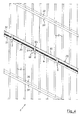
- the FIG. 1 The drawing shows in a view of a fence mesh 1, the central part is cut out for reasons of size of the representation.
- the fencing grid 1 consists of an intersecting arrangement of mutually parallel vertical bars 2 and mutually parallel horizontal bars 31. At their crossing points, the bars 2, 31 are connected to each other, usually welded. In this case, form the bars 2, 31 rectangular mesh, as is known from Zaungittern in itself. Left and right in FIG. 1 is in each case an end-side edge bar 20 is arranged, which is used in particular for connecting the Zaungitters 1 with fence posts, not shown here.
- Parallel to the horizontal individual bars 31 are in the example shown in FIG. 1 arranged in three different heights additional horizontal bars 31 at a relatively close distance from each other, each forming a grid bar pair 33, which forms a gap 34 between them.
- This gap 34 is dimensioned such that at least one cable-shaped conductor, which in FIG. 1 not shown, can be accommodated appropriately.
- FIG. 2 the drawing shows the fence grid 1 from FIG. 1 in an end view on the in FIG. 1 left front side. From bottom to top passing through the now visible only edge bar 20, behind which the vertical bars 2 extends congruent and thus in FIG. 2 lie invisibly.
- the individual horizontal bars 31 are arranged opposite each other at regular intervals. Alternatively you can the horizontal bars instead of each opposite each other and offset from each other and / or arranged at irregular intervals.
- the horizontal grid bar pairs 33 are arranged, which form between them in each case the gap 34.
- FIG. 3 the drawing is in FIG. 2 each circled detail III shown enlarged.
- the two horizontal bars 31, which form the grid bar pair 33 and which form the gap 34 between them arranged.
- a further grid bar 32 extends parallel to the horizontal bars 31 at an altitude which is centrally located here between the longitudinal axes of the two bars 31 of the grid bar pair 33.
- a cable-shaped conductor can be inserted properly and fixed in a suitable manner to be explained later.
- the parallel to the gap 34 extending grid bar 32 covers the gap 34 to the in FIG. 3 towards the left side.
- FIG. 4 a detail of a fence mesh 1 is shown in a front view, in which case an arrangement of two close to each other parallel, the grid bar pair 33 forming bars 31 is visible.
- a cable-shaped conductor 4 is inserted, for example, a sensor cable or a power line or the like.
- the cable-shaped conductor 4 is fixed in the intermediate space 34 by holding elements 5 attached at intervals.
- the holding elements 5 are designed as elastic-flexible clamps. These have each end a curved support arm 53, which lies around each one of the two bars 31 of the grid bar pair 33 over approximately half the circumference around.
- a region of the holding element 5 between the two holding arms 53 forms a fixing part 54 which rests against the cable-shaped conductor 4 and fixes and secures it in the intermediate space 34.
- the holding elements 5 are preferably made of a suitable plastic; Alternatively, they may also consist of a suitable resilient or deformable metal.
- a respective horizontal grid bar 31 is attached to the side of the fence fence 1 facing the observer, and a further horizontal grid bar 32 is attached to the side of the fence fence 1 facing away from the observer at the same height. Also in the amount of the grid bar pair 33, a further horizontal individual grid bar 32 is arranged on the opposite side of this Zaungitters 1, the in FIG. 4 is largely obscured.
- FIG. 5 the drawing shows the detail of the fence grid 1 FIG. 4 from the other side as well as in a somewhat enlarged representation.
- the view now falls on the individual horizontal grid bar 32, on the opposite side on the other side of Zaungitters 1, the lattice rod pair 33 from the two parallel bars 31 is mounted.
- the intermediate space 34 between the two bars 31 of the grid bar pair 33 again runs the cable-shaped conductor 4, which is secured in its position by the holding elements 5.
- FIG. 6 the drawing shows in the same representation as the FIG. 4 a section of a fence mesh 1, which coincides with the fence mesh 1 in FIG. 4 is executed; to the description of which reference is made.
- the holding element 5 is designed here as a latching element with two latching on one of the vertical bars 2 attachable holding arms 52.
- a fixing member 54 integrally connecting the holding arms 52 engages over the two horizontal bars 31 of the grid bar pair 33 and the cable-shaped conductor 4 arranged in the intermediate space 34 therebetween. This fixes and holds the cable-shaped conductor 4 in the space 34.
- the holding element 5 can be attached without tools and, if necessary, can be detached again from the fence grid 1 without damage.
- the holding element 5 is for example an injection-molded part made of plastic, which is thus inexpensive to produce as a mass part.
- FIG. 7 shows in the same representation as the FIG. 5 the fence mesh 1 with the holding element 5 from FIG. 6 ,
- the fence outer side which is created by the fence-type gratings 1
- the individual horizontal grid bar 32 is visible in opposition to the bars 31 of the grid-bar pair 33 with the cable-shaped conductor 4 arranged therebetween.
- the holding element 5 is placed with its holder arms 52 latching on one of the vertical bars 2.
- the holding element 5 is first applied with its holder arms 52 to the spine 2 and then latched by exerting a force acting in the direction of the grating bar 2 force on the spine 2.
- the holding element 5 thus has a mode of action in the manner of a pressure clamp.
- FIGS. 8 and 9 The drawing shows a third embodiment of the holding element 5 is shown again in two different views, the views according to the FIGS. 4 and 6 or 5 and 7 respectively.
- the holding element 5 has two holder arms 52 and a fixing part 54 for fixing the cable-shaped conductor 4 between the two horizontal bars 31 of the grid bar pair 33.
- the holder arms 52 are here designed so that they by a limited rotational movement of the support member 5 about a horizontal, perpendicular to Zaungitterebene axis in and out of engagement with the vertical grid bar 2 can be brought.
- the connection is also a detent connection here.
- ⁇ U> REFERENCE LIST ⁇ / u> character description 1 mesh fence 11 inside 12 outside 2 vertical bars 20 edge bars 31 horizontal bars inside 32 horizontal bars outside 33 Gitterstab pair 34 gap 4 cable-shaped conductor 5 retaining elements 52 Holding arms at 5 for 2 53 Holding arms at 5 for 31 54 Fixing part of 5
Landscapes
- Engineering & Computer Science (AREA)
- Architecture (AREA)
- Civil Engineering (AREA)
- Structural Engineering (AREA)
- Physics & Mathematics (AREA)
- General Physics & Mathematics (AREA)
- Fencing (AREA)
Applications Claiming Priority (1)
| Application Number | Priority Date | Filing Date | Title |
|---|---|---|---|
| DE202013100055U DE202013100055U1 (de) | 2013-01-07 | 2013-01-07 | Zaungitter, Zaun und Halteelement oder -profil |
Publications (2)
| Publication Number | Publication Date |
|---|---|
| EP2752536A2 true EP2752536A2 (fr) | 2014-07-09 |
| EP2752536A3 EP2752536A3 (fr) | 2018-07-18 |
Family
ID=47879118
Family Applications (1)
| Application Number | Title | Priority Date | Filing Date |
|---|---|---|---|
| EP13198262.1A Withdrawn EP2752536A3 (fr) | 2013-01-07 | 2013-12-19 | Treillis de clôture, clôture et élément ou profil de support |
Country Status (2)
| Country | Link |
|---|---|
| EP (1) | EP2752536A3 (fr) |
| DE (1) | DE202013100055U1 (fr) |
Cited By (1)
| Publication number | Priority date | Publication date | Assignee | Title |
|---|---|---|---|---|
| CN108240135A (zh) * | 2017-12-11 | 2018-07-03 | 国网山东省电力公司莒南县供电公司 | 可伸缩的电力安全围栏 |
Families Citing this family (2)
| Publication number | Priority date | Publication date | Assignee | Title |
|---|---|---|---|---|
| EP3808924A1 (fr) * | 2019-10-15 | 2021-04-21 | Intersig NV | Assemblage d'un grillage et d'un accessoire et methode correspondante |
| BE1027315B1 (nl) * | 2019-10-15 | 2020-12-21 | Intersig Nv | Hulpstuk en gerelateerde werkwijzen |
Citations (5)
| Publication number | Priority date | Publication date | Assignee | Title |
|---|---|---|---|---|
| DE8815756U1 (fr) | 1988-07-04 | 1989-02-09 | Adronit-Werk Hermann Aderhold Gmbh & Co, 5802 Wetter, De | |
| DE29612956U1 (de) | 1996-07-26 | 1997-11-20 | Adronit Verwaltungs Gmbh Co | Gitterzaun |
| DE102005055060B3 (de) | 2005-11-16 | 2007-03-15 | Draht-Bremer Gmbh | Sicherheitszaun |
| EP1862612A2 (fr) | 2006-06-02 | 2007-12-05 | Draht-Bremer GmbH | Dispositif de fixation pour câble de détection sur une clôture de sécurité |
| DE602004005567T2 (de) | 2004-02-13 | 2008-01-24 | Betafence Holding Nv | Zaunbau mit Zaunpfosten und daran befestigten flachen Gitterpaneele |
Family Cites Families (4)
| Publication number | Priority date | Publication date | Assignee | Title |
|---|---|---|---|---|
| DE29503595U1 (de) * | 1995-03-03 | 1995-04-27 | Ems Volker | Sicherheitszaun |
| FR2762919B1 (fr) * | 1997-04-30 | 1999-08-06 | Yves Guerineau | Cloture de securite constituee de treillis conducteurs |
| GB2482450A (en) * | 2009-05-08 | 2012-02-01 | Birmingham Barbed Tape Ltd | Modular fence panel |
| DE202010008194U1 (de) * | 2010-07-30 | 2011-01-20 | Haverkamp, Bernhard | Sicherheitszaun |
-
2013
- 2013-01-07 DE DE202013100055U patent/DE202013100055U1/de not_active Expired - Lifetime
- 2013-12-19 EP EP13198262.1A patent/EP2752536A3/fr not_active Withdrawn
Patent Citations (5)
| Publication number | Priority date | Publication date | Assignee | Title |
|---|---|---|---|---|
| DE8815756U1 (fr) | 1988-07-04 | 1989-02-09 | Adronit-Werk Hermann Aderhold Gmbh & Co, 5802 Wetter, De | |
| DE29612956U1 (de) | 1996-07-26 | 1997-11-20 | Adronit Verwaltungs Gmbh Co | Gitterzaun |
| DE602004005567T2 (de) | 2004-02-13 | 2008-01-24 | Betafence Holding Nv | Zaunbau mit Zaunpfosten und daran befestigten flachen Gitterpaneele |
| DE102005055060B3 (de) | 2005-11-16 | 2007-03-15 | Draht-Bremer Gmbh | Sicherheitszaun |
| EP1862612A2 (fr) | 2006-06-02 | 2007-12-05 | Draht-Bremer GmbH | Dispositif de fixation pour câble de détection sur une clôture de sécurité |
Cited By (2)
| Publication number | Priority date | Publication date | Assignee | Title |
|---|---|---|---|---|
| CN108240135A (zh) * | 2017-12-11 | 2018-07-03 | 国网山东省电力公司莒南县供电公司 | 可伸缩的电力安全围栏 |
| CN108240135B (zh) * | 2017-12-11 | 2019-10-18 | 国网山东省电力公司莒南县供电公司 | 可伸缩的电力安全围栏 |
Also Published As
| Publication number | Publication date |
|---|---|
| EP2752536A3 (fr) | 2018-07-18 |
| DE202013100055U1 (de) | 2013-02-08 |
Similar Documents
| Publication | Publication Date | Title |
|---|---|---|
| DE202012000092U1 (de) | Schrankengitter | |
| DE202006007690U1 (de) | Zaun aus Zaunpfosten und Gittermatten | |
| DE202010008501U1 (de) | Alarmgesichertes Zaunfeld | |
| EP2752536A2 (fr) | Treillis de clôture, clôture et élément ou profil de support | |
| DE102007002601A1 (de) | Zaunbefestigungssystem | |
| EP3274971B1 (fr) | Mât en treillis pour guider un câble de signal | |
| DE202006000073U1 (de) | Diebstahlsicherungsvorrichtung für eine Photovoltaikanlage | |
| DE102009037977A1 (de) | Absperrelement, insbesondere ein Bauzaun, eine Absperrschranke oder dgl., Vorrichtung zur Verkettung von Absperrelementen und Schwenkvorrichtung zwischen zwei Absperrelementen | |
| EP2497864A2 (fr) | Dispositif de formation de flancs de préférence érigeables | |
| EP1862612A2 (fr) | Dispositif de fixation pour câble de détection sur une clôture de sécurité | |
| DE3324153A1 (de) | Objektschutzgitter | |
| DE202020101933U1 (de) | Verbindungselement | |
| EP2982014B1 (fr) | Réalisation d'un type de protection pour appareils électriques et électroniques, en particulier pour armoires de distribution | |
| DE202011100030U1 (de) | Vorrichtung zur Verbindung und Befestigung von Gittermatten | |
| DE202010008194U1 (de) | Sicherheitszaun | |
| DE102005034105B4 (de) | Sicherungsvorrichtung | |
| EP2907763B1 (fr) | Revêtement mural doté de corbeilles en treillis métallique et corbeille en treillis métallique | |
| DE202013010191U1 (de) | Zaunsystem | |
| DE102018104314A1 (de) | Toranlage | |
| DE102012104607A1 (de) | Sichtschutzzaunmatte | |
| EP2644807A1 (fr) | Système de mise en place de clôture | |
| DE102012005210B4 (de) | Schutzzaunsystem | |
| DE202012005219U1 (de) | Wand aus wenigstens einem Wandelement und wenigstens einem Pfostenelement | |
| DE202004005544U1 (de) | Zaunstecksystem | |
| DE102016100467A1 (de) | Haltevorrichtung für die Enden zwischen die Gitterstäbe eines Stabgitterelementes eingeflochtener Wind- und/oder Sichtschutzprofile |
Legal Events
| Date | Code | Title | Description |
|---|---|---|---|
| 17P | Request for examination filed |
Effective date: 20131219 |
|
| AK | Designated contracting states |
Kind code of ref document: A2 Designated state(s): AL AT BE BG CH CY CZ DE DK EE ES FI FR GB GR HR HU IE IS IT LI LT LU LV MC MK MT NL NO PL PT RO RS SE SI SK SM TR |
|
| AX | Request for extension of the european patent |
Extension state: BA ME |
|
| PUAI | Public reference made under article 153(3) epc to a published international application that has entered the european phase |
Free format text: ORIGINAL CODE: 0009012 |
|
| RIC1 | Information provided on ipc code assigned before grant |
Ipc: F21V 33/00 20060101ALN20180303BHEP Ipc: G08B 13/12 20060101ALI20180303BHEP Ipc: E04H 17/16 20060101AFI20180303BHEP |
|
| PUAL | Search report despatched |
Free format text: ORIGINAL CODE: 0009013 |
|
| AK | Designated contracting states |
Kind code of ref document: A3 Designated state(s): AL AT BE BG CH CY CZ DE DK EE ES FI FR GB GR HR HU IE IS IT LI LT LU LV MC MK MT NL NO PL PT RO RS SE SI SK SM TR |
|
| AX | Request for extension of the european patent |
Extension state: BA ME |
|
| RIC1 | Information provided on ipc code assigned before grant |
Ipc: F21V 33/00 20060101ALN20180612BHEP Ipc: G08B 13/12 20060101ALI20180612BHEP Ipc: E04H 17/16 20060101AFI20180612BHEP |
|
| STAA | Information on the status of an ep patent application or granted ep patent |
Free format text: STATUS: THE APPLICATION IS DEEMED TO BE WITHDRAWN |
|
| 18D | Application deemed to be withdrawn |
Effective date: 20190119 |