EP2907763B1 - Revêtement mural doté de corbeilles en treillis métallique et corbeille en treillis métallique - Google Patents
Revêtement mural doté de corbeilles en treillis métallique et corbeille en treillis métallique Download PDFInfo
- Publication number
- EP2907763B1 EP2907763B1 EP14000539.8A EP14000539A EP2907763B1 EP 2907763 B1 EP2907763 B1 EP 2907763B1 EP 14000539 A EP14000539 A EP 14000539A EP 2907763 B1 EP2907763 B1 EP 2907763B1
- Authority
- EP
- European Patent Office
- Prior art keywords
- wire
- wire mesh
- metal wire
- wall cladding
- basket
- Prior art date
- Legal status (The legal status is an assumption and is not a legal conclusion. Google has not performed a legal analysis and makes no representation as to the accuracy of the status listed.)
- Not-in-force
Links
Images

Classifications
-
- E—FIXED CONSTRUCTIONS
- E04—BUILDING
- E04F—FINISHING WORK ON BUILDINGS, e.g. STAIRS, FLOORS
- E04F13/00—Coverings or linings, e.g. for walls or ceilings
- E04F13/07—Coverings or linings, e.g. for walls or ceilings composed of covering or lining elements; Sub-structures therefor; Fastening means therefor
- E04F13/08—Coverings or linings, e.g. for walls or ceilings composed of covering or lining elements; Sub-structures therefor; Fastening means therefor composed of a plurality of similar covering or lining elements
- E04F13/12—Coverings or linings, e.g. for walls or ceilings composed of covering or lining elements; Sub-structures therefor; Fastening means therefor composed of a plurality of similar covering or lining elements of metal or with an outer layer of metal or enameled metal
- E04F13/126—Coverings or linings, e.g. for walls or ceilings composed of covering or lining elements; Sub-structures therefor; Fastening means therefor composed of a plurality of similar covering or lining elements of metal or with an outer layer of metal or enameled metal with an outer layer of wire mesh, wire grid or the like, e.g. gabions
Definitions
- the invention relates to a wall paneling with wire mesh baskets according to the preamble of claim 1.
- a wall paneling is made DE 10 2004 063 846 A1 known.
- wire mesh baskets In order to be able to position the wire mesh baskets precisely, they are provided with suspension parts on their rear side, which are suspended in the support rails. In addition, located at the back of the wire mesh baskets spacers, which ensure that the hinged wire mesh baskets do not reach in an inclined position relative to the wall to be covered. It is thus a considerable technical effort required to mount the wall covering.
- the invention has the object of providing the generic wall paneling and the generic wire mesh basket in such a way that easy handling of the wire rack is possible, especially in the production of wall coverings.
- retaining rails are used, which are designed so that they also serve as Wegziehsperre and for receiving loads. Therefore, no separate components are required for these two different functions. With the attachment of the retaining rail on the wall Wegziehsperre and the load receiving part are already mounted accurately positioned so that only the wire mesh baskets must be hung with their suspension elements. The installation of a wall cladding is therefore very easy.
- the retaining rail serves the respective upper wire mesh basket as a pull-out barrier and as a spacer and the respective underlying wire mesh cage for receiving loads.
- the Wegziehsperre is formed by an angled upper edge of a fastening part of the retaining rail.
- the retaining rail is attached to the wall.
- the retaining rail can be formed in an advantageous manner by a flat rail, the upper edge is angled to form the Wegziehsperperre.
- the load receiving part is formed by the lower angled edge of the fastening part of the retaining rail.
- the support rail can thus be easily formed from a flat sheet metal part whose upper and lower edges are merely angled, which is possible in a simple manner.
- the Wegziehsperre and the load-receiving part are approximately parallel to each other and extend from the fastening part of obliquely upward.
- the fastening part of the retaining rail in its upper half, preferably in the upper third, at least one passage opening for a fastening screw, then the retaining rail can be mounted so that the adjoining the Wegziehsperre area of the fastening part under the load of the hinged wire mesh baskets not from the wall is bent away.
- the hooking elements used for hanging the wire mesh baskets are hook-shaped and made of a bent grid wire. From him, the hanging element can be easily and inexpensively finished.
- the suspension element has advantageously at the upper end over the wire mesh cage in the direction of the retaining rail projecting hanger. As a result, the wire mesh basket can be easily hooked into the retaining rail.
- Reliable securing of the suspension element on the wire mesh cage is achieved when the suspension element has a hook part at the lower end which engages around a transverse wire of the wire mesh cage. Under the load of the wire rack basket, the corresponding transverse wire is in the hook part of the hooking element, so that the hooking element is held captive on the wire mesh basket.
- the wire mesh of the wire mesh cage is made of stainless steel, so that the wall covering, which is usually outdoors, has a long life.
- the grid wire only has a diameter of ⁇ about 2.5 mm.
- the grid wire is preferably stainless steel, the use of a small wire diameter means that less material is needed for the grid wire so that the wire mesh basket, despite the use of stainless steel grid wires, is not significantly higher in price than conventional wire mesh baskets made of galvanized grid wires.
- wire mesh baskets can be handled by the user without the use of lifting equipment, so that even private users can easily erect wall coverings with such wire mesh baskets.
- the longitudinal sides extend horizontally. It has been found that in such an orientation of the rectangular grid openings, the filling of the wire mesh baskets is clearly visible even when the viewer looks from the side at a very oblique angle to the wall covering. In the case of rectangular grid openings, which are arranged vertically, essentially only the grid wires can be seen in such a case, but not the filling of the wire cage baskets.
- the distance between the Wegziehsperre and the load receiving part of the retaining rail is chosen so that the respective lower wire mesh basket can not be unmounted when the upper wire mesh basket is mounted.
- the retaining rail thus fulfills a further function, namely a safeguard against unhooking the wire mesh baskets in the assembled state. If the Wegziehsperre and the load receiving part would be provided on two separate support rails, then it would not be ensured that the safety catch is guaranteed in the assembly of the wall panel in any case. It would depend on the user how careful he is in this case, the two support rails mounted with the necessary distance to the facade. As a result of the inventive training these problems are prevented because with the attachment of the retaining rail on the facade of the distance between the Wegziehsperre and the load-receiving part is predetermined and can not be changed by the user.
- the wire mesh cage according to the invention is distinguished above all by its long service life and its low weight.
- the wire mesh basket can be handled very easily by home users, since its weight with filling is ⁇ about 25 kg. This is achieved by a corresponding compact design of the wire rack basket, for example, has a width and a height of 50 cm and a depth of, for example, only about 7 cm.
- the use of stainless steel for the grid wires ensures a long service life, especially in the outdoor use of the wire rack basket. Since the longitudinal sides of the grid openings extend horizontally at least in the front and thus the visible side of the wire rack, the filling of the wire mesh basket can be detected even with very oblique side view of the wire rack.
- the longitudinal wires are located on the side of the transverse wires facing the inside of the wire mesh basket.
- the one wire grid preferably forms the rear side of the wire mesh basket.
- the other wire grid is then formed to form the front, side and bottom of the wire rack.
- the wall cladding is formed by wire mesh baskets, which are characterized in that they are very narrow.
- the wire mesh basket has a width of 50 cm, a height of 50 cm and a depth of only 7 cm. These dimensions are not meant to be limiting and may deviate from the stated values. However, the depth of the wire mesh basket is much lower than in conventional wire mesh baskets used for wall coverings.
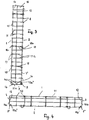
- the wire mesh basket has a front and a back 1, 2, which are interconnected by narrow end faces 3, 4 and a correspondingly narrow bottom 5.
- the back 2 which faces in the installed position of the wire rack a cover to be covered facade 6 ( Fig. 5 ), has longitudinally extending longitudinal wires 7, which are interconnected by horizontal transverse wires 8.
- the wires 7, 8 define rectangular grid openings 9, which are provided so that the longitudinal sides of these grid openings extend horizontally.
- the back 2 has at the two longitudinal edges in each case a longitudinal wire 7 '.
- the upper ends of the longitudinal wires 7, 7 ' are connected by an upper horizontal transverse wire 8. With their lower ends, the longitudinal wires 7, 7 'protrude downwards over the lower transverse wire 8.
- the front 1, the end faces 3, 4, which form the narrow sides of the wire rack basket, and the bottom 5 are formed by a further wire grid, which consists of vertically extending longitudinal wires 10 and these connecting, horizontally extending transverse wires 11.
- the upper ends of the longitudinal wires 10 are interconnected by an upper cross wire 11, while the lower ends of the longitudinal wires 10 project beyond the lower cross wire 11.
- the ends 11 a, 11 b ( Fig. 4 ) of the horizontal transverse wires 11 bent at right angles. At their free ends, the transverse wire ends 11 a, 11 b are bent in a hook shape, so that hooks 11 a ', 11 b' are formed. They surround the end-side longitudinal wires 7 'of the back 2.
- the horizontal transverse wire ends 11 a, 11 b are connected by a longitudinal wire 12 together. It is provided so as not to project beyond the upper and lower cross wire ends 11a, 11b ( Fig. 3 ).
- the longitudinal wire 12 stiffens the narrow sides 3, 4, so that they have sufficient strength and rigidity.
- the longitudinal wires 10 and the transverse wires 11 define rectangular grid openings 13 (FIG. Fig. 1 ), whose longitudinal sides extend horizontally.
- the grid openings 13 are advantageously the same size as the grid openings 9 of the front side 1.
- the longitudinal wire 12 in the narrow sides 3, 4 is arranged off-center in the embodiment, whereby the narrow sides have two different sized grid openings 14, 15 ( Fig. 3 ).
- the grid opening 14 has a square outline, while the grid opening 15 has a rectangular outline, this grid opening being provided so that the longitudinal side is horizontal.
- the grid opening 15 connects to the back 2 and the grid opening 14 to the front side 1 of the wire rack.
- the rectangular grid opening 15 can also connect to the front side 1 and the square grid opening 14 to the rear side 2. Furthermore, it is possible that the longitudinal wire 12 is also provided in half the width of the narrow sides 3, 4.
- the longitudinal wires 10 project with their lower ends over the lower transverse wire 11 before ( Fig. 3 ).
- This projecting end 10a of the longitudinal wires 10 is bent at right angles and formed at the free end to a hook 10a '.
- the hooks 10a engage around the lower cross wire 8 of the back 2 ( Fig. 3 ).
- the hooks 11a 'of the transverse wires 11 embrace the end-side longitudinal wires 7' of the back 2 from the outside, so that the ends of these hooks are directed inwardly into the wire mesh cage. The hook ends thus do not lead to injuries when handling the wire rack.
- the bent longitudinal wire ends 10a are interconnected by transverse wires 16 which extend horizontally and whose free ends 16a, 16b are bent at right angles upwards.
- the free transverse wire ends 16a, 16b are equal to the narrow sides 3, 4 of the wire rack.
- the transverse wires 16 are provided so that one transverse wire 16 lies approximately half the width of the narrow side 3, 4 and the other transverse wire 16 is close to the front side 1 of the wire mesh basket.
- the bent longitudinal wire ends 10a and the transverse wires 16 form the bottom 5 of the wire mesh basket and define grid openings 17 which have a rectangular outline. Their long sides extend horizontally.
- the grid openings 17 are due to the arrangement of the transverse wires 16 of different sizes.
- the wire mesh basket is formed in the manner described only by two wire mesh, which are connected to each other via the hooks 10a ', 11a', 11 b 'of the longitudinal and transverse wires 10, 11 of the front and the narrow sides 3, 4 forming wire grid.
- the wire mesh basket can be made simple and inexpensive.
- the front 1 and the back 2 are connected by spacers 18 which are distributed over the height and length of the wire rack basket.
- the spacers 18 are formed by wires whose two ends 18a, 18b are formed into hooks with which the spacers 18 are suspended in transverse wires 8, 11 in the front 1 and in the back 2. So that the spacers 18 can not slip along the transverse wires, one hook 18a is suspended at the point of intersection of the corresponding longitudinal wire 10 and transverse wire 11.
- the spacers 18 prevent the front 1 and the back 2 bulge outwards when the wire mesh basket is filled.
- the wire mesh basket Since the wire mesh basket has only a very small depth, it also has only a small receiving volume, so that the filled wire mesh basket has only low weight. It is only about 20 to 25 kg. Therefore, the wire mesh basket filled with stones can be transported and mounted by the user without lifting equipment. Therefore, the wire mesh basket is ideal for do-it-yourselfers who can mount the wall panel themselves.
- the wires of the wire mesh basket are advantageously made of corrosion-resistant material, in particular stainless steel, so that the wire mesh basket can be easily used outdoors without corrosion problems are to be feared.
- a relatively thin wire can be used, for example, has only a wire diameter of 2.5 mm. Because of this small wire diameter, the wireframe basket requires less wire material, so the cost of such a wireframe basket with stainless steel wires is almost the same as a wire mesh basket whose bars are made of galvanized steel.
- the horizontal orientation of the grid openings 13 in the front 1 has an effect on the appearance of the wire rack when viewed from a very small angle from the side.
- the horizontal orientation of the grid openings means that despite this flat angle, the stones in the wire mesh basket can be seen. If the rectangular grid openings are aligned vertically, then only the wires in the front 1 are visible in this lateral flat viewing angle, but not the stones located in the wire mesh basket.
- the wire mesh cage is designed so that the horizontal transverse wires are on the outside, while the vertically extending L'Harsdrähte are attached to the inside of the transverse wires in the crossing points. This arrangement of the grid wires helps, in conjunction with the horizontal alignment of the grid openings at a flat view, the stones in the wire mesh basket are clearly visible.
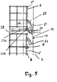
- the wire mesh baskets are designed so that in each case two superimposed wire mesh baskets can be fastened to a common retaining rail 19 ( Fig. 5 ).
- the retaining rail 19 has a flat fastening part 20 which rests flat in the installed position on the facade 6 of the wall to be clad. From the upper and lower edge of the fastening part 20 is in each case at least one suspension part 21, 22 from. Both suspension parts are advantageously formed integrally with the fastening part 20 and extend parallel to each other obliquely upwards.
- the hooking parts 21, 22 may extend over the length of the fastening part 20. But it is also possible that the fastening part 20 is longer than the hooking parts 21, 22nd
- the retaining rail 19 may extend over more than the width of the wire mesh basket, for example, over two or more adjacent to each other on the facade 6 to be arranged wire mesh baskets.
- the wire mesh baskets along the support rail 19 can optimally bring into the required installation position.
- the retaining rails 19 are fastened by one or more fastening screws 23 on the facade 6.
- corresponding hooks 24 are provided on the back 2. They are the same design and each bent from a wire.
- the suspension hook 24 is based on the Fig. 2 and 5 described in more detail.
- the suspension hook 24 ( Fig. 2 . 5 ) has a Einitatiteil 25, which is U-shaped and in the mounted position, the upper Ein fatigueteil 21 of the retaining rail 19 overlaps.
- the U-shaped suspension part 25 is at an acute angle to a fastening part 26, which has two legs 26a lying parallel to one another in a common plane.
- the lower ends of the legs 26a are hook-shaped and embrace one of the transverse wires 8 of the back 2 from the outside.
- one leg 27a of the hook 27 is angled outwardly at an obtuse angle relative to the fastening part 26, so that the hook 27 can embrace the corresponding transverse wire 8 from the outside.
- the other leg 27b protrudes into the wire mesh basket, so that there is no risk of injury to the user during assembly.
- the hooks 24 is disposed on the back 2, that the hooking part 25 and the legs 27a of the hook portion 27 protrude beyond the back 2.
- Fig. 2 shows, the legs of the U-shaped Ein vonmaschines 25, the fastening part 26 and the hook portion 27 are each in a common plane.
- the fastening part 26 is located at mounted wire mesh basket approximately at the level of the longitudinal wires 7 of the back. 2
- the hooks 24 are provided near the top and near the bottom 5 of the wire rack. Depending on the width of the wire rack, two or more hooks 24 are provided near the top and bottom of the wire rack.
- the hooks 24 are advantageously fixedly connected to the corresponding grid wires; but they can also be hung loosely in the back 2.
- the hooks 24 are provided on the wire mesh baskets that two superimposed wire mesh baskets can be hooked into the common support rail 19 ( Fig. 5 ).
- the lower Ein fatiguemaschine 25 of upper wire rack basket are under the weight on the suspension part 21 of the support rail 19.
- the Ein fatigueteil 25 serves as Wegziehsperre for the wire rack basket, which ensures that the wire mesh basket comes with its lower portion with appropriate lateral load is not disengaged from the hooking part 21 of the support rail 19.
- the Ein skilleder 22 of the support rails 19 serve as load-receiving parts that receive the weight of the wire rack basket.
- the hook parts 27 embrace from outside the respective transverse wire 8 of the back 2, whereby a secure attachment of the wire mesh baskets to the support rails 19 is ensured.
- the retaining rail 19 is provided in the manner described both with the Wegziehsperre in the form of Ein rehabilitationmaschines 21 and with the load receiving part in the form of Ein fatigueers 22. Since this only a single component is provided, not only results in a simple and inexpensive production of the retaining rail 19, but also a simple installation that can be made by do-it-yourselfers.
- the distance between the Ein von too many 21, 22 is chosen so that the respective lower wire mesh basket can not be unhooked when the upper wire mesh basket is mounted.
- the retaining rail 19 thereby serves as a safeguard against unhooking the wire mesh baskets.
- the wall cladding formed from the wire mesh baskets has horizontally extending joints 28 (FIG. Fig. 5 ), which are formed between stacked wire mesh baskets.
- the width of these joints 28 is determined by the support rail 19 and can not be changed by the user.
- This horizontally extending joint 28 can be optimally designed with the retaining rail 19 with respect to the joint image of the wall cladding. Since the width of the joint 28 during assembly of the wall panel can not be changed, the optimum joint width between stacked wire mesh baskets is always maintained. That way it will be reliable and very easy to get a uniform joint pattern in the wall paneling.
- the position of the hooks 24 is chosen so that the retaining rail 19 may be formed as narrow as possible. This has advantages with regard to the rigidity of the retaining rail 19. If the fastening part 20 of the retaining rail 19 wide, then the wall paneling is unstable and sensitive to vibration. Thus, in such a configuration, the retaining rail 19 bulge forward under the weight of the wire mesh baskets. Also, vibrations can occur due to wind suction and wind pressure.
- the retaining rail 19 can not bulge forward under the weight of the wire mesh baskets. Also caused by wind suction and wind pressure possibly triggered vibrations of the retaining rail 19 and the hinged wire mesh baskets reliably.
- the wire mesh baskets can be placed on the support rail 19 that the Ein vonmaschine 21, 22 of the support rails 19 come with their free ends to the grid wires of the back 2 to the plant ( Fig. 5 ).
- a precise positioning of the wire mesh baskets relative to one another and to the facade 8 is achieved in a simple manner.
- the fastening screws 23 are provided in the upper region of the fastening part 20 of the retaining rail 19. This prevents that the fastening part 23 is bent away from the facade 6 under the load of the hinged wire mesh baskets.
- the fastening wrenches 23 are preferably provided with only a small distance from the transition of the fastening part 20 into the upper suspension part 21.
- wire mesh baskets have a low weight in the filled state, which is less than about 25 kg, for the support rail 19, a relatively thin steel part can be used.
- the obliquely upwardly bent-in suspension parts 21, 29 can safely receive the load without being bent down under the load relative to the fastening part 20.
- the filled wire mesh baskets Due to the low weight of the filled wire mesh baskets can be used for their attachment to the facade 6 normal brickwork. With an exemplary width and height of 50 cm, four wire mesh baskets per square meter can be installed.
- the wire mesh baskets are characterized by their very compact design and their low weight in the filled state. This makes it possible that even individuals can mount such wire mesh baskets as wall panels themselves. A hoist is not required for installation. Due to the low weight, the filled wire mesh baskets can be manually moved and mounted on the support rails 19. The support rails themselves can be easily attached to the masonry with the mounting screws 23. Due to the low weight is no special masonry, such as a concrete wall, required, so that the wall paneling can be attached to standard masonry.
- the lightweight design results in a weight per unit area of less than 100 kg / m 2 , while previously standard baskets have a basis weight of up to 240 kg / m 2 .
- Baskets with a basis weight of 210 to 240 kg / m 2 are only suitable for suspension on concrete walls.
- the low basis weight also allows the use of significantly thicker insulation, especially heat insulation, but also insulation for reflection sound.
Landscapes
- Engineering & Computer Science (AREA)
- Architecture (AREA)
- Civil Engineering (AREA)
- Structural Engineering (AREA)
- Pit Excavations, Shoring, Fill Or Stabilisation Of Slopes (AREA)
Claims (9)
- Revêtement mural doté de corbeilles en treillis métallique qui sont remplies de matériau, notamment de pierres et qui comportent des éléments d'accrochage (24) qui sont conçus en forme de crochets et qui sont formés par un fil de treillis métallique recourbé, par lesquels ils sont accrochés dans des dispositifs de suspension (19) qui peuvent se fixer sur un mur (6) à revêtir,
caractérisé en ce que le dispositif de suspension est un rail de support (19) qui comporte au moins un verrouillage anti-arrachement (21) et au moins une pièce de reprise de charge (22) qui sont superposées avec un écart, en ce que le verrouillage anti-arrachement (21) est formé par un bord supérieur coudé et la pièce de reprise de charge (22) est formée par un bord inférieur coudé d'une pièce de fixation (20) plate du rail de support (19), en ce que le verrouillage anti-arrachement (21) et la pièce de reprise de charge (22) sont approximativement situés à la parallèle l'un de l'autre et s'étendent en oblique vers le haut et en ce que la corbeille en treillis métallique respectivement supérieure repose par au moins un élément d'accrochage (24) sur le verrouillage anti-arrachement (21) et la corbeille en treillis métallique respectivement inférieure s'appuie par au moins un élément d'accrochage (24) sur la pièce de reprise de charge (22). - Revêtement mural selon la revendication 1,
caractérisé en ce que dans sa moitié supérieure, de préférence dans le tiers supérieur, la pièce de fixation (20) du rail de support (19) comporte au moins un orifice de passage pour une vis de fixation (23). - Revêtement mural selon la revendication 1 ou 2,
caractérisé en ce que sur l'extrémité supérieure, l'élément d'accrochage (24) comporte une pièce d'accrochage (25) saillant par-dessus la corbeille en treillis métallique dans la direction du rail de support (19). - Revêtement mural selon l'une quelconque des revendications 1 à 3,
caractérisé en ce que sur l'extrémité inférieure, l'élément d'accrochage (24) comporte une partie crochet (27) qui entoure un fil métallique transversal (8) de la corbeille en treillis métallique. - Revêtement mural selon l'une quelconque des revendications 1 à 4,
caractérisé en ce que le fil métallique (7, 8 ; 10, 11 ; 16, 17) du treillis est en acier inoxydable. - Revêtement mural selon l'une quelconque des revendications 1 à 5,
caractérisé en ce que le fil métallique (7, 8 ; 10, 11 ; 16, 17) du treillis a un diamètre de fil métallique ≤ à environ 2,5 mm. - Revêtement mural selon l'une quelconque des revendications 1 à 6,
caractérisé en ce que la corbeille en treillis métallique présente avec son remplissage un poids ≤ à environ 25 kg. - Revêtement mural selon l'une quelconque des revendications 1 à 7,
caractérisé en ce qu'au moins la face visible (1) de la corbeille en treillis métallique comporte des orifices de treillis (13) rectangulaires, dont les côtés longitudinaux s'étendent à l'horizontale. - Revêtement mural selon l'une quelconque des revendications 1 à 8,
caractérisé en ce que l'écart entre le verrouillage anti-arrachement (21) et la pièce de reprise de charge (22) du rail de support (9) est choisi de telle sorte que la corbeille en treillis métallique respectivement inférieure ne peut pas être décrochée lorsque la corbeille en treillis métallique respectivement supérieure est accrochée.
Priority Applications (1)
| Application Number | Priority Date | Filing Date | Title |
|---|---|---|---|
| EP14000539.8A EP2907763B1 (fr) | 2014-02-14 | 2014-02-14 | Revêtement mural doté de corbeilles en treillis métallique et corbeille en treillis métallique |
Applications Claiming Priority (1)
| Application Number | Priority Date | Filing Date | Title |
|---|---|---|---|
| EP14000539.8A EP2907763B1 (fr) | 2014-02-14 | 2014-02-14 | Revêtement mural doté de corbeilles en treillis métallique et corbeille en treillis métallique |
Publications (2)
| Publication Number | Publication Date |
|---|---|
| EP2907763A1 EP2907763A1 (fr) | 2015-08-19 |
| EP2907763B1 true EP2907763B1 (fr) | 2017-07-05 |
Family
ID=50150531
Family Applications (1)
| Application Number | Title | Priority Date | Filing Date |
|---|---|---|---|
| EP14000539.8A Not-in-force EP2907763B1 (fr) | 2014-02-14 | 2014-02-14 | Revêtement mural doté de corbeilles en treillis métallique et corbeille en treillis métallique |
Country Status (1)
| Country | Link |
|---|---|
| EP (1) | EP2907763B1 (fr) |
Families Citing this family (1)
| Publication number | Priority date | Publication date | Assignee | Title |
|---|---|---|---|---|
| FR3107911B1 (fr) * | 2020-03-03 | 2022-03-04 | Mineral Deco | Parement mural à base de pierres |
Family Cites Families (9)
| Publication number | Priority date | Publication date | Assignee | Title |
|---|---|---|---|---|
| US3621635A (en) * | 1970-03-02 | 1971-11-23 | Cement Enamel Dev Inc | Panel wall |
| DE3831517A1 (de) * | 1988-09-16 | 1990-03-22 | Schmidlin Hans | Fassadenunterkonstruktion |
| US5647695A (en) * | 1995-04-11 | 1997-07-15 | Hilfiker Pipe Company | Soil filled wall |
| ES1040162Y (es) * | 1998-05-13 | 1999-07-01 | Construcciones Desmontables Ta | Conjunto sustentador de placas de revestimiento a medios de soporte fijados a las fachadas y/o forjados de edificios. |
| GB0106081D0 (en) * | 2001-03-13 | 2001-05-02 | Granfit Holdings Ltd | Wall cladding fitting |
| US20030085188A1 (en) * | 2001-11-07 | 2003-05-08 | Lynk, Inc. | Hanging storage unit with shelves and hooks |
| DE20218181U1 (de) * | 2002-11-23 | 2003-03-27 | Rothfuss Thomas | Vorbau für Wände, wie Gebäudewände, Stützwände, Brüstungen, Stahlkonstruktionen und dgl. |
| DE102004063846B4 (de) * | 2004-12-28 | 2015-03-05 | Thomas Rothfuss | Grünwandkorb |
| DE202005010395U1 (de) * | 2005-07-01 | 2005-09-08 | Rothfuss, Thomas | Aufhängevorrichtung für eine Fassadenverkleidung mit Drahtgitterkörben |
-
2014
- 2014-02-14 EP EP14000539.8A patent/EP2907763B1/fr not_active Not-in-force
Also Published As
| Publication number | Publication date |
|---|---|
| EP2907763A1 (fr) | 2015-08-19 |
Similar Documents
| Publication | Publication Date | Title |
|---|---|---|
| EP2354368B1 (fr) | Etrier de fixation pour isolations murales | |
| EP2499311B1 (fr) | Grille de protection latérale et système de protection latérale | |
| DE202020104198U1 (de) | Baugerüst | |
| EP3231962B1 (fr) | Sécurité anti-chute pour des personnes comprenant une plaque de sécurité dotée de griffes | |
| DE102004049681B4 (de) | Erdbebensicheres Serverrack | |
| DE202010010148U1 (de) | Gerüststütze für eine Gabione | |
| EP2798133B1 (fr) | Panneau pour un système de coffrage de plafond et système de coffrage de plafond | |
| DE102007023501B4 (de) | Geländeranlage mit eingeschlossenem Zaun | |
| DE102021004490A1 (de) | Modulgerüst sowie Modulgerüstriegel für ein solches | |
| AT390108B (de) | Schutzvorrichtung fuer metallgerueste | |
| DE202020103146U1 (de) | Vorrichtung zur Anbringung von Absturzsicherungen an Baugerüsten | |
| DE202020004844U1 (de) | Distanzstück für eine Schalung | |
| EP2907763B1 (fr) | Revêtement mural doté de corbeilles en treillis métallique et corbeille en treillis métallique | |
| EP2305889B1 (fr) | Corbeille en fil métallique et entretoise pour l'utilisation dans des corbeilles en fil métallique | |
| DE202008015170U1 (de) | Wandhalterung für Fest- bzw. Bierzeltgarnituren | |
| EP2975193A1 (fr) | Système d'échafaudage, dispositif de raccordement pour le raccordement de deux armatures d'un système d'échafaudage et dispositif d'empêchement de soulèvement permettant d'empêcher le soulèvement d'une armature d'un verrou longitudinal ou transversal d'un système d'échafaudage | |
| EP1739250A2 (fr) | Support permettant de suspendre un revêtement de façade avec paniers en fils metalliques | |
| EP2312062B1 (fr) | Gabione | |
| EP2644807A1 (fr) | Système de mise en place de clôture | |
| DE4204638A1 (de) | Vorrichtung zur schalldaemmung in raeumen | |
| DE4405977C2 (de) | Konsole für die Abstützung einer Gerüstbühne | |
| DE1918773C3 (de) | Aus Bauteilen zusammensetzbare, aufhängbare und in Abschnitten verlängerbare Arbeltsbühne | |
| AT14393U1 (de) | Schneefangsystem für Glasdächer | |
| DE19718650A1 (de) | Im Bauwesen zu verwendende Vorrichtung zur Bildung eines Konsolgerüstelements | |
| DE202009015200U1 (de) | Balkonkonstruktion |
Legal Events
| Date | Code | Title | Description |
|---|---|---|---|
| PUAI | Public reference made under article 153(3) epc to a published international application that has entered the european phase |
Free format text: ORIGINAL CODE: 0009012 |
|
| AK | Designated contracting states |
Kind code of ref document: A1 Designated state(s): AL AT BE BG CH CY CZ DE DK EE ES FI FR GB GR HR HU IE IS IT LI LT LU LV MC MK MT NL NO PL PT RO RS SE SI SK SM TR |
|
| AX | Request for extension of the european patent |
Extension state: BA ME |
|
| RIN1 | Information on inventor provided before grant (corrected) |
Inventor name: BECKERT, MANFRED |
|
| RIN1 | Information on inventor provided before grant (corrected) |
Inventor name: BECKERT, MANFRED |
|
| 17P | Request for examination filed |
Effective date: 20160219 |
|
| RBV | Designated contracting states (corrected) |
Designated state(s): AL AT BE BG CH CY CZ DE DK EE ES FI FR GB GR HR HU IE IS IT LI LT LU LV MC MK MT NL NO PL PT RO RS SE SI SK SM TR |
|
| GRAP | Despatch of communication of intention to grant a patent |
Free format text: ORIGINAL CODE: EPIDOSNIGR1 |
|
| RAP1 | Party data changed (applicant data changed or rights of an application transferred) |
Owner name: AXEL FRIEDHOFF GMBH & CO. KG |
|
| INTG | Intention to grant announced |
Effective date: 20170124 |
|
| GRAS | Grant fee paid |
Free format text: ORIGINAL CODE: EPIDOSNIGR3 |
|
| GRAA | (expected) grant |
Free format text: ORIGINAL CODE: 0009210 |
|
| AK | Designated contracting states |
Kind code of ref document: B1 Designated state(s): AL AT BE BG CH CY CZ DE DK EE ES FI FR GB GR HR HU IE IS IT LI LT LU LV MC MK MT NL NO PL PT RO RS SE SI SK SM TR |
|
| REG | Reference to a national code |
Ref country code: GB Ref legal event code: FG4D Free format text: NOT ENGLISH |
|
| REG | Reference to a national code |
Ref country code: CH Ref legal event code: EP |
|
| REG | Reference to a national code |
Ref country code: AT Ref legal event code: REF Ref document number: 906417 Country of ref document: AT Kind code of ref document: T Effective date: 20170715 |
|
| REG | Reference to a national code |
Ref country code: IE Ref legal event code: FG4D Free format text: LANGUAGE OF EP DOCUMENT: GERMAN |
|
| REG | Reference to a national code |
Ref country code: DE Ref legal event code: R096 Ref document number: 502014004453 Country of ref document: DE |
|
| REG | Reference to a national code |
Ref country code: CH Ref legal event code: NV Representative=s name: TROESCH SCHEIDEGGER WERNER AG, CH |
|
| REG | Reference to a national code |
Ref country code: NL Ref legal event code: FP |
|
| REG | Reference to a national code |
Ref country code: LT Ref legal event code: MG4D |
|
| REG | Reference to a national code |
Ref country code: FR Ref legal event code: PLFP Year of fee payment: 5 |
|
| PG25 | Lapsed in a contracting state [announced via postgrant information from national office to epo] |
Ref country code: SE Free format text: LAPSE BECAUSE OF FAILURE TO SUBMIT A TRANSLATION OF THE DESCRIPTION OR TO PAY THE FEE WITHIN THE PRESCRIBED TIME-LIMIT Effective date: 20170705 Ref country code: NO Free format text: LAPSE BECAUSE OF FAILURE TO SUBMIT A TRANSLATION OF THE DESCRIPTION OR TO PAY THE FEE WITHIN THE PRESCRIBED TIME-LIMIT Effective date: 20171005 Ref country code: HR Free format text: LAPSE BECAUSE OF FAILURE TO SUBMIT A TRANSLATION OF THE DESCRIPTION OR TO PAY THE FEE WITHIN THE PRESCRIBED TIME-LIMIT Effective date: 20170705 Ref country code: LT Free format text: LAPSE BECAUSE OF FAILURE TO SUBMIT A TRANSLATION OF THE DESCRIPTION OR TO PAY THE FEE WITHIN THE PRESCRIBED TIME-LIMIT Effective date: 20170705 Ref country code: FI Free format text: LAPSE BECAUSE OF FAILURE TO SUBMIT A TRANSLATION OF THE DESCRIPTION OR TO PAY THE FEE WITHIN THE PRESCRIBED TIME-LIMIT Effective date: 20170705 |
|
| PG25 | Lapsed in a contracting state [announced via postgrant information from national office to epo] |
Ref country code: LV Free format text: LAPSE BECAUSE OF FAILURE TO SUBMIT A TRANSLATION OF THE DESCRIPTION OR TO PAY THE FEE WITHIN THE PRESCRIBED TIME-LIMIT Effective date: 20170705 Ref country code: IS Free format text: LAPSE BECAUSE OF FAILURE TO SUBMIT A TRANSLATION OF THE DESCRIPTION OR TO PAY THE FEE WITHIN THE PRESCRIBED TIME-LIMIT Effective date: 20171105 Ref country code: RS Free format text: LAPSE BECAUSE OF FAILURE TO SUBMIT A TRANSLATION OF THE DESCRIPTION OR TO PAY THE FEE WITHIN THE PRESCRIBED TIME-LIMIT Effective date: 20170705 Ref country code: PL Free format text: LAPSE BECAUSE OF FAILURE TO SUBMIT A TRANSLATION OF THE DESCRIPTION OR TO PAY THE FEE WITHIN THE PRESCRIBED TIME-LIMIT Effective date: 20170705 Ref country code: BG Free format text: LAPSE BECAUSE OF FAILURE TO SUBMIT A TRANSLATION OF THE DESCRIPTION OR TO PAY THE FEE WITHIN THE PRESCRIBED TIME-LIMIT Effective date: 20171005 Ref country code: GR Free format text: LAPSE BECAUSE OF FAILURE TO SUBMIT A TRANSLATION OF THE DESCRIPTION OR TO PAY THE FEE WITHIN THE PRESCRIBED TIME-LIMIT Effective date: 20171006 Ref country code: ES Free format text: LAPSE BECAUSE OF FAILURE TO SUBMIT A TRANSLATION OF THE DESCRIPTION OR TO PAY THE FEE WITHIN THE PRESCRIBED TIME-LIMIT Effective date: 20170705 |
|
| REG | Reference to a national code |
Ref country code: DE Ref legal event code: R097 Ref document number: 502014004453 Country of ref document: DE |
|
| PG25 | Lapsed in a contracting state [announced via postgrant information from national office to epo] |
Ref country code: DK Free format text: LAPSE BECAUSE OF FAILURE TO SUBMIT A TRANSLATION OF THE DESCRIPTION OR TO PAY THE FEE WITHIN THE PRESCRIBED TIME-LIMIT Effective date: 20170705 Ref country code: CZ Free format text: LAPSE BECAUSE OF FAILURE TO SUBMIT A TRANSLATION OF THE DESCRIPTION OR TO PAY THE FEE WITHIN THE PRESCRIBED TIME-LIMIT Effective date: 20170705 Ref country code: RO Free format text: LAPSE BECAUSE OF FAILURE TO SUBMIT A TRANSLATION OF THE DESCRIPTION OR TO PAY THE FEE WITHIN THE PRESCRIBED TIME-LIMIT Effective date: 20170705 |
|
| PLBE | No opposition filed within time limit |
Free format text: ORIGINAL CODE: 0009261 |
|
| STAA | Information on the status of an ep patent application or granted ep patent |
Free format text: STATUS: NO OPPOSITION FILED WITHIN TIME LIMIT |
|
| PG25 | Lapsed in a contracting state [announced via postgrant information from national office to epo] |
Ref country code: IT Free format text: LAPSE BECAUSE OF FAILURE TO SUBMIT A TRANSLATION OF THE DESCRIPTION OR TO PAY THE FEE WITHIN THE PRESCRIBED TIME-LIMIT Effective date: 20170705 Ref country code: EE Free format text: LAPSE BECAUSE OF FAILURE TO SUBMIT A TRANSLATION OF THE DESCRIPTION OR TO PAY THE FEE WITHIN THE PRESCRIBED TIME-LIMIT Effective date: 20170705 Ref country code: SK Free format text: LAPSE BECAUSE OF FAILURE TO SUBMIT A TRANSLATION OF THE DESCRIPTION OR TO PAY THE FEE WITHIN THE PRESCRIBED TIME-LIMIT Effective date: 20170705 Ref country code: SM Free format text: LAPSE BECAUSE OF FAILURE TO SUBMIT A TRANSLATION OF THE DESCRIPTION OR TO PAY THE FEE WITHIN THE PRESCRIBED TIME-LIMIT Effective date: 20170705 |
|
| 26N | No opposition filed |
Effective date: 20180406 |
|
| PG25 | Lapsed in a contracting state [announced via postgrant information from national office to epo] |
Ref country code: SI Free format text: LAPSE BECAUSE OF FAILURE TO SUBMIT A TRANSLATION OF THE DESCRIPTION OR TO PAY THE FEE WITHIN THE PRESCRIBED TIME-LIMIT Effective date: 20170705 |
|
| PG25 | Lapsed in a contracting state [announced via postgrant information from national office to epo] |
Ref country code: MT Free format text: LAPSE BECAUSE OF FAILURE TO SUBMIT A TRANSLATION OF THE DESCRIPTION OR TO PAY THE FEE WITHIN THE PRESCRIBED TIME-LIMIT Effective date: 20170705 Ref country code: MC Free format text: LAPSE BECAUSE OF FAILURE TO SUBMIT A TRANSLATION OF THE DESCRIPTION OR TO PAY THE FEE WITHIN THE PRESCRIBED TIME-LIMIT Effective date: 20170705 |
|
| GBPC | Gb: european patent ceased through non-payment of renewal fee |
Effective date: 20180214 |
|
| REG | Reference to a national code |
Ref country code: IE Ref legal event code: MM4A |
|
| REG | Reference to a national code |
Ref country code: BE Ref legal event code: MM Effective date: 20180228 |
|
| PG25 | Lapsed in a contracting state [announced via postgrant information from national office to epo] |
Ref country code: IE Free format text: LAPSE BECAUSE OF NON-PAYMENT OF DUE FEES Effective date: 20180214 |
|
| PG25 | Lapsed in a contracting state [announced via postgrant information from national office to epo] |
Ref country code: GB Free format text: LAPSE BECAUSE OF NON-PAYMENT OF DUE FEES Effective date: 20180214 Ref country code: BE Free format text: LAPSE BECAUSE OF NON-PAYMENT OF DUE FEES Effective date: 20180228 |
|
| PGFP | Annual fee paid to national office [announced via postgrant information from national office to epo] |
Ref country code: LU Payment date: 20190214 Year of fee payment: 6 Ref country code: NL Payment date: 20190227 Year of fee payment: 6 |
|
| PGFP | Annual fee paid to national office [announced via postgrant information from national office to epo] |
Ref country code: FR Payment date: 20190125 Year of fee payment: 6 Ref country code: CH Payment date: 20190128 Year of fee payment: 6 |
|
| PGFP | Annual fee paid to national office [announced via postgrant information from national office to epo] |
Ref country code: DE Payment date: 20190425 Year of fee payment: 6 |
|
| PG25 | Lapsed in a contracting state [announced via postgrant information from national office to epo] |
Ref country code: TR Free format text: LAPSE BECAUSE OF FAILURE TO SUBMIT A TRANSLATION OF THE DESCRIPTION OR TO PAY THE FEE WITHIN THE PRESCRIBED TIME-LIMIT Effective date: 20170705 |
|
| REG | Reference to a national code |
Ref country code: AT Ref legal event code: MM01 Ref document number: 906417 Country of ref document: AT Kind code of ref document: T Effective date: 20190214 |
|
| PG25 | Lapsed in a contracting state [announced via postgrant information from national office to epo] |
Ref country code: AT Free format text: LAPSE BECAUSE OF NON-PAYMENT OF DUE FEES Effective date: 20190214 |
|
| PG25 | Lapsed in a contracting state [announced via postgrant information from national office to epo] |
Ref country code: PT Free format text: LAPSE BECAUSE OF FAILURE TO SUBMIT A TRANSLATION OF THE DESCRIPTION OR TO PAY THE FEE WITHIN THE PRESCRIBED TIME-LIMIT Effective date: 20170705 |
|
| PG25 | Lapsed in a contracting state [announced via postgrant information from national office to epo] |
Ref country code: HU Free format text: LAPSE BECAUSE OF FAILURE TO SUBMIT A TRANSLATION OF THE DESCRIPTION OR TO PAY THE FEE WITHIN THE PRESCRIBED TIME-LIMIT; INVALID AB INITIO Effective date: 20140214 Ref country code: CY Free format text: LAPSE BECAUSE OF FAILURE TO SUBMIT A TRANSLATION OF THE DESCRIPTION OR TO PAY THE FEE WITHIN THE PRESCRIBED TIME-LIMIT Effective date: 20170705 Ref country code: MK Free format text: LAPSE BECAUSE OF NON-PAYMENT OF DUE FEES Effective date: 20170705 |
|
| PG25 | Lapsed in a contracting state [announced via postgrant information from national office to epo] |
Ref country code: AL Free format text: LAPSE BECAUSE OF FAILURE TO SUBMIT A TRANSLATION OF THE DESCRIPTION OR TO PAY THE FEE WITHIN THE PRESCRIBED TIME-LIMIT Effective date: 20170705 |
|
| REG | Reference to a national code |
Ref country code: DE Ref legal event code: R119 Ref document number: 502014004453 Country of ref document: DE |
|
| REG | Reference to a national code |
Ref country code: CH Ref legal event code: PL |
|
| REG | Reference to a national code |
Ref country code: NL Ref legal event code: MM Effective date: 20200301 |
|
| PG25 | Lapsed in a contracting state [announced via postgrant information from national office to epo] |
Ref country code: LU Free format text: LAPSE BECAUSE OF NON-PAYMENT OF DUE FEES Effective date: 20200214 |
|
| PG25 | Lapsed in a contracting state [announced via postgrant information from national office to epo] |
Ref country code: LI Free format text: LAPSE BECAUSE OF NON-PAYMENT OF DUE FEES Effective date: 20200229 Ref country code: CH Free format text: LAPSE BECAUSE OF NON-PAYMENT OF DUE FEES Effective date: 20200229 |
|
| PG25 | Lapsed in a contracting state [announced via postgrant information from national office to epo] |
Ref country code: NL Free format text: LAPSE BECAUSE OF NON-PAYMENT OF DUE FEES Effective date: 20200301 |
|
| PG25 | Lapsed in a contracting state [announced via postgrant information from national office to epo] |
Ref country code: DE Free format text: LAPSE BECAUSE OF NON-PAYMENT OF DUE FEES Effective date: 20200901 Ref country code: FR Free format text: LAPSE BECAUSE OF NON-PAYMENT OF DUE FEES Effective date: 20200229 |