EP2907763B1 - Wall cladding with metal wire baskets and metal wire baskets - Google Patents
Wall cladding with metal wire baskets and metal wire baskets Download PDFInfo
- Publication number
- EP2907763B1 EP2907763B1 EP14000539.8A EP14000539A EP2907763B1 EP 2907763 B1 EP2907763 B1 EP 2907763B1 EP 14000539 A EP14000539 A EP 14000539A EP 2907763 B1 EP2907763 B1 EP 2907763B1
- Authority
- EP
- European Patent Office
- Prior art keywords
- wire
- wire mesh
- metal wire
- wall cladding
- basket
- Prior art date
- Legal status (The legal status is an assumption and is not a legal conclusion. Google has not performed a legal analysis and makes no representation as to the accuracy of the status listed.)
- Not-in-force
Links
Images

Classifications
-
- E—FIXED CONSTRUCTIONS
- E04—BUILDING
- E04F—FINISHING WORK ON BUILDINGS, e.g. STAIRS, FLOORS
- E04F13/00—Coverings or linings, e.g. for walls or ceilings
- E04F13/07—Coverings or linings, e.g. for walls or ceilings composed of covering or lining elements; Sub-structures therefor; Fastening means therefor
- E04F13/08—Coverings or linings, e.g. for walls or ceilings composed of covering or lining elements; Sub-structures therefor; Fastening means therefor composed of a plurality of similar covering or lining elements
- E04F13/12—Coverings or linings, e.g. for walls or ceilings composed of covering or lining elements; Sub-structures therefor; Fastening means therefor composed of a plurality of similar covering or lining elements of metal or with an outer layer of metal or enameled metal
- E04F13/126—Coverings or linings, e.g. for walls or ceilings composed of covering or lining elements; Sub-structures therefor; Fastening means therefor composed of a plurality of similar covering or lining elements of metal or with an outer layer of metal or enameled metal with an outer layer of wire mesh, wire grid or the like, e.g. gabions
Definitions
- the invention relates to a wall paneling with wire mesh baskets according to the preamble of claim 1.
- a wall paneling is made DE 10 2004 063 846 A1 known.
- wire mesh baskets In order to be able to position the wire mesh baskets precisely, they are provided with suspension parts on their rear side, which are suspended in the support rails. In addition, located at the back of the wire mesh baskets spacers, which ensure that the hinged wire mesh baskets do not reach in an inclined position relative to the wall to be covered. It is thus a considerable technical effort required to mount the wall covering.
- the invention has the object of providing the generic wall paneling and the generic wire mesh basket in such a way that easy handling of the wire rack is possible, especially in the production of wall coverings.
- retaining rails are used, which are designed so that they also serve as Wegziehsperre and for receiving loads. Therefore, no separate components are required for these two different functions. With the attachment of the retaining rail on the wall Wegziehsperre and the load receiving part are already mounted accurately positioned so that only the wire mesh baskets must be hung with their suspension elements. The installation of a wall cladding is therefore very easy.
- the retaining rail serves the respective upper wire mesh basket as a pull-out barrier and as a spacer and the respective underlying wire mesh cage for receiving loads.
- the Wegziehsperre is formed by an angled upper edge of a fastening part of the retaining rail.
- the retaining rail is attached to the wall.
- the retaining rail can be formed in an advantageous manner by a flat rail, the upper edge is angled to form the Wegziehsperperre.
- the load receiving part is formed by the lower angled edge of the fastening part of the retaining rail.
- the support rail can thus be easily formed from a flat sheet metal part whose upper and lower edges are merely angled, which is possible in a simple manner.
- the Wegziehsperre and the load-receiving part are approximately parallel to each other and extend from the fastening part of obliquely upward.
- the fastening part of the retaining rail in its upper half, preferably in the upper third, at least one passage opening for a fastening screw, then the retaining rail can be mounted so that the adjoining the Wegziehsperre area of the fastening part under the load of the hinged wire mesh baskets not from the wall is bent away.
- the hooking elements used for hanging the wire mesh baskets are hook-shaped and made of a bent grid wire. From him, the hanging element can be easily and inexpensively finished.
- the suspension element has advantageously at the upper end over the wire mesh cage in the direction of the retaining rail projecting hanger. As a result, the wire mesh basket can be easily hooked into the retaining rail.
- Reliable securing of the suspension element on the wire mesh cage is achieved when the suspension element has a hook part at the lower end which engages around a transverse wire of the wire mesh cage. Under the load of the wire rack basket, the corresponding transverse wire is in the hook part of the hooking element, so that the hooking element is held captive on the wire mesh basket.
- the wire mesh of the wire mesh cage is made of stainless steel, so that the wall covering, which is usually outdoors, has a long life.
- the grid wire only has a diameter of ⁇ about 2.5 mm.
- the grid wire is preferably stainless steel, the use of a small wire diameter means that less material is needed for the grid wire so that the wire mesh basket, despite the use of stainless steel grid wires, is not significantly higher in price than conventional wire mesh baskets made of galvanized grid wires.
- wire mesh baskets can be handled by the user without the use of lifting equipment, so that even private users can easily erect wall coverings with such wire mesh baskets.
- the longitudinal sides extend horizontally. It has been found that in such an orientation of the rectangular grid openings, the filling of the wire mesh baskets is clearly visible even when the viewer looks from the side at a very oblique angle to the wall covering. In the case of rectangular grid openings, which are arranged vertically, essentially only the grid wires can be seen in such a case, but not the filling of the wire cage baskets.
- the distance between the Wegziehsperre and the load receiving part of the retaining rail is chosen so that the respective lower wire mesh basket can not be unmounted when the upper wire mesh basket is mounted.
- the retaining rail thus fulfills a further function, namely a safeguard against unhooking the wire mesh baskets in the assembled state. If the Wegziehsperre and the load receiving part would be provided on two separate support rails, then it would not be ensured that the safety catch is guaranteed in the assembly of the wall panel in any case. It would depend on the user how careful he is in this case, the two support rails mounted with the necessary distance to the facade. As a result of the inventive training these problems are prevented because with the attachment of the retaining rail on the facade of the distance between the Wegziehsperre and the load-receiving part is predetermined and can not be changed by the user.
- the wire mesh cage according to the invention is distinguished above all by its long service life and its low weight.
- the wire mesh basket can be handled very easily by home users, since its weight with filling is ⁇ about 25 kg. This is achieved by a corresponding compact design of the wire rack basket, for example, has a width and a height of 50 cm and a depth of, for example, only about 7 cm.
- the use of stainless steel for the grid wires ensures a long service life, especially in the outdoor use of the wire rack basket. Since the longitudinal sides of the grid openings extend horizontally at least in the front and thus the visible side of the wire rack, the filling of the wire mesh basket can be detected even with very oblique side view of the wire rack.
- the longitudinal wires are located on the side of the transverse wires facing the inside of the wire mesh basket.
- the one wire grid preferably forms the rear side of the wire mesh basket.
- the other wire grid is then formed to form the front, side and bottom of the wire rack.
- the wall cladding is formed by wire mesh baskets, which are characterized in that they are very narrow.
- the wire mesh basket has a width of 50 cm, a height of 50 cm and a depth of only 7 cm. These dimensions are not meant to be limiting and may deviate from the stated values. However, the depth of the wire mesh basket is much lower than in conventional wire mesh baskets used for wall coverings.
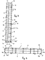
- the wire mesh basket has a front and a back 1, 2, which are interconnected by narrow end faces 3, 4 and a correspondingly narrow bottom 5.
- the back 2 which faces in the installed position of the wire rack a cover to be covered facade 6 ( Fig. 5 ), has longitudinally extending longitudinal wires 7, which are interconnected by horizontal transverse wires 8.
- the wires 7, 8 define rectangular grid openings 9, which are provided so that the longitudinal sides of these grid openings extend horizontally.
- the back 2 has at the two longitudinal edges in each case a longitudinal wire 7 '.
- the upper ends of the longitudinal wires 7, 7 ' are connected by an upper horizontal transverse wire 8. With their lower ends, the longitudinal wires 7, 7 'protrude downwards over the lower transverse wire 8.
- the front 1, the end faces 3, 4, which form the narrow sides of the wire rack basket, and the bottom 5 are formed by a further wire grid, which consists of vertically extending longitudinal wires 10 and these connecting, horizontally extending transverse wires 11.
- the upper ends of the longitudinal wires 10 are interconnected by an upper cross wire 11, while the lower ends of the longitudinal wires 10 project beyond the lower cross wire 11.
- the ends 11 a, 11 b ( Fig. 4 ) of the horizontal transverse wires 11 bent at right angles. At their free ends, the transverse wire ends 11 a, 11 b are bent in a hook shape, so that hooks 11 a ', 11 b' are formed. They surround the end-side longitudinal wires 7 'of the back 2.
- the horizontal transverse wire ends 11 a, 11 b are connected by a longitudinal wire 12 together. It is provided so as not to project beyond the upper and lower cross wire ends 11a, 11b ( Fig. 3 ).
- the longitudinal wire 12 stiffens the narrow sides 3, 4, so that they have sufficient strength and rigidity.
- the longitudinal wires 10 and the transverse wires 11 define rectangular grid openings 13 (FIG. Fig. 1 ), whose longitudinal sides extend horizontally.
- the grid openings 13 are advantageously the same size as the grid openings 9 of the front side 1.
- the longitudinal wire 12 in the narrow sides 3, 4 is arranged off-center in the embodiment, whereby the narrow sides have two different sized grid openings 14, 15 ( Fig. 3 ).
- the grid opening 14 has a square outline, while the grid opening 15 has a rectangular outline, this grid opening being provided so that the longitudinal side is horizontal.
- the grid opening 15 connects to the back 2 and the grid opening 14 to the front side 1 of the wire rack.
- the rectangular grid opening 15 can also connect to the front side 1 and the square grid opening 14 to the rear side 2. Furthermore, it is possible that the longitudinal wire 12 is also provided in half the width of the narrow sides 3, 4.
- the longitudinal wires 10 project with their lower ends over the lower transverse wire 11 before ( Fig. 3 ).
- This projecting end 10a of the longitudinal wires 10 is bent at right angles and formed at the free end to a hook 10a '.
- the hooks 10a engage around the lower cross wire 8 of the back 2 ( Fig. 3 ).
- the hooks 11a 'of the transverse wires 11 embrace the end-side longitudinal wires 7' of the back 2 from the outside, so that the ends of these hooks are directed inwardly into the wire mesh cage. The hook ends thus do not lead to injuries when handling the wire rack.
- the bent longitudinal wire ends 10a are interconnected by transverse wires 16 which extend horizontally and whose free ends 16a, 16b are bent at right angles upwards.
- the free transverse wire ends 16a, 16b are equal to the narrow sides 3, 4 of the wire rack.
- the transverse wires 16 are provided so that one transverse wire 16 lies approximately half the width of the narrow side 3, 4 and the other transverse wire 16 is close to the front side 1 of the wire mesh basket.
- the bent longitudinal wire ends 10a and the transverse wires 16 form the bottom 5 of the wire mesh basket and define grid openings 17 which have a rectangular outline. Their long sides extend horizontally.
- the grid openings 17 are due to the arrangement of the transverse wires 16 of different sizes.
- the wire mesh basket is formed in the manner described only by two wire mesh, which are connected to each other via the hooks 10a ', 11a', 11 b 'of the longitudinal and transverse wires 10, 11 of the front and the narrow sides 3, 4 forming wire grid.
- the wire mesh basket can be made simple and inexpensive.
- the front 1 and the back 2 are connected by spacers 18 which are distributed over the height and length of the wire rack basket.
- the spacers 18 are formed by wires whose two ends 18a, 18b are formed into hooks with which the spacers 18 are suspended in transverse wires 8, 11 in the front 1 and in the back 2. So that the spacers 18 can not slip along the transverse wires, one hook 18a is suspended at the point of intersection of the corresponding longitudinal wire 10 and transverse wire 11.
- the spacers 18 prevent the front 1 and the back 2 bulge outwards when the wire mesh basket is filled.
- the wire mesh basket Since the wire mesh basket has only a very small depth, it also has only a small receiving volume, so that the filled wire mesh basket has only low weight. It is only about 20 to 25 kg. Therefore, the wire mesh basket filled with stones can be transported and mounted by the user without lifting equipment. Therefore, the wire mesh basket is ideal for do-it-yourselfers who can mount the wall panel themselves.
- the wires of the wire mesh basket are advantageously made of corrosion-resistant material, in particular stainless steel, so that the wire mesh basket can be easily used outdoors without corrosion problems are to be feared.
- a relatively thin wire can be used, for example, has only a wire diameter of 2.5 mm. Because of this small wire diameter, the wireframe basket requires less wire material, so the cost of such a wireframe basket with stainless steel wires is almost the same as a wire mesh basket whose bars are made of galvanized steel.
- the horizontal orientation of the grid openings 13 in the front 1 has an effect on the appearance of the wire rack when viewed from a very small angle from the side.
- the horizontal orientation of the grid openings means that despite this flat angle, the stones in the wire mesh basket can be seen. If the rectangular grid openings are aligned vertically, then only the wires in the front 1 are visible in this lateral flat viewing angle, but not the stones located in the wire mesh basket.
- the wire mesh cage is designed so that the horizontal transverse wires are on the outside, while the vertically extending L'Harsdrähte are attached to the inside of the transverse wires in the crossing points. This arrangement of the grid wires helps, in conjunction with the horizontal alignment of the grid openings at a flat view, the stones in the wire mesh basket are clearly visible.
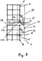
- the wire mesh baskets are designed so that in each case two superimposed wire mesh baskets can be fastened to a common retaining rail 19 ( Fig. 5 ).
- the retaining rail 19 has a flat fastening part 20 which rests flat in the installed position on the facade 6 of the wall to be clad. From the upper and lower edge of the fastening part 20 is in each case at least one suspension part 21, 22 from. Both suspension parts are advantageously formed integrally with the fastening part 20 and extend parallel to each other obliquely upwards.
- the hooking parts 21, 22 may extend over the length of the fastening part 20. But it is also possible that the fastening part 20 is longer than the hooking parts 21, 22nd
- the retaining rail 19 may extend over more than the width of the wire mesh basket, for example, over two or more adjacent to each other on the facade 6 to be arranged wire mesh baskets.
- the wire mesh baskets along the support rail 19 can optimally bring into the required installation position.
- the retaining rails 19 are fastened by one or more fastening screws 23 on the facade 6.
- corresponding hooks 24 are provided on the back 2. They are the same design and each bent from a wire.
- the suspension hook 24 is based on the Fig. 2 and 5 described in more detail.
- the suspension hook 24 ( Fig. 2 . 5 ) has a Einitatiteil 25, which is U-shaped and in the mounted position, the upper Ein fatigueteil 21 of the retaining rail 19 overlaps.
- the U-shaped suspension part 25 is at an acute angle to a fastening part 26, which has two legs 26a lying parallel to one another in a common plane.
- the lower ends of the legs 26a are hook-shaped and embrace one of the transverse wires 8 of the back 2 from the outside.
- one leg 27a of the hook 27 is angled outwardly at an obtuse angle relative to the fastening part 26, so that the hook 27 can embrace the corresponding transverse wire 8 from the outside.
- the other leg 27b protrudes into the wire mesh basket, so that there is no risk of injury to the user during assembly.
- the hooks 24 is disposed on the back 2, that the hooking part 25 and the legs 27a of the hook portion 27 protrude beyond the back 2.
- Fig. 2 shows, the legs of the U-shaped Ein vonmaschines 25, the fastening part 26 and the hook portion 27 are each in a common plane.
- the fastening part 26 is located at mounted wire mesh basket approximately at the level of the longitudinal wires 7 of the back. 2
- the hooks 24 are provided near the top and near the bottom 5 of the wire rack. Depending on the width of the wire rack, two or more hooks 24 are provided near the top and bottom of the wire rack.
- the hooks 24 are advantageously fixedly connected to the corresponding grid wires; but they can also be hung loosely in the back 2.
- the hooks 24 are provided on the wire mesh baskets that two superimposed wire mesh baskets can be hooked into the common support rail 19 ( Fig. 5 ).
- the lower Ein fatiguemaschine 25 of upper wire rack basket are under the weight on the suspension part 21 of the support rail 19.
- the Ein fatigueteil 25 serves as Wegziehsperre for the wire rack basket, which ensures that the wire mesh basket comes with its lower portion with appropriate lateral load is not disengaged from the hooking part 21 of the support rail 19.
- the Ein skilleder 22 of the support rails 19 serve as load-receiving parts that receive the weight of the wire rack basket.
- the hook parts 27 embrace from outside the respective transverse wire 8 of the back 2, whereby a secure attachment of the wire mesh baskets to the support rails 19 is ensured.
- the retaining rail 19 is provided in the manner described both with the Wegziehsperre in the form of Ein rehabilitationmaschines 21 and with the load receiving part in the form of Ein fatigueers 22. Since this only a single component is provided, not only results in a simple and inexpensive production of the retaining rail 19, but also a simple installation that can be made by do-it-yourselfers.
- the distance between the Ein von too many 21, 22 is chosen so that the respective lower wire mesh basket can not be unhooked when the upper wire mesh basket is mounted.
- the retaining rail 19 thereby serves as a safeguard against unhooking the wire mesh baskets.
- the wall cladding formed from the wire mesh baskets has horizontally extending joints 28 (FIG. Fig. 5 ), which are formed between stacked wire mesh baskets.
- the width of these joints 28 is determined by the support rail 19 and can not be changed by the user.
- This horizontally extending joint 28 can be optimally designed with the retaining rail 19 with respect to the joint image of the wall cladding. Since the width of the joint 28 during assembly of the wall panel can not be changed, the optimum joint width between stacked wire mesh baskets is always maintained. That way it will be reliable and very easy to get a uniform joint pattern in the wall paneling.
- the position of the hooks 24 is chosen so that the retaining rail 19 may be formed as narrow as possible. This has advantages with regard to the rigidity of the retaining rail 19. If the fastening part 20 of the retaining rail 19 wide, then the wall paneling is unstable and sensitive to vibration. Thus, in such a configuration, the retaining rail 19 bulge forward under the weight of the wire mesh baskets. Also, vibrations can occur due to wind suction and wind pressure.
- the retaining rail 19 can not bulge forward under the weight of the wire mesh baskets. Also caused by wind suction and wind pressure possibly triggered vibrations of the retaining rail 19 and the hinged wire mesh baskets reliably.
- the wire mesh baskets can be placed on the support rail 19 that the Ein vonmaschine 21, 22 of the support rails 19 come with their free ends to the grid wires of the back 2 to the plant ( Fig. 5 ).
- a precise positioning of the wire mesh baskets relative to one another and to the facade 8 is achieved in a simple manner.
- the fastening screws 23 are provided in the upper region of the fastening part 20 of the retaining rail 19. This prevents that the fastening part 23 is bent away from the facade 6 under the load of the hinged wire mesh baskets.
- the fastening wrenches 23 are preferably provided with only a small distance from the transition of the fastening part 20 into the upper suspension part 21.
- wire mesh baskets have a low weight in the filled state, which is less than about 25 kg, for the support rail 19, a relatively thin steel part can be used.
- the obliquely upwardly bent-in suspension parts 21, 29 can safely receive the load without being bent down under the load relative to the fastening part 20.
- the filled wire mesh baskets Due to the low weight of the filled wire mesh baskets can be used for their attachment to the facade 6 normal brickwork. With an exemplary width and height of 50 cm, four wire mesh baskets per square meter can be installed.
- the wire mesh baskets are characterized by their very compact design and their low weight in the filled state. This makes it possible that even individuals can mount such wire mesh baskets as wall panels themselves. A hoist is not required for installation. Due to the low weight, the filled wire mesh baskets can be manually moved and mounted on the support rails 19. The support rails themselves can be easily attached to the masonry with the mounting screws 23. Due to the low weight is no special masonry, such as a concrete wall, required, so that the wall paneling can be attached to standard masonry.
- the lightweight design results in a weight per unit area of less than 100 kg / m 2 , while previously standard baskets have a basis weight of up to 240 kg / m 2 .
- Baskets with a basis weight of 210 to 240 kg / m 2 are only suitable for suspension on concrete walls.
- the low basis weight also allows the use of significantly thicker insulation, especially heat insulation, but also insulation for reflection sound.
Landscapes
- Engineering & Computer Science (AREA)
- Architecture (AREA)
- Civil Engineering (AREA)
- Structural Engineering (AREA)
- Pit Excavations, Shoring, Fill Or Stabilisation Of Slopes (AREA)
Description
Die Erfindung betrifft eine Wandverkleidung mit Drahtgitterkörben nach dem Oberbegriff des Anspruches 1. Eine solche Wandverkleidung ist aus
Es ist bekannt, Wandverkleidungen mit Drahtgitterkörben zu bilden, die in an der zu verkleidenden Wand befestigten Halteschienen neben- und übereinander eingehängt werden. Die Drahtgitterkörbe werden mit Material gefüllt, in der Regel mit Steinen. Die befüllten Drahtgitterkörbe haben ein erhebliches Gewicht, das größer als 100 kg ist. Darum ist zur Montage der Wandverkleidung ein Hebezeug erforderlich. Deshalb können solche Wandverkleidungen nur von Fachleuten mit entsprechenden Geräten montiert werden. Die Montage der Wandverkleidung aus solchen Drahtgitterkörben ist darum auch verhältnismäßig teuer.It is known to form wall cladding with wire mesh baskets, which are hung side by side and one above the other in holding rails fastened to the wall to be clad. The wire mesh baskets are filled with material, usually with stones. The filled wire mesh baskets have a significant weight, which is greater than 100 kg. Therefore, a hoist is required to install the wall cladding. Therefore, such wall coverings can be mounted only by professionals with appropriate equipment. The installation of the wall covering of such wire mesh baskets is therefore relatively expensive.
Damit die Drahtgitterkörbe genau positioniert werden können, sind sie an ihrer Rückseite mit Aufhängeteilen versehen, die in die Halteschienen eingehängt werden. Außerdem befinden sich an der Rückseite der Drahtgitterkörbe Abstandhalter, die dafür sorgen, dass die eingehängten Drahtgitterkörbe nicht in Schräglage relativ zur zu verkleidenden Wand gelangen. Es ist somit ein erheblicher technischer Aufwand erforderlich, um die Wandverkleidung zu montieren.In order to be able to position the wire mesh baskets precisely, they are provided with suspension parts on their rear side, which are suspended in the support rails. In addition, located at the back of the wire mesh baskets spacers, which ensure that the hinged wire mesh baskets do not reach in an inclined position relative to the wall to be covered. It is thus a considerable technical effort required to mount the wall covering.
Der Erfindung liegt die Aufgabe zugrunde, die gattungsgemäße Wandverkleidung und den gattungsgemäßen Drahtgitterkorb so auszubilden, dass eine problemlose Handhabung des Drahtgitterkorbes möglich ist, insbesondere bei der Herstellung von Wandverkleidungen.The invention has the object of providing the generic wall paneling and the generic wire mesh basket in such a way that easy handling of the wire rack is possible, especially in the production of wall coverings.
Diese Aufgabe wird bei der gattungsgemäßen Wandverkleidung erfindungsgemäß mit den kennzeichnenden Merkmalen des Anspruches 1 und beim gattungsgemäßen Drahtgitterkorb erfindungsgemäß mit den kennzeichnenden Merkmalen des Anspruches 14 gelöst.This object is achieved in the generic wall paneling according to the invention with the characterizing features of
Bei der erfindungsgemäßen Wandverkleidung werden Halteschienen eingesetzt, die so ausgebildet sind, dass sie gleichzeitig als Wegziehsperre und zur Lastaufnahme dienen. Darum sind für diese beiden unterschiedlichen Funktionen keine getrennten Bauteile erforderlich. Mit der Befestigung der Halteschiene an der Wand sind die Wegziehsperre und der Lastaufnahmeteil bereits positionsgenau montiert, so dass nur noch die Drahtgitterkörbe mit ihren Einhängeelementen eingehängt werden müssen. Die Montage einer Wandverkleidung ist darum sehr einfach möglich. Bei Anordnung von übereinanderliegenden Drahtgitterkörben dient die Halteschiene dem jeweils oberen Drahtgitterkorb als Wegziehsperre und als Abstandshalterung und dem jeweils darunterliegenden Drahtgitterkorb zur Lastaufnahme. Die Wegziehsperre wird durch einen abgewinkelten oberen Rand eines Befestigungsteiles der Halteschiene gebildet. Mit dem Befestigungsteil wird die Halteschiene an der Wand befestigt. Die Halteschiene kann in vorteilhafter Weise durch eine flache Schiene gebildet sein, deren oberer Rand zur Bildung der Wegziehsperre abgewinkelt wird. Der Lastaufnahmeteil wird durch den unteren abgewinkelten Rand des Befestigungsteils der Halteschiene gebildet.In the wall cladding according to the invention retaining rails are used, which are designed so that they also serve as Wegziehsperre and for receiving loads. Therefore, no separate components are required for these two different functions. With the attachment of the retaining rail on the wall Wegziehsperre and the load receiving part are already mounted accurately positioned so that only the wire mesh baskets must be hung with their suspension elements. The installation of a wall cladding is therefore very easy. In the arrangement of superimposed wire mesh baskets, the retaining rail serves the respective upper wire mesh basket as a pull-out barrier and as a spacer and the respective underlying wire mesh cage for receiving loads. The Wegziehsperre is formed by an angled upper edge of a fastening part of the retaining rail. With the fastening part, the retaining rail is attached to the wall. The retaining rail can be formed in an advantageous manner by a flat rail, the upper edge is angled to form the Wegziehsperperre. The load receiving part is formed by the lower angled edge of the fastening part of the retaining rail.
Die Halteschiene kann somit sehr einfach aus einem flachen Blechteil gebildet werden, deren oberer und unterer Rand lediglich abgewinkelt werden, was in einfacher Weise möglich ist. Die Wegziehsperre und der Lastaufnahmeteil liegen etwa parallel zueinander und erstrecken sich vom Befestigungsteil aus schräg aufwärts.The support rail can thus be easily formed from a flat sheet metal part whose upper and lower edges are merely angled, which is possible in a simple manner. The Wegziehsperre and the load-receiving part are approximately parallel to each other and extend from the fastening part of obliquely upward.
Wenn der Befestigungsteil der Halteschiene in seiner oberen Hälfte, vorzugsweise im oberen Drittel, wenigstens eine Durchtrittsöffnung für eine Befestigungsschraube aufweist, dann kann die Halteschiene so montiert werden, dass der an die Wegziehsperre anschließende Bereich des Befestigungsteiles unter der Last der eingehängten Drahtgitterkörbe nicht von der Wand weg gebogen wird.If the fastening part of the retaining rail in its upper half, preferably in the upper third, at least one passage opening for a fastening screw, then the retaining rail can be mounted so that the adjoining the Wegziehsperre area of the fastening part under the load of the hinged wire mesh baskets not from the wall is bent away.
Die zum Einhängen der Drahtgitterkörbe eingesetzten Einhängeelemente sind hakenförmig ausgebildet und aus einem gebogenen Gitterdraht hergestellt. Aus ihm lässt sich das Einhängeelement einfach und kostengünstig fertigen.The hooking elements used for hanging the wire mesh baskets are hook-shaped and made of a bent grid wire. From him, the hanging element can be easily and inexpensively finished.
Das Einhängeelement hat in vorteilhafter Weise am oberen Ende einen über den Drahtgitterkorb in Richtung auf die Halteschiene vorstehenden Einhängeteil. Dadurch lässt sich der Drahtgitterkorb einfach in die Halteschiene einhängen.The suspension element has advantageously at the upper end over the wire mesh cage in the direction of the retaining rail projecting hanger. As a result, the wire mesh basket can be easily hooked into the retaining rail.
Eine zuverlässige Sicherung des Einhängeelementes am Drahtgitterkorb wird erreicht, wenn das Einhängeelement am unteren Ende einen Hakenteil aufweist, der einen Querdraht des Drahtgitterkorbes umgreift. Unter der Last des Drahtgitterkorbes liegt der entsprechende Querdraht im Hakenteil des Einhängeelementes, so dass das Einhängeelement unverlierbar am Drahtgitterkorb gehalten wird.Reliable securing of the suspension element on the wire mesh cage is achieved when the suspension element has a hook part at the lower end which engages around a transverse wire of the wire mesh cage. Under the load of the wire rack basket, the corresponding transverse wire is in the hook part of the hooking element, so that the hooking element is held captive on the wire mesh basket.
Bevorzugt besteht der Gitterdraht des Drahtgitterkorbes aus Edelstahl, so dass die Wandverkleidung, die sich in der Regel im Freien befindet, eine lange Lebensdauer hat.Preferably, the wire mesh of the wire mesh cage is made of stainless steel, so that the wall covering, which is usually outdoors, has a long life.
Vorteilhaft hat der Gitterdraht nur einen Durchmesser von ≤ etwa 2,5 mm. Wenn der Gitterdraht in bevorzugter Weise aus Edelstahl besteht, bedeutet die Verwendung eines geringen Drahtdurchmessers, dass weniger Material für den Gitterdraht benötigt wird, so dass der Drahtgitterkorb trotz Verwendung von Edelstahl-Gitterdrähten preislich nicht wesentlich höher liegt als herkömmliche Drahtgitterkörbe aus verzinkten Gitterdrähten.Advantageously, the grid wire only has a diameter of ≤ about 2.5 mm. When the grid wire is preferably stainless steel, the use of a small wire diameter means that less material is needed for the grid wire so that the wire mesh basket, despite the use of stainless steel grid wires, is not significantly higher in price than conventional wire mesh baskets made of galvanized grid wires.
Damit eine einfache Handhabung des Drahtgitterkorbes möglich ist, hat er mit Befüllung ein Gewicht von nur ≤ etwa 25 kg. Solche Drahtgitterkörbe können vom Anwender ohne Einsatz von Hebezeug gehandhabt werden, so dass auch Privatanwender problemlos Wandverkleidungen mit solchen Drahtgitterkörben errichten können.To allow easy handling of the wire rack, it has a weight of only ≤ about 25 kg with filling. Such wire mesh baskets can be handled by the user without the use of lifting equipment, so that even private users can easily erect wall coverings with such wire mesh baskets.
Besonders vorteilhaft ist es, wenn zumindest die Sichtseite, d.h. die von der zu verkleidenden Wand abgewandte Außenseite des Drahtgitterkorbes, rechteckige Öffnungen aufweist, deren Längsseiten sich horizontal erstrecken. Es hat sich gezeigt, dass bei einer solchen Orientierung der rechteckigen Gitteröffnungen die Befüllung der Drahtgitterkörbe auch dann deutlich sichtbar ist, wenn der Betrachter von der Seite unter einem sehr schrägen Winkel auf die Wandverkleidung schaut. Bei rechteckigen Gitteröffnungen, die vertikal angeordnet sind, sind in einem solchen Falle im Wesentlichen nur die Gitterdrähte zu erkennen, nicht aber die Befüllung der Drahtgitterkörbe.It is particularly advantageous if at least the visible side, i. the outside facing away from the wall to be covered wall of the wire rack, rectangular openings, the longitudinal sides extend horizontally. It has been found that in such an orientation of the rectangular grid openings, the filling of the wire mesh baskets is clearly visible even when the viewer looks from the side at a very oblique angle to the wall covering. In the case of rectangular grid openings, which are arranged vertically, essentially only the grid wires can be seen in such a case, but not the filling of the wire cage baskets.
Vorteilhaft ist der Abstand zwischen der Wegziehsperre und dem Lastaufnahmeteil der Halteschiene so gewählt, dass der jeweils untere Drahtgitterkorb nicht ausgehängt werden kann, wenn der jeweils obere Drahtgitterkorb eingehängt ist. Die Halteschiene erfüllt somit eine weitere Funktion, nämlich eine Sicherung gegen Aushängen der Drahtgitterkörbe in montiertem Zustand. Wenn die Wegziehsperre und der Lastaufnahmeteil an zwei getrennten Halteschienen vorgesehen wären, dann wäre nicht sichergestellt, dass die Aushängesicherung bei der Montage der Wandverkleidung auf jeden Fall gewährleistet ist. Es würde vom Anwender abhängen, wie sorgfältig er in diesem Falle die beiden Halteschienen mit dem notwendigen Abstand an der Fassade montiert. Infolge der erfindungsgemäßen Ausbildung werden diese Probleme verhindert, weil mit der Befestigung der Halteschiene an der Fassade der Abstand zwischen der Wegziehsperre und dem Lastaufnahmeteil vorgegeben ist und vom Anwender nicht verändert werden kann.Advantageously, the distance between the Wegziehsperre and the load receiving part of the retaining rail is chosen so that the respective lower wire mesh basket can not be unmounted when the upper wire mesh basket is mounted. The retaining rail thus fulfills a further function, namely a safeguard against unhooking the wire mesh baskets in the assembled state. If the Wegziehsperre and the load receiving part would be provided on two separate support rails, then it would not be ensured that the safety catch is guaranteed in the assembly of the wall panel in any case. It would depend on the user how careful he is in this case, the two support rails mounted with the necessary distance to the facade. As a result of the inventive training these problems are prevented because with the attachment of the retaining rail on the facade of the distance between the Wegziehsperre and the load-receiving part is predetermined and can not be changed by the user.
Der erfindungsgemäße Drahtgitterkorb zeichnet sich vor allen Dingen durch seine lange Einsatzdauer und sein geringes Gewicht aus. Der Drahtgitterkorb kann von Privatanwendern sehr einfach gehandhabt werden, da sein Gewicht mit Befüllung ≤ etwa 25 kg ist. Erreicht wird dies durch eine entsprechende kompakte Gestaltung des Drahtgitterkorbes, der beispielsweise eine Breite und eine Höhe von 50 cm sowie eine Tiefe von beispielsweise nur etwa 7 cm hat. Die Verwendung von Edelstahl für die Gitterdrähte stellt eine lange Einsatzdauer sicher, insbesondere beim Außeneinsatz des Drahtgitterkorbes. Da die Längsseiten der Gitteröffnungen zumindest in der Vorder- und damit der Sichtseite des Drahtgitterkorbes horizontal verlaufen, kann die Befüllung des Drahtgitterkorbes auch bei sehr schräger Seitenansicht des Drahtgitterkorbes erkannt werden.The wire mesh cage according to the invention is distinguished above all by its long service life and its low weight. The wire mesh basket can be handled very easily by home users, since its weight with filling is ≤ about 25 kg. This is achieved by a corresponding compact design of the wire rack basket, for example, has a width and a height of 50 cm and a depth of, for example, only about 7 cm. The use of stainless steel for the grid wires ensures a long service life, especially in the outdoor use of the wire rack basket. Since the longitudinal sides of the grid openings extend horizontally at least in the front and thus the visible side of the wire rack, the filling of the wire mesh basket can be detected even with very oblique side view of the wire rack.
Bei einer optimalen Ausführungsform liegen die Längsdrähte an der der Innenseite des Drahtgitterkorbes zugewandten Seite der Querdrähte.In an optimal embodiment, the longitudinal wires are located on the side of the transverse wires facing the inside of the wire mesh basket.
Eine besonders einfache Gestaltung und Herstellung ergibt sich, wenn der Drahtgitterkorb nur durch zwei Drahtgitter gebildet wird.A particularly simple design and manufacture results when the wire mesh cage is formed only by two wire mesh.
Hierbei bildet das eine Drahtgitter in bevorzugter Weise die Rückseite des Drahtgitterkorbes.In this case, the one wire grid preferably forms the rear side of the wire mesh basket.
Das andere Drahtgitter wird dann so geformt, dass es die Vorderseite, die Seitenwände und den Boden des Drahtgitterkorbes bildet.The other wire grid is then formed to form the front, side and bottom of the wire rack.
Der Anmeldungsgegenstand ergibt sich nicht nur aus dem Gegenstand der einzelnen Patentansprüche, sondern auch durch alle in den Zeichnungen und der Beschreibung offenbarten Angaben und Merkmale. Sie werden, auch wenn sie nicht Gegenstand der Ansprüche sind, als erfindungswesentlich beansprucht, soweit sie einzeln oder in Kombination gegenüber dem Stand der Technik neu sind.The subject of the application results not only from the subject matter of the individual claims, but also by all in the drawings and the description disclosed disclosures and features. They are, even if they are not the subject of the claims, claimed as essential to the invention, as far as they are new individually or in combination over the prior art.
Weitere Merkmale der Erfindung ergeben sich aus den weiteren Ansprüchen, der Beschreibung und den Zeichnungen.Further features of the invention will become apparent from the other claims, the description and the drawings.
Die Erfindung wird anhand eines in den Zeichnungen dargestellten Ausführungsbeispieles näher erläutert. Es zeigen
- Fig. 1
- in perspektivischer Darstellung einen erfindungsgemäßen Drahtgitterkorb,
- Fig. 2
- eine Rückansicht des Drahtgitterkorbes gemäß
Fig. 1 , - Fig. 3
- in vergrößerter Darstellung eine Seitenansicht des erfindungsgemäßen Drahtgitterkorbes,
- Fig. 4
- eine Draufsicht auf den erfindungsgemäßen Drahtgitterkorb,
- Fig. 5
- in vergrößerter Darstellung Teile von übereinander angeordneten erfindungsgemäßen Drahtgitterkörben, die in eine gemeinsame Einhängeschiene eingehängt und Teil einer erfindungsgemäßen Wandverkleidung sind.
- Fig. 1
- in a perspective view of a wire mesh basket according to the invention,
- Fig. 2
- a rear view of the wire mesh basket according to
Fig. 1 . - Fig. 3
- in an enlarged view a side view of the wire mesh basket according to the invention,
- Fig. 4
- a top view of the wire mesh basket according to the invention,
- Fig. 5
- in an enlarged scale parts of superimposed wire mesh baskets according to the invention, which are mounted in a common Einhängeschiene and part of a wall panel according to the invention.
Die Wandverkleidung wird durch Drahtgitterkörbe gebildet, die sich dadurch auszeichnen, dass sie sehr schmal ausgebildet sind. So hat beispielhaft der Drahtgitterkorb eine Breite von 50 cm, eine Höhe von 50 cm und eine Tiefe von nur 7 cm. Diese Maßangaben sind nicht beschränkend zu verstehen und können von den angegebenen Werten abweichen. Allerdings ist die Tiefe des Drahtgitterkorbes wesentlich geringer als bei herkömmlichen Drahtgitterkörben, die für Wandverkleidungen eingesetzt werden.The wall cladding is formed by wire mesh baskets, which are characterized in that they are very narrow. For example, the wire mesh basket has a width of 50 cm, a height of 50 cm and a depth of only 7 cm. These dimensions are not meant to be limiting and may deviate from the stated values. However, the depth of the wire mesh basket is much lower than in conventional wire mesh baskets used for wall coverings.
Der Drahtgitterkorb hat eine Vorder- und eine Rückseite 1, 2, die durch schmale Stirnseiten 3, 4 und einen entsprechend schmalen Boden 5 miteinander verbunden sind. Die Rückseite 2, die in der Einbaulage des Drahtgitterkorbes einer abzudeckenden Fassade 6 zugewandt ist (
Die Rückseite 2 weist an den beiden Längsrändern jeweils einen Längsdraht 7' auf. Die oberen Enden der Längsdrähte 7, 7' sind durch einen oberen horizontalen Querdraht 8 verbunden. Mit ihren unteren Enden ragen die Längsdrähte 7, 7' nach unten über den unteren Querdraht 8.The
Die Vorderseite 1, die Stirnseiten 3, 4, welche die Schmalseiten des Drahtgitterkorbes bilden, und der Boden 5 werden durch ein weiteres Drahtgitter gebildet, das aus in Höhenrichtung verlaufenden Längsdrähten 10 und diese verbindenden, horizontal verlaufenden Querdrähten 11 besteht. Die oberen Enden der Längsdrähte 10 sind durch einen oberen Querdraht 11 miteinander verbunden, während die unteren Enden der Längsdrähte 10 über den unteren Querdraht 11 vorstehen.The
Zur Bildung der Stirn/Schmalseiten 3, 4 des Drahtgitterkorbes sind die Enden 11 a, 11 b (
Die Längsdrähte 10 und die Querdrähte 11 begrenzen rechteckige Gitteröffnungen 13 (
Der Längsdraht 12 in den Schmalseiten 3, 4 ist im Ausführungsbeispiel außermittig angeordnet, wodurch die Schmalseiten zwei unterschiedlich große Gitteröffnungen 14, 15 aufweisen (
Je nach Lage des Längsdrahtes 12 in den Schmalseiten 3, 4 kann die rechteckige Gitteröffnung 15 auch an die Vorderseite 1 und die quadratische Gitteröffnung 14 an die Rückseite 2 anschließen. Ferner ist es möglich, dass der Längsdraht 12 auch in halber Breite der Schmalseiten 3, 4 vorgesehen ist.Depending on the position of the
Die Längsdrähte 10 ragen mit ihren unteren Enden über den unteren Querdraht 11 vor (
Die abgebogenen Längsdrahtenden 10a sind durch Querdrähte 16 miteinander verbunden, die horizontal verlaufen und deren freie Enden 16a, 16b rechtwinklig aufwärts gebogen sind. Die freien Querdrahtenden 16a, 16b liegen in Höhe der Schmalseiten 3, 4 des Drahtgitterkorbes. Wie aus den
Die abgebogenen Längsdrahtenden 10a sowie die Querdrähte 16 bilden den Boden 5 des Drahtgitterkorbes und begrenzen Gitteröffnungen 17, die rechteckigen Umriss haben. Ihre Längsseiten erstrecken sich horizontal. Die Gitteröffnungen 17 sind wegen der Anordnung der Querdrähte 16 unterschiedlich groß.The bent longitudinal wire ends 10a and the
Der Drahtgitterkorb wird in der beschriebenen Weise lediglich durch zwei Drahtgitter gebildet, die über die Haken 10a', 11a', 11 b' der Längs- und der Querdrähte 10, 11 des die Vorderseite und die Schmalseiten 3, 4 bildenden Drahtgitters miteinander verbunden sind. Der Drahtgitterkorb kann dadurch einfach und kostengünstig hergestellt werden.The wire mesh basket is formed in the manner described only by two wire mesh, which are connected to each other via the
Die Vorderseite 1 und die Rückseite 2 sind durch Abstandhalter 18 miteinander verbunden, die über die Höhe und Länge des Drahtgitterkorbes verteilt angeordnet sind. Die Abstandhalter 18 werden durch Drähte gebildet, deren beide Enden 18a, 18b zu Haken geformt sind, mit denen die Abstandhalter 18 in Querdrähte 8, 11 in der Vorderseite 1 und in der Rückseite 2 eingehängt sind. Damit die Abstandhalter 18 nicht längs der Querdrähte verrutschen können, ist der eine Haken 18a im Kreuzungspunkt des entsprechenden Längsdrahtes 10 und Querdrahtes 11 eingehängt. Die Abstandhalter 18 verhindern, dass die Vorderseite 1 und die Rückseite 2 bei gefülltem Drahtgitterkorb nach außen ausbauchen.The
Da der Drahtgitterkorb nur eine sehr geringe Tiefe hat, hat er auch nur ein geringes Aufnahmevolumen, so dass der gefüllte Drahtgitterkorb nur geringes Gewicht hat. Es liegt bei nur etwa 20 bis 25 kg. Darum kann der mit Steinen gefüllte Drahtgitterkorb ohne Hebezeug vom Anwender transportiert und montiert werden. Darum eignet sich der Drahtgitterkorb hervorragend für Heimwerker, die dadurch die Wandverkleidung selbst montieren können.Since the wire mesh basket has only a very small depth, it also has only a small receiving volume, so that the filled wire mesh basket has only low weight. It is only about 20 to 25 kg. Therefore, the wire mesh basket filled with stones can be transported and mounted by the user without lifting equipment. Therefore, the wire mesh basket is ideal for do-it-yourselfers who can mount the wall panel themselves.
Die Drähte des Drahtgitterkorbes bestehen vorteilhaft aus korrosionsbeständigem Material, insbesondere aus Edelstahl, so dass der Drahtgitterkorb problemlos im Freien eingesetzt werden kann, ohne dass Korrosionsprobleme zu befürchten sind. Bei Einsatz von Edelstahl für die Drähte des Drahtgitterkorbes kann ein verhältnismäßig dünner Draht eingesetzt werden, der beispielsweise nur einen Drahtdurchmesser von 2,5 mm aufweist. Aufgrund dieses geringen Drahtdurchmessers wird für den Drahtgitterkorb weniger Drahtmaterial benötigt, so dass die Kosten für einen solchen Drahtgitterkorb mit Drähten aus Edelstahl nahezu gleich sind wie für einen Drahtgitterkorb, dessen Gitterstäbe aus verzinktem Stahl bestehen.The wires of the wire mesh basket are advantageously made of corrosion-resistant material, in particular stainless steel, so that the wire mesh basket can be easily used outdoors without corrosion problems are to be feared. When using stainless steel for the wires of the wire rack, a relatively thin wire can be used, for example, has only a wire diameter of 2.5 mm. Because of this small wire diameter, the wireframe basket requires less wire material, so the cost of such a wireframe basket with stainless steel wires is almost the same as a wire mesh basket whose bars are made of galvanized steel.
Die horizontale Ausrichtung der Gitteröffnungen 13 in der Vorderseite 1 hat Auswirkungen auf das Erscheinungsbild des Drahtgitterkorbes, wenn er unter einem sehr kleinen Winkel von der Seite aus betrachtet wird. Die horizontale Ausrichtung der Gitteröffnungen führt dazu, dass trotz dieses flachen Blickwinkels die im Drahtgitterkorb befindlichen Steine zu sehen sind. Wenn die rechteckigen Gitteröffnungen vertikal ausgerichtet sind, dann sind bei diesem seitlichen flachen Blickwinkel nur noch die Drähte in der Vorderseite 1 sichtbar, nicht jedoch die im Drahtgitterkorb befindlichen Steine.The horizontal orientation of the
Der Drahtgitterkorb ist so gestaltet, dass sich die horizontalen Querdrähte an der Außenseite befinden, während die in vertikaler Richtung verlaufenden L'ängsdrähte an der Innenseite der Querdrähte in den Kreuzungspunkten befestigt sind. Diese Anordnung der Gitterdrähte trägt dazu bei, dass in Verbindung mit der horizontalen Ausrichtung der Gitteröffnungen bei einem flachen Blickwinkel die im Drahtgitterkorb befindlichen Steine deutlich sichtbar sind.The wire mesh cage is designed so that the horizontal transverse wires are on the outside, while the vertically extending L'ängsdrähte are attached to the inside of the transverse wires in the crossing points. This arrangement of the grid wires helps, in conjunction with the horizontal alignment of the grid openings at a flat view, the stones in the wire mesh basket are clearly visible.
Die Drahtgitterkörbe sind so ausgebildet, dass jeweils zwei übereinander liegende Drahtgitterkörbe an einer gemeinsamen Halteschiene 19 befestigt werden können (
Die Halteschiene 19 kann sich über mehr als die Breite des Drahtgitterkorbes erstrecken, beispielsweise über zwei oder mehr nebeneinander an der Fassade 6 anzuordnende Drahtgitterkörbe. Dadurch lassen sich die Drahtgitterkörbe längs der Halteschiene 19 optimal in die erforderliche Einbaulage bringen. Grundsätzlich ist es aber auch möglich, nur im Bereich der Einhängeteile der Drahtgitterkörbe entsprechende kurze Halteschienen 19 anzubringen. Dies setzt voraus, dass diese kurzen Halteschienen 19 positionsgenau an der Fassade 6 angebracht sind, weil anschließend eine Positionskorrektur der Drahtgitterkörbe durch Verschieben längs der Halteschienen nur noch sehr begrenzt möglich ist.The retaining
Die Halteschienen 19 sind durch eine oder mehrere Befestigungsschrauben 23 an der Fassade 6 befestigt.The retaining rails 19 are fastened by one or more fastening screws 23 on the
Zum Einhängen des Drahtgitterkorbes in die Halteschiene 19 sind an der Rückseite 2 entsprechende Einhängehaken 24 vorgesehen. Sie sind gleich ausgebildet und jeweils aus einem Draht gebogen. Der Einhängehaken 24 wird anhand der
Der Einhängehaken 24 (
Wie aus den
Wie aus
Wie aus
Die Einhängehaken 24 sind so an den Drahtgitterkörben vorgesehen, dass zwei übereinander liegende Drahtgitterkörbe in die gemeinsame Halteschiene 19 eingehängt werden können (
Die Halteschiene 19 ist in der beschriebenen Weise sowohl mit der Wegziehsperre in Form des Einhängeteiles 21 als auch mit dem Lastaufnahmeteil in Form des Einhängeteiles 22 versehen. Da hierfür nur ein einziges Bauteil vorgesehen ist, ergibt sich nicht nur eine einfache und kostengünstige Herstellung der Halteschiene 19, sondern auch eine einfache Montage, die von Heimwerkern vorgenommen werden kann.The retaining
Der Abstand zwischen den Einhängeteilen 21, 22 ist so gewählt, dass der jeweils untere Drahtgitterkorb nicht ausgehängt werden kann, wenn der jeweils obere Drahtgitterkorb eingehängt ist. Die Halteschiene 19 dient dadurch als Sicherung gegen Aushängen der Drahtgitterkörbe.The distance between the
Die aus den Drahtgitterkörben gebildete Wandverkleidung hat horizontal verlaufende Fugen 28 (
Die Position der Einhängehaken 24 wird so gewählt, dass die Halteschiene 19 möglichst schmal ausgebildet sein kann. Dies hat Vorteile im Hinblick auf die Steifigkeit der Halteschiene 19. Ist der Befestigungsteil 20 der Halteschiene 19 breit, dann ist die Wandverkleidung labil und schwingungsempfindlich. So kann bei einer solchen Ausbildung die Halteschiene 19 unter dem Gewicht der Drahtgitterkörbe nach vorn ausbauchen. Auch können Schwingungen durch Windsog und Winddruck entstehen.The position of the
Wird die Halteschiene 19 jedoch schmal gehalten, dann kann sie unter dem Gewicht der Drahtgitterkörbe nicht nach vorne ausbauchen. Auch werden durch Windsog und Winddruck eventuell ausgelöste Schwingungen der Halteschiene 19 bzw. der eingehängten Drahtgitterkörbe zuverlässig vermieden.However, if the retaining
Die Drahtgitterkörbe können so auf die Halteschiene 19 aufgesetzt werden, dass die Einhängeteile 21, 22 der Halteschienen 19 mit ihren freien Enden an den Gitterdrähten der Rückseite 2 zur Anlage kommen (
Die Befestigungsschrauben 23 sind im oberen Bereich des Befestigungsteiles 20 der Halteschiene 19 vorgesehen. Dadurch wird verhindert, dass der Befestigungsteil 23 unter der Last der eingehängten Drahtgitterkörbe von der Fassade 6 weggebogen wird. Bevorzugt sind die Befestigungsschrauberi 23 mit nur geringem Abstand vom Übergang des Befestigungsteiles 20 in den oberen Einhängeteil 21 vorgesehen.The fastening screws 23 are provided in the upper region of the
Da die Drahtgitterkörbe nur ein geringes Gewicht in befülltem Zustand haben, das weniger als etwa 25 kg beträgt, kann für die Halteschiene 19 ein verhältnismäßig dünnes Stahlteil eingesetzt werden. Die schräg aufwärts abgebogenen Einhängeteile 21, 29 können die Last sicher aufnehmen, ohne dass sie unter der Belastung gegenüber dem Befestigungsteil 20 nach unten gebogen werden.Since the wire mesh baskets have a low weight in the filled state, which is less than about 25 kg, for the
Aufgrund des geringen Gewichtes der befüllten Drahtgitterkörbe kann für deren Befestigung an der Fassade 6 normales Mauerwerk verwendet werden. Bei einer beispielhaften Breite und Höhe von 50 cm können vier Drahtgitterkörbe pro Quadratmeter montiert werden.Due to the low weight of the filled wire mesh baskets can be used for their attachment to the
Die Drahtgitterkörbe zeichnen sich durch ihre sehr kompakte Ausbildung und ihr geringes Gewicht in befülltem Zustand aus. Dadurch ist es möglich, dass auch Privatpersonen solche Drahtgitterkörbe als Wandverkleidungen selbst montieren können. Für die Montage ist ein Hebezeug nicht erforderlich. Aufgrund des geringen Gewichtes können die befüllten Drahtgitterkörbe von Hand bewegt und an den Halteschienen 19 montiert werden. Die Halteschienen selbst lassen sich mit den Befestigungsschrauben 23 problemlos am Mauerwerk befestigen. Aufgrund des geringen Traggewichtes ist kein besonderes Mauerwerk, wie eine Betonwand, erforderlich, so dass die Wandverkleidung auch an üblichem Mauerwerk befestigt werden kann.The wire mesh baskets are characterized by their very compact design and their low weight in the filled state. This makes it possible that even individuals can mount such wire mesh baskets as wall panels themselves. A hoist is not required for installation. Due to the low weight, the filled wire mesh baskets can be manually moved and mounted on the support rails 19. The support rails themselves can be easily attached to the masonry with the mounting screws 23. Due to the low weight is no special masonry, such as a concrete wall, required, so that the wall paneling can be attached to standard masonry.
Die leichte Bauweise ergibt ein Flächengewicht von weniger als 100 kg/m2, während bisher übliche Körbe ein Flächengewicht von bis zu 240 kg/m2 aufweisen. Dadurch ist der Einsatz dieser Wandverkleidung auch an Mauerwerk möglich, was viel größere Anwendungsmöglichkeiten eröffnet. Körbe mit einem Flächengewicht von 210 bis 240 kg/m2 sind dagegen nur für die Aufhängung an Betonwänden geeignet. Gleichzeitig ermöglicht das geringe Flächengewicht auch die Verwendung von deutlich dickeren Isolationen, besonders Wärmeisolationen, aber auch Isolationen für Reflektionsschall.The lightweight design results in a weight per unit area of less than 100 kg / m 2 , while previously standard baskets have a basis weight of up to 240 kg / m 2 . As a result, the use of wall cladding is also possible on masonry, which opens much larger applications. Baskets with a basis weight of 210 to 240 kg / m 2 , however, are only suitable for suspension on concrete walls. At the same time, the low basis weight also allows the use of significantly thicker insulation, especially heat insulation, but also insulation for reflection sound.
Claims (9)
- A wall cladding with metal wire baskets which are filled with material, in particular stones, and comprise hooking elements (24) which are of hook-shaped configuration and which are formed by a bent grid wire, said metal wire baskets being able to be hooked thereby into suspension devices (19) which are able to be fastened to a wall (6) to be clad, characterised in that the suspension device is a retaining rail (19) which comprises at least one anti-pull-off device (21) and at least one load receiving part (22) which are arranged at a distance above one another, in that the anti-pull-off device (21) is formed by a bent-back upper edge and the load receiving part (22) is formed by a bent-back lower edge of a flat fastening part (20) of the retaining rail (19), in that the anti-pull-off device (21) and the load receiving part (22) are located approximately parallel to one another and extend obliquely upwards, and in that the respective upper metal wire basket bears with at least one hooking element (24) against the anti-pull-off device (21) and the respective lower wire basket bears with at least one hooking element (24) against the load receiving part (22).
- Wall cladding according to claim 1,
characterised in that the fastening part (20) of the retaining rail (19) in its upper half, preferably in the upper third, has at least one through-opening for a fastening screw (23). - Wall cladding according to claim 1 or 2,
characterised in that the hooking element (24) at the upper end has a hooking part (25) protruding over the metal wire basket in the direction of the retaining rail (19). - Wall cladding according to one of claims 1 to 3,
characterised in that the hooking element (24) at the lower end has a hook part (27) which encompasses a transverse wire (8) of the metal wire basket. - Wall cladding according to one of claims 1 to 4,
characterised in that the grid wire (7, 8; 10, 11; 16, 17) consists of high-grade steel. - Wall cladding according to one of claims 1 to 5,
characterised in that the grid wire (7, 8; 10, 11; 16, 17) has a wire diameter of approximately ≤ 2.5 mm. - Wall cladding according to one of claims 1 to 6,
characterised in that the metal wire basket has a weight of approximately ≤ 25 kg when filled. - Wall cladding according to one of claims 1 to 7,
characterised in that at least the visible side (1) of the metal wire basket has rectangular grid openings (13), the longitudinal sides thereof extending horizontally. - Wall cladding according to one of claims 1 to 8,
characterised in that the distance between the anti-pull-off device (21) and the load receiving part (22) of the retaining rail (9) is selected such that the respective lower metal wire basket is not able to be unhooked when the respective upper metal wire basket is hooked in.
Priority Applications (1)
| Application Number | Priority Date | Filing Date | Title |
|---|---|---|---|
| EP14000539.8A EP2907763B1 (en) | 2014-02-14 | 2014-02-14 | Wall cladding with metal wire baskets and metal wire baskets |
Applications Claiming Priority (1)
| Application Number | Priority Date | Filing Date | Title |
|---|---|---|---|
| EP14000539.8A EP2907763B1 (en) | 2014-02-14 | 2014-02-14 | Wall cladding with metal wire baskets and metal wire baskets |
Publications (2)
| Publication Number | Publication Date |
|---|---|
| EP2907763A1 EP2907763A1 (en) | 2015-08-19 |
| EP2907763B1 true EP2907763B1 (en) | 2017-07-05 |
Family
ID=50150531
Family Applications (1)
| Application Number | Title | Priority Date | Filing Date |
|---|---|---|---|
| EP14000539.8A Not-in-force EP2907763B1 (en) | 2014-02-14 | 2014-02-14 | Wall cladding with metal wire baskets and metal wire baskets |
Country Status (1)
| Country | Link |
|---|---|
| EP (1) | EP2907763B1 (en) |
Families Citing this family (1)
| Publication number | Priority date | Publication date | Assignee | Title |
|---|---|---|---|---|
| FR3107911B1 (en) * | 2020-03-03 | 2022-03-04 | Mineral Deco | Stone-based wall cladding |
Family Cites Families (9)
| Publication number | Priority date | Publication date | Assignee | Title |
|---|---|---|---|---|
| US3621635A (en) * | 1970-03-02 | 1971-11-23 | Cement Enamel Dev Inc | Panel wall |
| DE3831517A1 (en) * | 1988-09-16 | 1990-03-22 | Schmidlin Hans | Facade substructure |
| US5647695A (en) * | 1995-04-11 | 1997-07-15 | Hilfiker Pipe Company | Soil filled wall |
| ES1040162Y (en) * | 1998-05-13 | 1999-07-01 | Construcciones Desmontables Ta | SUPPORT SET OF COATING PLATES TO SUPPORT MEANS FIXED TO THE FACADES AND / OR FORGED BUILDINGS. |
| GB0106081D0 (en) * | 2001-03-13 | 2001-05-02 | Granfit Holdings Ltd | Wall cladding fitting |
| US20030085188A1 (en) * | 2001-11-07 | 2003-05-08 | Lynk, Inc. | Hanging storage unit with shelves and hooks |
| DE20218181U1 (en) * | 2002-11-23 | 2003-03-27 | Rothfuss, Thomas, 71735 Eberdingen | Stem for walls such as building walls, retaining walls, parapets, steel structures and the like. |
| DE102004063846B4 (en) * | 2004-12-28 | 2015-03-05 | Thomas Rothfuss | Green wall basket |
| DE202005010395U1 (en) * | 2005-07-01 | 2005-09-08 | Rothfuss, Thomas | Suspension device for a facade covering with wire lattice baskets as covering elements comprises a suspension rail fixed on vertical supports connected to the facade |
-
2014
- 2014-02-14 EP EP14000539.8A patent/EP2907763B1/en not_active Not-in-force
Also Published As
| Publication number | Publication date |
|---|---|
| EP2907763A1 (en) | 2015-08-19 |
Similar Documents
| Publication | Publication Date | Title |
|---|---|---|
| EP2354368B1 (en) | Fixing holder for wall insulation | |
| EP2499311B1 (en) | Side guard mesh and side guard system | |
| DE202020104198U1 (en) | Scaffolding | |
| DE102004049681B4 (en) | Earthquake-proof server rack | |
| DE102021004490A1 (en) | Modular scaffolding and modular scaffolding bars for such | |
| DE202020004844U1 (en) | Spacer for a formwork | |
| DE102007023501B4 (en) | Railing system with enclosed fence | |
| EP3231962B1 (en) | Anti-fall safety device for persons, comprising a securing plate with claws | |
| DE202010010148U1 (en) | Scaffold support for a gabion | |
| AT390108B (en) | PROTECTIVE DEVICE FOR METAL SCALES | |
| DE202020103146U1 (en) | Device for attaching fall protection devices to scaffolding | |
| EP2907763B1 (en) | Wall cladding with metal wire baskets and metal wire baskets | |
| EP2305889B1 (en) | Wire basket and separator for use with wire baskets | |
| DE202008015170U1 (en) | Wall bracket for fixed or beer tent sets | |
| EP2975193A1 (en) | Scaffolding system, joining device for joining two coatings of a scaffolding system and a system for preventing lifting of a coating of a longitudinal or cross-beam of a scaffolding system | |
| DE102010006726A1 (en) | Fitting system for the wall-mounted installation of furniture carcasses | |
| EP1739250A2 (en) | Support for hanging a façade covering with metal wire basket | |
| EP2312062B1 (en) | Gabions | |
| EP2644807A1 (en) | Plug-connected fencing system | |
| DE4405977C2 (en) | Bracket for supporting a scaffolding platform | |
| DE4204638A1 (en) | DEVICE FOR SOUND INSULATION IN ROOMS | |
| DE1918773C3 (en) | Work platform that can be assembled from components, suspended and extended in sections | |
| AT14393U1 (en) | Snow guard system for glass roofs | |
| DE19718650A1 (en) | Scaffolding bracket | |
| DE202009015200U1 (en) | balcony design |
Legal Events
| Date | Code | Title | Description |
|---|---|---|---|
| PUAI | Public reference made under article 153(3) epc to a published international application that has entered the european phase |
Free format text: ORIGINAL CODE: 0009012 |
|
| AK | Designated contracting states |
Kind code of ref document: A1 Designated state(s): AL AT BE BG CH CY CZ DE DK EE ES FI FR GB GR HR HU IE IS IT LI LT LU LV MC MK MT NL NO PL PT RO RS SE SI SK SM TR |
|
| AX | Request for extension of the european patent |
Extension state: BA ME |
|
| RIN1 | Information on inventor provided before grant (corrected) |
Inventor name: BECKERT, MANFRED |
|
| RIN1 | Information on inventor provided before grant (corrected) |
Inventor name: BECKERT, MANFRED |
|
| 17P | Request for examination filed |
Effective date: 20160219 |
|
| RBV | Designated contracting states (corrected) |
Designated state(s): AL AT BE BG CH CY CZ DE DK EE ES FI FR GB GR HR HU IE IS IT LI LT LU LV MC MK MT NL NO PL PT RO RS SE SI SK SM TR |
|
| GRAP | Despatch of communication of intention to grant a patent |
Free format text: ORIGINAL CODE: EPIDOSNIGR1 |
|
| RAP1 | Party data changed (applicant data changed or rights of an application transferred) |
Owner name: AXEL FRIEDHOFF GMBH & CO. KG |
|
| INTG | Intention to grant announced |
Effective date: 20170124 |
|
| GRAS | Grant fee paid |
Free format text: ORIGINAL CODE: EPIDOSNIGR3 |
|
| GRAA | (expected) grant |
Free format text: ORIGINAL CODE: 0009210 |
|
| AK | Designated contracting states |
Kind code of ref document: B1 Designated state(s): AL AT BE BG CH CY CZ DE DK EE ES FI FR GB GR HR HU IE IS IT LI LT LU LV MC MK MT NL NO PL PT RO RS SE SI SK SM TR |
|
| REG | Reference to a national code |
Ref country code: GB Ref legal event code: FG4D Free format text: NOT ENGLISH |
|
| REG | Reference to a national code |
Ref country code: CH Ref legal event code: EP |
|
| REG | Reference to a national code |
Ref country code: AT Ref legal event code: REF Ref document number: 906417 Country of ref document: AT Kind code of ref document: T Effective date: 20170715 |
|
| REG | Reference to a national code |
Ref country code: IE Ref legal event code: FG4D Free format text: LANGUAGE OF EP DOCUMENT: GERMAN |
|
| REG | Reference to a national code |
Ref country code: DE Ref legal event code: R096 Ref document number: 502014004453 Country of ref document: DE |
|
| REG | Reference to a national code |
Ref country code: CH Ref legal event code: NV Representative=s name: TROESCH SCHEIDEGGER WERNER AG, CH |
|
| REG | Reference to a national code |
Ref country code: NL Ref legal event code: FP |
|
| REG | Reference to a national code |
Ref country code: LT Ref legal event code: MG4D |
|
| REG | Reference to a national code |
Ref country code: FR Ref legal event code: PLFP Year of fee payment: 5 |
|
| PG25 | Lapsed in a contracting state [announced via postgrant information from national office to epo] |
Ref country code: SE Free format text: LAPSE BECAUSE OF FAILURE TO SUBMIT A TRANSLATION OF THE DESCRIPTION OR TO PAY THE FEE WITHIN THE PRESCRIBED TIME-LIMIT Effective date: 20170705 Ref country code: NO Free format text: LAPSE BECAUSE OF FAILURE TO SUBMIT A TRANSLATION OF THE DESCRIPTION OR TO PAY THE FEE WITHIN THE PRESCRIBED TIME-LIMIT Effective date: 20171005 Ref country code: HR Free format text: LAPSE BECAUSE OF FAILURE TO SUBMIT A TRANSLATION OF THE DESCRIPTION OR TO PAY THE FEE WITHIN THE PRESCRIBED TIME-LIMIT Effective date: 20170705 Ref country code: LT Free format text: LAPSE BECAUSE OF FAILURE TO SUBMIT A TRANSLATION OF THE DESCRIPTION OR TO PAY THE FEE WITHIN THE PRESCRIBED TIME-LIMIT Effective date: 20170705 Ref country code: FI Free format text: LAPSE BECAUSE OF FAILURE TO SUBMIT A TRANSLATION OF THE DESCRIPTION OR TO PAY THE FEE WITHIN THE PRESCRIBED TIME-LIMIT Effective date: 20170705 |
|
| PG25 | Lapsed in a contracting state [announced via postgrant information from national office to epo] |
Ref country code: LV Free format text: LAPSE BECAUSE OF FAILURE TO SUBMIT A TRANSLATION OF THE DESCRIPTION OR TO PAY THE FEE WITHIN THE PRESCRIBED TIME-LIMIT Effective date: 20170705 Ref country code: IS Free format text: LAPSE BECAUSE OF FAILURE TO SUBMIT A TRANSLATION OF THE DESCRIPTION OR TO PAY THE FEE WITHIN THE PRESCRIBED TIME-LIMIT Effective date: 20171105 Ref country code: RS Free format text: LAPSE BECAUSE OF FAILURE TO SUBMIT A TRANSLATION OF THE DESCRIPTION OR TO PAY THE FEE WITHIN THE PRESCRIBED TIME-LIMIT Effective date: 20170705 Ref country code: PL Free format text: LAPSE BECAUSE OF FAILURE TO SUBMIT A TRANSLATION OF THE DESCRIPTION OR TO PAY THE FEE WITHIN THE PRESCRIBED TIME-LIMIT Effective date: 20170705 Ref country code: BG Free format text: LAPSE BECAUSE OF FAILURE TO SUBMIT A TRANSLATION OF THE DESCRIPTION OR TO PAY THE FEE WITHIN THE PRESCRIBED TIME-LIMIT Effective date: 20171005 Ref country code: GR Free format text: LAPSE BECAUSE OF FAILURE TO SUBMIT A TRANSLATION OF THE DESCRIPTION OR TO PAY THE FEE WITHIN THE PRESCRIBED TIME-LIMIT Effective date: 20171006 Ref country code: ES Free format text: LAPSE BECAUSE OF FAILURE TO SUBMIT A TRANSLATION OF THE DESCRIPTION OR TO PAY THE FEE WITHIN THE PRESCRIBED TIME-LIMIT Effective date: 20170705 |
|
| REG | Reference to a national code |
Ref country code: DE Ref legal event code: R097 Ref document number: 502014004453 Country of ref document: DE |
|
| PG25 | Lapsed in a contracting state [announced via postgrant information from national office to epo] |
Ref country code: DK Free format text: LAPSE BECAUSE OF FAILURE TO SUBMIT A TRANSLATION OF THE DESCRIPTION OR TO PAY THE FEE WITHIN THE PRESCRIBED TIME-LIMIT Effective date: 20170705 Ref country code: CZ Free format text: LAPSE BECAUSE OF FAILURE TO SUBMIT A TRANSLATION OF THE DESCRIPTION OR TO PAY THE FEE WITHIN THE PRESCRIBED TIME-LIMIT Effective date: 20170705 Ref country code: RO Free format text: LAPSE BECAUSE OF FAILURE TO SUBMIT A TRANSLATION OF THE DESCRIPTION OR TO PAY THE FEE WITHIN THE PRESCRIBED TIME-LIMIT Effective date: 20170705 |
|
| PLBE | No opposition filed within time limit |
Free format text: ORIGINAL CODE: 0009261 |
|
| STAA | Information on the status of an ep patent application or granted ep patent |
Free format text: STATUS: NO OPPOSITION FILED WITHIN TIME LIMIT |
|
| PG25 | Lapsed in a contracting state [announced via postgrant information from national office to epo] |
Ref country code: IT Free format text: LAPSE BECAUSE OF FAILURE TO SUBMIT A TRANSLATION OF THE DESCRIPTION OR TO PAY THE FEE WITHIN THE PRESCRIBED TIME-LIMIT Effective date: 20170705 Ref country code: EE Free format text: LAPSE BECAUSE OF FAILURE TO SUBMIT A TRANSLATION OF THE DESCRIPTION OR TO PAY THE FEE WITHIN THE PRESCRIBED TIME-LIMIT Effective date: 20170705 Ref country code: SK Free format text: LAPSE BECAUSE OF FAILURE TO SUBMIT A TRANSLATION OF THE DESCRIPTION OR TO PAY THE FEE WITHIN THE PRESCRIBED TIME-LIMIT Effective date: 20170705 Ref country code: SM Free format text: LAPSE BECAUSE OF FAILURE TO SUBMIT A TRANSLATION OF THE DESCRIPTION OR TO PAY THE FEE WITHIN THE PRESCRIBED TIME-LIMIT Effective date: 20170705 |
|
| 26N | No opposition filed |
Effective date: 20180406 |
|
| PG25 | Lapsed in a contracting state [announced via postgrant information from national office to epo] |
Ref country code: SI Free format text: LAPSE BECAUSE OF FAILURE TO SUBMIT A TRANSLATION OF THE DESCRIPTION OR TO PAY THE FEE WITHIN THE PRESCRIBED TIME-LIMIT Effective date: 20170705 |
|
| PG25 | Lapsed in a contracting state [announced via postgrant information from national office to epo] |
Ref country code: MT Free format text: LAPSE BECAUSE OF FAILURE TO SUBMIT A TRANSLATION OF THE DESCRIPTION OR TO PAY THE FEE WITHIN THE PRESCRIBED TIME-LIMIT Effective date: 20170705 Ref country code: MC Free format text: LAPSE BECAUSE OF FAILURE TO SUBMIT A TRANSLATION OF THE DESCRIPTION OR TO PAY THE FEE WITHIN THE PRESCRIBED TIME-LIMIT Effective date: 20170705 |
|
| GBPC | Gb: european patent ceased through non-payment of renewal fee |
Effective date: 20180214 |
|
| REG | Reference to a national code |
Ref country code: IE Ref legal event code: MM4A |
|
| REG | Reference to a national code |
Ref country code: BE Ref legal event code: MM Effective date: 20180228 |
|
| PG25 | Lapsed in a contracting state [announced via postgrant information from national office to epo] |
Ref country code: IE Free format text: LAPSE BECAUSE OF NON-PAYMENT OF DUE FEES Effective date: 20180214 |
|
| PG25 | Lapsed in a contracting state [announced via postgrant information from national office to epo] |
Ref country code: GB Free format text: LAPSE BECAUSE OF NON-PAYMENT OF DUE FEES Effective date: 20180214 Ref country code: BE Free format text: LAPSE BECAUSE OF NON-PAYMENT OF DUE FEES Effective date: 20180228 |
|
| PGFP | Annual fee paid to national office [announced via postgrant information from national office to epo] |
Ref country code: LU Payment date: 20190214 Year of fee payment: 6 Ref country code: NL Payment date: 20190227 Year of fee payment: 6 |
|
| PGFP | Annual fee paid to national office [announced via postgrant information from national office to epo] |
Ref country code: FR Payment date: 20190125 Year of fee payment: 6 Ref country code: CH Payment date: 20190128 Year of fee payment: 6 |
|
| PGFP | Annual fee paid to national office [announced via postgrant information from national office to epo] |
Ref country code: DE Payment date: 20190425 Year of fee payment: 6 |
|
| PG25 | Lapsed in a contracting state [announced via postgrant information from national office to epo] |
Ref country code: TR Free format text: LAPSE BECAUSE OF FAILURE TO SUBMIT A TRANSLATION OF THE DESCRIPTION OR TO PAY THE FEE WITHIN THE PRESCRIBED TIME-LIMIT Effective date: 20170705 |
|
| REG | Reference to a national code |
Ref country code: AT Ref legal event code: MM01 Ref document number: 906417 Country of ref document: AT Kind code of ref document: T Effective date: 20190214 |
|
| PG25 | Lapsed in a contracting state [announced via postgrant information from national office to epo] |
Ref country code: AT Free format text: LAPSE BECAUSE OF NON-PAYMENT OF DUE FEES Effective date: 20190214 |
|
| PG25 | Lapsed in a contracting state [announced via postgrant information from national office to epo] |
Ref country code: PT Free format text: LAPSE BECAUSE OF FAILURE TO SUBMIT A TRANSLATION OF THE DESCRIPTION OR TO PAY THE FEE WITHIN THE PRESCRIBED TIME-LIMIT Effective date: 20170705 |
|
| PG25 | Lapsed in a contracting state [announced via postgrant information from national office to epo] |
Ref country code: HU Free format text: LAPSE BECAUSE OF FAILURE TO SUBMIT A TRANSLATION OF THE DESCRIPTION OR TO PAY THE FEE WITHIN THE PRESCRIBED TIME-LIMIT; INVALID AB INITIO Effective date: 20140214 Ref country code: CY Free format text: LAPSE BECAUSE OF FAILURE TO SUBMIT A TRANSLATION OF THE DESCRIPTION OR TO PAY THE FEE WITHIN THE PRESCRIBED TIME-LIMIT Effective date: 20170705 Ref country code: MK Free format text: LAPSE BECAUSE OF NON-PAYMENT OF DUE FEES Effective date: 20170705 |
|
| PG25 | Lapsed in a contracting state [announced via postgrant information from national office to epo] |
Ref country code: AL Free format text: LAPSE BECAUSE OF FAILURE TO SUBMIT A TRANSLATION OF THE DESCRIPTION OR TO PAY THE FEE WITHIN THE PRESCRIBED TIME-LIMIT Effective date: 20170705 |
|
| REG | Reference to a national code |
Ref country code: DE Ref legal event code: R119 Ref document number: 502014004453 Country of ref document: DE |
|
| REG | Reference to a national code |
Ref country code: CH Ref legal event code: PL |
|
| REG | Reference to a national code |
Ref country code: NL Ref legal event code: MM Effective date: 20200301 |
|
| PG25 | Lapsed in a contracting state [announced via postgrant information from national office to epo] |
Ref country code: LU Free format text: LAPSE BECAUSE OF NON-PAYMENT OF DUE FEES Effective date: 20200214 |
|
| PG25 | Lapsed in a contracting state [announced via postgrant information from national office to epo] |
Ref country code: LI Free format text: LAPSE BECAUSE OF NON-PAYMENT OF DUE FEES Effective date: 20200229 Ref country code: CH Free format text: LAPSE BECAUSE OF NON-PAYMENT OF DUE FEES Effective date: 20200229 |
|
| PG25 | Lapsed in a contracting state [announced via postgrant information from national office to epo] |
Ref country code: NL Free format text: LAPSE BECAUSE OF NON-PAYMENT OF DUE FEES Effective date: 20200301 |
|
| PG25 | Lapsed in a contracting state [announced via postgrant information from national office to epo] |
Ref country code: DE Free format text: LAPSE BECAUSE OF NON-PAYMENT OF DUE FEES Effective date: 20200901 Ref country code: FR Free format text: LAPSE BECAUSE OF NON-PAYMENT OF DUE FEES Effective date: 20200229 |