EP2749162A1 - Guide pour ligne de pêche - Google Patents
Guide pour ligne de pêche Download PDFInfo
- Publication number
- EP2749162A1 EP2749162A1 EP13819879.1A EP13819879A EP2749162A1 EP 2749162 A1 EP2749162 A1 EP 2749162A1 EP 13819879 A EP13819879 A EP 13819879A EP 2749162 A1 EP2749162 A1 EP 2749162A1
- Authority
- EP
- European Patent Office
- Prior art keywords
- tubular member
- fishing line
- supporting portion
- line guide
- hole
- Prior art date
- Legal status (The legal status is an assumption and is not a legal conclusion. Google has not performed a legal analysis and makes no representation as to the accuracy of the status listed.)
- Granted
Links
Images


Classifications
-
- A—HUMAN NECESSITIES
- A01—AGRICULTURE; FORESTRY; ANIMAL HUSBANDRY; HUNTING; TRAPPING; FISHING
- A01K—ANIMAL HUSBANDRY; CARE OF BIRDS, FISHES, INSECTS; FISHING; REARING OR BREEDING ANIMALS, NOT OTHERWISE PROVIDED FOR; NEW BREEDS OF ANIMALS
- A01K87/00—Fishing rods
- A01K87/04—Fishing-line guides on rods, e.g. tips
-
- A—HUMAN NECESSITIES
- A01—AGRICULTURE; FORESTRY; ANIMAL HUSBANDRY; HUNTING; TRAPPING; FISHING
- A01K—ANIMAL HUSBANDRY; CARE OF BIRDS, FISHES, INSECTS; FISHING; REARING OR BREEDING ANIMALS, NOT OTHERWISE PROVIDED FOR; NEW BREEDS OF ANIMALS
- A01K87/00—Fishing rods
Definitions
- the present invention relates to a fishing line guide for guiding a fishing line.
- PTL 1 Japanese Unexamined Patent Application Publication No. 9-131148
- the fishing line guide described in PTL 1 includes a frame member that holds an annular member configured to allows the fishing line to be inserted therein and guided therethrough, and a pipe member that is used to mount the frame member on the tip portion of the fishing rod
- One end of the cylindrical pipe member is pressed into a constricted shape and has a rectangular-shaped opening.
- a fishing line guide that can be manufactured in a simple manner is provided
- a fishing line guide mounted on a tip portion of a fishing rod, the fishing line guide including a tubular member where a through-hole extending along an extension direction is formed, a plurality of slits extending while facing each other along the extension direction on an end surface of one end being formed in the tubular member, and a frame member where a through-hole allowing a fishing line to be inserted and guided is formed, a supporting portion engaged with the through-hole and the plurality of slits of the tubular member being formed in the frame member.
- Fig. 1 is a side view illustrating a configuration of a fishing rod on which a fishing line guide according to an embodiment of the present invention is mounted
- a fishing rod (fishing rod main body) 10 may include a base rod 12 on which a reel R may be mounted, an intermediate rod 14 that may be connected to the base rod 12, an additional intermediate rod 16 that may be connected to the intermediate rod 14, and a top rod 18 that may be connected to the additional intermediate rod 16.
- the fishing rod 10 may be, as an example, a so-called telescopic rod in which the intermediate rod 14, the additional intermediate rod 16, and the top rod 18 may be sequentially accommodated in the base rod 12.
- Fishing line guides that may guide a fishing line which may be pulled out from the reel R may be mounted on these rods.
- a fishing line guide 20 may be mounted on the base rod 12
- a fishing line guide 22 may be mounted on the intermediate rod 14
- a fishing line guide 24 and a fishing line guide 26 may be respectively mounted on the additional intermediate rod 16 and the top rod 18 in the same manner.
- a fishing line guide (may be referred to as a "top guide") 30 may be mounted on a tip portion of the top rod 18.
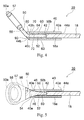
- Fig. 2 is a side view illustrating a configuration of the fishing line guide according to the embodiment of the present invention.
- Fig. 3 is a top view illustrating the configuration of the fishing line guide of Fig. 2 .
- Fig. 4 is a sectional view illustrating the fishing line guide of Fig. 3 taken along line B-B'.
- Fig. 5 is a sectional view illustrating the fishing line guide of Fig. 2 taken along line A-A'.
- Fig. 6 is a front view illustrating the configuration of the fishing line guide of Fig. 2 .
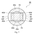
- Fig. 7 is a sectional view illustrating the fishing line guide of Fig. 2 taken along line C-C'.
- the fishing line guide 30 may include mainly a tubular member 40 and a frame member 50 that may be fixed to the tubular member.
- the tubular member 40 may have a tubular shape and a through-hole 42 that may extend along an extension direction thereof may be formed therein.
- the through-hole 42 may be formed to have a substantially constant inner diameter from one end 40a of the tubular member 40 to the other end 40b.
- a tip portion 18a of the top rod 18 may be accommodated in the through-hole 42 from an opening 44a that may be formed at the one end 40a of the tubular member 40.
- the top rod 18 may be fixed to the tubular member 40 as an adhesive is applied between an inner surface of the through-hole 42 of the tubular member 40 and an outer surface of the tip portion 18a of the top rod 18.
- a plurality of (for example, two herein) slits (notches) 46 that may extend along the extension direction of the tubular member 40 while facing each other may be formed on an end surface 40c of the other end 40b.
- each of the two slits 46 may be surrounded by two supporting surfaces 40d and 40e that may extend while facing each other at the other end 40b of the tubular member 40 and a supporting surface 40f that may extend adjacent to the two supporting surfaces 40d and 40e.
- each of the slits 46 may be defined by the three supporting surfaces 40d, 40e, and 40f at the other end 40b of the tubular member 40.
- each of the slits 46 may be adjacent to and may communicate with an opening 44b that may be formed at the other end 40b of the tubular member 40.
- each of the slits 46 may be formed to extend in substantially parallel with the extension direction of the tubular member 40.
- each of the slits 46 may be formed such that the supporting surface 40d and the supporting surface 40e may extend in substantially parallel with each other and to be substantially parallel with the extension direction of the tubular member 40.
- the tubular member 40 may be formed of a fiber-reinforced resin (where a fiber-reinforced resin having a shape of a plurality of sheets may be laminated) in which a reinforced fiber such as glass and carbon is impregnated with a resin.
- the tubular member 40 can be formed by winding a plate-shaped fiber-reinforced resin by a plurality of times.
- the tubular member 40 may be integrally molded by using various metals such as titanium and aluminum and various resins such as epoxy resin, polyamide resin, and phenolic resin.
- the slit 46 can be formed with ease by cutting an end surface of the tubular member 40 with an edged tool, a cutting machine, or the like.
- the frame member 50 may be formed of a plate-shaped member that may, for example, have a width gradually decreasing from one end 50a toward the other end 50b and may be bent in the vicinity of a central portion.
- the frame member 50 may generally have a plate-shaped first supporting portion 52 that may be inserted into the through-hole 42 from the opening 44b of the tubular member 40 to be accommodated therein, a plate-shaped second supporting portion 54 that may be formed in one piece with the first supporting portion 52, may have a width wider than the first supporting portion 52, and may be engaged with the two slits 46 of the tubular member 40, and a plate-shaped main body portion 56 that may be formed in one piece with the second supporting portion 54, may have a width wider than the second supporting portion 54, may extend obliquely with respect to the second supporting portion 54, and may have a through-hole 58 formed therein.
- the frame member 50 may have a substantially constant thickness from the one end 50a to the other end 50b.
- the first supporting portion 52, the second supporting portion 54, and the main body portion 56 may be formed to maintain substantially the same thickness.
- the first supporting portion 52 may be formed to have a width and a thickness that may be smaller than an inner diameter of the through-hole 42 so that the first supporting portion 52 can be accommodated in the through-hole 42 of the tubular member 40.
- the first supporting portion 52 may be formed to have a width that may increase from a front end toward a rear end
- the second supporting portion 54 may be formed to have a thickness that may be smaller than the inner diameter of the through-hole 42 so that the second supporting portion54 can be accommodated in the through-hole 42 of the tubular member 40.
- the second supporting portion 54 may be formed to have a width (width that may increase from a front end toward a rear end) that may be larger than the inner diameter of the through-hole 42.
- the second supporting portion 54 may be formed to have a width that can face the supporting surface 40e (and the supporting surface 40d) of the tubular member 40 at least in part, that is, a width with which the supporting surface 40e (and the supporting surface 40d) can be covered at least in part.
- the main body portion 56 may be formed to have a width that may increase from a front end toward a rear end.
- the main body portion 56 may be shaped to be bent at the front end and to extend obliquely with respect to the second supporting portion 54 (and the first supporting portion 52).
- the main body portion 56 may hold an annular supporting member (may be referred to as a "guide ring") 57 that may have the through-hole 58 at the rear end
- the annular supporting member 57 may serve to insert the fishing line into the through-hole 58 and guide the fishing line.
- the frame member 50 may be formed of a fiber-reinforced resin (where a fiber-reinforced resin having a shape of a plurality of sheets may be laminated) in which a reinforced fiber such as glass and carbon is impregnated with a resin. Furthermore, the frame member 50 may be integrally molded by using various metals such as titanium and aluminum and various resins such as epoxy resin, polyamide resin, and phenolic resin.
- a tip of the first supporting portion 52 of the frame member 50 may be inserted into the through-hole 42 of the tubular member 40 from the opening 44b that may be formed at the other end 40b of the tubular member 40 (at this point of time, the top rod 18 may not be mounted on the tubular member 40).
- the first supporting portion 52 may be moved in the through-hole 42 as it is and a side surface thereof may abut against the inner surface of the through-hole 42 (state illustrated in Fig. 5 ), and cannot be moved any more in the through-hole 42. In this state, as illustrated in Figs.
- a part (edge portion) of a lower surface of the second supporting portion 54 may face (or abut against) the supporting surface 40e of the tubular member 40, and a part (edge portion) of an upper surface of the second supporting portion 54 may face (or abut against) the supporting surface 40d of the tubular member 40.
- a movement of the second supporting portion 54 (in addition, the entire frame member 50) in an up-down direction thereof may be regulated by these supporting surfaces.
- the second supporting portion 54 may be engaged with the two slits 46 of the tubular member 40 (the second supporting portion 54 may be pinched by the supporting surface 40d and the supporting surface 40e of the tubular member 40), the movement of the second supporting portion 54 (and the entire frame member 50) in the up-down direction thereof may be regulated by the slits 46.
- cushioning material 60 may be arranged between an outer surface (that is, an upper surface, a lower surface, a side surface, and the like) of the first supporting portion 52 and the inner surface of the through-hole 42 of the tubular member 40.
- Examples of the cushioning material 60 that may be used may include an adhesive (for example, epoxy resin adhesive) and a resin.
- a cushioning material 70 may be arranged also between an outer surface (that is, an upper surface and a lower surface) of the second supporting portion 54 and the inner surface of the through-hole 42 of the tubular member 40 and the supporting surfaces 40d and 40e.
- the same examples as the cushioning material 60 can be used as the cushioning material 70.
- the cushioning material 60 may serve, first of all, to increase a coupling force between the first supporting portion 52 (second supporting portion 54) and the tubular member 40. Furthermore, the cushioning material 60 (cushioning material 70) may serve to absorb a displacement of the first supporting portion 52 (the second supporting portion 54) in the up-down direction. Specifically, the main body portion 56 may be displaced in the up-down direction as, for example, the fishing line is moved while being in contact with the annular supporting member 57 or as the main body portion 56 collides with an object. In this case, the first supporting portion 52 (second supporting portion 54) may also be displaced in the up-down direction due to the movement of the main body portion 56.
- the cushioning material 60 (cushioning material 70) may be contracted to absorb the displacement of the first supporting portion 52 (second supporting portion 54). In this manner, a situation in which the first supporting portion 52 (second supporting portion 54) and the tubular member 40 may be damaged due to a rapid movement of the main body portion 56 can be suppressed
- an embedded material 80 may be arranged between an upper surface of the main body portion 56 and the end surface 40c of the tubular member 40 so as to fill a step that may be generated between the upper surface of the main body portion 56 of the frame member 50 and the end surface 40c of the other end 40b of the tubular member 40.
- An adhesive, a resin, and the like can be used as the embedded material 80.
- the tubular member 40 itself may constitute the embedded material 80 through processing (fusion welding, welding, or the like) of the end surface 40c of the tubular member 40.
- an embedded material 90 may be arranged also between a lower surface of the main body portion 56 and the end surface 40c of the tubular member 40 so as to fill a step that may be generated between the lower surface of the main body portion 56 of the frame member 50 and the end surface 40c of the other end 40b of the tubular member 40.
- the embedded material 90 can be formed in the same manner as the embedded material 80.
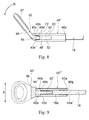
- Fig. 8 is a side view illustrating a configuration of a fishing line guide according to another embodiment of the present invention.
- the same reference numerals are applied to the same elements as illustrated in Fig. 2 and description thereof will be omitted
- a tubular member 40' may have two slits 46' formed on the end surface 40c of the other end 40b.
- the slits 46' may be formed to extend obliquely downward with respect to an extension direction of the tubular member 40'.
- a supporting surface 40d' and a supporting surface 40e' that may surround the slits 46' of the tubular member 40' may be formed to extend obliquely downward with respect to the extension direction of the tubular member 40'.
- a gap between the inner surface of the through-hole 42 of the tubular member 40' and the upper surface (lower surface) of the second supporting portion 54 and the upper surface (lower surface) of the first supporting portion 52 may have a height which may increase (decrease) from the other end 40b of the tubular member 40' toward the one end 40a.
- This may mean an increase in the volume of a cushioning material 70' (cushioning material 60') that may be arranged between the inner surface of the through-hole 42 of the tubular member 40' and the upper surface of the second supporting portion 54 (upper surface of the first supporting portion 52).
- the cushioning material 70' (cushioning material 60') can more effectively reduce the displacement of the second supporting portion 54 (first supporting portion 52) which may be caused by the displacement of the main body portion 56 in the direction illustrated with an arrow R.
- annular supporting member 57 may form with respect to the extension direction of the tubular member 40' can be adjusted by adjusting an angle such that the slit 46' forms with respect to the extension direction of the tubular member 40'. In this manner, guiding of the fishing line by the annular supporting member 57 can be improved
- Fig. 8 illustrates an example in which the slits 46' are formed to extend obliquely downward with respect to the extension direction of the tubular member 40', but the slits 46' may be formed to extend obliquely upward with respect to the extension direction of the tubular member 40'.
- the displacement of the second supporting portion 54 (first supporting portion 52) which may be caused by the displacement of the main body portion 56 in a direction opposite to the direction illustrated with the arrow R can be more effectively reduced.
- Fig. 9 is a sectional view illustrating a configuration of a fishing line guide according to still another embodiment of the present invention viewed from an upper surface.
- the same reference numerals are applied to the same elements as illustrated in Fig. 5 and description thereof will be omitted
- a second supporting portion 54' may have a side surface that may be smoothly connected with an outer surface of a tubular member 40". In this manner, a lower surface (upper surface) of the second supporting portion 54' may completely cover the supporting surface 40e (supporting surface 40d) of the tubular member 40".
- the fishing line guide according to this embodiment may enhance the aesthetically pleasing appearance.
- no step is generated between a side surface of the second supporting portion 54' and an outer surface of the tubular member 40"
- a situation in which the fishing line may be entangled with such a step can be suppressed
- an end surface of a front end of the second supporting portion 54' may form an abutting surface that may abut against the end surface 40c of the other end 40b of the tubular member 40".
- the tubular member 40" may have an inner diameter that may increase toward an end surface 40g of the one end 40a.
- the tubular member 40" may have a substantially constant inner diameter between the other end 40b and the vicinity of a central portion and may have an inner diameter that may increase toward the one end 40a between the vicinity of the central portion and the one end 40a.
- the tip portion 18a of the top rod 18 can be inserted more simply into an opening 44a' that may be formed at the one end 40a of the tubular member 40" (this opening may be larger than the opening 44a illustrated in Fig. 5 ).
- the plurality of slits that may extend while facing each other may be formed on the end surface of the one end of the tubular member, the tip portion of the frame member may be accommodated in the through-hole of the tubular member, and the tip portion of the frame member may be engaged with the plurality of slits of the tubular member such that the tubular member and the frame member may be coupled In this manner, it is possible to provide the fishing line guide that can be manufactured in a simple manner.
- the fishing line guide may not entail any problem in forming both the tubular member and the frame member with the fiber-reinforced resin since the fishing line guide may be manufactured by forming the plurality of slits in the tubular member and engaging the frame member with these slits. In this manner, both the tubular member and the frame member may be formed of the fiber-reinforced resin, and it is possible to provide the fishing line guide which may be capable of having an improved strength and being reduced in weight.
- resistance of the tubular member to external damage can be increased and an external appearance of the tubular member can be improved by applying a resin such as an epoxy resin to the outer surface of the tubular member.
Applications Claiming Priority (2)
| Application Number | Priority Date | Filing Date | Title |
|---|---|---|---|
| JP2012160351A JP5890269B2 (ja) | 2012-07-19 | 2012-07-19 | 釣糸ガイド |
| PCT/JP2013/068974 WO2014013930A1 (fr) | 2012-07-19 | 2013-07-11 | Guide pour ligne de pêche |
Publications (3)
| Publication Number | Publication Date |
|---|---|
| EP2749162A1 true EP2749162A1 (fr) | 2014-07-02 |
| EP2749162A4 EP2749162A4 (fr) | 2015-05-06 |
| EP2749162B1 EP2749162B1 (fr) | 2017-09-13 |
Family
ID=49948759
Family Applications (1)
| Application Number | Title | Priority Date | Filing Date |
|---|---|---|---|
| EP13819879.1A Active EP2749162B1 (fr) | 2012-07-19 | 2013-07-11 | Guide pour ligne de pêche |
Country Status (7)
| Country | Link |
|---|---|
| US (1) | US9949467B2 (fr) |
| EP (1) | EP2749162B1 (fr) |
| JP (1) | JP5890269B2 (fr) |
| KR (1) | KR101892781B1 (fr) |
| CN (1) | CN103841822B (fr) |
| TW (1) | TWI540959B (fr) |
| WO (1) | WO2014013930A1 (fr) |
Families Citing this family (7)
| Publication number | Priority date | Publication date | Assignee | Title |
|---|---|---|---|---|
| KR101521051B1 (ko) * | 2014-05-30 | 2015-05-15 | 후지코교 가부시기가이샤 | 탑가이드용 부착관, 낚싯대용 탑가이드 및 낚싯대 |
| CN105724332B (zh) * | 2014-12-25 | 2019-08-06 | 株式会社岛野 | 钓线引导件、钓竿以及引导框 |
| KR20170050900A (ko) * | 2015-11-02 | 2017-05-11 | 엘지디스플레이 주식회사 | 유기전자장치 |
| JP7026496B2 (ja) * | 2017-12-08 | 2022-02-28 | 株式会社シマノ | トップガイド及び釣竿並びにガイドフレーム |
| JP7133266B2 (ja) * | 2019-02-28 | 2022-09-08 | グローブライド株式会社 | 釣糸ガイド及びその製造方法 |
| KR102262018B1 (ko) * | 2020-03-10 | 2021-06-09 | 후지코교 가부시기가이샤 | 낚싯줄 가이드 및 낚싯줄 가이드를 포함하는 낚싯대 |
| JP2022070301A (ja) * | 2020-10-27 | 2022-05-13 | グローブライド株式会社 | 釣竿 |
Citations (2)
| Publication number | Priority date | Publication date | Assignee | Title |
|---|---|---|---|---|
| FR2087106A5 (fr) * | 1970-05-05 | 1971-12-31 | Garbolino Henri | |
| US5855084A (en) * | 1996-10-17 | 1999-01-05 | Huddleston; J. C. | Fishing pole tip illumination attachment |
Family Cites Families (20)
| Publication number | Priority date | Publication date | Assignee | Title |
|---|---|---|---|---|
| US676554A (en) * | 1901-02-27 | 1901-06-18 | William Friedlander | Tip for fishing-rods. |
| US2601351A (en) * | 1948-06-11 | 1952-06-24 | John L Wilburn | Joining sleeve |
| US2992506A (en) * | 1958-09-19 | 1961-07-18 | Garbolino Henri | Fishing-rod yarn guide ring |
| US3170721A (en) * | 1962-01-18 | 1965-02-23 | Ralph P Wells | Fishing rod sleeve furrule |
| JPS4845353Y1 (fr) * | 1969-08-29 | 1973-12-26 | ||
| JPS5624874U (fr) * | 1979-08-01 | 1981-03-06 | ||
| JPS5624874A (en) | 1979-08-07 | 1981-03-10 | Canon Inc | Scanning unit of original |
| US6092324A (en) * | 1995-05-26 | 2000-07-25 | The Orvis Company, Inc. | Damped fishing rod |
| JP2955503B2 (ja) * | 1995-11-13 | 1999-10-04 | 富士工業株式会社 | 釣竿用トップガイド |
| JP3066312B2 (ja) * | 1996-02-28 | 2000-07-17 | 富士工業株式会社 | 釣竿用導糸環 |
| JP3770349B2 (ja) * | 1996-09-06 | 2006-04-26 | 株式会社シマノ | 中通し竿用糸導入ガイド |
| TW371256B (en) * | 1996-11-12 | 1999-10-01 | Fuji Industries Co Ltd | Line guide for fishing rod |
| KR20000013904A (ko) | 1998-08-14 | 2000-03-06 | 이도연 | 배관이음용 커플링 |
| JP3934452B2 (ja) * | 2002-03-27 | 2007-06-20 | ダイワ精工株式会社 | 外ガイドを有する釣竿 |
| JP4275457B2 (ja) * | 2003-05-16 | 2009-06-10 | 富士工業株式会社 | 釣竿用ガイド |
| US20060032107A1 (en) * | 2004-08-11 | 2006-02-16 | Yu Moon-Jae | Structure of single fishing line guide for fishing rod |
| US7653976B1 (en) * | 2004-09-28 | 2010-02-02 | Kirk David J | Method of repairing a fishing rod |
| JP4652136B2 (ja) * | 2005-06-09 | 2011-03-16 | 富士工業株式会社 | ラインガイド用フレームおよび釣竿 |
| JP4404315B2 (ja) * | 2005-06-30 | 2010-01-27 | グローブライド株式会社 | 釣竿 |
| JP2007289105A (ja) | 2006-04-26 | 2007-11-08 | Shimano Inc | トップガイド |
-
2012
- 2012-07-19 JP JP2012160351A patent/JP5890269B2/ja active Active
-
2013
- 2013-07-05 TW TW102124114A patent/TWI540959B/zh active
- 2013-07-11 WO PCT/JP2013/068974 patent/WO2014013930A1/fr active Application Filing
- 2013-07-11 EP EP13819879.1A patent/EP2749162B1/fr active Active
- 2013-07-11 KR KR1020147000458A patent/KR101892781B1/ko active IP Right Grant
- 2013-07-11 CN CN201380003225.6A patent/CN103841822B/zh active Active
- 2013-07-11 US US14/345,323 patent/US9949467B2/en active Active
Patent Citations (2)
| Publication number | Priority date | Publication date | Assignee | Title |
|---|---|---|---|---|
| FR2087106A5 (fr) * | 1970-05-05 | 1971-12-31 | Garbolino Henri | |
| US5855084A (en) * | 1996-10-17 | 1999-01-05 | Huddleston; J. C. | Fishing pole tip illumination attachment |
Non-Patent Citations (2)
| Title |
|---|
| None * |
| See also references of WO2014013930A1 * |
Also Published As
| Publication number | Publication date |
|---|---|
| EP2749162A4 (fr) | 2015-05-06 |
| WO2014013930A1 (fr) | 2014-01-23 |
| JP5890269B2 (ja) | 2016-03-22 |
| JP2014018152A (ja) | 2014-02-03 |
| US9949467B2 (en) | 2018-04-24 |
| CN103841822A (zh) | 2014-06-04 |
| TWI540959B (zh) | 2016-07-11 |
| US20150201594A1 (en) | 2015-07-23 |
| KR101892781B1 (ko) | 2018-08-28 |
| KR20150034670A (ko) | 2015-04-03 |
| CN103841822B (zh) | 2015-03-25 |
| EP2749162B1 (fr) | 2017-09-13 |
| TW201404300A (zh) | 2014-02-01 |
Similar Documents
| Publication | Publication Date | Title |
|---|---|---|
| EP2749162B1 (fr) | Guide pour ligne de pêche | |
| JP5919448B1 (ja) | 釣り糸ガイド、釣り糸ガイドの製造方法及び釣り糸ガイドを備える釣り竿 | |
| EP2749163B1 (fr) | Canne à pêche | |
| EP2749161B1 (fr) | Guidage de ligne de pêche | |
| JP5777286B2 (ja) | 釣り竿用ラインガイド及び釣り竿 | |
| JP6664723B2 (ja) | 釣り糸ガイド及びこれを備える釣り竿 | |
| EP3078263B1 (fr) | Structure de fixation pour guide de ligne de pêche et canne à pêche | |
| JP5913883B2 (ja) | ケーブル保護案内部材の取付構造 | |
| CN112004412B (zh) | 钓鱼线引导器和配备钓鱼线引导器的钓鱼竿 | |
| JP2016005488A (ja) | 振出竿用ラインガイド及び振出竿 | |
| KR20150026816A (ko) | 낚싯줄 가이드 및 낚싯대 | |
| JP6267853B2 (ja) | 釣糸ガイド | |
| JP2013179870A (ja) | 釣竿 | |
| KR20200098670A (ko) | 로드의 스냅-끼워맞춤에 의한 유지를 위한 장치 | |
| JP6436057B2 (ja) | カバー部材 | |
| JP2005160410A (ja) | 穂先竿 | |
| CN108177161A (zh) | 一种带有芯轴电机的机器人手臂 |
Legal Events
| Date | Code | Title | Description |
|---|---|---|---|
| PUAI | Public reference made under article 153(3) epc to a published international application that has entered the european phase |
Free format text: ORIGINAL CODE: 0009012 |
|
| 17P | Request for examination filed |
Effective date: 20140313 |
|
| AK | Designated contracting states |
Kind code of ref document: A1 Designated state(s): AL AT BE BG CH CY CZ DE DK EE ES FI FR GB GR HR HU IE IS IT LI LT LU LV MC MK MT NL NO PL PT RO RS SE SI SK SM TR |
|
| DAX | Request for extension of the european patent (deleted) | ||
| RA4 | Supplementary search report drawn up and despatched (corrected) |
Effective date: 20150402 |
|
| RIC1 | Information provided on ipc code assigned before grant |
Ipc: A01K 87/04 20060101AFI20150327BHEP |
|
| GRAP | Despatch of communication of intention to grant a patent |
Free format text: ORIGINAL CODE: EPIDOSNIGR1 |
|
| INTG | Intention to grant announced |
Effective date: 20170412 |
|
| GRAS | Grant fee paid |
Free format text: ORIGINAL CODE: EPIDOSNIGR3 |
|
| GRAA | (expected) grant |
Free format text: ORIGINAL CODE: 0009210 |
|
| AK | Designated contracting states |
Kind code of ref document: B1 Designated state(s): AL AT BE BG CH CY CZ DE DK EE ES FI FR GB GR HR HU IE IS IT LI LT LU LV MC MK MT NL NO PL PT RO RS SE SI SK SM TR |
|
| REG | Reference to a national code |
Ref country code: GB Ref legal event code: FG4D |
|
| REG | Reference to a national code |
Ref country code: CH Ref legal event code: EP |
|
| REG | Reference to a national code |
Ref country code: IE Ref legal event code: FG4D |
|
| REG | Reference to a national code |
Ref country code: AT Ref legal event code: REF Ref document number: 927254 Country of ref document: AT Kind code of ref document: T Effective date: 20171015 |
|
| REG | Reference to a national code |
Ref country code: DE Ref legal event code: R096 Ref document number: 602013026679 Country of ref document: DE |
|
| REG | Reference to a national code |
Ref country code: NL Ref legal event code: MP Effective date: 20170913 |
|
| REG | Reference to a national code |
Ref country code: LT Ref legal event code: MG4D |
|
| PG25 | Lapsed in a contracting state [announced via postgrant information from national office to epo] |
Ref country code: NO Free format text: LAPSE BECAUSE OF FAILURE TO SUBMIT A TRANSLATION OF THE DESCRIPTION OR TO PAY THE FEE WITHIN THE PRESCRIBED TIME-LIMIT Effective date: 20171213 Ref country code: SE Free format text: LAPSE BECAUSE OF FAILURE TO SUBMIT A TRANSLATION OF THE DESCRIPTION OR TO PAY THE FEE WITHIN THE PRESCRIBED TIME-LIMIT Effective date: 20170913 Ref country code: HR Free format text: LAPSE BECAUSE OF FAILURE TO SUBMIT A TRANSLATION OF THE DESCRIPTION OR TO PAY THE FEE WITHIN THE PRESCRIBED TIME-LIMIT Effective date: 20170913 Ref country code: FI Free format text: LAPSE BECAUSE OF FAILURE TO SUBMIT A TRANSLATION OF THE DESCRIPTION OR TO PAY THE FEE WITHIN THE PRESCRIBED TIME-LIMIT Effective date: 20170913 Ref country code: LT Free format text: LAPSE BECAUSE OF FAILURE TO SUBMIT A TRANSLATION OF THE DESCRIPTION OR TO PAY THE FEE WITHIN THE PRESCRIBED TIME-LIMIT Effective date: 20170913 |
|
| REG | Reference to a national code |
Ref country code: AT Ref legal event code: MK05 Ref document number: 927254 Country of ref document: AT Kind code of ref document: T Effective date: 20170913 |
|
| PG25 | Lapsed in a contracting state [announced via postgrant information from national office to epo] |
Ref country code: GR Free format text: LAPSE BECAUSE OF FAILURE TO SUBMIT A TRANSLATION OF THE DESCRIPTION OR TO PAY THE FEE WITHIN THE PRESCRIBED TIME-LIMIT Effective date: 20171214 Ref country code: BG Free format text: LAPSE BECAUSE OF FAILURE TO SUBMIT A TRANSLATION OF THE DESCRIPTION OR TO PAY THE FEE WITHIN THE PRESCRIBED TIME-LIMIT Effective date: 20171213 Ref country code: RS Free format text: LAPSE BECAUSE OF FAILURE TO SUBMIT A TRANSLATION OF THE DESCRIPTION OR TO PAY THE FEE WITHIN THE PRESCRIBED TIME-LIMIT Effective date: 20170913 Ref country code: ES Free format text: LAPSE BECAUSE OF FAILURE TO SUBMIT A TRANSLATION OF THE DESCRIPTION OR TO PAY THE FEE WITHIN THE PRESCRIBED TIME-LIMIT Effective date: 20170913 Ref country code: LV Free format text: LAPSE BECAUSE OF FAILURE TO SUBMIT A TRANSLATION OF THE DESCRIPTION OR TO PAY THE FEE WITHIN THE PRESCRIBED TIME-LIMIT Effective date: 20170913 |
|
| PG25 | Lapsed in a contracting state [announced via postgrant information from national office to epo] |
Ref country code: NL Free format text: LAPSE BECAUSE OF FAILURE TO SUBMIT A TRANSLATION OF THE DESCRIPTION OR TO PAY THE FEE WITHIN THE PRESCRIBED TIME-LIMIT Effective date: 20170913 |
|
| PG25 | Lapsed in a contracting state [announced via postgrant information from national office to epo] |
Ref country code: RO Free format text: LAPSE BECAUSE OF FAILURE TO SUBMIT A TRANSLATION OF THE DESCRIPTION OR TO PAY THE FEE WITHIN THE PRESCRIBED TIME-LIMIT Effective date: 20170913 Ref country code: CZ Free format text: LAPSE BECAUSE OF FAILURE TO SUBMIT A TRANSLATION OF THE DESCRIPTION OR TO PAY THE FEE WITHIN THE PRESCRIBED TIME-LIMIT Effective date: 20170913 Ref country code: PL Free format text: LAPSE BECAUSE OF FAILURE TO SUBMIT A TRANSLATION OF THE DESCRIPTION OR TO PAY THE FEE WITHIN THE PRESCRIBED TIME-LIMIT Effective date: 20170913 |
|
| PG25 | Lapsed in a contracting state [announced via postgrant information from national office to epo] |
Ref country code: EE Free format text: LAPSE BECAUSE OF FAILURE TO SUBMIT A TRANSLATION OF THE DESCRIPTION OR TO PAY THE FEE WITHIN THE PRESCRIBED TIME-LIMIT Effective date: 20170913 Ref country code: AT Free format text: LAPSE BECAUSE OF FAILURE TO SUBMIT A TRANSLATION OF THE DESCRIPTION OR TO PAY THE FEE WITHIN THE PRESCRIBED TIME-LIMIT Effective date: 20170913 Ref country code: SK Free format text: LAPSE BECAUSE OF FAILURE TO SUBMIT A TRANSLATION OF THE DESCRIPTION OR TO PAY THE FEE WITHIN THE PRESCRIBED TIME-LIMIT Effective date: 20170913 Ref country code: SM Free format text: LAPSE BECAUSE OF FAILURE TO SUBMIT A TRANSLATION OF THE DESCRIPTION OR TO PAY THE FEE WITHIN THE PRESCRIBED TIME-LIMIT Effective date: 20170913 Ref country code: IS Free format text: LAPSE BECAUSE OF FAILURE TO SUBMIT A TRANSLATION OF THE DESCRIPTION OR TO PAY THE FEE WITHIN THE PRESCRIBED TIME-LIMIT Effective date: 20180113 |
|
| REG | Reference to a national code |
Ref country code: FR Ref legal event code: PLFP Year of fee payment: 6 |
|
| REG | Reference to a national code |
Ref country code: DE Ref legal event code: R097 Ref document number: 602013026679 Country of ref document: DE |
|
| PLBE | No opposition filed within time limit |
Free format text: ORIGINAL CODE: 0009261 |
|
| STAA | Information on the status of an ep patent application or granted ep patent |
Free format text: STATUS: NO OPPOSITION FILED WITHIN TIME LIMIT |
|
| PG25 | Lapsed in a contracting state [announced via postgrant information from national office to epo] |
Ref country code: DK Free format text: LAPSE BECAUSE OF FAILURE TO SUBMIT A TRANSLATION OF THE DESCRIPTION OR TO PAY THE FEE WITHIN THE PRESCRIBED TIME-LIMIT Effective date: 20170913 |
|
| 26N | No opposition filed |
Effective date: 20180614 |
|
| PG25 | Lapsed in a contracting state [announced via postgrant information from national office to epo] |
Ref country code: SI Free format text: LAPSE BECAUSE OF FAILURE TO SUBMIT A TRANSLATION OF THE DESCRIPTION OR TO PAY THE FEE WITHIN THE PRESCRIBED TIME-LIMIT Effective date: 20170913 |
|
| REG | Reference to a national code |
Ref country code: DE Ref legal event code: R119 Ref document number: 602013026679 Country of ref document: DE |
|
| REG | Reference to a national code |
Ref country code: CH Ref legal event code: PL |
|
| PG25 | Lapsed in a contracting state [announced via postgrant information from national office to epo] |
Ref country code: LU Free format text: LAPSE BECAUSE OF NON-PAYMENT OF DUE FEES Effective date: 20180711 Ref country code: MC Free format text: LAPSE BECAUSE OF FAILURE TO SUBMIT A TRANSLATION OF THE DESCRIPTION OR TO PAY THE FEE WITHIN THE PRESCRIBED TIME-LIMIT Effective date: 20170913 |
|
| REG | Reference to a national code |
Ref country code: BE Ref legal event code: MM Effective date: 20180731 |
|
| REG | Reference to a national code |
Ref country code: IE Ref legal event code: MM4A |
|
| PG25 | Lapsed in a contracting state [announced via postgrant information from national office to epo] |
Ref country code: CH Free format text: LAPSE BECAUSE OF NON-PAYMENT OF DUE FEES Effective date: 20180731 Ref country code: DE Free format text: LAPSE BECAUSE OF NON-PAYMENT OF DUE FEES Effective date: 20190201 Ref country code: LI Free format text: LAPSE BECAUSE OF NON-PAYMENT OF DUE FEES Effective date: 20180731 Ref country code: IE Free format text: LAPSE BECAUSE OF NON-PAYMENT OF DUE FEES Effective date: 20180711 |
|
| PG25 | Lapsed in a contracting state [announced via postgrant information from national office to epo] |
Ref country code: BE Free format text: LAPSE BECAUSE OF NON-PAYMENT OF DUE FEES Effective date: 20180731 |
|
| PG25 | Lapsed in a contracting state [announced via postgrant information from national office to epo] |
Ref country code: IT Free format text: LAPSE BECAUSE OF NON-PAYMENT OF DUE FEES Effective date: 20180711 |
|
| PG25 | Lapsed in a contracting state [announced via postgrant information from national office to epo] |
Ref country code: MT Free format text: LAPSE BECAUSE OF NON-PAYMENT OF DUE FEES Effective date: 20180711 |
|
| PG25 | Lapsed in a contracting state [announced via postgrant information from national office to epo] |
Ref country code: TR Free format text: LAPSE BECAUSE OF FAILURE TO SUBMIT A TRANSLATION OF THE DESCRIPTION OR TO PAY THE FEE WITHIN THE PRESCRIBED TIME-LIMIT Effective date: 20170913 |
|
| PG25 | Lapsed in a contracting state [announced via postgrant information from national office to epo] |
Ref country code: HU Free format text: LAPSE BECAUSE OF FAILURE TO SUBMIT A TRANSLATION OF THE DESCRIPTION OR TO PAY THE FEE WITHIN THE PRESCRIBED TIME-LIMIT; INVALID AB INITIO Effective date: 20130711 Ref country code: PT Free format text: LAPSE BECAUSE OF FAILURE TO SUBMIT A TRANSLATION OF THE DESCRIPTION OR TO PAY THE FEE WITHIN THE PRESCRIBED TIME-LIMIT Effective date: 20170913 |
|
| PG25 | Lapsed in a contracting state [announced via postgrant information from national office to epo] |
Ref country code: MK Free format text: LAPSE BECAUSE OF NON-PAYMENT OF DUE FEES Effective date: 20170913 Ref country code: CY Free format text: LAPSE BECAUSE OF FAILURE TO SUBMIT A TRANSLATION OF THE DESCRIPTION OR TO PAY THE FEE WITHIN THE PRESCRIBED TIME-LIMIT Effective date: 20170913 |
|
| PG25 | Lapsed in a contracting state [announced via postgrant information from national office to epo] |
Ref country code: AL Free format text: LAPSE BECAUSE OF FAILURE TO SUBMIT A TRANSLATION OF THE DESCRIPTION OR TO PAY THE FEE WITHIN THE PRESCRIBED TIME-LIMIT Effective date: 20170913 |
|
| P01 | Opt-out of the competence of the unified patent court (upc) registered |
Effective date: 20230512 |
|
| PGFP | Annual fee paid to national office [announced via postgrant information from national office to epo] |
Ref country code: FR Payment date: 20230620 Year of fee payment: 11 |
|
| PGFP | Annual fee paid to national office [announced via postgrant information from national office to epo] |
Ref country code: GB Payment date: 20230601 Year of fee payment: 11 |