EP2720895B1 - Assembly with vapor vent valve and liquid trap for static leak prevention in vapor control system - Google Patents
Assembly with vapor vent valve and liquid trap for static leak prevention in vapor control system Download PDFInfo
- Publication number
- EP2720895B1 EP2720895B1 EP12743212.8A EP12743212A EP2720895B1 EP 2720895 B1 EP2720895 B1 EP 2720895B1 EP 12743212 A EP12743212 A EP 12743212A EP 2720895 B1 EP2720895 B1 EP 2720895B1
- Authority
- EP
- European Patent Office
- Prior art keywords
- assembly
- vapor
- housing
- vent valve
- vent line
- Prior art date
- Legal status (The legal status is an assumption and is not a legal conclusion. Google has not performed a legal analysis and makes no representation as to the accuracy of the status listed.)
- Active
Links
Images

Classifications
-
- B—PERFORMING OPERATIONS; TRANSPORTING
- B60—VEHICLES IN GENERAL
- B60K—ARRANGEMENT OR MOUNTING OF PROPULSION UNITS OR OF TRANSMISSIONS IN VEHICLES; ARRANGEMENT OR MOUNTING OF PLURAL DIVERSE PRIME-MOVERS IN VEHICLES; AUXILIARY DRIVES FOR VEHICLES; INSTRUMENTATION OR DASHBOARDS FOR VEHICLES; ARRANGEMENTS IN CONNECTION WITH COOLING, AIR INTAKE, GAS EXHAUST OR FUEL SUPPLY OF PROPULSION UNITS IN VEHICLES
- B60K15/00—Arrangement in connection with fuel supply of combustion engines or other fuel consuming energy converters, e.g. fuel cells; Mounting or construction of fuel tanks
- B60K15/03—Fuel tanks
- B60K15/035—Fuel tanks characterised by venting means
- B60K15/03519—Valve arrangements in the vent line
-
- B—PERFORMING OPERATIONS; TRANSPORTING
- B60—VEHICLES IN GENERAL
- B60K—ARRANGEMENT OR MOUNTING OF PROPULSION UNITS OR OF TRANSMISSIONS IN VEHICLES; ARRANGEMENT OR MOUNTING OF PLURAL DIVERSE PRIME-MOVERS IN VEHICLES; AUXILIARY DRIVES FOR VEHICLES; INSTRUMENTATION OR DASHBOARDS FOR VEHICLES; ARRANGEMENTS IN CONNECTION WITH COOLING, AIR INTAKE, GAS EXHAUST OR FUEL SUPPLY OF PROPULSION UNITS IN VEHICLES
- B60K15/00—Arrangement in connection with fuel supply of combustion engines or other fuel consuming energy converters, e.g. fuel cells; Mounting or construction of fuel tanks
- B60K15/03—Fuel tanks
- B60K15/035—Fuel tanks characterised by venting means
- B60K15/03504—Fuel tanks characterised by venting means adapted to avoid loss of fuel or fuel vapour, e.g. with vapour recovery systems
- B60K2015/03509—Fuel tanks characterised by venting means adapted to avoid loss of fuel or fuel vapour, e.g. with vapour recovery systems with a droplet separator in the vent line
-
- Y—GENERAL TAGGING OF NEW TECHNOLOGICAL DEVELOPMENTS; GENERAL TAGGING OF CROSS-SECTIONAL TECHNOLOGIES SPANNING OVER SEVERAL SECTIONS OF THE IPC; TECHNICAL SUBJECTS COVERED BY FORMER USPC CROSS-REFERENCE ART COLLECTIONS [XRACs] AND DIGESTS
- Y10—TECHNICAL SUBJECTS COVERED BY FORMER USPC
- Y10T—TECHNICAL SUBJECTS COVERED BY FORMER US CLASSIFICATION
- Y10T137/00—Fluid handling
- Y10T137/0753—Control by change of position or inertia of system
- Y10T137/0874—Vent opening or closing on tipping container
-
- Y—GENERAL TAGGING OF NEW TECHNOLOGICAL DEVELOPMENTS; GENERAL TAGGING OF CROSS-SECTIONAL TECHNOLOGIES SPANNING OVER SEVERAL SECTIONS OF THE IPC; TECHNICAL SUBJECTS COVERED BY FORMER USPC CROSS-REFERENCE ART COLLECTIONS [XRACs] AND DIGESTS
- Y10—TECHNICAL SUBJECTS COVERED BY FORMER USPC
- Y10T—TECHNICAL SUBJECTS COVERED BY FORMER US CLASSIFICATION
- Y10T137/00—Fluid handling
- Y10T137/8593—Systems
- Y10T137/86292—System with plural openings, one a gas vent or access opening
- Y10T137/86324—Tank with gas vent and inlet or outlet
Definitions
- the invention relates to an assembly for a fuel tank vapor control system that prevents liquid fuel from reaching a carbon canister.
- Modem vehicles with internal combustion engines fueled by gasoline typically have a vapor control system that directs fuel vapor from a fuel tank vapor space to a carbon canister, rather than allowing the vapor to vent during refueling or during periods in which the fuel tank temperature rises.
- the canister is periodically purged so that the vapors are burned by the vehicle engine. If such a vehicle is parked on a grade for a prolonged period, liquid fuel may pass through the vapor vent valve to the canister, decreasing the, performance ability of the canister.
- DE 200 19 968 U1 discloses an assembly mountable to a fuel tank within an internal space in the fuel tank and connectable to a carbon canister comprising a housing, a vapor vent valve, a first and a second vent line.
- the housing is arranged within the internal space and defines an internal cavity and has a first port and a second port both in fluid communication with the internal cavity.
- the vapor vent valve is arranged within the internal space and has an inlet and an outlet, wherein the vapor vent valve is configured to permit fluid communication from the fuel tank through the vapor vent valve from the inlet to the outlet when the housing is mounted to the fuel tank.
- the vapor vent valve is isolated from the internal cavity such that fluid flows through the vapor vent valve from the inlet to the outlet without fluid communication with the internal cavity.
- the first vent line is arranged within the internal space and connects the outlet of the vapor vent valve with the first port.
- the second vent line is arranged outside the internal space and is connected to the second port and configured to be operatively connectable with the carbon canister outside the fuel tank. Fluid flow from the fuel tank to the second vent line thereby passes through the vapor vent valve, then through the first vent line, and then through the housing out of the fuel tank.
- An assembly mountable to a fuel tank within an internal space of the fuel tank and connectable to a carbon canister includes a housing within the internal space and defining an internal cavity.
- the housing may be referred to as a liquid trap, and has a first port and a second port both in fluid communication with the internal cavity.
- a vapor vent valve within the internal space and having an inlet and an outlet is configured to permit fluid communication from the fuel tank through the vapor vent valve from the inlet to the outlet.
- the vapor vent valve may be integral with the housing (e.g. , mounted to the housing or formed integrally with the housing), or separate from the housing, but in all cases is isolated from the internal cavity so that fluid flows through the vapor vent valve from the inlet to the outlet without fluid communication with the internal cavity.
- a first vent line within the internal space connects the outlet of the vapor vent valve with the first port of the housing.
- a second vent line within the internal space connects to the second port with the carbon canister. Fluid flow from the fuel tank to the second vent line is thus by a path through the vapor vent valve, then through the first vent line, and then through the housing.
- fluid flow refers to vapor flow.
- the first vent line is configured such that at least a portion of the first vent line is above a predetermined liquid fuel level within the tank when the assembly is mounted to the fuel tank and tilted at up to a predetermined angle. This prevents liquid fuel from reaching the carbon canister when the second vent line is operatively connected to the carbon canister.
- the liquid level in a submerged component that allows liquid into as well as out of the component cannot be higher than the liquid level outside of the component.
- liquid fuel can pass into as well as out of the first vent line through the vapor vent valve, if the first vent line is configured so that at least a portion of the passage in the first vent line is above the fluid level, liquid cannot reach the canister.
- the only route for liquid fuel to pass to the internal cavity of the housing is through the vapor vent valve and the first vent line.
- the routing and length of the first vent line can be specifically designed for each particular fuel tank application so that at least one part of the first vent line is always above a predetermined fuel level when the tank is tilted at up to a predetermined angle.
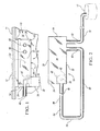
- Figure 1 shows a portion of one embodiment of a vapor control system 10 for a vehicle fuel tank 11.
- the fuel tank 11 has an upper wall portion 12 partially defining an internal space 14.
- An integrated vent valve and liquid trap assembly 16 is mounted to the upper wall portion 12 in the internal space 14.
- the fuel tank 11 holds liquid fuel-.
- Fuel vapor forms in a vapor space above the fuel level, and is routed to a carbon canister 17 operatively connected to the assembly 16 (shown in phantom in Figure 2 ) to prevent vapor emissions.
- the assembly 16 eliminates the possibility of liquid fuel from reaching the carbon canister 17 when the tank 11 is tilted at up to a predetermined angle, such as when a vehicle to which the tank 11 is mounted is parked on a grade.
- the assembly 16 includes a housing 18 and a cap 20.
- the cap 20 is mounted to the upper wall portion 12 of the fuel tank 11 by any known means that maintains the integrity of the fuel tank while meeting applicable emissions standards.
- the upper wall portion 12 may be a top half shell of the fuel tank.
- the cap 20 may be pressed to the upper wall portion 12 after forming the upper wall portion 12, while the upper wall portion 12 is still relatively hot and viscous. This will cause the cap 20 to melt into the upper wall portion 12 so that it effectively becomes hot welded to the upper wall portion 12.
- the cap 20 could have flanges that the hot and viscous upper wall portion 12 flow through to weld the cap to the upper wall portion 12.
- the cap 20 could be formed with an undercut, and the upper wall portion 12 could flow into the undercut when still hot and viscous to weld the cap 20 to the upper wall portion 12.
- the cap 20 could also be mounted through an opening in the upper wall portion 12, rather than to an inner surface of the upper wall portion 12, and hot welded to the upper wall portion 12 at the opening.
- the housing 18 may be injection-molded plastic or any other material that is impervious to both liquid and vapor fuel for which the fuel tank 11 is designed.
- the housing 18 includes four side walls 22, 24, 26, 28, and a bottom wall 30.
- the cap 20 is sealingly engaged with the side walls 22, 24, 26, 28 as further described herein so that the housing 18 and cap 20 together have a generally rectangular box-like shape and define an internal cavity 32.
- the housing 18 may have a variety of other alternative shapes.
- the cap 20 is sealed to the side walls 22, 24, 26, 28 with an O-ring 34.
- a labyrinth seal may be used.
- a hot weld is used. All other forms of welding may be used to connect and seal the housing 18 to the cap 20.
- the assembly 16 also includes one or more vapor vent valves, such as vapor vent valve 36.
- the vapor vent valve 36 is mounted to the housing 18, and may be integrally formed with the housing 18.
- the vapor vent valve 36 is not mounted to the housing 18.
- the vapor vent valve 36 could be separately mounted to the upper wall portion 12.
- the vapor vent valve 36 and housing 18 are configured so that any liquid flow through the vapor vent valve 36 is not in fluid communication with the internal cavity 32.
- the vapor vent valve 36 has an inlet 38 that is open to the vapor space 14. Fluid flows through the vapor vent valve 36 from the inlet 38 to an outlet 40 of the vapor vent valve 36 formed in the side wall 24.
- the housing 18 has additional wall structure 42 that defines the boundaries of the internal space 32 to isolate the vapor vent valve 36 from the internal space 32. Still another possibility is that the valve housing 44 itself isolates the valve 36 from the internal cavity 32.
- the vapor vent valve 36 may be any type of vent valve that controls venting of vapor from the internal space 14 to the canister 17.
- a vapor vent valve 36 is shown in Figure 8 .
- the vapor vent valve 36 has a float 50 that rises with liquid level and eventually prevents liquid from passing from the inlet 38 to the outlet 40.
- a spring 52 helps to keep the float 50 in a position that substantially blocks the outlet 40 when the valve 36 is turned 90 degrees or more. Vapor passes from the inlet 38 to the outlet 40 around the sides of the float 50.
- the housing 18 is formed with a first port 60 and a second port 62.
- the first port 60 and the second port 62 are both formed in the side wall 22.
- the first port 60 and the second port 62 may be formed in any of the side walls 22, 24, 26 and 28 or in the bottom wall 30, and the first port 60 and the second port 62 may be formed in different ones of the walls.
- the assembly 16 includes a first vent line 64 that connects the valve outlet 40 with the first port 60.
- the first vent line 64 is a hollow tube that provides a path for fluid communication from the valve outlet 40 to the first port 60, thus allowing fluid that vents through the valve 36 to pass from the vapor space 14 to the internal cavity 32.
- the first vent line 64 may be a plastic or a metal tube impervious to the fuel in the tank 10.
- the first vent line 64 has a first portion 66, a second portion 68 generally parallel with the first portion 66, and a third portion 70 that connects the first portion 66 with the second portion 68.
- the first portion 66 and the second portion 68 may be at the same level as one another when the tank 11 is level (e.g., at the same level as the center axis of the valve outlet 40 in Figure 1 ) and extending generally parallel with the surface 71 of the bottom portion 30.
- the first vent line 64 is generally U-shaped. In other embodiments, the first vent line 64 may have other shapes.
- the assembly 16 also includes a second vent line 72 that is connected to the second port 62 and extends to and connects with the canister 17.
- the second vent line 72 is also a hollow tube, and provides a path for fluid communication from the second port 62 to the canister 17.
- the second vent line 72 must pass through one of the walls of the tank 11 to reach the canister 17, which may be located near an engine on the vehicle, or elsewhere on the vehicle.
- the vent line 72 may connect with a different vent line that leads from the tank 11 to the canister 17, operatively connecting the second vent line 72 to the canister 17.
- Both of the first and second vent lines 64 and 72 may be any material that is impervious to liquid and vapor fuel.
- intermediate valves and orifices may be inserted along the first vent line 64 or the second vent line 72.
- the single path by which fluid communication is established from the vapor space 14 to the canister 17 is from the valve inlet 38, through the valve 36 to the valve outlet 40, then through the first vent line 64 to the internal cavity 32 of the housing 18, then through the second vent line 72 to the canister 17.
- the vent valve 36 and first vent line 64 establish the only route by which fluid communication is established between the vapor space 14 and the internal cavity 32.
- the first vent line 64 is sized sufficiently so that it extends far enough laterally from the tank 11 so that at least a portion 74 of the first vent line 64 remains above a liquid fuel level 75 in the tank 11 when the tank 11 is tilted at up to a predetermined angle 76 from a level position, such as may be defined with reference to the surface 71 of the bottom wall 30, or with reference to another surface.
- a predetermined angle 76 from a level position, such as may be defined with reference to the surface 71 of the bottom wall 30, or with reference to another surface.
- first vent line 64 can never be higher than the level of liquid outside of the vent line 64 (i.e., the liquid fuel level 75). As such, liquid fuel cannot reach the internal cavity 32 nor reach the second vent line 72, even when these items are submerged below the fuel level 75. Liquid fuel thus cannot pass to the canister 17.
- the first vent line 64 can be routed and sized for different fuel tank applications to achieve this effect. More than one vent valve, inlet port, and outlet port may be used.
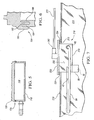
- FIG 5 is a partial illustration of another embodiment of a housing 118 defining an internal cavity 132.
- a vapor vent valve may be mounted to the housing 118, or may be separate, and is in fluid communication with a first port (not shown) in the housing 118 via a first vent line extending between the vapor vent valve and the first port.
- a second port (not shown) extends to the canister 17 of Figure 2 .
- the cap 120 is mounted to the upper portion 12 of the fuel tank 11 of Figure 1 by any of the methods described. The cap 120 is then sealed to the housing 118 with a labyrinth seal 134.
- the labyrinth seal 134 is shown in closer detail in Figure 6 and includes ridges 180, 182 of the cap 120 that interfit with ridges 184, 186 of the housing 118 at an upper perimeter of the housing 118.
- the cap 120 is assembled to the housing 118 before the entire assembly 16 gets mounted into the fuel tank 11 using any possible attachment method. Yet the cap 120 could also be interfit with the housing 118 while the cap 120 is still hot and viscous after mounting to the tank 11 to aid in sealing the cap 120 to the housing 118.
- FIG. 7 shows an embodiment of an assembly 216 configured to function the same as assembly 16, but, as such, does not form a part of the invention as claimed.
- a fuel tank 210 has an opening 219 at which a cap 220 is hot welded at weld areas 234.
- the cap 220 has an integrated second port 262, rather than a second port in housing 218.
- the second port 262 is connected to a second vent line 272 that is in fluid communication with the canister 17 of Figure 2 .
- the housing 218 may be integrally formed with the cap 220, such as by injection molding.
- the housing 218 may be melted to the cap 220 by hot welding, an O-ring seal, a labyrinth seal or otherwise to form an internal cavity 232 similar to cavity 32 of Figure 1 .
- the valve 36 with inlet 38 open to the fuel tank interior space 214 has an outlet 40 connected with first vent line 64 as described above.
- the valve 36 is isolated from the internal cavity 232, so that fluid passes from the inlet 38 to the outlet 40 without entering into the cavity 232.
- the first vent line 64 is shown in slightly perspective view for purposes of illustration. However, as discussed with respect to Figures 3 and 4 , the parallel portions 66, 68 of the first vent line 64 are level with one another in one embodiment.
- the first vent line 64 has a portion that is always above a predetermined liquid fuel level when the tank 210 is tilted at up to a predetermined angle.
Landscapes
- Engineering & Computer Science (AREA)
- Life Sciences & Earth Sciences (AREA)
- Sustainable Development (AREA)
- Sustainable Energy (AREA)
- Chemical & Material Sciences (AREA)
- Combustion & Propulsion (AREA)
- Transportation (AREA)
- Mechanical Engineering (AREA)
- Cooling, Air Intake And Gas Exhaust, And Fuel Tank Arrangements In Propulsion Units (AREA)
- Supplying Secondary Fuel Or The Like To Fuel, Air Or Fuel-Air Mixtures (AREA)
Applications Claiming Priority (2)
| Application Number | Priority Date | Filing Date | Title |
|---|---|---|---|
| US13/162,624 US8485389B2 (en) | 2011-06-17 | 2011-06-17 | Assembly with vapor vent valve and liquid trap for static leak prevention in vapor control system |
| PCT/IB2012/001181 WO2012172419A1 (en) | 2011-06-17 | 2012-06-15 | Assembly with vapor vent valve and liquid trap for static leak prevention in vapor control system |
Publications (2)
| Publication Number | Publication Date |
|---|---|
| EP2720895A1 EP2720895A1 (en) | 2014-04-23 |
| EP2720895B1 true EP2720895B1 (en) | 2015-05-27 |
Family
ID=46604373
Family Applications (1)
| Application Number | Title | Priority Date | Filing Date |
|---|---|---|---|
| EP12743212.8A Active EP2720895B1 (en) | 2011-06-17 | 2012-06-15 | Assembly with vapor vent valve and liquid trap for static leak prevention in vapor control system |
Country Status (6)
Families Citing this family (7)
| Publication number | Priority date | Publication date | Assignee | Title |
|---|---|---|---|---|
| US20140109998A1 (en) * | 2011-05-30 | 2014-04-24 | Volvo Construction Equipment Ab | Fuel tank for heavy construction equipment |
| US8485389B2 (en) * | 2011-06-17 | 2013-07-16 | Eaton Corporation | Assembly with vapor vent valve and liquid trap for static leak prevention in vapor control system |
| US9045038B2 (en) * | 2011-12-22 | 2015-06-02 | Eaton Corporation | Liquid trap with integral jet pump |
| US10253787B2 (en) | 2013-02-01 | 2019-04-09 | Eaton Intelligent Power Limited | Self-aligning jet pump assembly |
| US9168829B2 (en) | 2013-07-17 | 2015-10-27 | Ford Global Technologies, Llc | Vapor storage device having a diffuser plate and dome |
| WO2016130681A1 (en) * | 2015-02-10 | 2016-08-18 | Eaton Corporation | Vent line routing configuration for fuel system |
| CN107660185A (zh) * | 2015-03-29 | 2018-02-02 | 伊顿公司 | 具有通气点阀的燃料系统 |
Family Cites Families (23)
| Publication number | Priority date | Publication date | Assignee | Title |
|---|---|---|---|---|
| US3662780A (en) * | 1967-10-31 | 1972-05-16 | Robert E Marsh | Fluid flow directing structure for pressure vessel |
| DE2912214C2 (de) * | 1979-03-28 | 1983-02-24 | Daimler-Benz Ag, 7000 Stuttgart | Entlüftungseinrichtung für Kraftstofftanks von Fahrzeugen, insbesondere von Kraftfahrzeugen |
| JPH0724611Y2 (ja) * | 1989-05-11 | 1995-06-05 | 本田技研工業株式会社 | 内燃機関における気液分離器の蓋体構造 |
| JP3232471B2 (ja) * | 1995-07-27 | 2001-11-26 | 株式会社ケーヒン | 船用機関における蒸気分離器 |
| JPH11287160A (ja) * | 1998-03-31 | 1999-10-19 | Suzuki Motor Corp | 蒸発燃料回収装置 |
| US6276387B1 (en) * | 1999-06-08 | 2001-08-21 | Delphi Technologies, Inc. | Fuel vapor control apparatus |
| WO2001021991A1 (en) * | 1999-09-22 | 2001-03-29 | Stant Manufacturing Inc. | Fuel tank valve with internal fuel tank vent tube |
| JP2001323854A (ja) * | 2000-03-09 | 2001-11-22 | Toyoda Gosei Co Ltd | 燃料遮断弁およびその製造方法 |
| DE20019968U1 (de) | 2000-11-23 | 2001-02-08 | KAUTEX TEXTRON GmbH & Co. KG, 53229 Bonn | Einrichtung zur Kraftstoffversorgung eines Kfz |
| DE10063414A1 (de) * | 2000-12-19 | 2002-06-27 | Kautex Textron Gmbh & Co Kg | Kraftstoffbehälter |
| DE10209491A1 (de) | 2002-03-05 | 2003-09-18 | Ti Automotive Technology Ct Gm | Kraftstoffbehälter mit Entlüftungssystem |
| DE10227471A1 (de) * | 2002-06-20 | 2004-01-15 | Daimlerchrysler Ag | Kraftstofftankanlage |
| US6895989B2 (en) | 2003-04-15 | 2005-05-24 | Raval-Agriculture Cooperative Societies, Ltd. | Dynamic liquid fuel trap |
| US6883500B2 (en) * | 2003-07-09 | 2005-04-26 | Denso International America, Inc. | Fuel pump module with improved vapor vent manifold |
| CN1856433B (zh) * | 2003-09-09 | 2010-08-18 | 艾伦·约瑟夫·克拉克森 | 分配盖 |
| US20050127078A1 (en) * | 2003-12-11 | 2005-06-16 | Vorenkamp Erich J. | Fuel tank assembly and method of assembly |
| US7475773B2 (en) * | 2005-02-01 | 2009-01-13 | Airsec S.A.S. | Container for moisture-sensitive goods |
| JP2006220081A (ja) * | 2005-02-10 | 2006-08-24 | Hitachi Ltd | 燃料供給装置 |
| DE102005011026B4 (de) | 2005-03-10 | 2014-01-02 | Volkswagen Ag | Einrichtung zur Trennung eines Kraftstoff-/Luftgemischs und Abscheidung von Kraftstoff aus diesem Gemisch |
| JP4492441B2 (ja) * | 2005-05-31 | 2010-06-30 | 豊田合成株式会社 | 気液分離装置 |
| JP5325881B2 (ja) * | 2008-05-12 | 2013-10-23 | 株式会社ミツバ | 燃料ポンプ |
| DE102009049799B4 (de) | 2009-10-16 | 2018-07-12 | Kautex Textron Gmbh & Co. Kg | Kraftstoffbehälter für ein KFZ |
| US8485389B2 (en) * | 2011-06-17 | 2013-07-16 | Eaton Corporation | Assembly with vapor vent valve and liquid trap for static leak prevention in vapor control system |
-
2011
- 2011-06-17 US US13/162,624 patent/US8485389B2/en active Active
-
2012
- 2012-06-15 KR KR20137033206A patent/KR20140029489A/ko not_active Withdrawn
- 2012-06-15 WO PCT/IB2012/001181 patent/WO2012172419A1/en active Application Filing
- 2012-06-15 JP JP2014515302A patent/JP6012722B2/ja active Active
- 2012-06-15 EP EP12743212.8A patent/EP2720895B1/en active Active
- 2012-06-18 CN CN2012203751831U patent/CN202851201U/zh not_active Expired - Fee Related
- 2012-06-18 CN CN2012102688163A patent/CN103147883A/zh active Pending
Also Published As
| Publication number | Publication date |
|---|---|
| WO2012172419A1 (en) | 2012-12-20 |
| US8485389B2 (en) | 2013-07-16 |
| JP2014517206A (ja) | 2014-07-17 |
| CN202851201U (zh) | 2013-04-03 |
| KR20140029489A (ko) | 2014-03-10 |
| CN103147883A (zh) | 2013-06-12 |
| EP2720895A1 (en) | 2014-04-23 |
| JP6012722B2 (ja) | 2016-10-25 |
| US20120318814A1 (en) | 2012-12-20 |
Similar Documents
| Publication | Publication Date | Title |
|---|---|---|
| EP2720895B1 (en) | Assembly with vapor vent valve and liquid trap for static leak prevention in vapor control system | |
| EP2607135B1 (en) | Fuel ventilation system valve | |
| US7047948B2 (en) | Fuel tank | |
| JP6488122B2 (ja) | 燃料タンク用弁装置 | |
| EP1627761A2 (en) | Fuel-dispensing nozzle inhibitor | |
| EP2647516B1 (en) | Method and valve for the venting of a saddle fuel tank | |
| JP2006266267A (ja) | 小型エンジンの燃料蒸発ガスエミッション制御システム及び方法 | |
| US11560049B2 (en) | Fill limit venting valve with high shut-off height | |
| JP4074113B2 (ja) | 燃料タンク用コネクタ | |
| KR102039656B1 (ko) | 연료 탱크용 밸브 장치 | |
| US20070084445A1 (en) | Flange mounted valve manifold | |
| WO2018009849A1 (en) | Electronic fuel tank system venting configuration | |
| CN2584544Y (zh) | 箱盖 | |
| US7891344B2 (en) | Fuel tank | |
| US20050039728A1 (en) | Fuel tank for a motor vehicle | |
| CN105555576B (zh) | 用于给燃料储箱通气的方法和阀门 | |
| KR101701639B1 (ko) | 바디 일체형 밸브를 갖는 흡기 매니폴드 | |
| KR101640547B1 (ko) | 침수 방지 필러넥 패킹 구조 | |
| JPS5921995Y2 (ja) | オ−トバイのブリ−ザ装置 | |
| JP2008221914A (ja) | 車両用燃料タンク | |
| JP2555223Y2 (ja) | 燃料タンクの気液分離チャンバ | |
| CN104061057B (zh) | 内燃机的冷却系统的补偿容器 | |
| KR20040107682A (ko) | 차량용 연료탱크의 증발가스 배출시스템 | |
| GB2335635A (en) | Fuel tank venting | |
| JPH0576840U (ja) | 車両用燃料タンク |
Legal Events
| Date | Code | Title | Description |
|---|---|---|---|
| PUAI | Public reference made under article 153(3) epc to a published international application that has entered the european phase |
Free format text: ORIGINAL CODE: 0009012 |
|
| 17P | Request for examination filed |
Effective date: 20131023 |
|
| AK | Designated contracting states |
Kind code of ref document: A1 Designated state(s): AL AT BE BG CH CY CZ DE DK EE ES FI FR GB GR HR HU IE IS IT LI LT LU LV MC MK MT NL NO PL PT RO RS SE SI SK SM TR |
|
| DAX | Request for extension of the european patent (deleted) | ||
| GRAP | Despatch of communication of intention to grant a patent |
Free format text: ORIGINAL CODE: EPIDOSNIGR1 |
|
| GRAJ | Information related to disapproval of communication of intention to grant by the applicant or resumption of examination proceedings by the epo deleted |
Free format text: ORIGINAL CODE: EPIDOSDIGR1 |
|
| GRAP | Despatch of communication of intention to grant a patent |
Free format text: ORIGINAL CODE: EPIDOSNIGR1 |
|
| INTG | Intention to grant announced |
Effective date: 20150120 |
|
| INTG | Intention to grant announced |
Effective date: 20150128 |
|
| GRAS | Grant fee paid |
Free format text: ORIGINAL CODE: EPIDOSNIGR3 |
|
| GRAA | (expected) grant |
Free format text: ORIGINAL CODE: 0009210 |
|
| AK | Designated contracting states |
Kind code of ref document: B1 Designated state(s): AL AT BE BG CH CY CZ DE DK EE ES FI FR GB GR HR HU IE IS IT LI LT LU LV MC MK MT NL NO PL PT RO RS SE SI SK SM TR |
|
| REG | Reference to a national code |
Ref country code: GB Ref legal event code: FG4D |
|
| REG | Reference to a national code |
Ref country code: CH Ref legal event code: EP |
|
| REG | Reference to a national code |
Ref country code: AT Ref legal event code: REF Ref document number: 728642 Country of ref document: AT Kind code of ref document: T Effective date: 20150615 |
|
| REG | Reference to a national code |
Ref country code: IE Ref legal event code: FG4D |
|
| REG | Reference to a national code |
Ref country code: DE Ref legal event code: R096 Ref document number: 602012007622 Country of ref document: DE Effective date: 20150709 |
|
| REG | Reference to a national code |
Ref country code: SE Ref legal event code: TRGR |
|
| REG | Reference to a national code |
Ref country code: AT Ref legal event code: MK05 Ref document number: 728642 Country of ref document: AT Kind code of ref document: T Effective date: 20150527 |
|
| REG | Reference to a national code |
Ref country code: LT Ref legal event code: MG4D |
|
| PG25 | Lapsed in a contracting state [announced via postgrant information from national office to epo] |
Ref country code: PT Free format text: LAPSE BECAUSE OF FAILURE TO SUBMIT A TRANSLATION OF THE DESCRIPTION OR TO PAY THE FEE WITHIN THE PRESCRIBED TIME-LIMIT Effective date: 20150928 Ref country code: NO Free format text: LAPSE BECAUSE OF FAILURE TO SUBMIT A TRANSLATION OF THE DESCRIPTION OR TO PAY THE FEE WITHIN THE PRESCRIBED TIME-LIMIT Effective date: 20150827 Ref country code: FI Free format text: LAPSE BECAUSE OF FAILURE TO SUBMIT A TRANSLATION OF THE DESCRIPTION OR TO PAY THE FEE WITHIN THE PRESCRIBED TIME-LIMIT Effective date: 20150527 Ref country code: LT Free format text: LAPSE BECAUSE OF FAILURE TO SUBMIT A TRANSLATION OF THE DESCRIPTION OR TO PAY THE FEE WITHIN THE PRESCRIBED TIME-LIMIT Effective date: 20150527 Ref country code: HR Free format text: LAPSE BECAUSE OF FAILURE TO SUBMIT A TRANSLATION OF THE DESCRIPTION OR TO PAY THE FEE WITHIN THE PRESCRIBED TIME-LIMIT Effective date: 20150527 Ref country code: ES Free format text: LAPSE BECAUSE OF FAILURE TO SUBMIT A TRANSLATION OF THE DESCRIPTION OR TO PAY THE FEE WITHIN THE PRESCRIBED TIME-LIMIT Effective date: 20150527 |
|
| REG | Reference to a national code |
Ref country code: NL Ref legal event code: MP Effective date: 20150527 |
|
| PG25 | Lapsed in a contracting state [announced via postgrant information from national office to epo] |
Ref country code: GR Free format text: LAPSE BECAUSE OF FAILURE TO SUBMIT A TRANSLATION OF THE DESCRIPTION OR TO PAY THE FEE WITHIN THE PRESCRIBED TIME-LIMIT Effective date: 20150828 Ref country code: AT Free format text: LAPSE BECAUSE OF FAILURE TO SUBMIT A TRANSLATION OF THE DESCRIPTION OR TO PAY THE FEE WITHIN THE PRESCRIBED TIME-LIMIT Effective date: 20150527 Ref country code: BG Free format text: LAPSE BECAUSE OF FAILURE TO SUBMIT A TRANSLATION OF THE DESCRIPTION OR TO PAY THE FEE WITHIN THE PRESCRIBED TIME-LIMIT Effective date: 20150827 Ref country code: LV Free format text: LAPSE BECAUSE OF FAILURE TO SUBMIT A TRANSLATION OF THE DESCRIPTION OR TO PAY THE FEE WITHIN THE PRESCRIBED TIME-LIMIT Effective date: 20150527 Ref country code: RS Free format text: LAPSE BECAUSE OF FAILURE TO SUBMIT A TRANSLATION OF THE DESCRIPTION OR TO PAY THE FEE WITHIN THE PRESCRIBED TIME-LIMIT Effective date: 20150527 Ref country code: IS Free format text: LAPSE BECAUSE OF FAILURE TO SUBMIT A TRANSLATION OF THE DESCRIPTION OR TO PAY THE FEE WITHIN THE PRESCRIBED TIME-LIMIT Effective date: 20150927 |
|
| PG25 | Lapsed in a contracting state [announced via postgrant information from national office to epo] |
Ref country code: EE Free format text: LAPSE BECAUSE OF FAILURE TO SUBMIT A TRANSLATION OF THE DESCRIPTION OR TO PAY THE FEE WITHIN THE PRESCRIBED TIME-LIMIT Effective date: 20150527 Ref country code: DK Free format text: LAPSE BECAUSE OF FAILURE TO SUBMIT A TRANSLATION OF THE DESCRIPTION OR TO PAY THE FEE WITHIN THE PRESCRIBED TIME-LIMIT Effective date: 20150527 |
|
| REG | Reference to a national code |
Ref country code: CH Ref legal event code: PL |
|
| PG25 | Lapsed in a contracting state [announced via postgrant information from national office to epo] |
Ref country code: SK Free format text: LAPSE BECAUSE OF FAILURE TO SUBMIT A TRANSLATION OF THE DESCRIPTION OR TO PAY THE FEE WITHIN THE PRESCRIBED TIME-LIMIT Effective date: 20150527 Ref country code: RO Free format text: LAPSE BECAUSE OF NON-PAYMENT OF DUE FEES Effective date: 20150527 Ref country code: CZ Free format text: LAPSE BECAUSE OF FAILURE TO SUBMIT A TRANSLATION OF THE DESCRIPTION OR TO PAY THE FEE WITHIN THE PRESCRIBED TIME-LIMIT Effective date: 20150527 Ref country code: MC Free format text: LAPSE BECAUSE OF FAILURE TO SUBMIT A TRANSLATION OF THE DESCRIPTION OR TO PAY THE FEE WITHIN THE PRESCRIBED TIME-LIMIT Effective date: 20150527 Ref country code: PL Free format text: LAPSE BECAUSE OF FAILURE TO SUBMIT A TRANSLATION OF THE DESCRIPTION OR TO PAY THE FEE WITHIN THE PRESCRIBED TIME-LIMIT Effective date: 20150527 |
|
| REG | Reference to a national code |
Ref country code: DE Ref legal event code: R097 Ref document number: 602012007622 Country of ref document: DE |
|
| REG | Reference to a national code |
Ref country code: IE Ref legal event code: MM4A |
|
| PLBE | No opposition filed within time limit |
Free format text: ORIGINAL CODE: 0009261 |
|
| STAA | Information on the status of an ep patent application or granted ep patent |
Free format text: STATUS: NO OPPOSITION FILED WITHIN TIME LIMIT |
|
| PG25 | Lapsed in a contracting state [announced via postgrant information from national office to epo] |
Ref country code: LI Free format text: LAPSE BECAUSE OF NON-PAYMENT OF DUE FEES Effective date: 20150630 Ref country code: CH Free format text: LAPSE BECAUSE OF NON-PAYMENT OF DUE FEES Effective date: 20150630 Ref country code: IE Free format text: LAPSE BECAUSE OF NON-PAYMENT OF DUE FEES Effective date: 20150615 |
|
| 26N | No opposition filed |
Effective date: 20160301 |
|
| PG25 | Lapsed in a contracting state [announced via postgrant information from national office to epo] |
Ref country code: SI Free format text: LAPSE BECAUSE OF FAILURE TO SUBMIT A TRANSLATION OF THE DESCRIPTION OR TO PAY THE FEE WITHIN THE PRESCRIBED TIME-LIMIT Effective date: 20150527 |
|
| REG | Reference to a national code |
Ref country code: FR Ref legal event code: PLFP Year of fee payment: 5 |
|
| PG25 | Lapsed in a contracting state [announced via postgrant information from national office to epo] |
Ref country code: BE Free format text: LAPSE BECAUSE OF FAILURE TO SUBMIT A TRANSLATION OF THE DESCRIPTION OR TO PAY THE FEE WITHIN THE PRESCRIBED TIME-LIMIT Effective date: 20150527 |
|
| PG25 | Lapsed in a contracting state [announced via postgrant information from national office to epo] |
Ref country code: MT Free format text: LAPSE BECAUSE OF FAILURE TO SUBMIT A TRANSLATION OF THE DESCRIPTION OR TO PAY THE FEE WITHIN THE PRESCRIBED TIME-LIMIT Effective date: 20150527 |
|
| REG | Reference to a national code |
Ref country code: FR Ref legal event code: PLFP Year of fee payment: 6 |
|
| PG25 | Lapsed in a contracting state [announced via postgrant information from national office to epo] |
Ref country code: HU Free format text: LAPSE BECAUSE OF FAILURE TO SUBMIT A TRANSLATION OF THE DESCRIPTION OR TO PAY THE FEE WITHIN THE PRESCRIBED TIME-LIMIT; INVALID AB INITIO Effective date: 20120615 Ref country code: SM Free format text: LAPSE BECAUSE OF FAILURE TO SUBMIT A TRANSLATION OF THE DESCRIPTION OR TO PAY THE FEE WITHIN THE PRESCRIBED TIME-LIMIT Effective date: 20150527 |
|
| PG25 | Lapsed in a contracting state [announced via postgrant information from national office to epo] |
Ref country code: CY Free format text: LAPSE BECAUSE OF FAILURE TO SUBMIT A TRANSLATION OF THE DESCRIPTION OR TO PAY THE FEE WITHIN THE PRESCRIBED TIME-LIMIT Effective date: 20150527 Ref country code: NL Free format text: LAPSE BECAUSE OF FAILURE TO SUBMIT A TRANSLATION OF THE DESCRIPTION OR TO PAY THE FEE WITHIN THE PRESCRIBED TIME-LIMIT Effective date: 20150527 |
|
| PG25 | Lapsed in a contracting state [announced via postgrant information from national office to epo] |
Ref country code: TR Free format text: LAPSE BECAUSE OF FAILURE TO SUBMIT A TRANSLATION OF THE DESCRIPTION OR TO PAY THE FEE WITHIN THE PRESCRIBED TIME-LIMIT Effective date: 20150527 |
|
| PG25 | Lapsed in a contracting state [announced via postgrant information from national office to epo] |
Ref country code: LU Free format text: LAPSE BECAUSE OF NON-PAYMENT OF DUE FEES Effective date: 20150615 |
|
| REG | Reference to a national code |
Ref country code: FR Ref legal event code: PLFP Year of fee payment: 7 |
|
| PG25 | Lapsed in a contracting state [announced via postgrant information from national office to epo] |
Ref country code: MK Free format text: LAPSE BECAUSE OF FAILURE TO SUBMIT A TRANSLATION OF THE DESCRIPTION OR TO PAY THE FEE WITHIN THE PRESCRIBED TIME-LIMIT Effective date: 20150527 |
|
| PG25 | Lapsed in a contracting state [announced via postgrant information from national office to epo] |
Ref country code: AL Free format text: LAPSE BECAUSE OF FAILURE TO SUBMIT A TRANSLATION OF THE DESCRIPTION OR TO PAY THE FEE WITHIN THE PRESCRIBED TIME-LIMIT Effective date: 20150527 |
|
| REG | Reference to a national code |
Ref country code: GB Ref legal event code: 732E Free format text: REGISTERED BETWEEN 20181115 AND 20181130 |
|
| REG | Reference to a national code |
Ref country code: DE Ref legal event code: R081 Ref document number: 602012007622 Country of ref document: DE Owner name: EATON INTELLIGENT POWER LIMITED, IE Free format text: FORMER OWNER: EATON CORP., CLEVELAND, OHIO, US |
|
| P01 | Opt-out of the competence of the unified patent court (upc) registered |
Effective date: 20230521 |
|
| PGFP | Annual fee paid to national office [announced via postgrant information from national office to epo] |
Ref country code: DE Payment date: 20250520 Year of fee payment: 14 |
|
| PGFP | Annual fee paid to national office [announced via postgrant information from national office to epo] |
Ref country code: GB Payment date: 20250520 Year of fee payment: 14 |
|
| PGFP | Annual fee paid to national office [announced via postgrant information from national office to epo] |
Ref country code: IT Payment date: 20250520 Year of fee payment: 14 |
|
| PGFP | Annual fee paid to national office [announced via postgrant information from national office to epo] |
Ref country code: FR Payment date: 20250520 Year of fee payment: 14 |
|
| PGFP | Annual fee paid to national office [announced via postgrant information from national office to epo] |
Ref country code: SE Payment date: 20250520 Year of fee payment: 14 |