EP2708391A2 - Gehäuse für eine Heizungs- und/oder Klimaanlage insbesondere für Fahrzeuge - Google Patents
Gehäuse für eine Heizungs- und/oder Klimaanlage insbesondere für Fahrzeuge Download PDFInfo
- Publication number
- EP2708391A2 EP2708391A2 EP13001934.2A EP13001934A EP2708391A2 EP 2708391 A2 EP2708391 A2 EP 2708391A2 EP 13001934 A EP13001934 A EP 13001934A EP 2708391 A2 EP2708391 A2 EP 2708391A2
- Authority
- EP
- European Patent Office
- Prior art keywords
- housing
- air
- valve element
- opening
- normal operating
- Prior art date
- Legal status (The legal status is an assumption and is not a legal conclusion. Google has not performed a legal analysis and makes no representation as to the accuracy of the status listed.)
- Granted
Links
Images

Classifications
-
- B—PERFORMING OPERATIONS; TRANSPORTING
- B60—VEHICLES IN GENERAL
- B60H—ARRANGEMENTS OF HEATING, COOLING, VENTILATING OR OTHER AIR-TREATING DEVICES SPECIALLY ADAPTED FOR PASSENGER OR GOODS SPACES OF VEHICLES
- B60H1/00—Heating, cooling or ventilating devices
- B60H1/00007—Combined heating, ventilating, or cooling devices
- B60H1/00021—Air flow details of HVAC devices
- B60H1/00028—Constructional lay-out of the devices in the vehicle
-
- B—PERFORMING OPERATIONS; TRANSPORTING
- B60—VEHICLES IN GENERAL
- B60H—ARRANGEMENTS OF HEATING, COOLING, VENTILATING OR OTHER AIR-TREATING DEVICES SPECIALLY ADAPTED FOR PASSENGER OR GOODS SPACES OF VEHICLES
- B60H1/00—Heating, cooling or ventilating devices
-
- B—PERFORMING OPERATIONS; TRANSPORTING
- B60—VEHICLES IN GENERAL
- B60H—ARRANGEMENTS OF HEATING, COOLING, VENTILATING OR OTHER AIR-TREATING DEVICES SPECIALLY ADAPTED FOR PASSENGER OR GOODS SPACES OF VEHICLES
- B60H1/00—Heating, cooling or ventilating devices
- B60H1/00007—Combined heating, ventilating, or cooling devices
- B60H1/00021—Air flow details of HVAC devices
- B60H2001/00078—Assembling, manufacturing or layout details
- B60H2001/00085—Assembling, manufacturing or layout details of air intake
Definitions
- the present invention relates to an air-conducting housing for a heating and / or air conditioning, in particular for vehicles, according to the preamble of claim 1. Furthermore, the invention relates to a method for operating a heating and / or air conditioning, in particular for motor vehicles, with an air-conveying Housing according to the preamble of claim 11.
- Heating and / or air conditioning systems are used to condition the air in interiors, wherein in particular the maintenance of clear visibility of the windows is essential, especially in motor vehicles.
- a circulation control in which usually closed the fresh air intake for a short time and an opening into the interior short-circuit opening is opened (faster heating of the interior, etc.).
- the air conditioning may possibly be impaired or even completely interrupted by environmental influences, such as icing of the intake opening in winter or by foreign bodies (leaves, etc.) in the intake opening.
- the object of the invention is therefore to propose an air-conducting housing for a heating and / or air conditioning system and a method for operating a heating and / or air conditioning with an air-guiding housing in which disturbances in the fresh air supply can be counteracted with simple means.
- an air-bearing housing for a heating and / or air conditioning, in particular for a heating and / or air conditioning for motor vehicles or commercial vehicles, with at least one housing-side inlet and / or suction port proposed for air, wherein the inlet and / or suction is formed in particular as a fresh air intake opening.
- At least one valve element is arranged in at least one wall of the housing, which is designed so that it can in a defined or predetermined normal operating state (which may of course also include several different operating states), in addition to at least one inlet and / or intake opening closes existing additional air opening and at defined or predetermined, compared to the normal operating state changed flow and / or pressure conditions in the housing, in particular at defined negative pressure conditions in the housing, opens and the associated additional air opening releases so that flow through this additional air into the housing can.
- a defined or predetermined normal operating state which may of course also include several different operating states
- Such influencing the performance of the heating and / or air conditioning flow and / or pressure conditions, in particular a negative pressure in the housing at a blower suction, can be adjusted without the inventive solution, for example, when the Ansaugquer bain the inflow and / or suction reduced , For example, by icing and / or by there accumulating foreign body.
- heating and / or air conditioning or the air-conducting housing can be coupled in a conventional manner with a blower, which is preferably integrated into this or in this.
- the valve element itself can be formed for example by a kind of check valve, which is closed with a low biasing force and opens at defined flow and in particular pressure changes in the housing, for example due to a reduced Ansaugqueritess, and the associated additional air opening releases.
- the additional air opening can be arranged away from the regular intake opening, for example on a rear wall of a housing, so that it preferably supplies fresh air as additional air.
- This at least one valve element can thus be ensured in a simple manner that, for example due to environmental influences such as icing in winter and / or by foreign bodies (leaves, etc.) deteriorates the air conditioning or possibly even completely interrupted.
- the valve element can be designed as a valve element that can be actuated with a control and / or regulating device, in particular by means of a control unit, which is controlled, for example after the detection of defined pressure changes with a suitable sensor device, in order to release the respectively assigned additional air opening.
- a control unit which is controlled, for example after the detection of defined pressure changes with a suitable sensor device, in order to release the respectively assigned additional air opening.
- only a portion of the valve elements may optionally be opened in such a case.
- such a structure is relatively expensive. Therefore, an embodiment in which the valve element opens automatically at defined or predetermined flow and / or pressure conditions in the housing compared to the normal operating state, for example at a defined negative pressure in the housing, is particularly preferred.
- the valve element is formed by a particularly montage- and cost-effective, at least partially rubber-elastic trained cover and / or umbrella valve, the one off the associated additional air opening in the normal operating state and / or overlapping, preferably umbrella-like off and / or overlapping, and at the defined predetermined, compared to the normal operating state changed flow and / or pressure ratios releasing cover and / or screen element has.
- a cover and / or screen element is preferably formed by a sealing cap or lip.
- valve element in a zusatz Kunststoffö Maschinens workede recording in particular in a central receptacle or bore of the associated additional air opening, arranged and / or is inserted, for example by means of a clip connection is clipped.
- the additional air opening is formed by a plurality of spaced around the central bore, spaced openings formed by the preferably circumferential cover and / or screen element , In particular, a sealing cap or a sealing lip, which forms, for example, a head of the cover and / or umbrella valve, are covered in the closed state.
- the additional air opening can also be formed only by a single breakthrough, which then circulates, for example, only in regions around the central receptacle.
- valve element it may be sufficient that a single valve element is provided.
- the at least one valve element can be arranged in one of the inlet and / or intake opening, in particular a fresh air intake opening, opposite wall portion of the housing.
- This causes the regular inflowing air or fresh air impinges more or less directly on the valve element such that the inflowing air, preferably at least supporting, in the direction of its closed position, preferably maintains the valve element.
- the dynamic pressure occurring due to the inflowing air can also be included in the structural design of the valve element or keep it closed in a targeted manner. This also possibly results in an improved tuning of the response of the valve element due to larger, not only caused by the blower pressure differences.
- the inlet and / or intake opening in particular a fresh air intake opening, may be particularly preferably positioned such that it is directly or indirectly exposed to the airstream.
- the back pressure that normally occurs due to the airstream can be included in the constructive design of the valve element or it can be kept closed in a targeted manner.
- the housing may be formed by an air filter housing having at least one correspondingly integrated valve element whose fresh air intake opening is positioned behind a correspondingly formed front apron with a radiator grille.
- the air filter housing 1 is shown for an air conditioning system of a motor vehicle, which is arranged behind a front apron (not shown).
- an electrically driven blower 2 is integrated in the housing 1.
- the blower 2 can also be provided at a different location in the air ducts and air conditioning devices, not shown, to the interior of the motor vehicle.
- a fresh air intake opening 3 is provided, via which the fresh air in the housing 1 with the integrated air filter (not shown) can be introduced.
- the fresh air intake opening 3 is preferably arranged on the front wall 4 of the housing 1 behind a radiator grille of the front apron and accordingly when driving the wind (arrows 5) exposed.
- umbrella valves 7 On the rear wall 6 of the housing 1 a plurality of umbrella valves 7 are provided, which cover these associated additional air openings 8 in the rear wall 6.
- the umbrella valves 7 lie opposite the intake opening 3, so are the back pressure of the wind or the fresh air flow even with fan operation (see. Fig. 2 ) exposed.
- the umbrella valves 7 made of a rubber-elastic material, for example of an elastomer, here have larger diameter heads 7a with circumferential sealing lips as sealing caps and integrally formed on the heads 7a, central pin 7b.
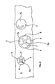
- each valve 7 ( Fig. 3 ) centric recesses or holes 6a and around this only four exemplary, the additional air openings 8 forming openings provided.
- the correspondingly formed pin 7b of the valves 7 can be easily clipped mounting, the heads 7a of the valves 7 rest against the rear wall 6 and cover the openings 8 with a predetermined biasing force.
- the Fig. 1 shows the driving operation of the motor vehicle with activated or possibly not switched on fan 2 and with free fresh air intake 3, the cross section is not reduced.
- the valves 7 are closed; the fresh air intake takes place exclusively via the intake opening 3.
- the Fig. 2 exemplifies an irregular state with respect to the normal operating state changed flow and / or pressure conditions, in which the fresh air intake port 3 is more or less closed by, for example, icing 3a and / or analogous foreign body.
- the valves 7 Open here by the changed negative pressure conditions in the housing 1 and the lack of dynamic pressure (arrows 5) of the wind, the valves 7 automatically and it can additional fresh air, for example from the environment, to flow into the air conditioner or in the housing 1.
- valves 7 instead of the umbrella valves 7, if necessary, other types of valves with the described effect can also be used. If appropriate, the valve elements 7 with additional air openings 8 can also be used in an exclusive heating system.
- the housing 1 may optionally also be the housing of the heating and / or air conditioning with integrated fan 2 and the usual, downstream air conditioning devices.
Landscapes
- Physics & Mathematics (AREA)
- Thermal Sciences (AREA)
- Engineering & Computer Science (AREA)
- Mechanical Engineering (AREA)
- Air-Conditioning For Vehicles (AREA)
Abstract
Description
- Die vorliegende Erfindung betrifft ein luftführendes Gehäuse für eine Heizungs- und/oder Klimaanlage, insbesondere für Fahrzeuge, gemäß dem Oberbegriff des Patentanspruchs 1. Ferner betrifft die Erfindung ein Verfahren zum Betreiben einer Heizungs- und/oder Klimaanlage, insbesondere für Kraftfahrzeuge, mit einem luftführenden Gehäuse nach dem Oberbegriff des Anspruchs 11.
- Heizungs- und/oder Klimaanlagen dienen zur Konditionierung der Luft in Innenräumen, wobei insbesondere bei Kraftfahrzeugen auch die Aufrechterhaltung klarer Sichtverhältnisse an den Scheiben wesentlich ist. Bei solchen Anlagen ist es auch bekannt, eine Umlaufsteuerung vorzusehen, bei der meist kurzzeitig die Frischluft-Ansaugöffnung geschlossen und eine in den Innenraum mündende Kurzschlussöffnung aufgesteuert wird (schnellere Erwärmung des Innenraums, etc.). Bei derartigen Heizungs- und/oder Klimaanlagen kann gegebenenfalls durch Umwelteinflüsse, wie zum Beispiel Vereisung der Ansaugöffnung im Winter oder durch Fremdkörper (Blätter, etc.) in der Ansaugöffnung die Luftkonditionierung verschlechtert oder sogar ganz unterbrochen sein.
- Aufgabe der Erfindung ist es daher, ein luftführendes Gehäuse für eine Heizungs- und/oder Klimaanlage sowie ein Verfahren zum Betreiben einer Heizungs- und/oder Klimaanlage mit einem luftführenden Gehäuse vorzuschlagen, bei dem mit einfachen Mitteln Störungen in der Frischluftzuführung entgegengewirkt werden kann.
- Die Lösung dieser Aufgabe gelingt mit den Merkmalen der unabhängigen Patentansprüche. Vorteilhafte und besonders zweckmäßige Ausgestaltungen der Erfindung sind Gegenstand der Unteransprüche.
- Gemäß Patentanspruch 1 wird ein luftführendes Gehäuse für eine Heizungs- und/oder Klimaanlage, insbesondere für eine Heizungs- und/oder Klimaanlage für Kraftfahrzeuge bzw. Nutzfahrzeuge, mit zumindest einer gehäuseseitigen Einlass- und/oder Ansaugöffnung für Luft vorgeschlagen, wobei die Einlass- und/oder Ansaugöffnung insbesondere als Frischluft-Ansaugöffnung ausgebildet ist. Erfindungsgemäß ist vorgesehen, dass in zumindest einer Wand des Gehäuses zumindest ein Ventilelement angeordnet ist, das so ausgebildet ist, dass es in einem definierten bzw. vorgegebenen Normalbetriebszustand (der selbstverständlich auch mehrere unterschiedliche Betriebszustände umfassen kann) eine, zusätzlich zur zumindest einen Einlass- und/oder Ansaugöffnung vorhandene Zusatzluftöffnung verschließt und bei definierten bzw. vorgegebenen, gegenüber dem Normalbetriebszustand veränderten Strömungs- und/oder Druckverhältnissen in dem Gehäuse, insbesondere bei definierten Unterdruckverhältnissen in dem Gehäuse, öffnet und die zugeordnete Zusatzluftöffnung freigibt, damit über diese Zusatzluft in das Gehäuse einströmen kann. Derartige die Leistung der Heizungs- und/oder Klimaanlage beeinträchtigende Strömungs- und/oder Druckverhältnisse, insbesondere ein Unterdruck im Gehäuse bei einer Gebläseansaugung, können sich ohne die erfindungsgemäße Lösung zum Beispiel dann einstellen, wenn sich der Ansaugquerschnitt der Einström- und/oder Ansaugöffnung vermindert, zum Beispiel durch Vereisung und/oder durch sich dort ansammelnde Fremdkörper.
- Es versteht sich, dass die Heizungs- und/oder Klimaanlage bzw. das luftführende Gehäuse in an sich bekannter Weise mit einem Gebläse gekoppelt sein kann, das vorzugsweise in diese bzw. in dieses integriert ist.
- Das Ventilelement selbst kann zum Beispiel durch eine Art Rückschlagventil gebildet sein, das unter geringer Vorspannkraft geschlossen ist und bei definierten Strömungs- und insbesondere Druckänderungen in dem Gehäuse, zum Beispiel aufgrund eines verminderten Ansaugquerschnitts, öffnet und die zugeordnete Zusatzluftöffnung freigibt. Die Zusatzluftöffnung kann dabei von der regulären Ansaugöffnung entfernt, zum Beispiel an einer Rückwand eines Gehäuses, so angeordnet sein, dass sie bevorzugt Frischluft als Zusatzluft zuführt. Durch dieses zumindest eine Ventilelement kann somit auf einfache Weise sichergestellt werden, dass nicht zum Beispiel durch Umwelteinflüsse wie Vereisung im Winter und/oder durch Fremdkörper (Blätter, etc.) die Luftkonditionierung verschlechtert oder gegebenenfalls sogar ganz unterbrochen ist.
- Das Ventilelement kann grundsätzlich als mit einer Steuer- und/oder Regeleinrichtung, insbesondere mittels eines Steuergerätes, ansteuerbares Ventilelement ausgebildet sein, das, beispielsweise nach dem Erfassen von definierten Druckänderungen mit einer geeigneten Sensoreinrichtung, aufgesteuert wird, um die jeweils zugeordnete Zusatzluftöffnung freizugeben. In Verbindung mit mehreren Ventilelementen und mehreren Zusatzluftöffnungen kann in einem solchen Fall gegebenenfalls auch nur ein Teil der Ventilelemente aufgesteuert werden. Ein derartiger Aufbau ist jedoch relativ aufwendig. Besonders bevorzugt ist daher eine Ausgestaltung, bei der das Ventilelement bei definierten bzw. vorgegebenen, gegenüber dem Normalbetriebszustand veränderten Strömungs- und/oder Druckverhältnissen in dem Gehäuse, zum Beispiel bei einem definierten Unterdruck in dem Gehäuse, selbsttätig öffnet. In diesem Zusammenhang ist gemäß einer besonders bevorzugten konkreten Ausgestaltung vorgesehen, dass das Ventilelement durch ein besonders montage- und kostengünstiges, wenigstens bereichsweise gummielastisch ausgebildetes Abdeck- und/oder Schirmventil gebildet ist, das ein die zugeordnete Zusatzluftöffnung im Normalbetriebszustand ab- und/oder überdeckendes, vorzugsweise schirmartig ab- und/oder überdeckendes, und bei den definiert vorgegebenen, gegenüber dem Normalbetriebszustand veränderten Strömungs- und/oder Druckverhältnissen freigebendes Abdeck- und/oder Schirmelement aufweist. Ein derartiges Abdeck- und/oder Schirmelement ist bevorzugt durch eine Dichtkappe bzw. -lippe gebildet.
- Besonders bevorzugt ist eine konkrete Ausgestaltung gemäß der das Ventilelement in einer zusatzluftöffnungsseitige Aufnahme, insbesondere in einer zentrischen Aufnahme bzw. Bohrung der zugeordneten Zusatzluftöffnung, angeordnet und/oder eingesetzt ist, zum Beispiel mittels einer Clipverbindung eingeclipst ist. Insbesondere in Verbindung mit einer derartigen Ausgestaltung, aber nicht ausschließlich mit einer derartigen Ausgestaltung, ist es vorteilhaft, wenn die Zusatzluftöffnung durch mehrere, um die zentrische Bohrung herum angeordnete, voneinander beabstandete Durchbrüche gebildet ist, die von dem vorzugsweise umlaufenden Abdeck- und/oder Schirmelement, insbesondere einer Dichtkappe bzw. einer Dichtlippe, das zum Beispiel einen Kopf des Abdeck- und/oder Schirmventils ausbildet, im geschlossenem Zustand überdeckt sind. Grundsätzlich kann die Zusatzluftöffnung aber auch nur durch einen einzigen Durchbruch gebildet sein, der dann zum Beispiel lediglich bereichsweise um die zentrische Aufnahme umläuft.
- Grundsätzlich kann es ausreichend sein, dass ein einziges Ventilelement vorgesehen ist. Besonders bevorzugt ist jedoch eine Ausgestaltung, bei der in der Wand des Gehäuses mehrere voneinander beabstandete, jeweils eine oder mehrere zugeordnete Zusatzöffnungen abdeckende Ventilelemente vorgesehen sind, da dadurch ausreichend große Querschnitte bereitgestellt werden können, die sich bei Bedarf automatisch zuschalten.
- In einer vorteilhaften Weiterbildung der Erfindung kann das zumindest eine Ventilelement in einem der Einlass- und/oder Ansaugöffnung, insbesondere einer Frischluft-Ansaugöffnung, gegenüberliegenden Wandabschnitt des Gehäuses angeordnet sein. Damit wird bewirkt, dass die regulär einströmende Luft bzw. Frischluft mehr oder weniger direkt auf das Ventilelement auftrifft dergestalt, dass die einströmende Luft das Ventilelement, zumindest unterstützend, in Richtung dessen Geschlossenstellung beaufschlagt und/oder vorspannt, bevorzugt dieses zuhält. Damit kann auch der durch die einströmende Luft auftretende Staudruck in die konstruktive Auslegung des Ventilelementes mit einbezogen sein bzw. dieses gezielt geschlossen halten. Daraus resultiert gegebenenfalls auch eine verbesserte Abstimmung des Ansprechverhaltens des Ventilelementes aufgrund größerer, nicht nur durch die Gebläseleistung bewirkter Druckunterschiede.
- Bei einem Kraftfahrzeug kann besonders bevorzugt die Einlass- und/oder Ansaugöffnung, insbesondere eine Frischluft-Ansaugöffnung, derart positioniert sein, dass sie mittelbar oder unmittelbar dem Fahrtwind ausgesetzt ist. Damit kann somit konkret der durch den Fahrtwind regulär auftretende Staudruck in die konstruktive Auslegung des Ventilelementes einbezogen sein bzw. dieses gezielt geschlossen halten.
- Schließlich kann, zum Beispiel bei einem Nutzfahrzeug, das Gehäuse durch ein Luftfiltergehäuse mit wenigstens einem entsprechend integrierten Ventilelement gebildet sein, dessen Frischluft-Ansaugöffnung hinter einer entsprechend ausgebildeten Frontschürze mit Kühlergrill positioniert ist.
- Die sich mit der erfindungsgemäßen Verfahrensführung ergebenden Vorteile wurden bereits zuvor ausführlich beschrieben, so dass zur Vermeidung von Wiederholungen auf die zuvor gemachten Ausführungen verwiesen wird.
- Ein Ausführungsbeispiel der Erfindung ist anhand der beigefügten, skizzenhaften Zeichnung näher erläutert.
- Es zeigen:
- Fig. 1
- einen Schnitt durch ein, einer Klimaanlage für ein Kraftfahrzeug vorgeschaltetes Luftfiltergehäuse mit einem integrierten Gebläse, einer Frischluft-Ansaugöffnung und mit an der Rückwand des Gehäuses angeordneten Schirmventilen zur Zuführung von Zusatzluft;
- Fig. 2
- das Gehäuse nach
Fig. 1 bei geöffneten Schirmventilen und Zuführung von zusätzlicher Frischluft; und - Fig. 3
- in vergrößerter Darstellung die Zusatzluftöffnungen mit teils montierten Schirmventilen.
- In der
Fig. 1 der skizzenhaften Zeichnung ist das Luftfilter-Gehäuse 1 für eine Klimaanlage eines Kraftfahrzeugs dargestellt, das hinter einer Frontschürze (nicht dargestellt) angeordnet ist. In das Gehäuse 1 ist ein elektrisch angetriebenes Gebläse 2 integriert. Das Gebläse 2 kann aber auch an einer anderen Stelle in den nicht dargestellten Luftführungen und Luftkonditionierungseinrichtungen zum Innenraum des Kraftfahrzeugs vorgesehen sein. - In dem Gehäuse 1 ist eine Frischluft-Ansaugöffnung 3 vorgesehen, über die die Frischluft in das Gehäuse 1 mit dem integrierten Luftfilter (nicht dargestellt) einleitbar ist.
Die Frischluft-Ansaugöffnung 3 ist bevorzugt an der Vorderwand 4 des Gehäuses 1 hinter einem Kühlergrill der Frontschürze angeordnet und dementsprechend im Fahrbetrieb dem Fahrtwind (Pfeile 5) ausgesetzt. - An der Rückwand 6 des Gehäuses 1 sind mehrere Schirmventile 7 vorgesehen, die diesen zugeordnete Zusatzluftöffnungen 8 in der Gehäuserückwand 6 abdecken. Die Schirmventile 7 liegen dabei der Ansaugöffnung 3 gegenüber, sind also dem Staudruck des Fahrtwinds bzw. der Frischluftströmung auch bei Gebläsebetrieb (vgl.
Fig. 2 ) ausgesetzt. - Die Schirmventile 7 aus einem gummielastischen Material, zum Beispiel aus einem Elastomer, weisen hier durchmessergrößere Köpfe 7a mit umlaufenden Dichtlippen als Dichtkappen sowie an die Köpfe 7a angeformte, zentrische Zapfen 7b auf.
- In der Rückwand 6 sind dazu je Ventil 7 (
Fig. 3 ) zentrische Ausnehmungen bzw. Bohrungen 6a und um diese herum hier lediglich beispielhaft vier, die Zusatzluftöffnungen 8 bildende Durchbrüche vorgesehen. - In die zentrischen Ausnehmungen 6a der Rückwand 6 können die entsprechend ausgebildeten Zapfen 7b der Ventile 7 montagegünstig eingeclipst werden, wobei die Köpfe 7a der Ventile 7 an der Rückwand 6 anliegen und die Durchbrüche 8 mit vorgegebener Vorspannkraft überdecken.
- Die
Fig. 1 zeigt den Fahrbetrieb des Kraftfahrzeugs mit eingeschaltetem oder gegebenenfalls nicht eingeschaltetem Gebläse 2 und mit freier Frischluft-Ansaugöffnung 3, deren Querschnitt nicht vermindert ist. Hier sind aufgrund der regulären Druckverhältnisse und gegebenenfalls des Staudrucks 5 die Ventile 7 geschlossen; die Frischluftansaugung erfolgt ausschließlich über die Ansaugöffnung 3.
DieFig. 2 stellt beispielhaft einen irregulären Zustand mit gegenüber dem Normalbetriebszustand veränderten Strömungs- und/oder Druckverhältnissen dar, bei dem die Frischluft-Ansaugöffnung 3 durch zum Beispiel eine Vereisung 3a und/oder analog dazu Fremdkörper mehr oder minder verschlossen ist. Hier öffnen durch die ins Negative veränderten Druckverhältnisse im Gehäuse 1 und den fehlenden Staudruck (Pfeile 5) des Fahrtwinds die Ventile 7 selbsttätig und es kann Zusatz-Frischluft, zum Beispiel aus der Umgebung, in die Klimaanlage bzw. in das Gehäuse 1 einströmen. - Die Erfindung ist nicht auf das dargestellte Ausführungsbeispiel beschränkt.
- Anstelle der Schirmventile 7 können gegebenenfalls auch andere Ventilbauarten mit der beschriebenen Wirkung verwendet sein. Die Ventilelemente 7 mit Zusatzluftöffnungen 8 können gegebenenfalls auch bei einer ausschließlichen Heizungsanlage eingesetzt sein.
- Das Gehäuse 1 kann gegebenenfalls auch unmittelbar das Gehäuse der Heizungs- und/oder Klimaanlage mit integriertem Gebläse 2 und den üblichen, stromab liegenden Luftkonditionierungseinrichtungen sein.
-
- 1
- Gehäuse
- 2
- Gebläse
- 3
- Frischluft-Ansaugöffnung
- 3a
- Vereisung
- 4
- Vorderwand
- 5
- Pfeile Fahrtwind
- 6
- Rückwand
- 6a
- zentrische Ausnehmungen
- 7
- Schirmventile
- 7a
- Köpfe
- 7b
- Zapfen
- 8
- Zusatzluftöffnungen
Claims (11)
- Luftführendes Gehäuse für eine Heizungs- und/oder Klimaanlage, insbesondere für eine Heizungs- und/oder Klimaanlage für Fahrzeuge, mit zumindest einer gehäuseseitigen Einlass- und/oder Ansaugöffnung für Luft, dadurch gekennzeichnet, dass in zumindest einer Wand (6) des Gehäuses (1) zumindest ein Ventilelement (7) angeordnet ist, das so ausgebildet ist, dass es in einem definierten Normalbetriebszustand eine, zusätzlich zur zumindest einen Einlass- und/oder Ansaugöffnung (3) vorhandene Zusatzluftöffnung (8) verschließt und bei definierten, gegenüber dem Normalbetriebszustand veränderten Strömungs- und/oder Druckverhältnissen in dem Gehäuse (1), insbesondere bei einem definierten Unterdruck in dem Gehäuse (1), öffnet und die zugeordnete Zusatzluftöffnung (8) freigibt.
- Gehäuse nach Anspruch 1, dadurch gekennzeichnet, dass das Ventilelement (7) so ausgebildet ist, dass es bei den definierten, gegenüber dem Normalbetriebszustand veränderten Strömungs- und/oder Druckverhältnissen in dem Gehäuse (1) selbsttätig öffnet.
- Gehäuse nach Anspruch 2, dadurch gekennzeichnet, dass das Ventilelement (7) ein wenigstens bereichsweise gummielastisch ausgebildetes Abdeck- und/oder Schirmventil (7) ist, das ein, die zugeordnete Zusatzluftöffnung (8) im Normalbetriebszustand ab- und/oder überdeckendes, vorzugsweise schirmartig ab- und/oder überdeckendes, und die zugeordnete Zusatzluftöffnung (8) bei den definierten, gegenüber dem Normalbetriebszustand veränderten Strömungs- und/oder Druckverhältnissen freigebendes Abdeck- und/oder Schirmelement, insbesondere eine Dichtkappe (7a) oder Dichtlippe als Schirmelement, aufweist.
- Gehäuse nach einem der vorhergehenden Ansprüche, dadurch gekennzeichnet, dass das Ventilelement (7) in einer zusatzluftöffnungsseitige Aufnahme (6a), insbesondere in eine zentrische Aufnahme oder Bohrung der zugeordneten Zusatzluftöffnung (8), angeordnet und/oder eingesetzt, insbesondere eingeclipst, ist.
- Gehäuse nach Anspruch 3 und 4, dadurch gekennzeichnet, dass die Zusatzluftöffnung (8) durch einen Durchbruch oder durch mehrere, um die zusatzluftöffnungsseitige Aufnahme (6a) für das Ventilelement (7) herum angeordnete, voneinander beabstandete Durchbrüche gebildet ist, der oder die von dem Abdeck- und/oder Schirmelement, insbesondere einer Dichtkappe (7a) oder Dichtlippe als Abdeck- und/oder Schirmelement, des Abdeck- und/oder Schirmventils (7) im geschlossenem Zustand überdeckt ist oder sind.
- Gehäuse nach einem der vorhergehenden Ansprüche, dadurch gekennzeichnet, dass in der Wand (6) des Gehäuses (1) mehrere voneinander beabstandete, jeweils eine oder mehrere zugeordnete Zusatzöffnungen (8) abdeckende Ventilelemente (7) vorgesehen sind.
- Gehäuse nach einem der vorhergehenden Ansprüche, dadurch gekennzeichnet, dass das zumindest eine Ventilelement (7) in einem der Einlass- und/oder Ansaugöffnung (3) gegenüberliegenden Wandbereich (6) des Gehäuses angeordnet ist dergestalt, dass die einströmende Luft auf das Ventilelement (7) trifft und dieses, zumindest unterstützend, in Richtung von dessen Geschlossenstellung beaufschlagt und/oder vorspannt.
- Gehäuse nach Anspruch 7, dadurch gekennzeichnet, dass bei einem Kraftfahrzeug die Frischluft-Ansaugöffnung (3) derart positioniert ist, dass sie mittelbar oder unmittelbar dem Fahrtwind (5) ausgesetzt ist.
- Gehäuse nach einem der vorhergehenden Ansprüche, dadurch gekennzeichnet, dass das Gehäuse (1) ein den Luftkonditionierungseinheiten strömungstechnisch vorgeschaltetes Luftfiltergehäuse (1) ist.
- Fahrzeug, insbesondere Nutzfahrzeug, mit einem luftführenden Gehäuse (1) nach einem der vorhergehenden Ansprüche.
- Verfahren zum Betreiben einer Heizungs- und/oder Klimaanlage, insbesondere für Kraftfahrzeuge, mit einem luftführenden Gehäuse, insbesondere mit einem luftführenden Gehäuse nach einem der Ansprüche 1 bis 9, dadurch gekennzeichnet, dass in zumindest einer Wand (6) des Gehäuses (1) zumindest ein Ventilelement (7) angeordnet ist, das so ausgebildet ist, dass es im definierten Normalbetriebszustand eine zusätzlich zur zumindest einen Einlass- und/oder Ansaugöffnung (3) vorhandene Zusatzluftöffnung (8) verschließt und bei definierten, gegenüber dem Normalbetriebszustand veränderten Strömungs- und/oder Druckverhältnissen in dem Gehäuse (1), insbesondere bei einem definierten Unterdruck in dem Gehäuse (1), öffnet und die zugeordnete Zusatzluftöffnung (8) freigibt.
Applications Claiming Priority (1)
| Application Number | Priority Date | Filing Date | Title |
|---|---|---|---|
| DE102012018198.1A DE102012018198A1 (de) | 2012-09-14 | 2012-09-14 | Luftführendes Gehäuse für eine Heizungs- und/oder Klimaanlage, insbesondere für Fahrzeuge |
Publications (3)
| Publication Number | Publication Date |
|---|---|
| EP2708391A2 true EP2708391A2 (de) | 2014-03-19 |
| EP2708391A3 EP2708391A3 (de) | 2014-06-18 |
| EP2708391B1 EP2708391B1 (de) | 2018-01-10 |
Family
ID=48183989
Family Applications (1)
| Application Number | Title | Priority Date | Filing Date |
|---|---|---|---|
| EP13001934.2A Active EP2708391B1 (de) | 2012-09-14 | 2013-04-13 | Gehäuse für eine heizungs- und/oder klimaanlage insbesondere für fahrzeuge |
Country Status (5)
| Country | Link |
|---|---|
| EP (1) | EP2708391B1 (de) |
| CN (1) | CN103754083B (de) |
| BR (1) | BR102013018586B1 (de) |
| DE (1) | DE102012018198A1 (de) |
| RU (1) | RU2639933C2 (de) |
Families Citing this family (2)
| Publication number | Priority date | Publication date | Assignee | Title |
|---|---|---|---|---|
| DE102015217245A1 (de) * | 2015-09-09 | 2017-03-09 | Mahle International Gmbh | Luftführungsgehäuse und eine Belüftungs-, Heizungs- oder Klimaanlage mit einem solchen Luftführungsgehäuse |
| WO2026043405A1 (en) * | 2024-08-23 | 2026-02-26 | Traton Ab | Vehicle comprising a ventilation apparatus |
Family Cites Families (8)
| Publication number | Priority date | Publication date | Assignee | Title |
|---|---|---|---|---|
| FR1321824A (fr) * | 1962-05-07 | 1963-03-22 | United Carr Fastener Corp | Soupape d'aération |
| JPS60203521A (ja) * | 1984-03-27 | 1985-10-15 | Nissan Motor Co Ltd | 自動車の外気導入装置 |
| RU2088427C1 (ru) * | 1995-01-31 | 1997-08-27 | Акционерное общество "Научно-технический центр АвтоВАЗ" | Воздухозаборник для системы отопления автомобиля |
| US6923111B2 (en) * | 2002-02-27 | 2005-08-02 | Carrier Corporation | Mobile container for perishable goods |
| DE10345997A1 (de) * | 2003-10-02 | 2005-05-12 | Thermo King Deutschland Gmbh | Aufdachklimaanlage für ein Fahrzeug, insbesondere einen Omnibus |
| DE102004053436A1 (de) * | 2004-11-05 | 2006-05-11 | Fraunhofer-Gesellschaft zur Förderung der angewandten Forschung e.V. | PKW-Klimaanlagen mit Adsorptionswärmepumpen |
| CN2885637Y (zh) * | 2006-04-19 | 2007-04-04 | 湖北美标汽车制冷系统有限公司 | 具有制冷加热送新风功能的中型客车空调 |
| DE102006058381A1 (de) * | 2006-12-08 | 2008-06-12 | Behr Gmbh & Co. Kg | Vorrichtung zur Luftmengenregelung, insbesondere für eine Kraftfahrzeug-Klimaanlage |
-
2012
- 2012-09-14 DE DE102012018198.1A patent/DE102012018198A1/de not_active Withdrawn
-
2013
- 2013-04-13 EP EP13001934.2A patent/EP2708391B1/de active Active
- 2013-07-19 BR BR102013018586-8A patent/BR102013018586B1/pt active IP Right Grant
- 2013-08-29 RU RU2013140165A patent/RU2639933C2/ru active
- 2013-09-16 CN CN201310420553.8A patent/CN103754083B/zh active Active
Non-Patent Citations (1)
| Title |
|---|
| None |
Also Published As
| Publication number | Publication date |
|---|---|
| EP2708391A3 (de) | 2014-06-18 |
| CN103754083A (zh) | 2014-04-30 |
| RU2013140165A (ru) | 2015-03-10 |
| EP2708391B1 (de) | 2018-01-10 |
| BR102013018586A2 (pt) | 2017-05-09 |
| BR102013018586B1 (pt) | 2021-12-14 |
| RU2639933C2 (ru) | 2017-12-25 |
| CN103754083B (zh) | 2018-01-02 |
| DE102012018198A1 (de) | 2014-03-20 |
Similar Documents
| Publication | Publication Date | Title |
|---|---|---|
| DE102014116052B4 (de) | Vorrichtung zum Reinigen eines Heckklappenglases für ein Fahrzeug | |
| DE102015118076A1 (de) | Heckdiffusoranordnung für ein Kraftfahrzeug | |
| DE112019003730T5 (de) | Fahrzeugklimaanlage | |
| DE102008008586A1 (de) | Fahrzeug mit einer Klima- bzw. Lüftungsanlage | |
| DE102004005592B4 (de) | Kühleranordnung für ein Kraftfahrzeug | |
| DE102011009423B4 (de) | Montagehilfe für eine Belüftungsdüse und einen Belüftungskanal eines Kraftfahrzeuges, Belüftungsdüse, Belüftungskanal und Armaturentafel | |
| DE102015226384A1 (de) | Kraftfahrzeug mit einer Gebläsevorrichtung und Verfahren zum Betrieb einer Gebläsevorrichtung | |
| EP2708391B1 (de) | Gehäuse für eine heizungs- und/oder klimaanlage insbesondere für fahrzeuge | |
| DE102007023231A1 (de) | Luftführungseinrichtung an einem Personenkraftwagen | |
| DE102007031074A1 (de) | Kraftfahrzeug mit einer A-Säule | |
| DE102008050344A1 (de) | Lüftungs-/Klimatisierungseinrichtung | |
| DE102010047850A1 (de) | Heiz-, Lüftungs- oder Klimamodul für ein Kraftfahrzeug | |
| DE102011118148A1 (de) | Luftausströmeranordnung | |
| DE102010013365B3 (de) | Luftauslasseinrichtung | |
| DE202016102368U1 (de) | Filter | |
| DE102013109068A1 (de) | Klappenanordnung | |
| DE102007042611A1 (de) | Frontgrill | |
| DE102016105082A1 (de) | Luftleiteinrichtung | |
| DE102012222259A1 (de) | Lüfteranordnung | |
| DE102019109134A1 (de) | Einrichtung zum Entfernen von Regentropfen aus einem Bereich einer Fahrzeugscheibe, Fahrzeug sowie Verfahren | |
| DE102009057656A1 (de) | Luftführungseinrichtung an einem Personenkraftwagen sowie Verfahren zum Betreiben einer solchen Luftführungseinrichtung | |
| DE102010025622A1 (de) | Verfahren zum Betreiben einer Klimatisierungseinrichtung für ein Kraftfahrzeug | |
| EP2683564B1 (de) | Luftumlenkelement mit einer strömungsoptimierten kontur für eine klimaanlage | |
| DE102016115514A1 (de) | Aerodynamikbauteil für die Montage an einem Frontabschnitt eines Fahrzeugs | |
| DE102007052817B4 (de) | Flugzeug mit Flugzeugklimaanlage und Vorrichtung zur Luftversorgung der Flugzeugklimaanlage |
Legal Events
| Date | Code | Title | Description |
|---|---|---|---|
| PUAI | Public reference made under article 153(3) epc to a published international application that has entered the european phase |
Free format text: ORIGINAL CODE: 0009012 |
|
| AK | Designated contracting states |
Kind code of ref document: A2 Designated state(s): AL AT BE BG CH CY CZ DE DK EE ES FI FR GB GR HR HU IE IS IT LI LT LU LV MC MK MT NL NO PL PT RO RS SE SI SK SM TR |
|
| AX | Request for extension of the european patent |
Extension state: BA ME |
|
| PUAL | Search report despatched |
Free format text: ORIGINAL CODE: 0009013 |
|
| AK | Designated contracting states |
Kind code of ref document: A3 Designated state(s): AL AT BE BG CH CY CZ DE DK EE ES FI FR GB GR HR HU IE IS IT LI LT LU LV MC MK MT NL NO PL PT RO RS SE SI SK SM TR |
|
| AX | Request for extension of the european patent |
Extension state: BA ME |
|
| RIC1 | Information provided on ipc code assigned before grant |
Ipc: B60H 1/00 20060101AFI20140513BHEP |
|
| 17P | Request for examination filed |
Effective date: 20140527 |
|
| GRAP | Despatch of communication of intention to grant a patent |
Free format text: ORIGINAL CODE: EPIDOSNIGR1 |
|
| INTG | Intention to grant announced |
Effective date: 20170727 |
|
| GRAS | Grant fee paid |
Free format text: ORIGINAL CODE: EPIDOSNIGR3 |
|
| GRAA | (expected) grant |
Free format text: ORIGINAL CODE: 0009210 |
|
| AK | Designated contracting states |
Kind code of ref document: B1 Designated state(s): AL AT BE BG CH CY CZ DE DK EE ES FI FR GB GR HR HU IE IS IT LI LT LU LV MC MK MT NL NO PL PT RO RS SE SI SK SM TR |
|
| REG | Reference to a national code |
Ref country code: CH Ref legal event code: EP Ref country code: AT Ref legal event code: REF Ref document number: 961980 Country of ref document: AT Kind code of ref document: T Effective date: 20180115 |
|
| REG | Reference to a national code |
Ref country code: IE Ref legal event code: FG4D Free format text: LANGUAGE OF EP DOCUMENT: GERMAN |
|
| REG | Reference to a national code |
Ref country code: DE Ref legal event code: R096 Ref document number: 502013009207 Country of ref document: DE |
|
| REG | Reference to a national code |
Ref country code: NL Ref legal event code: FP |
|
| REG | Reference to a national code |
Ref country code: SE Ref legal event code: TRGR |
|
| REG | Reference to a national code |
Ref country code: FR Ref legal event code: PLFP Year of fee payment: 6 |
|
| PG25 | Lapsed in a contracting state [announced via postgrant information from national office to epo] |
Ref country code: FI Free format text: LAPSE BECAUSE OF FAILURE TO SUBMIT A TRANSLATION OF THE DESCRIPTION OR TO PAY THE FEE WITHIN THE PRESCRIBED TIME-LIMIT Effective date: 20180110 Ref country code: NO Free format text: LAPSE BECAUSE OF FAILURE TO SUBMIT A TRANSLATION OF THE DESCRIPTION OR TO PAY THE FEE WITHIN THE PRESCRIBED TIME-LIMIT Effective date: 20180410 Ref country code: CY Free format text: LAPSE BECAUSE OF FAILURE TO SUBMIT A TRANSLATION OF THE DESCRIPTION OR TO PAY THE FEE WITHIN THE PRESCRIBED TIME-LIMIT Effective date: 20180110 Ref country code: HR Free format text: LAPSE BECAUSE OF FAILURE TO SUBMIT A TRANSLATION OF THE DESCRIPTION OR TO PAY THE FEE WITHIN THE PRESCRIBED TIME-LIMIT Effective date: 20180110 Ref country code: ES Free format text: LAPSE BECAUSE OF FAILURE TO SUBMIT A TRANSLATION OF THE DESCRIPTION OR TO PAY THE FEE WITHIN THE PRESCRIBED TIME-LIMIT Effective date: 20180110 Ref country code: LT Free format text: LAPSE BECAUSE OF FAILURE TO SUBMIT A TRANSLATION OF THE DESCRIPTION OR TO PAY THE FEE WITHIN THE PRESCRIBED TIME-LIMIT Effective date: 20180110 |
|
| PG25 | Lapsed in a contracting state [announced via postgrant information from national office to epo] |
Ref country code: LV Free format text: LAPSE BECAUSE OF FAILURE TO SUBMIT A TRANSLATION OF THE DESCRIPTION OR TO PAY THE FEE WITHIN THE PRESCRIBED TIME-LIMIT Effective date: 20180110 Ref country code: BG Free format text: LAPSE BECAUSE OF FAILURE TO SUBMIT A TRANSLATION OF THE DESCRIPTION OR TO PAY THE FEE WITHIN THE PRESCRIBED TIME-LIMIT Effective date: 20180410 Ref country code: IS Free format text: LAPSE BECAUSE OF FAILURE TO SUBMIT A TRANSLATION OF THE DESCRIPTION OR TO PAY THE FEE WITHIN THE PRESCRIBED TIME-LIMIT Effective date: 20180510 Ref country code: RS Free format text: LAPSE BECAUSE OF FAILURE TO SUBMIT A TRANSLATION OF THE DESCRIPTION OR TO PAY THE FEE WITHIN THE PRESCRIBED TIME-LIMIT Effective date: 20180110 Ref country code: PL Free format text: LAPSE BECAUSE OF FAILURE TO SUBMIT A TRANSLATION OF THE DESCRIPTION OR TO PAY THE FEE WITHIN THE PRESCRIBED TIME-LIMIT Effective date: 20180110 Ref country code: GR Free format text: LAPSE BECAUSE OF FAILURE TO SUBMIT A TRANSLATION OF THE DESCRIPTION OR TO PAY THE FEE WITHIN THE PRESCRIBED TIME-LIMIT Effective date: 20180411 |
|
| PG25 | Lapsed in a contracting state [announced via postgrant information from national office to epo] |
Ref country code: MT Free format text: LAPSE BECAUSE OF FAILURE TO SUBMIT A TRANSLATION OF THE DESCRIPTION OR TO PAY THE FEE WITHIN THE PRESCRIBED TIME-LIMIT Effective date: 20180110 |
|
| REG | Reference to a national code |
Ref country code: DE Ref legal event code: R097 Ref document number: 502013009207 Country of ref document: DE |
|
| PG25 | Lapsed in a contracting state [announced via postgrant information from national office to epo] |
Ref country code: RO Free format text: LAPSE BECAUSE OF FAILURE TO SUBMIT A TRANSLATION OF THE DESCRIPTION OR TO PAY THE FEE WITHIN THE PRESCRIBED TIME-LIMIT Effective date: 20180110 Ref country code: EE Free format text: LAPSE BECAUSE OF FAILURE TO SUBMIT A TRANSLATION OF THE DESCRIPTION OR TO PAY THE FEE WITHIN THE PRESCRIBED TIME-LIMIT Effective date: 20180110 Ref country code: AL Free format text: LAPSE BECAUSE OF FAILURE TO SUBMIT A TRANSLATION OF THE DESCRIPTION OR TO PAY THE FEE WITHIN THE PRESCRIBED TIME-LIMIT Effective date: 20180110 |
|
| PLBE | No opposition filed within time limit |
Free format text: ORIGINAL CODE: 0009261 |
|
| STAA | Information on the status of an ep patent application or granted ep patent |
Free format text: STATUS: NO OPPOSITION FILED WITHIN TIME LIMIT |
|
| PG25 | Lapsed in a contracting state [announced via postgrant information from national office to epo] |
Ref country code: DK Free format text: LAPSE BECAUSE OF FAILURE TO SUBMIT A TRANSLATION OF THE DESCRIPTION OR TO PAY THE FEE WITHIN THE PRESCRIBED TIME-LIMIT Effective date: 20180110 Ref country code: SK Free format text: LAPSE BECAUSE OF FAILURE TO SUBMIT A TRANSLATION OF THE DESCRIPTION OR TO PAY THE FEE WITHIN THE PRESCRIBED TIME-LIMIT Effective date: 20180110 Ref country code: MC Free format text: LAPSE BECAUSE OF FAILURE TO SUBMIT A TRANSLATION OF THE DESCRIPTION OR TO PAY THE FEE WITHIN THE PRESCRIBED TIME-LIMIT Effective date: 20180110 Ref country code: CZ Free format text: LAPSE BECAUSE OF FAILURE TO SUBMIT A TRANSLATION OF THE DESCRIPTION OR TO PAY THE FEE WITHIN THE PRESCRIBED TIME-LIMIT Effective date: 20180110 Ref country code: SM Free format text: LAPSE BECAUSE OF FAILURE TO SUBMIT A TRANSLATION OF THE DESCRIPTION OR TO PAY THE FEE WITHIN THE PRESCRIBED TIME-LIMIT Effective date: 20180110 |
|
| REG | Reference to a national code |
Ref country code: CH Ref legal event code: PL |
|
| 26N | No opposition filed |
Effective date: 20181011 |
|
| REG | Reference to a national code |
Ref country code: BE Ref legal event code: MM Effective date: 20180430 |
|
| GBPC | Gb: european patent ceased through non-payment of renewal fee |
Effective date: 20180413 |
|
| REG | Reference to a national code |
Ref country code: IE Ref legal event code: MM4A |
|
| PG25 | Lapsed in a contracting state [announced via postgrant information from national office to epo] |
Ref country code: LU Free format text: LAPSE BECAUSE OF NON-PAYMENT OF DUE FEES Effective date: 20180413 |
|
| PG25 | Lapsed in a contracting state [announced via postgrant information from national office to epo] |
Ref country code: BE Free format text: LAPSE BECAUSE OF NON-PAYMENT OF DUE FEES Effective date: 20180430 Ref country code: CH Free format text: LAPSE BECAUSE OF NON-PAYMENT OF DUE FEES Effective date: 20180430 Ref country code: SI Free format text: LAPSE BECAUSE OF FAILURE TO SUBMIT A TRANSLATION OF THE DESCRIPTION OR TO PAY THE FEE WITHIN THE PRESCRIBED TIME-LIMIT Effective date: 20180110 Ref country code: LI Free format text: LAPSE BECAUSE OF NON-PAYMENT OF DUE FEES Effective date: 20180430 Ref country code: GB Free format text: LAPSE BECAUSE OF NON-PAYMENT OF DUE FEES Effective date: 20180413 |
|
| PG25 | Lapsed in a contracting state [announced via postgrant information from national office to epo] |
Ref country code: IE Free format text: LAPSE BECAUSE OF NON-PAYMENT OF DUE FEES Effective date: 20180413 |
|
| REG | Reference to a national code |
Ref country code: AT Ref legal event code: MM01 Ref document number: 961980 Country of ref document: AT Kind code of ref document: T Effective date: 20180413 |
|
| REG | Reference to a national code |
Ref country code: DE Ref legal event code: R081 Ref document number: 502013009207 Country of ref document: DE Owner name: MAN TRUCK & BUS SE, DE Free format text: FORMER OWNER: MAN TRUCK & BUS AG, 80995 MUENCHEN, DE |
|
| PG25 | Lapsed in a contracting state [announced via postgrant information from national office to epo] |
Ref country code: AT Free format text: LAPSE BECAUSE OF NON-PAYMENT OF DUE FEES Effective date: 20180413 |
|
| PG25 | Lapsed in a contracting state [announced via postgrant information from national office to epo] |
Ref country code: TR Free format text: LAPSE BECAUSE OF FAILURE TO SUBMIT A TRANSLATION OF THE DESCRIPTION OR TO PAY THE FEE WITHIN THE PRESCRIBED TIME-LIMIT Effective date: 20180110 |
|
| PG25 | Lapsed in a contracting state [announced via postgrant information from national office to epo] |
Ref country code: PT Free format text: LAPSE BECAUSE OF FAILURE TO SUBMIT A TRANSLATION OF THE DESCRIPTION OR TO PAY THE FEE WITHIN THE PRESCRIBED TIME-LIMIT Effective date: 20180110 Ref country code: HU Free format text: LAPSE BECAUSE OF FAILURE TO SUBMIT A TRANSLATION OF THE DESCRIPTION OR TO PAY THE FEE WITHIN THE PRESCRIBED TIME-LIMIT; INVALID AB INITIO Effective date: 20130413 |
|
| PG25 | Lapsed in a contracting state [announced via postgrant information from national office to epo] |
Ref country code: MK Free format text: LAPSE BECAUSE OF NON-PAYMENT OF DUE FEES Effective date: 20180110 |
|
| PGFP | Annual fee paid to national office [announced via postgrant information from national office to epo] |
Ref country code: NL Payment date: 20250424 Year of fee payment: 13 |
|
| PGFP | Annual fee paid to national office [announced via postgrant information from national office to epo] |
Ref country code: DE Payment date: 20250428 Year of fee payment: 13 |
|
| PGFP | Annual fee paid to national office [announced via postgrant information from national office to epo] |
Ref country code: IT Payment date: 20250422 Year of fee payment: 13 |
|
| PGFP | Annual fee paid to national office [announced via postgrant information from national office to epo] |
Ref country code: FR Payment date: 20250424 Year of fee payment: 13 |
|
| PGFP | Annual fee paid to national office [announced via postgrant information from national office to epo] |
Ref country code: SE Payment date: 20250424 Year of fee payment: 13 |