EP2702915A2 - Selbsttätig verfahrbares Bodenstaub-Aufsammelgerät und Laufrad, insbesondere für ein Bodenstaub-Aufsammelgerät - Google Patents
Selbsttätig verfahrbares Bodenstaub-Aufsammelgerät und Laufrad, insbesondere für ein Bodenstaub-Aufsammelgerät Download PDFInfo
- Publication number
- EP2702915A2 EP2702915A2 EP13182547.3A EP13182547A EP2702915A2 EP 2702915 A2 EP2702915 A2 EP 2702915A2 EP 13182547 A EP13182547 A EP 13182547A EP 2702915 A2 EP2702915 A2 EP 2702915A2
- Authority
- EP
- European Patent Office
- Prior art keywords
- tire
- collecting device
- dust collecting
- profile
- section
- Prior art date
- Legal status (The legal status is an assumption and is not a legal conclusion. Google has not performed a legal analysis and makes no representation as to the accuracy of the status listed.)
- Granted
Links
Images


Classifications
-
- B—PERFORMING OPERATIONS; TRANSPORTING
- B60—VEHICLES IN GENERAL
- B60C—VEHICLE TYRES; TYRE INFLATION; TYRE CHANGING; CONNECTING VALVES TO INFLATABLE ELASTIC BODIES IN GENERAL; DEVICES OR ARRANGEMENTS RELATED TO TYRES
- B60C11/00—Tyre tread bands; Tread patterns; Anti-skid inserts
- B60C11/03—Tread patterns
- B60C11/11—Tread patterns in which the raised area of the pattern consists only of isolated elements, e.g. blocks
-
- A—HUMAN NECESSITIES
- A47—FURNITURE; DOMESTIC ARTICLES OR APPLIANCES; COFFEE MILLS; SPICE MILLS; SUCTION CLEANERS IN GENERAL
- A47L—DOMESTIC WASHING OR CLEANING; SUCTION CLEANERS IN GENERAL
- A47L9/00—Details or accessories of suction cleaners, e.g. mechanical means for controlling the suction or for effecting pulsating action; Storing devices specially adapted to suction cleaners or parts thereof; Carrying-vehicles specially adapted for suction cleaners
- A47L9/009—Carrying-vehicles; Arrangements of trollies or wheels; Means for avoiding mechanical obstacles
-
- B—PERFORMING OPERATIONS; TRANSPORTING
- B60—VEHICLES IN GENERAL
- B60C—VEHICLE TYRES; TYRE INFLATION; TYRE CHANGING; CONNECTING VALVES TO INFLATABLE ELASTIC BODIES IN GENERAL; DEVICES OR ARRANGEMENTS RELATED TO TYRES
- B60C11/00—Tyre tread bands; Tread patterns; Anti-skid inserts
- B60C11/03—Tread patterns
- B60C11/13—Tread patterns characterised by the groove cross-section, e.g. for buttressing or preventing stone-trapping
- B60C11/1376—Three dimensional block surfaces departing from the enveloping tread contour
- B60C11/1392—Three dimensional block surfaces departing from the enveloping tread contour with chamfered block edges
-
- B—PERFORMING OPERATIONS; TRANSPORTING
- B60—VEHICLES IN GENERAL
- B60C—VEHICLE TYRES; TYRE INFLATION; TYRE CHANGING; CONNECTING VALVES TO INFLATABLE ELASTIC BODIES IN GENERAL; DEVICES OR ARRANGEMENTS RELATED TO TYRES
- B60C7/00—Non-inflatable or solid tyres
- B60C7/24—Non-inflatable or solid tyres characterised by means for securing tyres on rim or wheel body
-
- A—HUMAN NECESSITIES
- A47—FURNITURE; DOMESTIC ARTICLES OR APPLIANCES; COFFEE MILLS; SPICE MILLS; SUCTION CLEANERS IN GENERAL
- A47L—DOMESTIC WASHING OR CLEANING; SUCTION CLEANERS IN GENERAL
- A47L2201/00—Robotic cleaning machines, i.e. with automatic control of the travelling movement or the cleaning operation
Definitions
- the invention firstly relates to a self-propelled ground dust collecting device having at least one driven impeller, wherein the impeller has a rotation axis, a hub and a tire contact surface forming tire, wherein further the tire contact surface merges radially inward into two opposite side surfaces and consisting of elastic material
- Each tire has a part of the tire footprint forming profile blocks which are provided in the circumferential direction one behind the other.
- the invention further relates to an impeller having a rotation axis, a hub and a tire contact surface forming tire, wherein the tire contact surface radially inwardly merges into two opposite side surfaces and the elastic material consisting of tires each having a part of the tire contact surface forming profile blocks are provided in the circumferential direction one behind the other.
- the invention is concerned with the task of specifying a self-propelled ground dust collecting device or an impeller, in which a favorable design is found in particular with regard to overcoming obstacles.
- a possible solution of the problem is given according to a first inventive concept in an automatically movable ground dust collecting device in which a tread block also forms part of an associated side surface, formed by the tread block part of the tire footprint from a transition to the side surface in cross-section to a opposite side surface has sloping profile and the tread block at this transition radially and in the direction of the axis of rotation forms a most prominent region of the tire contact patch of the tire.
- the tread block forms part of the tire footprint and decreases in cross-section to the opposite side surface, there results a board area of the tread block associated with the side surface which interacts with an obstacle such as an edge or step due to the freewheel provided in a tread block; if a load on the tread block is made substantially in the circumferential direction of the tire, a favorable clawing allows.
- the fact that the material of the tire is elastic, resulting in contact of such a profile block with the ground due to the load usually acting a flattening of the profile and thus a larger footprint on the ground. This at the same time starting from the radially and in the direction of the axis of rotation furthest projecting portion of the tire, which can contribute to the stability of the overall driving favorable.
- the part of the tire footprint formed by the tread block falls down to the center.
- a - single - profile block thus forms approximately half of the tire contact patch with respect to the cross section.
- opposing profile blocks are formed with respect to said center. These opposing profile blocks are more preferably identical to each other. In particular, they preferably have the same base area. It is also preferred that their contour and / or their extent in the direction of the axis of rotation and / or in the radial direction relative to the axis of rotation are the same in each case.
- These opposing profile blocks can be arranged in a further detail in the circumferential direction offset from each other.
- an overlapping arrangement can be provided, so that in one side view, as seen in the direction of the axis of rotation of the wheel, one of the two profile blocks is partially covered by the other.
- the overlap in the circumferential direction This may for example correspond to one tenth to two thirds of the extension of a profile block in the circumferential direction.
- the opposite tread blocks are offset in the circumferential direction such that in the said side view practically both tread blocks are completely imaged with their relevant area.
- a profile block extends in cross-section from the respective side surface to the center.
- Half of the profile is taken in this regard, preferably in each case of a tread block.
- Two opposite tread blocks together in cross section form the profile line accordingly.
- a profile block has a rectangular plan view in plan view.
- a design with sides of equal length can also be provided, that is, a quadratic design of a profile block in plan view.
- a side surface it is preferred that it is designed to extend substantially straight in cross section. It also extends from the transition into the tire contact surface preferably to said center tapering, so that, seen in cross-section from the axis of rotation results in a conically opening outward contour of the tire.
- the design is preferably provided such that, based on the mentioned cross section, a step surface preferably reaching up to the middle results.
- the step surface is also preferably approximately rectified to the axis of rotation extending in the cross section.
- the vertical surface of the step is given correspondingly preferably in said center.
- the vertical surface preferably passes radially outward directly into the tire contact surface formed by a profile block.
- a tread block or a respective tire section starting from the side surface on the underside, facing the hub has an extension section which has a clearance to an assigned shoulder section of the hub.
- the elasticity of the material is preferably chosen so that in the load state, in the said conventional method or the support of the tire contact surface on the ground while carrying the relevant load of the device, the extension section undergoes support through the shoulder portion.
- the extension section comes to rest on the support. It can be provided that the formation is made so that the extension section comes almost completely to the support. But it can also be based on a dimension of the extension portion in the direction of the axis of rotation to one-tenth to about eight-tenths of the dimension come to rest.
- An extension of the tire in the direction of the axis of rotation in the region of the profiled blocks, in particular thus, starting from an extension section radially outwards, is preferably twice the relevant extension of a profiled block.
- the tread block grows accordingly in the radial direction approximately at half the radial dimension of the tire out of this in the given freestanding out.
- the tire has a radially inwardly projecting Garrausausformung hub side. Moreover, preferably, the tire is supported outside of a state in which an extension portion undergoes a support on a shoulder portion, also practically only by this Garrungsausformung.
- a support formation may be formed as a circumferential rib. In this case, it can be provided in the circumferential direction continuously or in sections.
- the support formation also preferably extends radially with respect to the unloaded state, protruding from an extension section.
- the Halterausformung is further preferably received in a groove formed by two circumferential, formed in the direction of the rotation axis spaced ribs of the hub.
- the faces of these ribs can also be used for support contribute to the tire, where appropriate, this end face may abut a relevant, relatively small, portion of an extension surface.
- the ranges and / or ranges of values or multiple ranges given above also include all intermediate values, in particular in one-tenth steps of the respective dimension, if appropriate also dimensionless, ie, for example, one tenth of a length, width, etc. or of one X. -fold.
- the scope of this disclosure also includes a range of 0.275 to 0.75 or 0.275 to 0.725 or 0.25 to 0.75 or 0, 3 to 0.75 etc.
- This disclosure serves on the one hand to delineate the stated range limits from below and / or above, as also exemplified, alternatively or additionally but also to the disclosure of one or more singular values from a respective specified range.
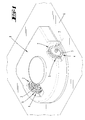
- An automatically movable ground dust collecting device 1 which has two wheels 2 in the embodiment. One or both of the wheels 2 may be driven.
- Such an impeller 2 including the following FIGS. 2 to 8 More specifically, a hub 3 and a tire 4 are provided.
- the tire 4 forms on its circumference a tire contact patch 5.
- the tire contact patch 5 designates the part of the tire 4 which comes into contact with a base 6 in the course of one revolution of the wheel during normal use, if necessary in addition to the usual load of excessive load.
- an impeller 2 Central to the hub 3, an impeller 2 further on a real or geometric axis of rotation 7.
- the tire contact surface 5 transitions radially inwards, viewed in the direction of the axis of rotation 7, into two opposite side surfaces 8. As usual for tires, this is made of an elastic material. It may be, for example to act rubber, a rubber compound or a thermoplastic elastomer.
- the tire contact surface 5 is at least partially formed by tread blocks 9.
- the tread blocks 9 are provided one behind the other in a circumferential direction U of the tire 4.
- the tire contact patch only by the tread blocks 9, according to their radially outer faces, given.
- the formed by a tread block 9 part of the tire footprint 5 has in cross section, see FIG. 4 , a sloping towards the center of the tire 4 profile.
- the center of the tire 4 is given in this respect by a plane perpendicular to the axis of rotation 7 extending plane E, centered on a maximum width b of the tire, as shown in the cross section according to FIG. 4 results, runs.
- At the junction of the part of the tire contact surface 5 forming portion of a profile block 9 in a side surface 8 of this profile block 9 forms radially, in a radius direction r starting from the axis of rotation 7, and in the direction of Turning axis 7, a furthest projecting portion of the tire footprint 5.
- a free-projecting corner profile 10 is formed by such a profile block 9.
- opposing tread blocks 9 are formed in the tire 4.
- only one profile block 9 is formed on both sides of the center M, in a cross-sectional view.
- a displaced dimension v corresponds to a length of a profile block 9 considered in this direction. However, it may also be smaller, corresponding to only about one tenth to nine tenths of this length of the profile block 9.
- a tread block 9 preferably also extends in this cross-section from the respective side face 8 to the middle M.
- a freestanding height h of a tread block 9 which is equal to the distance from one in the circumferential direction U between two with respect to the center M, d. H. in particular on the same side of the center located tread blocks 9 lowered intermediate surface F up to the respective point of the tire contact surface 5 in the unloaded state corresponds, based on the profile corner 10 preferably one tenth to nine tenths, more preferably about two to four tenths of the width b of Tire 4.
- a profile block 9 can in particular continue in a plan view, see FIG. 3 , have a rectangular cross-section.
- the cross section is also, at least approximately, square.
- a side surface 8 of the tire 4 has two areas to be distinguished from each other.
- a circumferential plane which is formed by the intermediate surface F, initially results in a circumferentially unimpeded continuous in a side view surface band.
- a side surface 8 is in each case formed by a profile block 9, so that crenellated paragraphs result.
- a side surface 8 is preferably formed substantially straight.
- the hub 3 is preferably only in contact with a smaller surface portion of the tire 4 relative to the width b. This in any case based on an unloaded condition. As it turned out FIG. 4 For example, yields, related to the hub 3 immediately facing width b 1 of the tire 4 contacts with the hub 3 in the width direction only approximately one to three tenths of the width B1. Prefers is in any case that the contact is given only to about one to three quarters of the width b 1 so far.
- the tire 4 for mounting on the hub 3 preferably on the hub side on a radially inwardly projecting Garrungsausformung 15.
- This Halterausformung is formed in a further preferred embodiment as a circumferentially U extending rib.
- the Halterausausformung 15 may be provided with interruptions.
- the Halterausformung 15 is formed to extend radially inwardly projecting.
- a support receptacle is formed. This is preferably formed by two circumferential, also rib-like projections 16.
- the rib-like projections 16 define therebetween a groove which may correspond in dimension to the free dimension of a support formation 15.
- the projections 16 may be interrupted in the circumferential direction formed.
- a projection 16 alternately with respect to the side surfaces the Garrungsausformung 15 may be provided over the circumference seen, so that in a certain cross-section, with the exception of any overlap in the circumferential direction always only one projection 16 is formed.
- FIGS. 7 and 8 When driving on a stepped obstacle H with a small relative to the impeller 2 edge radius comes in the in the FIGS. 7 and 8 shown constellation only one tread block 9 in engagement with the edge K of the obstacle H. Due to the softness of the tread block 9 this is squeezed radially inward, as is apparent from FIG. 8 results.
- the edge K moves into the space between two tread blocks 9, approximately up to the surface F. This results in a sense a Vernierungssituation the tire 4 with respect to the edge K.
- a pointing in the circumferential direction U end face 17 of a profile block 9 engages over the edge K over.
Landscapes
- Engineering & Computer Science (AREA)
- Mechanical Engineering (AREA)
- Tires In General (AREA)
- Electric Vacuum Cleaner (AREA)
- Vehicle Cleaning, Maintenance, Repair, Refitting, And Outriggers (AREA)
Abstract
Description
- Die Erfindung betrifft zunächst ein selbsttätig verfahrbares Bodenstaub-Aufsammelgerät mit mindestens einem angetriebenen Laufrad, wobei das Laufrad eine Drehachse, eine Nabe und einen eine Reifenaufstandsfläche ausbildenden Reifen aufweist, wobei weiter die Reifenaufstandsfläche nach radial innen in zwei gegenüberliegende Seitenflächen übergeht und der aus elastischem Material bestehende Reifen jeweils einen Teil der Reifenaufstandsfläche bildende Profilblöcke aufweist, die in Umfangsrichtung hintereinander vorgesehen sind.
- Die Erfindung betrifft im Weiteren ein Laufrad, das eine Drehachse, eine Nabe und einen eine Reifenaufstandsfläche ausbildenden Reifen aufweist, wobei die Reifenaufstandsfläche nach radial innen in zwei gegenüberliegende Seitenflächen übergeht und der aus elastischem Material bestehende Reifen jeweils einen Teil der Reifenaufstandsfläche bildende Profilblöcke aufweist, die in Umfangsrichtung hintereinander vorgesehen sind.
- Derartige selbsttätig verfahrbare Bodenstaub-Aufsammelgeräte bzw. Laufräder sind bereits in vielfacher Hinsicht bekannt geworden. Es wird beispielsweise auf die
DE 10 2008 009 617 A1 und dieUS 6,633,150 B1 verwiesen. - Die Erfindung beschäftigt sich mit der Aufgabenstellung, ein selbsttätig verfahrbares Bodenstaub-Aufsammelgerät bzw. ein Laufrad anzugeben, bei welchem insbesondere im Hinblick auf eine Überwindung von Hindernissen eine günstige Gestaltung gefunden ist.
- Eine mögliche Lösung der Aufgabe ist nach einem ersten Erfindungsgedanken bei einem selbsttätig verfahrbaren Bodenstaub-Aufsammelgerät gegeben, bei welchem ein Profilblock zugleich einen Teil einer zugeordneten Seitenfläche bildet, der durch den Profilblock gebildete Teil der Reifenaufstandsfläche ausgehend von einem Übergang zu der Seitenfläche im Querschnitt ein zur gegenüberliegenden Seitenfläche hin abfallendes Profil aufweist und der Profilblock an diesem Übergang radial und in Richtung der Drehachse einen am weitesten vorstehenden Bereich der Reifenaufstandsfläche des Reifens bildet.
- Desgleichen ist eine mögliche Lösung der Aufgabe bei einem Laufrad gegeben, das mit den vorstehend aufgeführten Merkmalen ausgebildet ist.
- Dadurch, dass der Profilblock einen Teil der Reifenaufstandsfläche bildet und im Querschnitt zu der gegenüberliegenden Seitenfläche hin abfällt, ergibt sich ein der Seitenfläche zugeordneter Vorstandsbereich des Profilsblocks, der aufgrund des bei einem Profilblock gegebenen Freistands beim Zusammenwirken mit einem Hindernis wie etwa einer Kante oder Stufe, wenn eine Belastung auf den Profilblock im Wesentlichen in Umfangsrichtung des Reifens erfolgt, eine günstige Verkrallung ermöglicht. Dadurch, dass das Material des Reifens elastisch ist, ergibt sich bei Kontakt eines solchen Profilblocks mit dem Boden aufgrund der üblicherweise wirkenden Last eine Abflachung des Profils und damit eine größere Aufsetzfläche auf den Boden. Dies zugleich ausgehend von dem radial und in Richtung der Drehachse am weitesten vorstehenden Bereich des Reifens, was günstig zur Stabilität des Fahrens insgesamt beitragen kann.
- Weitere Merkmale der Erfindung sind nachstehend, auch in der Figurenbeschreibung und der Zeichnung, oftmals in Ihrer bevorzugten Zuordnung zu dem bereits vorstehend erläuterten Konzept beschrieben bzw. dargestellt, sie können aber auch in einer Zuordnung zu nur einem oder mehreren einzelnen Merkmalen, die hier beschrieben oder zeichnerisch dargestellt sind, oder unabhängig oder in einem anderen Gesamtkonzept, von Bedeutung sein.
- So ist es bevorzugt, dass bezogen auf eine in Richtung der Drehachse gegebene Mitte der Reifenaufstandsfläche der durch den Profilblock gebildete Teil der Reifenaufstandsfläche bis zu der Mitte hin abfällt. Ein - einzelner - Profilblock bildet somit bezogen auf den Querschnitt etwa hälftig die Reifenaufstandsfläche. Dadurch, dass der Abfall bis hin zu der Mitte gegeben ist, ist ein entsprechend variabler Vergrößerungsbereich der tatsächlich mit einem Boden in Berührung stehenden Abschnitte der Reifenaufstandsfläche gegeben. Bevorzugt ist hierbei, dass zufolge der Elastizität des Materials bei einem üblichen Gewicht des Gerätes, an welchem sich das Laufrad befindet, praktisch, jedenfalls bezogen auf den genannten Querschnitt, der gesamte durch einen solchen Profilblock gebildete Teil der Reifenaufstandsfläche auch auf dem Boden aufliegt.
- In weiterer Einzelheit ist bevorzugt, dass bezogen auf die genannte Mitte gegenüberliegende Profilblöcke ausgebildet sind. Diese gegenüberliegenden Profilblöcke sind weiter bevorzugt untereinander gleichgestaltet. Insbesondere weisen sie bevorzugt eine gleiche Grundfläche auf. Auch ist darüber hinaus bevorzugt, dass ihre Kontur und/oder ihre Erstreckung in Richtung der Drehachse und/oder in radialer Richtung bezogen auf die Drehachse jeweils gleich sind.
- Diese gegenüberliegenden Profilblöcke können in weiterer Einzelheit in Umfangsrichtung versetzt zueinander angeordnet sein. Hierbei kann zunächst eine überlappende Anordnung vorgesehen sein, so dass in einer Seitenansicht, gesehen in Richtung der Drehachse des Rades, einer der beiden Profilblöcke durch den anderen teilweise überdeckt ist. Das Überdeckungsmaß in Umfangsrichtung kann hierbei beispielsweise einem Zehntel bis zwei Drittel der Erstreckung eines Profilblocks in Umfangsrichtung entsprechen. Bevorzugt ist jedoch insoweit, dass die gegenüberliegenden Profilblöcke in Umfangsrichtung derart versetzt sind, dass in der genannten Seitenansicht praktisch beide Profilblöcke sich vollständig mit ihrer diesbezüglichen Fläche abbilden.
- Aufgrund der Formung des Reifens aus einem elastischen Material wie etwa einer Gummimischung oder einem thermoplastischem Elastomer und den diesbezüglichen Formungsvorgängen sind geringfügige Maßungenauigkeiten immer gegeben.
- Weiter ist bevorzugt, dass ein Profilblock sich im Querschnitt von der jeweiligen Seitenfläche bis zu der Mitte erstreckt. Die Hälfte des Profils wird in dieser Hinsicht, bevorzugt jeweils, von einem Profilblock eingenommen. Zwei gegenüberliegende Profilblöcke bilden gemeinsam im Querschnitt entsprechend die Profillinie. Hierbei ist bevorzugt keine oder praktisch nur eine singuläre Querschnittsfläche gegeben, aufgrund der Versetzung der Profilblöcke in Umfangsrichtung zueinander, in welcher beide gegenüberliegenden Profilblöcke gleichzeitig als Schnittfläche wiedergegeben sind.
- Es ist auch bevorzugt, dass ein Profilblock in der Draufsicht einen rechteckigen Grundriss aufweist. Hierbei kann auch eine Gestaltung mit gleichlangen Seiten gegeben sein, also eine in der Draufsicht quadratische Ausbildung eines Profilblocks.
- Hinsichtlich einer Seitenfläche ist bevorzugt, dass sie im Querschnitt im Wesentlichen gerade verlaufend ausgebildet ist. Sie verläuft auch ausgehend von dem Übergang in die Reifenaufstandsfläche bevorzugt zu der genannten Mitte hin zulaufend, so dass sich im Querschnitt gesehen von der Drehachse eine nach außen konisch öffnende Kontur des Reifens ergibt. In den Bereichen, in denen jeweils in Umfangsrichtung kein Profilblock ausgebildet ist, ist die Gestaltung bevorzugt derart vorgesehen, dass sich bezogen auf den genannten Querschnitt eine bevorzugt bis zur Mitte reichende Stufenfläche ergibt. Die Stufenfläche ist auch bevorzugt etwa gleichgerichtet zu der Drehachse verlaufend in dem Querschnitt gegeben. Die Vertikalfläche der Stufe ergibt sich entsprechend bevorzugt in der genannten Mitte. Die Vertikalfläche geht bevorzugt radial außen unmittelbar in die durch einen Profilblock gebildete Reifenaufstandsfläche über. Die Absenkung der Stufenfläche gegenüber dem größten Absenkmaß eines Profilblocks ausgehend von dem radial und in Richtung der Drehachse am weitesten vorstehenden Bereich ergibt sich etwa um die Hälfte bis zum Dreifachen dieses Maßes.
- Weiter ist bevorzugt, dass ein Profilblock bzw. ein diesbezüglicher Reifenabschnitt, ausgehend von der Seitenfläche unterseitig, der Nabe zugewandt einen Erstreckungsabschnitt aufweist, der einen Freistand zu einem zugeordneten Schulterabschnitt der Nabe aufweist. Dieser Freistand ermöglicht bei entsprechender Belastung ein elastisches Verformen des zugeordneten Reifenabschnitts insgesamt nach radial innen. Dies begünstigt die angesprochene Ausbildung einer größeren Aufstandsfläche wenn im üblichen Verfahrmodus ein entsprechender Abschnitt des Reifens zur Auflage auf den Boden kommt.
- Insbesondere ist bevorzugt die Elastizität des Materials so gewählt, dass im Belastungszustand, bei dem genannten üblichen Verfahren bzw. der Auflage der Reifenaufstandsfläche auf den Boden unter Tragen der diesbezüglichen Last des Gerätes, der Erstreckungsabschnitt durch den Schulterabschnitt eine Abstützung erfährt. Der Erstreckungsabschnitt kommt zur Auflage auf der Abstützung. Hierbei kann vorgesehen sein, dass die Ausbildung so getroffen ist, dass der Erstreckungsabschnitt nahezu vollständig zur Auflage kommt. Er kann aber auch bezogen auf eine Abmessung des Erstreckungsabschnittes in Richtung der Drehachse auf einem Zehntel bis etwa acht Zehntel der Abmessung zur Auflage kommen.
- Eine Erstreckung des Reifens in Richtung der Drehachse im Bereich der Profilblöcke, insbesondere also ausgehend von einem Erstreckungsabschnitt nach radial außen, beträgt bevorzugt das Zweifache der diesbezüglichen Erstreckung eines Profilblocks. Der Profilblock wächst entsprechend in radialer Richtung etwa bei halbem radialen Maß des Reifens aus diesem im gegebenen Freistand heraus.
- Weiter ist bevorzugt, dass der Reifen nabenseitig eine nach radial innen vorstehende Halterungsausformung aufweist. Darüber hinaus bevorzugt ist der Reifen außerhalb eines Zustandes, in welchem ein Erstreckungsabschnitt eine Abstützung auf einem Schulterabschnitt erfährt, auch praktisch nur durch diese Halterungsausformung abgestützt.
- Eine Halterungsausformung kann als in Umfangsrichtung verlaufende Rippe ausgebildet sein. Hierbei kann sie in Umfangsrichtung durchgehend oder abschnittsweise vorgesehen sein. Die Halterungsausformung verläuft auch bevorzugt in Radialrichtung, bezogen auf den unbelasteten Zustand, vorstehend gegenüber einem Erstreckungsabschnitt.
- Die Halterungsausformung ist weiter bevorzugt in einer durch zwei umlaufende, in Richtung der Drehachse beabstandete Rippen der Nabe gebildete Nut aufgenommen. Die Stirnflächen dieser Rippen können auch noch zur Abstützung des Reifens beitragen, wobei diese Stirnfläche gegebenenfalls an einem diesbezüglichen, vergleichsweise kleinen, Abschnitt einer Erstreckungsfläche anliegen können.
- Die vor- und nachstehend angegebenen Bereiche bzw. Wertebereiche oder Mehrfachbereiche schließen hinsichtlich der Offenbarung auch sämtliche Zwischenwerte ein, insbesondere in Ein-Zehntel-Schritten der jeweiligen Dimension, gegebenenfalls also auch dimensionslos, also beispielsweise ein Zehntel einer Länge, Breite etc. oder eines X-fachen. Wenn beispielsweise auf ein Viertel bis drei Viertel einer Länge, Breite oder dergleichen eines anderen Teils Bezug genommen ist, ist desgleichen in die Offenbarung eingeschlossen ein Bereich von 0,275 bis 0,75 oder 0,275 bis 0,725 oder 0,25 bis 0,75 oder 0,3 bis 0,75 etc. Diese Offenbarung dient einerseits zur Eingrenzung der genannten Bereichsgrenzen von unten und/oder oben, wie auch beispielhaft dargelegt, alternativ oder ergänzend aber auch zur Offenbarung eines oder mehrere singulärer Werte aus einem jeweilig angegebenen Bereich.
- Nachstehend ist die Erfindung weiter anhand der beigefügten Zeichnung erläutert, die aber lediglich ein Ausführungsbeispiel darstellt. Hierbei zeigt:
- Fig. 1
- eine teilweise, im Bereich der Laufräder, aufgebrochene Darstellung eines beispielhaften Boden-Aufsammelgerätes;
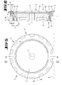
- Fig. 2
- eine perspektivische Ansicht eines Laufrades;
- Fig. 3
- eine Draufsicht auf das Laufrad gemäß
Figur 2 ; - Fig. 4
- einen Querschnitt entlang der Linie IV - IV in
Figur 2 ; - Fig. 5
- eine Seitenansicht des Laufrades im belasteten Zustand;
- Fig. 6
- einen Querschnitt durch den Gegenstand gemäß
Figur 5 , geschnitten entlang der Linie VI - VI; - Fig. 7
- der Gegenstand gemäß
Figur 5 in Zusammenwirkung mit einem stufenförmigen Hindernis; und - Fig. 8
- einen Querschnitt durch den Gegenstand gemäß
Figur 7 , geschnitten entlang der Linie VIII - VIII. - Dargestellt und beschrieben ist, mit Bezug zu
Figur 1 , ein selbsttätig verfahrbares Bodenstaub-Aufsammelgerät 1, das beim Ausführungsbeispiel über zwei Laufräder 2 verfügt. Eines oder beide der Laufräder 2 können angetrieben sein. - Ein derartiges Laufrad 2, wozu auf die folgenden
Figuren 2 bis 8 Bezug genommen ist, weist im Einzelnen eine Nabe 3 und einen Reifen 4 auf. Der Reifen 4 bildet an seinem Umfang eine Reifenaufstandsfläche 5. Die Reifenaufstandsfläche 5 bezeichnet den Teil des Reifens 4, der im Zuge einer Radumdrehung bei üblicher Benutzung, gegebenenfalls ergänzend auch bei die übliche Belastung übersteigender Belastung, mit einem Boden 6 in Berührung kommt. Zentral zu der Nabe 3 weist ein Laufrad 2 weiter eine reale oder geometrische Drehachse 7 auf. - Die Reifenaufstandsfläche 5 geht nach radial innen, gesehen in Richtung der Drehachse 7 in zwei gegenüberliegende Seitenflächen 8 über. Wie für Reifen üblich, besteht dieser aus einem elastischen Material. Es kann sich beispielsweise um Gummi, eine Gummimischung oder ein thermoplastisches Elastomer handeln. Die Reifenaufstandsfläche 5 ist zumindest teilweise durch Profilblöcke 9 gebildet. Die Profilblöcke 9 sind in einer Umfangsrichtung U des Reifens 4 hintereinander vorgesehen. Bei dem dargestellten Ausführungsbeispiel und bevorzugt ist bei üblicher Fahrbeanspruchung und ohne den Sonderfall einer Zusammenwirkung des Reifens mit einem Hindernis die Reifenaufstandsfläche nur durch die Profilblöcke 9, entsprechend deren radial äußere Stirnflächen, gegeben. Die Profilblöcke 9 bilden zusammen mit weiteren in Radialrichtung weisenden Flächen des Reifens, bei dem dargestellten Ausführungsbeispiel sind dies die nachstehend noch beschriebenen Zwischenflächen F, eine Reifenumfangsfläche. Zumindest theoretisch kann praktisch jeder Bereich der Reifenumfangsfläche mit einem Boden bzw. einem Hindernis in Kontakt kommen und so auch Bereiche außerhalb der Stirnflächen der Profilblöcke 9 zumindest temporär Teil der Reifenaufstandsfläche 5 werden.
- Der durch einen Profilblock 9 gebildete Teil der Reifenaufstandsfläche 5 weist im Querschnitt, siehe etwa
Figur 4 , ein zur Mitte des Reifens 4 abfallendes Profil auf. Die Mitte des Reifens 4 ist in dieser Hinsicht durch eine senkrecht zur Drehachse 7 verlaufende Ebene E gegeben, die mittig bezogen auf eine größte Breite b des Reifens, wie sie sich in dem Querschnitt gemäßFigur 4 ergibt, verläuft. Ein Profilblock 9 bildet zugleich einen Teil einer zugeordneten Seitenfläche 8. An dem Übergang des einen Teil der Reifenaufstandsfläche 5 bildenden Bereiches eines Profilblockes 9 in eine Seitenfläche 8 bildet dieser Profilblock 9 radial, in einer Radiusrichtung r ausgehend von der Drehachse 7, und in Richtung der Drehachse 7, einen am weitesten vorstehenden Bereich der Reifenaufstandsfläche 5. Konkreter betrachtet ist eine freikragende Profilecke 10 durch einen solchen Profilblock 9 gebildet. - Bezogen auf die genannte Mitte M sind in dem Reifen 4 gegenüberliegende Profilblöcke 9 ausgebildet. Insbesondere und bevorzugt sind auch auf beiden Seiten der Mitte M, in einer Querschnittsbetrachtung, nur jeweils ein Profilblock 9 ausgebildet.
- Diese gegenüberliegenden Profilblöcke 9, unabhängig davon, ob jeweils nur einer ausgebildet ist, sind weiter bevorzugt in Umfangsrichtung U des Reifens 4 versetzt zueinander angeordnet. Ein Versetztmaß v, betrachtet in Umfangsrichtung U, entspricht beim Ausführungsbeispiel einer in dieser Richtung betrachteten Länge eines Profilblockes 9. Es kann aber auch kleiner sein, etwa nur einem Zehntel bis neun Zehntel dieser Länge des Profilblockes 9 entsprechen. Bezogen insbesondere auf eine Ausführungsform, bei welcher ausgehend von der Mitte in Bezug auf eine Querschnittsbetrachtung gegenüberliegend nur zwei Profilblöcke 9 vorgesehen sind, erstreckt sich ein Profilblock 9 auch bevorzugt in diesem Querschnitt von der jeweiligen Seitenfläche 8 bis zu der Mitte M.
- Eine freistehende Höhe h eines Profilblockes 9, welche dem Abstand von einer in Umfangsrichtung U zwischen zwei bezogen auf die Mitte M gleichen, d. h. insbesondere auf derselben Seite der Mitte befindlichen Profilblöcke 9 abgesenkten Zwischenfläche F bis hin zu dem jeweiligen Punkt der Reifenaufstandsfläche 5 im unbelasteten Zustand entspricht, entspricht bezogen auf die Profilecke 10 bevorzugt einem Zehntel bis neun Zehntel, weiter bevorzugt etwa zwei bis vier Zehntel der Breite b des Reifens 4.
- Ein Profilblock 9 kann insbesondere weiter in einer Draufsicht, siehe etwa
Figur 3 , einen rechteckigen Querschnitt aufweisen. Bevorzugt ist der Querschnitt auch, zumindest annähernd, quadratisch. - Das Profil P der Reifenaufstandsfläche 5 weist ausgehend von einem Übergang in eine Seitenfläche 8, vergleiche auch hierzu etwa wieder
Figur 6 , zunächst eine bevorzugt gerade oder nur mit einem geringen Abfall zur Mitte M, gegebenenfalls auch leicht ansteigend zu der Mitte M verlaufenden Außenabschnitt 11 auf. Der Außenabschnitt 11 geht dann in einen Anschlussabschnitt 12 über, der, bevorzugt im Sinne einer Geraden, zu der Mitte M hin abfällt. Ausgehend von der Mitte M ergibt sich daher nach außen hin eine Überhöhung u des Profils P, die etwa einem Viertel bis drei Viertel, bevorzugt ca. ein Drittel, der Höhe h eines Profilblocks im Bereich der Profilecke 10 entspricht.
Eine Seitenfläche 8 des Reifens 4 weist zwei voneinander zu unterscheidende Bereiche auf. Ausgehend von radial innen, von einem Beginn (hier gegeben durch den weiter unten erläuterten Erstreckungsabschnitt 13) des Reifens 4, bis zu einer Umfangsebene, welche durch die Zwischenfläche F gebildet ist, ergibt sich zunächst ein in einer Seitenansicht umfangsmäßig unbeeinflusst durchlaufendes Flächenband. Darüber hinaus in Umfangsrichtung ist eine Seitenfläche 8 jeweils durch einen Profilblock 9 geformt, so dass sich zinnenartige Absätze ergeben. - Bezogen auf einen Querschnitt ist eine Seitenfläche 8 bevorzugt im Wesentlichen gerade verlaufend ausgebildet.
- Die Nabe 3 ist bezogen auf die Breite b bevorzugt nur mit einem kleineren Flächenanteil des Reifens 4 in Kontakt. Dies jedenfalls bezogen auf einen unbelasteten Zustand. Wie sich aus
Figur 4 beispielsweise ergibt, ist bezogen auf die der Nabe 3 unmittelbar zugewandte Breite b1 des Reifens 4 der Kontakte zu der Nabe 3 in Breitenrichtung nur etwa ein bis drei Zehntel der Breite b1. Bevorzugt ist jedenfalls, dass der Kontakt nur auf etwa ein bis drei Viertel der Breite b1 insoweit gegeben ist. - Hierdurch ergeben sich ein- oder beidseitig, bezogen auf die Mitte M, ein Erstreckungsabschnitt 13 des Reifens 4, der zu einem zugeordneten Schulterabschnitt 14 der Nabe 3 einen Freistand f aufweist. Dieser Freistand f ergibt sich in Richtung der Drehachse gesehen und bezogen auf einen Querschnitt, wie er in
Figur 4 beispielsweise auch wiedergegeben ist. - Bevorzugt ist die Größe des Freistandes f, also das freie radiale Maß, das sich hierdurch zwischen dem Schulterabschnitt 14 und dem Erstreckungsabschnitt 13 des Laufrades ergibt, so gewählt, dass bei einem üblichen Verfahren des Gerätes, der Erstreckungsabschnitt durch den Schulterabschnitt eine Abstützung erfährt. Dies ist beispielsweise in
Figur 6 , unten, zu erkennen. - In weiterer Einzelheit weist der Reifen 4 zur Halterung an der Nabe 3 bevorzugt nabenseitig eine nach radial innen vorstehende Halterungsausformung 15 auf. Diese Halterungsausformung ist in weiterer bevorzugter Ausführungsform als eine in Umfangsrichtung U sich erstreckende Rippe ausgebildet. Hierbei kann die Halterungsausformung 15 mit Unterbrechungen vorgesehen sein. Gegenüber dem Erstreckungsabschnitt 13 ist die Halterungsausformung 15 nach radial innen vorstehend verlaufend geformt. An der Nabe 3 ist diesbezüglich eine Halterungsaufnahme ausgebildet. Bevorzugt ist diese durch zwei umlaufende, ebenfalls rippenartige Vorsprünge 16 gebildet. Die rippenartigen Vorsprünge 16 bilden zwischen sich eine Nut aus, die in ihrer Abmessung der freien Abmessung einer Halterungsausformung 15 entsprechen kann. Auch die Vorsprünge 16 können in Umfangsrichtung unterbrochen verlaufend ausgebildet sein. Auch kann ein Vorsprung 16 abwechselnd bezogen auf die Seitenflächen der Halterungsausformung 15 über den Umfang gesehen vorgesehen sein, so dass in einem bestimmten Querschnitt, mit Ausnahme einer etwaigen Überlappung in Umfangsrichtung immer nur ein Vorsprung 16 sich abbildet.
- Bezogen auf den Gegenstand eines Laufrades 2 als solches sind ersichtlich vorstehende Ausführungen in gleicher Weise von Bedeutung, nur dass hier die weiteren ein Bodenreinigungsgerät, insbesondere einen selbsttätig verfahrbares Bodenreinigungsgerät, betreffenden Merkmale nicht gegeben sind.
- Mit Bezug zu den
Figuren 7 und 8 ist die Wirkungsweise des Laufrades 2 weiter erläutert. - Bei einem Auffahren auf ein stufenartiges Hindernis H mit einem im Verhältnis zu dem Laufrad 2 kleinen Kantenradius kommt bei der in den
Figuren 7 und 8 dargestellten Konstellation nur ein Profilblock 9 in Eingriff mit der Kante K des Hindernisses H. Aufgrund der Weichheit des Profilblockes 9 wird dieser nach radial innen gequetscht, wie sich dies ausFigur 8 ergibt. Die Kante K fährt in den Zwischenraum zwischen zwei Profilblöcken 9 ein, etwa bis auf die Fläche F. Hierdurch ergibt sich gleichsam eine Verzahnungssituation des Reifen 4 in Bezug auf die Kante K. Eine in Umfangsrichtung U weisende Stirnfläche 17 eines Profilblockes 9 greift über die Kante K über. Da in Umfangsrichtung U die Beanspruchung unterschiedlich ist zu einer zentral nach radial innen wirkenden Beanspruchung, kommt hier die Weichheit bzw. Elastizität des Materials nicht in gleicher Weise zur Wirkung. Es ergibt sich entsprechend gleichsam ein Verzahnungseingriff, der es dem Laufrad 2 ermöglicht, sich an der Kante K zu verkrallen und so das Bodenstaub-Aufsammelgerät 1, an welchem das Laufrad 2 gegebenenfalls angebracht ist, insgesamt anzuheben. Darüber hinaus kann es zu einem Auswölben des Reifens und insbesondere des betroffenen Profilblockes 9 bezogen auf die Seitenfläche 8 insbesondere des betroffenen Profilblockes 9 kommen, wie auch inFigur 8 dargestellt. Eine gewisse Auswölbung in dieser Hinsicht ergibt sich auch bei üblichem Fahrbetrieb, sieheFigur 6 . - Alle offenbarten Merkmale sind (für sich) erfindungswesentlich. In die Offenbarung der Anmeldung wird hiermit auch der Offenbarungsinhalt der zugehörigen/beigefügten Prioritätsunterlagen (Abschrift der Voranmeldung) vollinhaltlich mit einbezogen, auch zu dem Zweck, Merkmale dieser Unterlagen in Ansprüche vorliegender Anmeldung mit aufzunehmen. Die Unteransprüche charakterisieren in ihrer fakultativ nebengeordneten Fassung eigenständige erfinderische Weiterbildungen des Standes der Technik, insbesondere um auf Basis dieser Ansprüche Teilanmeldungen vorzunehmen.
-
- 1
- Bodenstaub-Aufsammelgerät
- 2
- Laufrad
- 3
- Nabe
- 4
- Reifen
- 5
- Reifenaufstandsfläche
- 6
- Boden
- 7
- Drehachse
- 8
- Seitenfläche
- 9
- Profilblock
- 10
- Profilecke
- 11
- Außenabschnitt
- 12
- Anschlussabschnitt
- 13
- Erstreckungsabschnitt
- 14
- Schulterabschnitt
- 15
- Halterungsausformung
- 16
- Vorsprung
- 17
- Stirnfläche
- b
- Breite
- b1
- Breite
- E
- Ebene
- F
- Fläche
- f
- Freistand
- F
- Zwischenfläche
- H
- Hindernis
- h
- Höhe
- K
- Kante
- M
- Mitte
- P
- Profil
- r
- Radiusrichtung
- U
- Umfangsrichtung
- u
- Überhöhung
- v
- Versetztmaß
Claims (10)
- Selbsttätig verfahrbares Bodenstaub-Aufsammelgerät (1) mit mindestens einem Laufrad (2), wobei das Laufrad (2) eine Drehachse (7), eine Nabe (3) und einen eine Reifenaufstandsfläche (5) ausbildenden Reifen (4) aufweist, wobei weiter die Reifenaufstandsfläche (5) nach radial innen in zwei gegenüberliegende Seitenflächen (8) übergeht und der aus elastischem Material bestehende Reifen (4) jeweils einen Teil der Reifenaufstandsfläche (5) bildende Profilblöcke (9) aufweist, die in Umfangsrichtung (U) hintereinander vorgesehen sind, dadurch gekennzeichnet, dass der durch einen Profilblock (9) gebildete Teil der Reifenaufstandsfläche (5) im Querschnitt ein zur Mitte (M) hin abfallendes Profil (P) aufweist, dass dieser Profilblock (9) zugleich einen Teil einer zugeordneten Seitenfläche (8) bildet und an diesem Übergang radial und in Richtung der Drehachse (7) einen am weitesten vorstehenden Bereich der Reifenaufstandsfläche (5) des Reifens (4) bildet.
- Bodenstaub-Aufsammelgerät (1) nach Anspruch 1 oder insbesondere danach, dadurch gekennzeichnet, dass bezogen auf eine in Richtung der Drehachse (7) gegebene Mitte (M) des Reifens (4) gegenüberliegende Profilblöcke (9) ausgebildet sind, wobei, bevorzugt, die gegenüberliegenden Profilblöcke (9) in Umfangsrichtung (U) versetzt zueinander angeordnet sind, wobei, weiter bevorzugt, ein Versetztmaß (v) einer Erstreckung eines Profilblocks (9) in Umfangsrichtung (U) entspricht.
- Bodenstaub-Aufsammelgerät (1) nach einem oder mehreren der vorhergehenden Ansprüche oder insbesondere danach, dadurch gekennzeichnet, dass ein Profilblock (9) sich im Querschnitt von der jeweiligen Seitenfläche (8) bis zur Mitte (M) erstreckt und/oder, dass ein Profilblock (9) in der Draufsicht einen rechteckigen Grundriss aufweist und/oder, dass eine Seitenfläche (8) im Querschnitt im Wesentlichen gerade verlaufend ausgebildet ist.
- Bodenstaub-Aufsammelgerät (1) nach einem oder mehreren der vorhergehenden Ansprüche oder insbesondere danach, dadurch gekennzeichnet, dass ein Profilblock (9) bzw. ein diesbezüglicher Reifenabschnitt in Richtung der Drehachse (7) und bezogen auf einen Querschnitt einen Erstreckungsabschnitt (12) aufweist, der einen Freistand (f) zu einem zugeordneten Schulterabschnitt (13) der Nabe (3) aufweist.
- Bodenstaub-Aufsammelgerät (1) nach einem oder mehreren der vorhergehenden Ansprüche oder insbesondere danach, dadurch gekennzeichnet, dass die Elastizität des Materials so gewählt ist, dass im Belastungszustand, wenn bei einem üblichen Verfahren des Gerätes der durch den Profilblock (9) gebildete Teil der Reifenaufstandsfläche (5) auf dem Boden (6) aufliegt, der Erstreckungsabschnitt (12) durch den Schulterabschnitt (13) eine Abstützung erfährt.
- Bodenstaub-Aufsammelgerät (1) nach einem oder mehreren der vorhergehenden Ansprüche oder insbesondere danach, dadurch gekennzeichnet, dass eine Erstreckung des Reifens (4) in Richtung der Drehachse (7) im Bereich der Profilblöcke (9) durch das Zweifache der diesbezüglichen Erstreckung eines Profilblocks (9) bestimmt ist.
- Bodenstaub-Aufsammelgerät (1) nach einem oder mehreren der vorhergehenden Ansprüche oder insbesondere danach, dadurch gekennzeichnet, dass der Reifen (4) nabenseitig eine nach radial innen vorstehende Halterungsausformung (14) aufweist, wobei, bevorzugt die Halterungsausformung (14) als in Umfangsrichtung (U) verlaufende Rippe ausgebildet ist.
- Bodenstaub-Aufsammelgerät (1) nach einem oder mehreren der vorhergehenden Ansprüche oder insbesondere danach, dadurch gekennzeichnet, dass eine Halterungsausformung (14) gegenüber einem Erstreckungsabschnitt (12) radial nach innen vorstehend verläuft.
- Bodenstaub-Aufsammelgerät (1) nach einem oder mehreren der vorhergehenden Ansprüche oder insbesondere danach, dadurch gekennzeichnet, dass an der Nabe (3) eine Halterungsaufnahme ausgebildet ist, die durch zwei umlaufende, in Richtung der Drehachse (7) beabstandete Vorsprünge (15) gebildete Nut bestimmt ist.
- Laufrad (2), insbesondere für ein Bodenstaub-Aufsammelgerät (1) nach einem der vorstehenden Ansprüche, mit einem oder mehreren Merkmalen der vorstehenden Ansprüche.
Applications Claiming Priority (1)
| Application Number | Priority Date | Filing Date | Title |
|---|---|---|---|
| DE102012108189.1A DE102012108189A1 (de) | 2012-09-04 | 2012-09-04 | Selbsttätig verfahrbares Bodenstaub-Aufsammelgerät und Laufrad, insbesondere für ein Bodenstaub-Aufsammelgerät |
Publications (3)
| Publication Number | Publication Date |
|---|---|
| EP2702915A2 true EP2702915A2 (de) | 2014-03-05 |
| EP2702915A3 EP2702915A3 (de) | 2017-12-27 |
| EP2702915B1 EP2702915B1 (de) | 2021-05-26 |
Family
ID=49123669
Family Applications (1)
| Application Number | Title | Priority Date | Filing Date |
|---|---|---|---|
| EP13182547.3A Active EP2702915B1 (de) | 2012-09-04 | 2013-09-02 | Selbsttätig verfahrbares Bodenstaub-Aufsammelgerät und Laufrad, insbesondere für ein Bodenstaub-Aufsammelgerät |
Country Status (6)
| Country | Link |
|---|---|
| US (1) | US9346325B2 (de) |
| EP (1) | EP2702915B1 (de) |
| JP (2) | JP6377893B2 (de) |
| CN (1) | CN103654643B (de) |
| DE (1) | DE102012108189A1 (de) |
| ES (1) | ES2873102T3 (de) |
Cited By (4)
| Publication number | Priority date | Publication date | Assignee | Title |
|---|---|---|---|---|
| CN105310606A (zh) * | 2014-08-01 | 2016-02-10 | 联润科技股份有限公司 | 清洁构件、装置及其清洁方法 |
| EP3000368A1 (de) * | 2014-09-23 | 2016-03-30 | LG Electronics Inc. | Roboterreiniger |
| EP3449789A1 (de) * | 2017-08-11 | 2019-03-06 | Vorwerk & Co. Interholding GmbH | Sich selbsttätig fortbewegendes bodenbearbeitungsgerät und rad für ein solches gerät |
| CN116409088A (zh) * | 2021-12-30 | 2023-07-11 | 苏州宝时得电动工具有限公司 | 移动设备 |
Families Citing this family (9)
| Publication number | Priority date | Publication date | Assignee | Title |
|---|---|---|---|---|
| KR102102228B1 (ko) * | 2013-12-18 | 2020-04-20 | 엘지전자 주식회사 | 자동 청소기 |
| CN106235973A (zh) * | 2016-01-25 | 2016-12-21 | 湖北泽森智能科技有限公司 | 一种扫地机器人的万向轮装置 |
| CN109567682B (zh) * | 2019-01-07 | 2023-09-12 | 云鲸智能科技(东莞)有限公司 | 一种应用于清洁机器人的轮胎和清洁机器人 |
| JP7280719B2 (ja) * | 2019-03-05 | 2023-05-24 | 東芝ライフスタイル株式会社 | 自律型掃除機 |
| DE102019130092B4 (de) * | 2019-11-07 | 2022-02-17 | Carl Freudenberg Kg | Rad und rädergeführtes Haushaltsgerät |
| DE102019131662A1 (de) * | 2019-11-22 | 2021-05-27 | Vorwerk & Co. Interholding Gmbh | Basisstation für ein Bodenbearbeitungsgerät, Antriebsrad für ein Bodenbearbeitungsgerät sowie System aus einer Basisstation und einem Bodenbearbeitungsgerät |
| CN216824306U (zh) | 2021-12-24 | 2022-06-28 | 深圳市东疆科技有限公司 | 一种鼻涕自动收集装置 |
| CN114451838B (zh) * | 2022-02-23 | 2023-04-28 | 深圳市无限动力发展有限公司 | 具有越障功能的滚轮及扫地机 |
| US12557952B2 (en) | 2022-10-17 | 2026-02-24 | Irobot Corporation | Asymmetric wheel for mobile cleaning robot |
Family Cites Families (24)
| Publication number | Priority date | Publication date | Assignee | Title |
|---|---|---|---|---|
| US1021816A (en) * | 1911-06-28 | 1912-04-02 | John Charles Barker | Outer cover for pneumatic tires. |
| US2180649A (en) * | 1938-07-20 | 1939-11-21 | David E White | Nonskid tire |
| JPS4614242Y1 (de) * | 1966-09-26 | 1971-05-20 | ||
| JPS5253618Y2 (de) * | 1972-02-09 | 1977-12-06 | ||
| JPS5338242Y2 (de) * | 1973-11-17 | 1978-09-16 | ||
| JPS5810241B2 (ja) * | 1975-03-04 | 1983-02-24 | 株式会社クボタ | カンシツチリヨウヨウタイヤ |
| JPS54303A (en) * | 1977-05-30 | 1979-01-05 | Iseki & Co Ltd | Agricultural superlow pressure flat tire |
| JPS5490702A (en) * | 1977-12-28 | 1979-07-18 | Bridgestone Corp | Tire with lug |
| JPS6116102A (ja) * | 1984-07-03 | 1986-01-24 | Sumitomo Rubber Ind Ltd | 二輪車用タイヤとリムの組立体 |
| JP3581789B2 (ja) * | 1998-06-11 | 2004-10-27 | 住友ゴム工業株式会社 | 農用車輪形走行装置および農用車輪 |
| US6633150B1 (en) | 2000-05-02 | 2003-10-14 | Personal Robotics, Inc. | Apparatus and method for improving traction for a mobile robot |
| US6431235B1 (en) * | 2000-05-11 | 2002-08-13 | Richard A. Steinke | Non-pneumatic tire and rim combination |
| JP4195968B2 (ja) * | 2002-06-14 | 2008-12-17 | パナソニック株式会社 | 自走式掃除機 |
| CN2696878Y (zh) * | 2004-03-24 | 2005-05-04 | 杨富翔 | 一种童车车轮 |
| KR100544480B1 (ko) * | 2004-05-12 | 2006-01-24 | 삼성광주전자 주식회사 | 로봇 청소기 |
| EP1721758A1 (de) * | 2005-05-13 | 2006-11-15 | JohnsonDiversey, Inc. | Gleitschutzrad |
| JP4807556B2 (ja) * | 2005-08-30 | 2011-11-02 | 国立大学法人東京工業大学 | タイヤ |
| DE202005019993U1 (de) * | 2005-12-20 | 2006-02-23 | Wessel-Werk Gmbh & Co. Kg | Selbstfahrende Saugreinigungsvorrichtung |
| US9108469B2 (en) * | 2007-10-01 | 2015-08-18 | Bridgestone Americas Tire Operations, Llc | Irrigation tire |
| DE102008009617B4 (de) | 2008-02-18 | 2023-06-07 | Vorwerk & Co. Interholding Gmbh | Bodenstaub-Aufsammelgerät mit mindestens einer angetriebenen Laufrolle, sowie Laufrolle, insbesondere für ein Bodenstaub-Aufsammelgerät |
| JP2010184686A (ja) * | 2009-02-13 | 2010-08-26 | Kaoru Yoneyama | タイヤ・リム組付体 |
| IT1394226B1 (it) * | 2009-04-02 | 2012-06-01 | F I R S R L | Ruota, in particolare per macchine semoventi quali carrelli o simili, e metodo di realizzazione della stessa. |
| TWM407846U (en) * | 2011-01-31 | 2011-07-21 | Micro Star Int Co Ltd | Transmission assembly and wheels thereof |
| US20130274861A1 (en) * | 2012-04-12 | 2013-10-17 | Sanford Health | Debranching Stent Graft Limb and Methods for Use |
-
2012
- 2012-09-04 DE DE102012108189.1A patent/DE102012108189A1/de not_active Withdrawn
-
2013
- 2013-08-29 JP JP2013178483A patent/JP6377893B2/ja not_active Expired - Fee Related
- 2013-09-02 ES ES13182547T patent/ES2873102T3/es active Active
- 2013-09-02 EP EP13182547.3A patent/EP2702915B1/de active Active
- 2013-09-03 US US14/016,299 patent/US9346325B2/en active Active
- 2013-09-04 CN CN201310553334.7A patent/CN103654643B/zh not_active Expired - Fee Related
-
2018
- 2018-05-22 JP JP2018097758A patent/JP6694470B2/ja not_active Expired - Fee Related
Non-Patent Citations (1)
| Title |
|---|
| None * |
Cited By (5)
| Publication number | Priority date | Publication date | Assignee | Title |
|---|---|---|---|---|
| CN105310606A (zh) * | 2014-08-01 | 2016-02-10 | 联润科技股份有限公司 | 清洁构件、装置及其清洁方法 |
| EP3000368A1 (de) * | 2014-09-23 | 2016-03-30 | LG Electronics Inc. | Roboterreiniger |
| US9615715B2 (en) | 2014-09-23 | 2017-04-11 | Lg Electronics Inc. | Robot cleaner |
| EP3449789A1 (de) * | 2017-08-11 | 2019-03-06 | Vorwerk & Co. Interholding GmbH | Sich selbsttätig fortbewegendes bodenbearbeitungsgerät und rad für ein solches gerät |
| CN116409088A (zh) * | 2021-12-30 | 2023-07-11 | 苏州宝时得电动工具有限公司 | 移动设备 |
Also Published As
| Publication number | Publication date |
|---|---|
| EP2702915B1 (de) | 2021-05-26 |
| ES2873102T3 (es) | 2021-11-03 |
| JP2014051275A (ja) | 2014-03-20 |
| CN103654643A (zh) | 2014-03-26 |
| JP6694470B2 (ja) | 2020-05-13 |
| CN103654643B (zh) | 2019-04-16 |
| DE102012108189A1 (de) | 2014-03-06 |
| US20140060716A1 (en) | 2014-03-06 |
| JP6377893B2 (ja) | 2018-08-22 |
| EP2702915A3 (de) | 2017-12-27 |
| US9346325B2 (en) | 2016-05-24 |
| JP2018167033A (ja) | 2018-11-01 |
Similar Documents
| Publication | Publication Date | Title |
|---|---|---|
| EP2702915A2 (de) | Selbsttätig verfahrbares Bodenstaub-Aufsammelgerät und Laufrad, insbesondere für ein Bodenstaub-Aufsammelgerät | |
| DE60022854T2 (de) | Reifenlauffläche mit unebenen nutenwänden | |
| DE69009657T2 (de) | Selbstreinigende Lauffläche. | |
| EP2728210B1 (de) | Kombination eines Bolzenteils mit einer Mutter | |
| EP2790930B1 (de) | Fahrzeugluftreifen für nutzfahrzeuge | |
| EP2643532B1 (de) | FUßBODENPANEEL MIT WEICHELASTISCHER NUTZSCHICHT | |
| DE2617691C2 (de) | Bedienungsorgan nach Art einer Fensterkurbel | |
| EP3449789B1 (de) | Sich selbsttätig fortbewegendes bodenbearbeitungsgerät und rad für ein solches gerät | |
| DE8524494U1 (de) | Luftreifen | |
| WO2018206175A1 (de) | Fahrzeugluftreifen | |
| WO2015185233A1 (de) | Fahrzeugluftreifen | |
| DE4018463A1 (de) | Hochleistungs-luftreifen | |
| WO2017102119A1 (de) | Fahrzeugluftreifen | |
| DE60017184T2 (de) | Reifenlaufflächenprofil für fahrzeuge mit hoher belastungsfähigkeit | |
| DE2163655C3 (de) | Luftreifen mit radialer Karkasse für schwere Fahrzeuge | |
| DE1605549B2 (de) | Tiefbettfelge für schlauchlose Reifen | |
| DE60030087T2 (de) | Fahrzeugreifen mit profil | |
| EP3303731B1 (de) | Gerüstbodenelement, insbesondere für ein baugerüst | |
| WO2014048635A1 (de) | Fahrzeugluftreifen | |
| EP3160775B1 (de) | Fahrzeugluftreifen | |
| DE202023107652U1 (de) | Autonome Betriebsvorrichtung | |
| DE202015106135U1 (de) | Faltkörbchen | |
| DE2803134A1 (de) | Bereifung fuer mehrfach bereifte fahrzeuge | |
| DE2921190C2 (de) | Blechschälbohrer, insbesondere zum Herstellen von Öffnungen in Karosserieteilen zur Hohlraumkonservierung | |
| EP2634015B1 (de) | Laufstreifenprofil eines Fahrzeugreifens |
Legal Events
| Date | Code | Title | Description |
|---|---|---|---|
| AK | Designated contracting states |
Kind code of ref document: A2 Designated state(s): AL AT BE BG CH CY CZ DE DK EE ES FI FR GB GR HR HU IE IS IT LI LT LU LV MC MK MT NL NO PL PT RO RS SE SI SK SM TR |
|
| AX | Request for extension of the european patent |
Extension state: BA ME |
|
| PUAI | Public reference made under article 153(3) epc to a published international application that has entered the european phase |
Free format text: ORIGINAL CODE: 0009012 |
|
| PUAL | Search report despatched |
Free format text: ORIGINAL CODE: 0009013 |
|
| AK | Designated contracting states |
Kind code of ref document: A3 Designated state(s): AL AT BE BG CH CY CZ DE DK EE ES FI FR GB GR HR HU IE IS IT LI LT LU LV MC MK MT NL NO PL PT RO RS SE SI SK SM TR |
|
| AX | Request for extension of the european patent |
Extension state: BA ME |
|
| RIC1 | Information provided on ipc code assigned before grant |
Ipc: A47L 9/00 20060101AFI20171121BHEP |
|
| STAA | Information on the status of an ep patent application or granted ep patent |
Free format text: STATUS: REQUEST FOR EXAMINATION WAS MADE |
|
| 17P | Request for examination filed |
Effective date: 20180604 |
|
| RBV | Designated contracting states (corrected) |
Designated state(s): AL AT BE BG CH CY CZ DE DK EE ES FI FR GB GR HR HU IE IS IT LI LT LU LV MC MK MT NL NO PL PT RO RS SE SI SK SM TR |
|
| STAA | Information on the status of an ep patent application or granted ep patent |
Free format text: STATUS: EXAMINATION IS IN PROGRESS |
|
| 17Q | First examination report despatched |
Effective date: 20200529 |
|
| GRAP | Despatch of communication of intention to grant a patent |
Free format text: ORIGINAL CODE: EPIDOSNIGR1 |
|
| STAA | Information on the status of an ep patent application or granted ep patent |
Free format text: STATUS: GRANT OF PATENT IS INTENDED |
|
| INTG | Intention to grant announced |
Effective date: 20201221 |
|
| GRAS | Grant fee paid |
Free format text: ORIGINAL CODE: EPIDOSNIGR3 |
|
| GRAA | (expected) grant |
Free format text: ORIGINAL CODE: 0009210 |
|
| STAA | Information on the status of an ep patent application or granted ep patent |
Free format text: STATUS: THE PATENT HAS BEEN GRANTED |
|
| AK | Designated contracting states |
Kind code of ref document: B1 Designated state(s): AL AT BE BG CH CY CZ DE DK EE ES FI FR GB GR HR HU IE IS IT LI LT LU LV MC MK MT NL NO PL PT RO RS SE SI SK SM TR |
|
| REG | Reference to a national code |
Ref country code: GB Ref legal event code: FG4D Free format text: NOT ENGLISH |
|
| REG | Reference to a national code |
Ref country code: CH Ref legal event code: EP |
|
| REG | Reference to a national code |
Ref country code: AT Ref legal event code: REF Ref document number: 1395360 Country of ref document: AT Kind code of ref document: T Effective date: 20210615 |
|
| REG | Reference to a national code |
Ref country code: DE Ref legal event code: R096 Ref document number: 502013015731 Country of ref document: DE |
|
| REG | Reference to a national code |
Ref country code: IE Ref legal event code: FG4D Free format text: LANGUAGE OF EP DOCUMENT: GERMAN |
|
| REG | Reference to a national code |
Ref country code: LT Ref legal event code: MG9D |
|
| PG25 | Lapsed in a contracting state [announced via postgrant information from national office to epo] |
Ref country code: BG Free format text: LAPSE BECAUSE OF FAILURE TO SUBMIT A TRANSLATION OF THE DESCRIPTION OR TO PAY THE FEE WITHIN THE PRESCRIBED TIME-LIMIT Effective date: 20210826 Ref country code: HR Free format text: LAPSE BECAUSE OF FAILURE TO SUBMIT A TRANSLATION OF THE DESCRIPTION OR TO PAY THE FEE WITHIN THE PRESCRIBED TIME-LIMIT Effective date: 20210526 Ref country code: FI Free format text: LAPSE BECAUSE OF FAILURE TO SUBMIT A TRANSLATION OF THE DESCRIPTION OR TO PAY THE FEE WITHIN THE PRESCRIBED TIME-LIMIT Effective date: 20210526 Ref country code: LT Free format text: LAPSE BECAUSE OF FAILURE TO SUBMIT A TRANSLATION OF THE DESCRIPTION OR TO PAY THE FEE WITHIN THE PRESCRIBED TIME-LIMIT Effective date: 20210526 |
|
| REG | Reference to a national code |
Ref country code: NL Ref legal event code: MP Effective date: 20210526 Ref country code: ES Ref legal event code: FG2A Ref document number: 2873102 Country of ref document: ES Kind code of ref document: T3 Effective date: 20211103 |
|
| PG25 | Lapsed in a contracting state [announced via postgrant information from national office to epo] |
Ref country code: SE Free format text: LAPSE BECAUSE OF FAILURE TO SUBMIT A TRANSLATION OF THE DESCRIPTION OR TO PAY THE FEE WITHIN THE PRESCRIBED TIME-LIMIT Effective date: 20210526 Ref country code: RS Free format text: LAPSE BECAUSE OF FAILURE TO SUBMIT A TRANSLATION OF THE DESCRIPTION OR TO PAY THE FEE WITHIN THE PRESCRIBED TIME-LIMIT Effective date: 20210526 Ref country code: GR Free format text: LAPSE BECAUSE OF FAILURE TO SUBMIT A TRANSLATION OF THE DESCRIPTION OR TO PAY THE FEE WITHIN THE PRESCRIBED TIME-LIMIT Effective date: 20210827 Ref country code: LV Free format text: LAPSE BECAUSE OF FAILURE TO SUBMIT A TRANSLATION OF THE DESCRIPTION OR TO PAY THE FEE WITHIN THE PRESCRIBED TIME-LIMIT Effective date: 20210526 Ref country code: IS Free format text: LAPSE BECAUSE OF FAILURE TO SUBMIT A TRANSLATION OF THE DESCRIPTION OR TO PAY THE FEE WITHIN THE PRESCRIBED TIME-LIMIT Effective date: 20210926 Ref country code: PT Free format text: LAPSE BECAUSE OF FAILURE TO SUBMIT A TRANSLATION OF THE DESCRIPTION OR TO PAY THE FEE WITHIN THE PRESCRIBED TIME-LIMIT Effective date: 20210927 Ref country code: PL Free format text: LAPSE BECAUSE OF FAILURE TO SUBMIT A TRANSLATION OF THE DESCRIPTION OR TO PAY THE FEE WITHIN THE PRESCRIBED TIME-LIMIT Effective date: 20210526 Ref country code: NO Free format text: LAPSE BECAUSE OF FAILURE TO SUBMIT A TRANSLATION OF THE DESCRIPTION OR TO PAY THE FEE WITHIN THE PRESCRIBED TIME-LIMIT Effective date: 20210826 |
|
| PG25 | Lapsed in a contracting state [announced via postgrant information from national office to epo] |
Ref country code: NL Free format text: LAPSE BECAUSE OF FAILURE TO SUBMIT A TRANSLATION OF THE DESCRIPTION OR TO PAY THE FEE WITHIN THE PRESCRIBED TIME-LIMIT Effective date: 20210526 |
|
| PG25 | Lapsed in a contracting state [announced via postgrant information from national office to epo] |
Ref country code: SM Free format text: LAPSE BECAUSE OF FAILURE TO SUBMIT A TRANSLATION OF THE DESCRIPTION OR TO PAY THE FEE WITHIN THE PRESCRIBED TIME-LIMIT Effective date: 20210526 Ref country code: SK Free format text: LAPSE BECAUSE OF FAILURE TO SUBMIT A TRANSLATION OF THE DESCRIPTION OR TO PAY THE FEE WITHIN THE PRESCRIBED TIME-LIMIT Effective date: 20210526 Ref country code: DK Free format text: LAPSE BECAUSE OF FAILURE TO SUBMIT A TRANSLATION OF THE DESCRIPTION OR TO PAY THE FEE WITHIN THE PRESCRIBED TIME-LIMIT Effective date: 20210526 Ref country code: EE Free format text: LAPSE BECAUSE OF FAILURE TO SUBMIT A TRANSLATION OF THE DESCRIPTION OR TO PAY THE FEE WITHIN THE PRESCRIBED TIME-LIMIT Effective date: 20210526 Ref country code: CZ Free format text: LAPSE BECAUSE OF FAILURE TO SUBMIT A TRANSLATION OF THE DESCRIPTION OR TO PAY THE FEE WITHIN THE PRESCRIBED TIME-LIMIT Effective date: 20210526 Ref country code: RO Free format text: LAPSE BECAUSE OF FAILURE TO SUBMIT A TRANSLATION OF THE DESCRIPTION OR TO PAY THE FEE WITHIN THE PRESCRIBED TIME-LIMIT Effective date: 20210526 |
|
| REG | Reference to a national code |
Ref country code: DE Ref legal event code: R097 Ref document number: 502013015731 Country of ref document: DE |
|
| PLBE | No opposition filed within time limit |
Free format text: ORIGINAL CODE: 0009261 |
|
| STAA | Information on the status of an ep patent application or granted ep patent |
Free format text: STATUS: NO OPPOSITION FILED WITHIN TIME LIMIT |
|
| REG | Reference to a national code |
Ref country code: CH Ref legal event code: PL |
|
| 26N | No opposition filed |
Effective date: 20220301 |
|
| REG | Reference to a national code |
Ref country code: BE Ref legal event code: MM Effective date: 20210930 |
|
| GBPC | Gb: european patent ceased through non-payment of renewal fee |
Effective date: 20210902 |
|
| PG25 | Lapsed in a contracting state [announced via postgrant information from national office to epo] |
Ref country code: IS Free format text: LAPSE BECAUSE OF FAILURE TO SUBMIT A TRANSLATION OF THE DESCRIPTION OR TO PAY THE FEE WITHIN THE PRESCRIBED TIME-LIMIT Effective date: 20210926 Ref country code: MC Free format text: LAPSE BECAUSE OF FAILURE TO SUBMIT A TRANSLATION OF THE DESCRIPTION OR TO PAY THE FEE WITHIN THE PRESCRIBED TIME-LIMIT Effective date: 20210526 Ref country code: AL Free format text: LAPSE BECAUSE OF FAILURE TO SUBMIT A TRANSLATION OF THE DESCRIPTION OR TO PAY THE FEE WITHIN THE PRESCRIBED TIME-LIMIT Effective date: 20210526 |
|
| PG25 | Lapsed in a contracting state [announced via postgrant information from national office to epo] |
Ref country code: LU Free format text: LAPSE BECAUSE OF NON-PAYMENT OF DUE FEES Effective date: 20210902 Ref country code: IE Free format text: LAPSE BECAUSE OF NON-PAYMENT OF DUE FEES Effective date: 20210902 Ref country code: GB Free format text: LAPSE BECAUSE OF NON-PAYMENT OF DUE FEES Effective date: 20210902 Ref country code: BE Free format text: LAPSE BECAUSE OF NON-PAYMENT OF DUE FEES Effective date: 20210930 |
|
| PG25 | Lapsed in a contracting state [announced via postgrant information from national office to epo] |
Ref country code: LI Free format text: LAPSE BECAUSE OF NON-PAYMENT OF DUE FEES Effective date: 20210930 Ref country code: CH Free format text: LAPSE BECAUSE OF NON-PAYMENT OF DUE FEES Effective date: 20210930 |
|
| REG | Reference to a national code |
Ref country code: AT Ref legal event code: MM01 Ref document number: 1395360 Country of ref document: AT Kind code of ref document: T Effective date: 20210902 |
|
| PG25 | Lapsed in a contracting state [announced via postgrant information from national office to epo] |
Ref country code: AT Free format text: LAPSE BECAUSE OF NON-PAYMENT OF DUE FEES Effective date: 20210902 |
|
| PG25 | Lapsed in a contracting state [announced via postgrant information from national office to epo] |
Ref country code: HU Free format text: LAPSE BECAUSE OF FAILURE TO SUBMIT A TRANSLATION OF THE DESCRIPTION OR TO PAY THE FEE WITHIN THE PRESCRIBED TIME-LIMIT; INVALID AB INITIO Effective date: 20130902 |
|
| P01 | Opt-out of the competence of the unified patent court (upc) registered |
Effective date: 20230517 |
|
| PG25 | Lapsed in a contracting state [announced via postgrant information from national office to epo] |
Ref country code: CY Free format text: LAPSE BECAUSE OF FAILURE TO SUBMIT A TRANSLATION OF THE DESCRIPTION OR TO PAY THE FEE WITHIN THE PRESCRIBED TIME-LIMIT Effective date: 20210526 |
|
| PGFP | Annual fee paid to national office [announced via postgrant information from national office to epo] |
Ref country code: FR Payment date: 20230918 Year of fee payment: 11 Ref country code: DE Payment date: 20230919 Year of fee payment: 11 |
|
| PGFP | Annual fee paid to national office [announced via postgrant information from national office to epo] |
Ref country code: ES Payment date: 20231019 Year of fee payment: 11 |
|
| PGFP | Annual fee paid to national office [announced via postgrant information from national office to epo] |
Ref country code: IT Payment date: 20230929 Year of fee payment: 11 |
|
| PG25 | Lapsed in a contracting state [announced via postgrant information from national office to epo] |
Ref country code: MK Free format text: LAPSE BECAUSE OF FAILURE TO SUBMIT A TRANSLATION OF THE DESCRIPTION OR TO PAY THE FEE WITHIN THE PRESCRIBED TIME-LIMIT Effective date: 20210526 |
|
| PG25 | Lapsed in a contracting state [announced via postgrant information from national office to epo] |
Ref country code: TR Free format text: LAPSE BECAUSE OF FAILURE TO SUBMIT A TRANSLATION OF THE DESCRIPTION OR TO PAY THE FEE WITHIN THE PRESCRIBED TIME-LIMIT Effective date: 20210526 |
|
| PG25 | Lapsed in a contracting state [announced via postgrant information from national office to epo] |
Ref country code: MT Free format text: LAPSE BECAUSE OF FAILURE TO SUBMIT A TRANSLATION OF THE DESCRIPTION OR TO PAY THE FEE WITHIN THE PRESCRIBED TIME-LIMIT Effective date: 20210526 |
|
| REG | Reference to a national code |
Ref country code: DE Ref legal event code: R119 Ref document number: 502013015731 Country of ref document: DE |
|
| PG25 | Lapsed in a contracting state [announced via postgrant information from national office to epo] |
Ref country code: DE Free format text: LAPSE BECAUSE OF NON-PAYMENT OF DUE FEES Effective date: 20250401 |
|
| PG25 | Lapsed in a contracting state [announced via postgrant information from national office to epo] |
Ref country code: IT Free format text: LAPSE BECAUSE OF NON-PAYMENT OF DUE FEES Effective date: 20240902 |
|
| PG25 | Lapsed in a contracting state [announced via postgrant information from national office to epo] |
Ref country code: FR Free format text: LAPSE BECAUSE OF NON-PAYMENT OF DUE FEES Effective date: 20240930 |
|
| REG | Reference to a national code |
Ref country code: ES Ref legal event code: FD2A Effective date: 20251024 |
|
| PG25 | Lapsed in a contracting state [announced via postgrant information from national office to epo] |
Ref country code: ES Free format text: LAPSE BECAUSE OF NON-PAYMENT OF DUE FEES Effective date: 20240903 |