EP2692375B1 - Leckdetektionssensor und arzneimittelinfusionssystem - Google Patents
Leckdetektionssensor und arzneimittelinfusionssystem Download PDFInfo
- Publication number
- EP2692375B1 EP2692375B1 EP12765349.1A EP12765349A EP2692375B1 EP 2692375 B1 EP2692375 B1 EP 2692375B1 EP 12765349 A EP12765349 A EP 12765349A EP 2692375 B1 EP2692375 B1 EP 2692375B1
- Authority
- EP
- European Patent Office
- Prior art keywords
- light
- chemical liquid
- leak
- emitting elements
- patient
- Prior art date
- Legal status (The legal status is an assumption and is not a legal conclusion. Google has not performed a legal analysis and makes no representation as to the accuracy of the status listed.)
- Active
Links
- 238000001514 detection method Methods 0.000 title claims description 23
- 239000003814 drug Substances 0.000 title 1
- 229940079593 drug Drugs 0.000 title 1
- 238000001802 infusion Methods 0.000 title 1
- 239000007788 liquid Substances 0.000 claims description 88
- 239000000126 substance Substances 0.000 claims description 88
- 239000007924 injection Substances 0.000 claims description 53
- 238000002347 injection Methods 0.000 claims description 53
- 210000004204 blood vessel Anatomy 0.000 claims description 17
- KFYRPLNVJVHZGT-UHFFFAOYSA-N Amitriptyline hydrochloride Chemical compound Cl.C1CC2=CC=CC=C2C(=CCCN(C)C)C2=CC=CC=C21 KFYRPLNVJVHZGT-UHFFFAOYSA-N 0.000 claims description 5
- 238000000034 method Methods 0.000 claims description 2
- 239000000853 adhesive Substances 0.000 description 17
- 230000001070 adhesive effect Effects 0.000 description 17
- 230000007246 mechanism Effects 0.000 description 7
- 239000000758 substrate Substances 0.000 description 6
- 239000002872 contrast media Substances 0.000 description 4
- 238000010586 diagram Methods 0.000 description 4
- 230000000694 effects Effects 0.000 description 3
- 239000002504 physiological saline solution Substances 0.000 description 3
- 238000003825 pressing Methods 0.000 description 3
- 230000035945 sensitivity Effects 0.000 description 3
- 230000008859 change Effects 0.000 description 2
- 238000003780 insertion Methods 0.000 description 2
- 230000037431 insertion Effects 0.000 description 2
- 238000005192 partition Methods 0.000 description 2
- 230000002093 peripheral effect Effects 0.000 description 2
- 230000009467 reduction Effects 0.000 description 2
- 230000004044 response Effects 0.000 description 2
- 230000009466 transformation Effects 0.000 description 2
- 206010015866 Extravasation Diseases 0.000 description 1
- 239000002390 adhesive tape Substances 0.000 description 1
- 238000002583 angiography Methods 0.000 description 1
- 238000006243 chemical reaction Methods 0.000 description 1
- 238000004140 cleaning Methods 0.000 description 1
- 238000007796 conventional method Methods 0.000 description 1
- 238000003745 diagnosis Methods 0.000 description 1
- 238000002059 diagnostic imaging Methods 0.000 description 1
- 230000036251 extravasation Effects 0.000 description 1
- 230000002349 favourable effect Effects 0.000 description 1
- 239000000446 fuel Substances 0.000 description 1
- 239000000463 material Substances 0.000 description 1
- 230000004048 modification Effects 0.000 description 1
- 238000012986 modification Methods 0.000 description 1
- 230000003287 optical effect Effects 0.000 description 1
- 210000000056 organ Anatomy 0.000 description 1
- 238000010422 painting Methods 0.000 description 1
- 239000011347 resin Substances 0.000 description 1
- 229920005989 resin Polymers 0.000 description 1
- 230000001131 transforming effect Effects 0.000 description 1
Images


Classifications
-
- H—ELECTRICITY
- H01—ELECTRIC ELEMENTS
- H01L—SEMICONDUCTOR DEVICES NOT COVERED BY CLASS H10
- H01L31/00—Semiconductor devices sensitive to infrared radiation, light, electromagnetic radiation of shorter wavelength or corpuscular radiation and specially adapted either for the conversion of the energy of such radiation into electrical energy or for the control of electrical energy by such radiation; Processes or apparatus specially adapted for the manufacture or treatment thereof or of parts thereof; Details thereof
- H01L31/12—Semiconductor devices sensitive to infrared radiation, light, electromagnetic radiation of shorter wavelength or corpuscular radiation and specially adapted either for the conversion of the energy of such radiation into electrical energy or for the control of electrical energy by such radiation; Processes or apparatus specially adapted for the manufacture or treatment thereof or of parts thereof; Details thereof structurally associated with, e.g. formed in or on a common substrate with, one or more electric light sources, e.g. electroluminescent light sources, and electrically or optically coupled thereto
- H01L31/16—Semiconductor devices sensitive to infrared radiation, light, electromagnetic radiation of shorter wavelength or corpuscular radiation and specially adapted either for the conversion of the energy of such radiation into electrical energy or for the control of electrical energy by such radiation; Processes or apparatus specially adapted for the manufacture or treatment thereof or of parts thereof; Details thereof structurally associated with, e.g. formed in or on a common substrate with, one or more electric light sources, e.g. electroluminescent light sources, and electrically or optically coupled thereto the semiconductor device sensitive to radiation being controlled by the light source or sources
-
- A—HUMAN NECESSITIES
- A61—MEDICAL OR VETERINARY SCIENCE; HYGIENE
- A61M—DEVICES FOR INTRODUCING MEDIA INTO, OR ONTO, THE BODY; DEVICES FOR TRANSDUCING BODY MEDIA OR FOR TAKING MEDIA FROM THE BODY; DEVICES FOR PRODUCING OR ENDING SLEEP OR STUPOR
- A61M5/00—Devices for bringing media into the body in a subcutaneous, intra-vascular or intramuscular way; Accessories therefor, e.g. filling or cleaning devices, arm-rests
- A61M5/14—Infusion devices, e.g. infusing by gravity; Blood infusion; Accessories therefor
- A61M5/168—Means for controlling media flow to the body or for metering media to the body, e.g. drip meters, counters ; Monitoring media flow to the body
- A61M5/16831—Monitoring, detecting, signalling or eliminating infusion flow anomalies
-
- A—HUMAN NECESSITIES
- A61—MEDICAL OR VETERINARY SCIENCE; HYGIENE
- A61B—DIAGNOSIS; SURGERY; IDENTIFICATION
- A61B5/00—Measuring for diagnostic purposes; Identification of persons
- A61B5/0059—Measuring for diagnostic purposes; Identification of persons using light, e.g. diagnosis by transillumination, diascopy, fluorescence
-
- A—HUMAN NECESSITIES
- A61—MEDICAL OR VETERINARY SCIENCE; HYGIENE
- A61M—DEVICES FOR INTRODUCING MEDIA INTO, OR ONTO, THE BODY; DEVICES FOR TRANSDUCING BODY MEDIA OR FOR TAKING MEDIA FROM THE BODY; DEVICES FOR PRODUCING OR ENDING SLEEP OR STUPOR
- A61M5/00—Devices for bringing media into the body in a subcutaneous, intra-vascular or intramuscular way; Accessories therefor, e.g. filling or cleaning devices, arm-rests
- A61M5/007—Devices for bringing media into the body in a subcutaneous, intra-vascular or intramuscular way; Accessories therefor, e.g. filling or cleaning devices, arm-rests for contrast media
-
- A—HUMAN NECESSITIES
- A61—MEDICAL OR VETERINARY SCIENCE; HYGIENE
- A61M—DEVICES FOR INTRODUCING MEDIA INTO, OR ONTO, THE BODY; DEVICES FOR TRANSDUCING BODY MEDIA OR FOR TAKING MEDIA FROM THE BODY; DEVICES FOR PRODUCING OR ENDING SLEEP OR STUPOR
- A61M5/00—Devices for bringing media into the body in a subcutaneous, intra-vascular or intramuscular way; Accessories therefor, e.g. filling or cleaning devices, arm-rests
- A61M5/14—Infusion devices, e.g. infusing by gravity; Blood infusion; Accessories therefor
- A61M5/142—Pressure infusion, e.g. using pumps
- A61M5/145—Pressure infusion, e.g. using pumps using pressurised reservoirs, e.g. pressurised by means of pistons
- A61M5/1452—Pressure infusion, e.g. using pumps using pressurised reservoirs, e.g. pressurised by means of pistons pressurised by means of pistons
- A61M5/14546—Front-loading type injectors
-
- A—HUMAN NECESSITIES
- A61—MEDICAL OR VETERINARY SCIENCE; HYGIENE
- A61B—DIAGNOSIS; SURGERY; IDENTIFICATION
- A61B1/00—Instruments for performing medical examinations of the interior of cavities or tubes of the body by visual or photographical inspection, e.g. endoscopes; Illuminating arrangements therefor
- A61B1/04—Instruments for performing medical examinations of the interior of cavities or tubes of the body by visual or photographical inspection, e.g. endoscopes; Illuminating arrangements therefor combined with photographic or television appliances
- A61B1/043—Instruments for performing medical examinations of the interior of cavities or tubes of the body by visual or photographical inspection, e.g. endoscopes; Illuminating arrangements therefor combined with photographic or television appliances for fluorescence imaging
-
- A—HUMAN NECESSITIES
- A61—MEDICAL OR VETERINARY SCIENCE; HYGIENE
- A61M—DEVICES FOR INTRODUCING MEDIA INTO, OR ONTO, THE BODY; DEVICES FOR TRANSDUCING BODY MEDIA OR FOR TAKING MEDIA FROM THE BODY; DEVICES FOR PRODUCING OR ENDING SLEEP OR STUPOR
- A61M2205/00—General characteristics of the apparatus
- A61M2205/15—Detection of leaks
-
- A—HUMAN NECESSITIES
- A61—MEDICAL OR VETERINARY SCIENCE; HYGIENE
- A61M—DEVICES FOR INTRODUCING MEDIA INTO, OR ONTO, THE BODY; DEVICES FOR TRANSDUCING BODY MEDIA OR FOR TAKING MEDIA FROM THE BODY; DEVICES FOR PRODUCING OR ENDING SLEEP OR STUPOR
- A61M2205/00—General characteristics of the apparatus
- A61M2205/33—Controlling, regulating or measuring
- A61M2205/3306—Optical measuring means
Definitions
- the present invention relates to a leak detecting sensor for detecting a chemical liquid which should be injected into a blood vessel of a patient but is actually leaked to the outside of the blood vessel during the injection of the chemical liquid into the blood vessel with an injection needle.
- the present invention also relates to a chemical liquid injection system having the leak detecting sensor and a chemical liquid injector.
- Currently employed medical imaging diagnosis apparatuses include CT apparatuses, MRI apparatuses, PET apparatuses, angiography apparatuses and the like.
- a chemical liquid such as a contrast medium or physiological saline is often injected into the patient's body.
- the injection of the chemical liquid into the patient is performed by connecting an injection needle to a syringe filled with the chemical liquid through an extension tube, inserting the injection needle into a blood vessel of the patient, and pushing a piston of the syringe manually or with a chemical liquid injector.
- the tip of the injection needle may come off the blood vessel for some reason. If the chemical liquid is injected with the injection needle coming off the blood vessel, an extravascular leak or extravasation occurs in which the chemical liquid is leaked to a peripheral area outside the blood vessel.
- a leak detecting sensor is used for detecting the extravascular leak.
- a conventional known leak detecting sensor is an optical reflective sensor as disclosed in Patent Document 1.
- the leak detecting sensor of this type typically has a sensor head fixed to a body surface of a patient near the position where an injection needle is inserted.
- the sensor head has a structure in which a pair of a light-emitting element and a light-receiving element and a circuit substrate for these elements are put in a housing.
- the sensor is fixed to the patient during the injection of the chemical liquid, for example using an adhesive sheet, such that a lower surface of the housing is in intimate contact with the patient.
- the light-emitting element and the light-receiving element are placed side by side so that the light-emitting element within the housing in intimate contact with the body surface of the patient emits light, the emitted light is reflected in the body (under the skin) of the patient, and the reflected light is received by the light-receiving element.
- the surface of the housing in intimate contact with the patient has an opening portion for passing the emitted light and the reflected light in order to direct the emitted light from the light-emitting element within the housing to the patient and to guide the reflected light from the patient to the light-receiving element within the housing.
- Patent Document 1 International Publication WO06/030764 .
- JP 2008 212258 discloses a sensor according to the preamble of claim 1
- the pair of the light-emitting element and the light-receiving element are placed side by side, so that the light irradiation range of the light-emitting element is not coincident with the light reception range of the light-receiving element.
- the site of the leak may be present within the light reception range but may not be irradiated with the light from the light-emitting element, or conversely, the site of the leak may be irradiated with the light but may be outside the light reception range depending on the orientation of the sensor head fixed to the patient, with the result that the leak may not be detected.
- part of the contact surface of the sensor head may be raised from the patient. If the sensor head is raised at a position closer to the light-receiving element, the light-receiving element receives external light which may prevent the correct results of leak detection from being provided.
- the opening portion for the light incidence and exit is formed in the surface in intimate contact with the patient.
- a concave portion of the opening portion is present in the contact surface and causes several problems as described below.
- the sensor head Since the sensor head is repeatedly used and the chemical liquid for injection may adhere thereto, the sensor head needs cleaning for each use from a hygienic viewpoint. However, if the chemical liquid enters into the concave portion of the opening portion, it is not removed easily. In addition, when the sensor head is used with the chemical liquid left in the concave portion, the light may be scattered by the chemical liquid to reduce the detection sensitivity.
- the present invention provides a leak detecting sensor detecting a leak of a chemical liquid, which should be injected into a blood vessel of a patient, to the outside of the blood vessel.
- the leak detecting sensor includes:
- the present invention also provides a chemical liquid injection system including:
- the leak detecting sensor further includes a housing holding the light-emitting elements and the light-receiving element.
- the housing has a plurality of opening portions formed therein for passing the light, the opening portions being formed at positions opposite to the light-emitting elements and the light-receiving element.
- the housing can also have a contact surface brought into intimate contact with a body surface of the patient in use.
- the opening portion opposite to the light-receiving element is preferably formed at the center of the contact surface in order that the sensor may be less susceptible to external light.
- An upper surface of the housing opposite to the contact surface is formed in a domical shape, so that the housing is fixed more securely to the patient by an adhesive sheet covering the housing.
- a light-transmitting member transmitting the light emitted by the light-emitting element is fitted in the opening portion, and thus the contact surface is flat including a lower surface of the light-transmitting member. This can eliminate the various problems caused by the concave portion formed in the contact surface due to the opening portion.
- any leak of the chemical liquid can be favorably detected regardless of the orientation of the sensor fixed to the patient to improve the flexibility in fixing the sensor to the patient. Since the plurality of light-emitting elements are placed to surround the light-receiving element, the light-receiving element is less susceptible to external light to allow more stable detection.
- the leak detecting sensor has the housing holding the light-emitting elements and the light-receiving element
- the light-transmitting member is fitted in the opening portion formed in the contact surface of the housing in intimate contact with the patient to provide the flat contact surface including the lower surface of the light-transmitting member.
- the light-transmitting member is in intimate contact with the patient in the site in which the opening portion is formed, and a certain intimate contact state can be achieved between the housing and the patient, so that more stable detection results can be achieved.
- FIG. 1 a block diagram of leak detecting sensor 1 according to an embodiment of the present invention is shown which has sensor head 10, sensor control section 20, and leak determining section 30.
- Sensor head 10 is fixed in intimate contact with a patient for use in injection of a chemical liquid and has a plurality of light-emitting elements 11 and one light-receiving element 12.
- Light-emitting element 11 is an element which emits light at a predetermined wavelength in response to application of a voltage.
- a light-emitting diode which emits infrared rays can be used as light-emitting element 11.
- Light-receiving element 12 is an element which receives at least the light at the wavelength emitted by light-emitting element 11 to convert the light energy into electric energy, and the electric energy obtained through the conversion provides an electric output.
- a phototransistor can be used as light-receiving element 12.
- Sensor control section 20 is formed as a control circuit for the operation of light-emitting elements 11 and light-receiving element 12 and controls which light-emitting element 11 is driven in which timing in accordance with a preset procedure.
- Leak determining section 30 is an electric circuit which determines a leak of the chemical liquid based on a change in the electrical output value output from light-receiving element 12 and outputs a leak detection signal as an electric signal when it determines that the leak occurs.
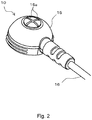
- sensor head 10 is made of resin, for example, and has a shape in which contact surface 17 in intimate contact with a patient in use is generally circular and flat, and an upper surface opposite thereto is generally domical.
- Housing 15 is formed as a closed case and holds the plurality of light-emitting elements 11 and the one light-receiving element 12 therein.
- Two linear grooves 15a are formed to be orthogonal to each other as a cross groove at the center of an upper surface of housing 15.
- the present embodiment includes four light-emitting elements 11 and one light-receiving element 12. These light-emitting elements 11 and light-receiving element 12 are mounted on substrate 13 and fixed within housing 15. Light-receiving element 12 is mounted at a position corresponding to the center of contact surface 17 of housing 15, and four light-emitting elements 11 are mounted at positions surrounding light-receiving element 12 at equal distances from light-receiving element 12 and at equal angular intervals.
- This arrangement of light-emitting elements 11 and light-receiving element 12 causes the center of light emission regions of all light-emitting elements 11 to coincide with the center of a light reception region of light-receiving element 12. Since the present embodiment includes four light-emitting elements 11, these light-emitting elements 11 are placed at an interval of 90 degrees around light-emitting element 12.
- Substrate 13 on which one light-receiving element 12 and four light-emitting elements 11 are placed as described above is fixed to housing 15 such that, for example, light-receiving element 12 is located at the intersection of two grooves 15a (see Fig. 2 ) and four light-emitting elements 11 are placed symmetrically with respect to two grooves 15a when viewed from contact surface 17.
- Opening portion 17a at the center and four opening portions 17b around opening portion 17a are formed in contact surface 17 of housing 15.
- Opening portion 17a is located at the center of contact surface 17 to be opposite to light-receiving element 12 placed within housing 15.
- Light-receiving element 12 receives light which enters into housing 15 through opening portion 17a. In this manner, the light entering into housing 15 through opening portion 17a is applied to light-receiving element 12.
- housing 15 is preferably formed not to pass external light therethrough.
- housing 15 can be made of a material which does not pass external light therethrough, an inner surface of housing 15 can be colored black by painting or the like, or a combination thereof can be used.
- Opening portions 17b are formed at equal angular intervals around opening portion 17a to be opposite to associated light-emitting elements 11. Light from each of light-emitting elements 11 is emitted to the outside of housing 15 through opposite opening portion 17b.
- the light irradiation range of light-emitting element 11 and the light reception range of light-receiving element 12 are influenced by the shapes of opening portions 17b and 17a, respectively.
- opening portions 17a and 17b preferably have circular shapes.
- Fig. 5 shows a longitudinal section view of main portions of sensor head 10 in the area in which opening portion 17a at the center is formed.
- light-transmitting member 18 which passes the light emitted by light-emitting element 11 (not shown in Fig. 5 ) is fitted in opening portion 17a from inside housing 15.
- Light-transmitting member 18 has a cross section with a size and a shape identical to those of opening portion 17a so as not to produce a gap between light-transmitting member 18 and an inner circumferential surface of opening portion 17a.
- Flange portion 18a is formed at one end of light-transmitting member 18 in a thickness direction.
- Light-transmitting member 18 is mounted with flange portion 18a located inside housing 15 and is held on an inner surface of housing 15 so as not to come off opening portion 17a by adhering flange portion 18a to the inner surface of housing 15.
- Flange portion 18a can be adhered by using an adhesive or an adhesive tape.
- Flange portion 18a included by light-transmitting member 18 structurally prevents easy entrance of a foreign matter or the chemical liquid into housing 15.
- the thickness of light-transmitting member 18 except flange portion 18a is equal to the thickness of a lower wall of housing 15, so that a lower surface of housing 15 is flush with a lower surface of light-transmitting member 18.
- opening portion 17a opposite to light-receiving element 12 in Fig. 5 opening portion 17b opposite to light-emitting element 11 is formed in the same manner such that light-transmitting member 18 is fitted and held in each of opening portions 17b from inside housing 15. Since light-transmitting member 18 is fitted in each of opening portions 17a and 17b, the overall lower surface of housing 15 forms flat contact surface 17 including the lower surfaces of light-transmitting members 18.
- Fig. 5 shows light-transmitting member 18 held on the inner surface of housing 15 through the adhesion.
- light-transmitting member 18 can be held on the inner surface of housing 15 by forming hold member 19 in housing 15 between lower wall 5a of housing 15 and substrate 13 to press flange portion 18a of light-transmitting member 18 against lower wall 5a from inside housing 15.
- flange portion 18a can be used to hold light-transmitting member 18 on housing 15 in various manners.
- the use of flange portion 18a to hold light-transmitting member 18 can reliably hold light-transmitting member 18 on housing 15 without any influence on the light passing through light-transmitting member 18.
- partition 5b is formed inside housing 15 to extend from lower wall 5a of housing 15 to substrate 13 to entirely surround opening portion 17a (each opening portion 17b) and light-receiving element 12 (each light-emitting element 11) opposite thereto.
- This can independently provide the path of the light emitting from each light-emitting element 11 to the outside of housing 15 through opening portion 17b and the path of the light reaching light-receiving element 12 from outside housing 15 through opening portion 17a, and as a result, the accuracy of leak detection can be improved.
- hold member 19 can be formed to entirely surround opening portion 17a (opening portion 17b) and light-receiving element 12 (light-emitting element 11) in order for hold member 19 to achieve the same effects as those of partition 5b shown in Fig. 5 .
- cable 16 for transmitting an electric signal extends from housing 15.
- sensor control section 20 and leak determining section 30 are electrically connected to sensor head 10 through cable 16.
- Sensor control section 20 and leak determining section 30 may be formed as an integral and independent unit separate from sensor head 10, or may be incorporated into sensor head 10, or may be provided as one of functions of a chemical liquid injector which is used together with leak detecting sensor 1 to inject a patient with a chemical liquid of interest in detection of any leak by leak detecting sensor 1.
- cable 16 can be used as a cable for power supply, for example.
- sensor control section 20 and leak determining section 30 may be formed as independent units, and one of them may be incorporated into sensor head 10, or may be provided as one of the functions of the chemical liquid injector, or may be provided independently of sensor head 10 and the chemical liquid injector.
- a combination of leak detecting sensor 1 and the chemical liquid injector is referred to as a chemical liquid injection system.
- leak detecting sensor 1 can also include a display device and/or a sound output device in order to notify an operator of the determination result of leak determining section 30.
- sensor control section 20 and leak determining section 30 are formed as one of the functions of the chemical liquid injector, these sensor control section 20 and leak determining section 30 are incorporated into the chemical liquid injector, so that sensor head 10 is connected to the chemical liquid injector through cable 16. Cable 16 may be connected removably to the chemical liquid injector through an appropriate connector (not shown).
- a power source (not shown) is connected to leak detecting sensor 1, and leak detecting sensor 1 operates on power supplied from the power source.
- the power source can be provided by using a DC power source which receives an AC power from a commercial power source and outputs a predetermined DC power, or a battery such as a dry battery, a secondary battery, and a fuel cell.
- a dedicated power source is typically prepared for operating leak detecting sensor 1.
- sensor control section 20 When sensor control section 20 is incorporated in the chemical liquid injector, a power source for supplying power to the chemical liquid injector can be shared with the chemical liquid injector to supply power from the power source for the chemical liquid injector to sensor control section 20.
- Leak determining section 30 is preferably connected to a control section of the chemical liquid injector such that the leak detection signal output from leak determining section 30 is input to the control section of the chemical liquid injector. This allows the control section of the chemical liquid injector to stop the injection operation of the chemical liquid based on the input leak detection signal to minimize the leak.
- sensor head 10 As described above, in the leak detecting sensor, all the functions can be contained in sensor head 10, some of the functions can be provided by the unit independent of sensor head 10, some of the functions can be incorporated and provided in the chemical liquid injector, or some of the functions can be provided by the unit independent of sensor head 10 and some of the remaining functions can be incorporated and provided in the chemical liquid injector.
- the connection between sensor head 10 and the unit provided independently of sensor head 10 can be achieved with wired connection through cable 16 described above or the like or wireless connection.
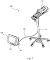
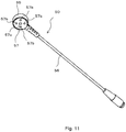
- the chemical liquid injector is described with reference to Fig. 7 and Fig. 8 .
- chemical liquid injector 100 has injection head 110 pivotally attached to the top of stand 111 and injection control unit 101 connected electrically to injection head 110 through cable 102.
- Injection control unit 101 has main operation panel 103 and touch panel 104 doubling as display means and input means.
- Injection control unit 101 may further include a hand-held unit (not shown) which is auxiliary input means connected electrically to a body of injection control unit 101 through a cable, not shown.
- Injection control unit 101 includes a single computer unit including a CPU, a RAM, and a ROM which functions as a control section for controlling the overall operation of the chemical liquid injector.
- sensor control section 20 and leak determining section 30 (see Fig. 1 ) of leak detecting sensor 1 are provided as one of the functions of chemical liquid injector 100, sensor control section 20 and leak determining section 30 can be configured within the computer unit.
- the determination result of leak determining section 30 can be displayed on touch panel 104.
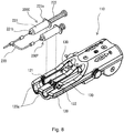
- syringes 200C and 200P are removably mounted side by side on injection head 110.
- Each of syringes 200C and 200P has cylinder 221 having cylinder flange 221a formed at a trailing end and nozzle portion 221b formed at a leading end and piston 222 inserted into cylinder 221 to be movable forward and backward.
- syringes 200C and 200P When piston 222 is moved forward toward the leading end of cylinder 221, the chemical liquid filled therein is pushed from each of syringes 200C and 200P through nozzle portion 221b.
- Nozzle portions 221b of syringes 200C and 200P are connected to two trailing ends of extension tube 230 connected to an injection needle at a leading end and branched into two at some midpoint.
- Syringes 200C and 200P, extension tube 230 and the like constitute a syringe unit.
- the injection needle can be inserted into a blood vessel of a patient to inject the chemical liquid filled in syringes 200C and 200P into the patient.
- Examples of the chemical liquid filled in syringes 200C and 200P include a contrast medium and physiological saline.
- a contrast medium for example, one syringe 200C can be filled with the contrast medium, and the other syringe 200P can be filled with the physiological saline.
- Syringe receiver 120 for placing two syringes 200C and 200P thereon is formed in a leading end portion on an upper surface of injection head 110.
- Syringe receiver 120 has two concave portions 120a each formed to receive an outer circumferential surface of cylinder 221.
- Syringe adapters 121 and 122 are removably mounted on syringe receiver 120 to hold cylinder flanges 221a of syringes 200C and 200P.
- Syringes 200C and 200P mounted on syringe receiver 120 are fixedly mounted on injection head 110 by placing each cylinder 221 in concave portion 121 with nozzle portion 221b directed toward the leading end and holding cylinder flange 221a.
- syringes 200C and 200P vary in size and/or shape, and it is difficult to hold cylinder flanges 221a of all those types of syringes 200C and 200P on a common holding structure.
- a plurality of types of syringe adapters 121 and 122 having holding structures appropriate for respective holding cylinder flanges 221a and removably mounted on syringe receiver 120 are prepared for the respective shapes of syringes 200C and 200P to be mounted.
- Syringe adapters 121 and 121 can be exchanged depending on the types of syringes 200C and 200P to mount various sizes and/or syringes 200C and 200P on injection head 110.
- two piston driving mechanisms 130 driven independently for individually or simultaneously moving pistons 222 of mounted syringes 200C and 200P forward/backward are provided in association with the positions in which syringes 200C and 200P are mounted.
- Piston driving mechanism 130 has a driving motor (not shown), a motion transformation mechanism (not shown) for transforming a rotation output of the driving motor into a linear motion, and a piston holding mechanism (not shown) connected to the motion transformation mechanism and holding a trailing end of piston 222 to be freely engaged or disengaged in order to move piston 222 forward and backward. Since such piston driving mechanism 130 can be provided by using a known mechanism typically used in the chemical liquid injector, detailed description thereof is omitted herein.
- injection head 110 For injecting the chemical liquid with chemical liquid injector 100, injection head 110 is set in a treatment room where a patient stands by, and injection control unit 101 is often set in an operation room different from the treatment room.
- sensor control section 20 and leak determining section 30 of leak detecting apparatus 1 are provided as one of the functions of chemical liquid injector 100, sensor head 10 fixed to the patient is preferably connected to injection head 110 placed near the patient, rather than to injection control unit 101.
- the injection needle Prior to the fixing of sensor head 1 to the patient, the injection needle is inserted into a blood vessel of the patient.
- the injection needle is typically inserted into a blood vessel of an arm of the patient.
- sensor head 10 is fixed to the patient with an adhesive sheet such that the center of contact surface 17 (the center of sensor head 10) is located substantially immediately above a leading end of the inserted injection needle, and preferably, the leading end of the injection needle is located toward the front of the center of contact surface 17 (the center of sensor head 10).
- grooves 15a are formed in the upper surface of housing 15 as described above, the intersection of grooves 15a can be located substantially immediately above the leading end of the injection needle, preferably at a position ahead of the leading end of the injection needle, to perform proper positioning of the injection needle and sensor head 10 easily. Since the injection needle is inserted along the blood vessel, housing 15 is fixed such that the longitudinal direction of one of grooves 15 formed in housing 15 coincides with the insertion direction of the injection needle, which can place light-emitting elements 11 symmetrically with respect to the blood vessel. This allows more favorable detection of an extravascular leak of the contrast medium.
- Grooves 15 formed in the upper surface of housing 15 in the present embodiment function as a mark representing the guide of a position and/or an orientation in fixing sensor head 10 (housing 15) to the patient.
- grooves 15 may have an arbitrary shape without being limited to the cross shape.
- the guide provided in the upper surface of housing 15 can have an arbitrary form which can be visually recognized, and may be formed as a protruding portion or formed by printing, instead of grooves 15.
- a double-sided adhesive sheet or a single-sided adhesive sheet can be used as the adhesive sheet for fixing sensor head 10 to the patient.
- sensor head 10 can be fixed to the patient by putting the double-sided adhesive sheet onto the body surface of the patient and then pressing contact surface 17 of sensor head 10 onto the adhesive sheet.
- the single-sided adhesive sheet having a relatively large area can be used as the adhesive sheet.
- sensor head 10 can be fixed to the patient by putting sensor head 10 and the single-sided adhesive sheet onto the patient so that sensor head 10 is covered with the adhesive sheet.
- both of them can be used together.
- housing 15 of sensor head 10 is formed in the domical shape.
- sensor head 10 When sensor head 10 is covered with the adhesive sheet and fixed, sensor head 10 can be fixed to the patient more stably since the adhesion area of the adhesive sheet to housing 15 is larger as compared with the case where sensor head 10 has a flat upper surface.
- sensor head 10 After sensor head 10 is fixed to the patient, the operator performs a predetermined operation to start leak detecting operation by leak detecting sensor 1.
- light-emitting elements 11 are pulsed-driven and caused to emit light.
- the emitted light passes through opening portion 17b and irradiates the patient.
- the light applied to the patient is partially reflected on the body surface and within the body of the patient. Part of the reflected light enters into housing 15 through opening portion 17a and is received by light-receiving element 12.
- Light-receiving element 12 outputs an electric output value (for example, a voltage value or a current value) in accordance with the intensity of the received light to leak detecting section 30.
- leak determining section 30 determines that the extravascular leak occurs when the change of the output value from light-receiving element 12 is larger than a predetermined level.
- the determination result of leak determining section 30 is used similarly to the conventional case, and for example, is output to the control section of the chemical liquid injector.
- the control section of the chemical liquid injector displays the occurrence of the extravascular leak on the display device and/or stops the injection operation of the chemical liquid.
- leak detecting sensor 1 of the present embodiment since four light-emitting elements 11 are placed around one light-receiving element 12, the center of the overall irradiation range provided by combining the irradiation ranges of light from all light-emitting elements 11 substantially coincides with the center of the light reception range of light-receiving element 12. Consequently, when sensor head 10 is fixed to the patient in any orientation, the leak of the chemical liquid can be detected without dependence on the orientation of sensor head 10, thereby improving the flexibility in fixing sensor head 10 to the patient.
- the region of contact surface 17 including at least the periphery of opening portion 17a is colored black to allow contact surface 17 to absorb the external light easily in the present embodiment. This can further reduce the influence of the external light to provide more stable detection results.
- the peeling of sensor head 10 can be detected as described below, for example.
- light-receiving element 12 detects disturbance light to result in a higher intensity of received light, so that the output value is higher than that when the disturbance light is not detected.
- the output value from light-receiving element 12 in the timing of detection of the light from light-emitting elements 11 is higher than the output value at the absence of an extravascular leak of the chemical liquid
- light-receiving element 12 receives the light other than the light from light-emitting elements 11, that is, the disturbance light, and leak determining section 30 can determine that sensor head 10 is peeled.
- Four light-emitting elements 11 may be driven simultaneously or may be driven in different light-emission timings, or may be driven in combination thereof to alternate the simultaneous driving of all light-emitting elements 11 and the driving in different light-emission timings.
- the simultaneous driving of all light-emitting elements 11 a large amount of light can be provided to detect a leak at a site deep below the body surface.
- the number of light-emitting elements 11 to be driven and the order of the driving are arbitrarily set as long as all light-emitting elements 11 are driven uniformly.
- light-emitting elements 11 can be driven one by one in predetermined timings clockwise or counterclockwise.
- all light-emitting elements 11 are divided into two groups each consisting of opposite pairs, and the groups can be alternately driven in predetermined and different light-emission timings.
- the light-emitting element 11 to be driven and the driving timing of light-emitting element 11 are controlled by sensor control section 20.
- sensor control section 20 When light-emitting elements 11 are driven in different light-emission timings in this manner such that only some of them emit light at a time, a site of a leak of the chemical liquid, when detected, can be roughly predicted on the basis of light-emitting element 11 driven in the timing in which the leak is detected.
- leak detecting sensor 1 of the present embodiment light-transmitting member 18 is fitted in each of opening portions 17a and 17b formed in housing 15 for passing the light therethrough to provide contact surface 17 as the flat surface with no concaves or convexes.
- a foreign matter or the chemical liquid does not tend to stay on contact surface 17, which can prevent a reduction in detection sensitivity due to the foreign matter or the chemical liquid.
- light-transmitting member 1018 of a flat plate shape is held to close opening portion 1017a from inside a housing in a typical conventional sensor head. Even when contact surface 1017 is brought into intimate contact with a patient, an air layer which prevents intimate contact with the patient is formed between the body surface of the patient and light-transmitting member 1018 at opening portion 1017a. Light emitted to the patient by light-emitting element 1011 and light reflected within the body of the patient and incident on light-receiving element 1012 pass through the air layer.
- the air layer acts as various lenses since the air layer varies in thickness or shape of an interface to the body surface of the patient due to different forces for pressing the sensor head against the patient or different elasticity levels of the body of the patient, the air layer is a cause of unstable detection results.
- light-transmitting member 18 is fitted in each of opening portions 17a and 17b, so that light-transmitting member 18 is in intimate contact with the patient in the areas in which opening portions 17a and 17b are formed.
- the light emitted by light-emitting element 11 does not pass through the air layer as conventional methods but is reflected within the body of the patient and incident on light-receiving element 12.
- light-transmitting member 18 is in intimate contact with the patient in the sites in which opening portions 17a and 17b are formed, a certain intimate contact state can be achieved between contact surface 17 and the patient. This can provide stable detection results which do not depend on the pressing force of sensor head 10 to the patient or the elasticity of the body of the patient.
- the above embodiment has been described in the case where the number of light-emitting elements 11 is four.
- the number may be two, three, or five or more as long as light-emitting elements 11 are placed to surround light-receiving element 12.
- the driving of light-emitting elements 11 can be performed as described above such that light-emitting elements 11 are driven one by one in different light-emission timings, or light-emitting elements 11 are divided into a plurality of groups each consisting of a plurality of light-emitting elements 11 and the respective groups are driven in different light-emission timings.
- the number of light-emitting elements 11 is smaller, the effect of eliminating the dependence on the orientation of sensor head 10 and the stable detection performance as described above tend to reduce.
- the number of light-emitting elements 11 is larger, sensor head 10 is complicated in structure and increased in size.
- the number of light-emitting elements 11 is determined in view of the balance between them, and specifically, the number from four to six is preferable.
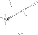
- sensor head 10 including housing 15 formed in the domical shape
- the housing may have an arbitrary shape as long as the surface in contact with the patient is flat.
- sensor head 50 can have housing 55 having a flat cylindrical shape including one end surface as contact surface 57.
- a plurality of light-emitting elements (not shown) and one light-receiving element (not shown) are placed within housing 55 similarly to the embodiment described above.
- One opening portion 57a associated with the light-receiving element and a plurality of opening portions 57b associated with the light-emitting elements are formed in contact surface 57 to be attached to the patient.
- a plurality of protruding portions 55a of a cross shape are formed in an upper surface of housing 55 for use in positioning of sensor head 50 and an injection needle in fixing sensor head 50 to the patient.
- the light-emitting elements and the light-receiving element placed within housing 55 can be connected to the chemical liquid injector through cable 56.
Landscapes
- Health & Medical Sciences (AREA)
- Engineering & Computer Science (AREA)
- Life Sciences & Earth Sciences (AREA)
- Biomedical Technology (AREA)
- Heart & Thoracic Surgery (AREA)
- Animal Behavior & Ethology (AREA)
- General Health & Medical Sciences (AREA)
- Public Health (AREA)
- Veterinary Medicine (AREA)
- Vascular Medicine (AREA)
- Anesthesiology (AREA)
- Hematology (AREA)
- Physics & Mathematics (AREA)
- Condensed Matter Physics & Semiconductors (AREA)
- Electromagnetism (AREA)
- General Physics & Mathematics (AREA)
- Computer Hardware Design (AREA)
- Microelectronics & Electronic Packaging (AREA)
- Power Engineering (AREA)
- Biophysics (AREA)
- Pathology (AREA)
- Medical Informatics (AREA)
- Molecular Biology (AREA)
- Surgery (AREA)
- Infusion, Injection, And Reservoir Apparatuses (AREA)
- Measurement Of The Respiration, Hearing Ability, Form, And Blood Characteristics Of Living Organisms (AREA)
Claims (9)
- Ein Leckdetektionssensor, der zur Erkennung einer Leckage einer in eine Blutader eines Patienten zu injizierenden chemischen Flüssigkeit in die Umgebung der Blutader ausgebildet ist, wobei die Leckdetektionssensor aufweist:eine Mehrzahl von Licht emittierenden Elementen (11), die jeweils Licht emittieren, das dem Patienten appliziert wird,ein einziges Licht empfangendes Element (12), das das von der Mehrzahl von Licht emittierenden Elementen emittierte und von dem Patienten reflektierte Licht empfängt,eine Sensor-Kontroll-Sektion (20), die ausgebildet ist, um zu kontrollieren, welches Licht emittierende Elemente (11) in welchem Zeitintervall in Übereinstimmung mit einer vorgegebenen Methode betrieben wird,eine Leckbestimmungs-Sektion (30), die ausgebildet ist, um eine Leckage der chemischen Flüssigkeit auf der Grundlage einer Ausgabe des Licht empfangenden Elements (12) zu erkennen, undwobei die Mehrzahl von Licht emittierenden Elementen (11) derart platziert ist, dass sie das einzige Licht empfangende Element (12) umgeben;dadurch gekennzeichnet, dassdie Sensor-Kontroll-Sektion (20) die Licht emittierenden Elemente (11) in unterschiedlichen Licht emittierenden Zeitintervallen derart betreibt, dass nur eines oder einige der Licht emittierenden Elemente (11) Licht zu einem Zeitpunkt emittieren.
- Der Leckdetektionssensor nach Anspruch 1 ferner aufweisend ein Gehäuse (15; 55), das die Licht emittierenden Elemente (11) und das Licht empfangende Element (12) hält,
wobei das Gehäuse (15; 55) eine Mehrzahl von Öffnungsabschnitten (17a, 17b; 57a, 57b) aufweist, die darin ausgebildet sind, um das Licht durchzulassen, wobei die Öffnungsabschnitte (17a, 17b; 57a, 57b) an Positionen, die den Licht emittierenden Elementen (11) und dem Licht empfangenden Element (12) gegenüberliegen, ausgebildet sind, und das Gehäuse (15; 55) eine Kontaktfläche (17; 57) hat, die beim Gebrauch mit der Oberfläche des Körpers des Patienten in einen engen Kontakt gebracht wird. - Der Leckdetektionssensor nach Anspruch 2, wobei der dem Licht empfangenden Element (12) gegenüberliegende Öffnungsabschnitt (17a, 17b; 57a, 57b) im Zentrum der Kontaktfläche (17; 57) ausgebildet ist.
- Der Leckdetektionssensor nach Anspruch 2, wobei eine obere Oberfläche des Gehäuses (15; 55) in einer beulenförmigen Form ausgebildet ist, wobei die obere Oberfläche der Kontaktfläche (17; 57) gegenüberliegt.
- Der Leckdetektionssensor nach Anspruch 2, wobei das Gehäuse (15; 55) eine flache zylindrische Form hat, wobei eine Endfläche die Kontaktfläche (17; 57) bildet.
- Der Leckdetektionssensor nach Anspruch 2, wobei ein Licht übertragendes Teil (18), das das von dem Licht emittierenden Element (11) emittierte Licht überträgt, in den Öffnungsabschnitt (17a, 17b; 57a, 57b) eingepasst ist, wodurch die Kontaktfläche (17; 57) flach ist umfassend eine untere Oberfläche des Licht übertragenden Teils (18).
- Der Leckdetektionssensor nach Anspruch 1, wobei die Mehrzahl der Licht emittierenden Elemente (11) gleichzeitig betrieben wird.
- Der Leckdetektionssensor nach Anspruch 1, wobei die Mehrzahl der Licht emittierenden Elemente (11) in eine Mehrzahl von Gruppen unterteilt ist, und die Gruppen in unterschiedlichen Lichtabstrahlungs-Zeitintervallen betrieben werden.
- Ein Injektionssystem für chemische Flüssigkeit aufweisend:den Leckdetektionssensor (100) nach einem der Ansprüche 1 bis 8; und einen Injektor (100) für chemische Flüssigkeit zum Injizieren einer chemischen Flüssigkeit, wobei das Erkennen einer Leckage mit dem Leckdetektionssensor von Interesse ist,wobei der Injektor (100) für chemische Flüssigkeit den Vorgang des Injizierens der chemischen Flüssigkeit und den Betrieb des Leckdetektionssensors steuert.
Applications Claiming Priority (2)
| Application Number | Priority Date | Filing Date | Title |
|---|---|---|---|
| JP2011078737 | 2011-03-31 | ||
| PCT/JP2012/058725 WO2012133845A1 (ja) | 2011-03-31 | 2012-03-30 | 漏出検出センサおよび薬液注入システム |
Publications (3)
| Publication Number | Publication Date |
|---|---|
| EP2692375A1 EP2692375A1 (de) | 2014-02-05 |
| EP2692375A4 EP2692375A4 (de) | 2014-12-17 |
| EP2692375B1 true EP2692375B1 (de) | 2018-05-30 |
Family
ID=46931538
Family Applications (1)
| Application Number | Title | Priority Date | Filing Date |
|---|---|---|---|
| EP12765349.1A Active EP2692375B1 (de) | 2011-03-31 | 2012-03-30 | Leckdetektionssensor und arzneimittelinfusionssystem |
Country Status (5)
| Country | Link |
|---|---|
| US (1) | US9905721B2 (de) |
| EP (1) | EP2692375B1 (de) |
| JP (5) | JP5968872B2 (de) |
| CN (2) | CN106955398B (de) |
| WO (1) | WO2012133845A1 (de) |
Families Citing this family (16)
| Publication number | Priority date | Publication date | Assignee | Title |
|---|---|---|---|---|
| US20130338512A1 (en) | 2012-03-12 | 2013-12-19 | Ivwatch, Llc | System and Method for Mitigating the Effects of Tissue Blood Volume Changes to Aid in Diagnosing Infiltration or Extravasation in Animalia Tissue |
| ITTO20130523A1 (it) * | 2013-06-26 | 2014-12-27 | Eltek Spa | Dispositivo medicale di rilevazione di una perdita di fluido su un soggetto |
| NO2689315T3 (de) | 2014-10-28 | 2018-04-14 | ||
| US11129934B2 (en) | 2014-10-28 | 2021-09-28 | Bayer Healthcare Llc | Self-orienting pressure jacket and pressure jacket-to-injector interface |
| BR112017008878B1 (pt) | 2014-10-28 | 2022-10-11 | Bayer Healthcare Llc | Camisa de pressão |
| US9199033B1 (en) | 2014-10-28 | 2015-12-01 | Bayer Healthcare Llc | Self-orienting syringe and syringe interface |
| JP6552258B6 (ja) * | 2015-05-01 | 2019-09-04 | 学校法人 岩手医科大学 | 漏出検出装置 |
| CN108472433B (zh) | 2015-11-13 | 2021-12-14 | 拜耳医药保健有限公司 | 嵌套式针筒组装件 |
| CN106289453B (zh) * | 2016-08-22 | 2023-12-01 | 绵阳高新区恒奥电子科技有限公司 | 用于加油站渗漏检测的液位检测装置 |
| TWI668420B (zh) * | 2017-02-23 | 2019-08-11 | 張寅 | Infusion leak detection, blocking device and monitoring system |
| JP7296887B2 (ja) * | 2017-04-20 | 2023-06-23 | ベクトン・ディキンソン・アンド・カンパニー | インスリンの流れを停止させる電気的な制御を備えたインスリン漏れセンサ |
| US11191893B2 (en) | 2018-01-31 | 2021-12-07 | Bayer Healthcare Llc | System and method for syringe engagement with injector |
| CN115151298A (zh) | 2020-02-21 | 2022-10-04 | 拜耳医药保健有限责任公司 | 用于医疗流体递送的流体路径连接器 |
| CN115485783A (zh) | 2020-04-30 | 2022-12-16 | 拜耳医药保健有限责任公司 | 用于保护患者的健康以进行流体注射的系统、设备和方法 |
| EP4168064A1 (de) | 2020-06-18 | 2023-04-26 | Bayer HealthCare, LLC | Inline-luftblasen-suspensionsvorrichtung für flüssigkeitswege eines angiographie-injektors |
| WO2023149570A1 (ja) * | 2022-02-07 | 2023-08-10 | 株式会社根本杏林堂 | 生体組織の解析方法及び生体組織の異常を検出する装置 |
Family Cites Families (25)
| Publication number | Priority date | Publication date | Assignee | Title |
|---|---|---|---|---|
| JPS51140673A (en) * | 1975-05-28 | 1976-12-03 | Meruka Denshi Kk | Turbiditimeter |
| JPS5453889U (de) * | 1977-09-22 | 1979-04-13 | ||
| JPH0450009Y2 (de) * | 1986-12-23 | 1992-11-25 | ||
| US4880304A (en) | 1987-04-01 | 1989-11-14 | Nippon Colin Co., Ltd. | Optical sensor for pulse oximeter |
| JPH0315502U (de) * | 1989-06-28 | 1991-02-15 | ||
| JP3416257B2 (ja) * | 1994-05-10 | 2003-06-16 | 三洋電機株式会社 | 脈拍検出装置 |
| JPH11318840A (ja) * | 1998-05-14 | 1999-11-24 | Omron Corp | 脈波検出装置 |
| JP4701468B2 (ja) * | 1998-12-24 | 2011-06-15 | パナソニック電工株式会社 | 生体情報測定装置 |
| US6408204B1 (en) * | 1999-07-28 | 2002-06-18 | Medrad, Inc. | Apparatuses and methods for extravasation detection |
| US6487428B1 (en) * | 2000-08-31 | 2002-11-26 | Trustees Of The University Of Pennsylvania | Extravasation detection apparatus and method based on optical sensing |
| US7169107B2 (en) * | 2002-01-25 | 2007-01-30 | Karen Jersey-Willuhn | Conductivity reconstruction based on inverse finite element measurements in a tissue monitoring system |
| JP2004024514A (ja) * | 2002-06-25 | 2004-01-29 | Matsushita Electric Works Ltd | 生体信号測定用ピックアップ具及び生体信号測定装置 |
| JP4443957B2 (ja) * | 2003-04-28 | 2010-03-31 | 株式会社根本杏林堂 | 漏出検出装置および方法 |
| JP2006528045A (ja) * | 2003-05-22 | 2006-12-14 | インスペクター リサーチ システムズ ベーフェー | 組織検査及び画像処理のための蛍光フィルタ |
| US20040240716A1 (en) * | 2003-05-22 | 2004-12-02 | De Josselin De Jong Elbert | Analysis and display of fluorescence images |
| JP2006068491A (ja) * | 2004-08-02 | 2006-03-16 | Nippon Seimitsu Sokki Kk | 血液の流動性評価方法及び装置 |
| JP4762147B2 (ja) * | 2004-09-14 | 2011-08-31 | 株式会社根本杏林堂 | 漏出検出装置 |
| US7826890B1 (en) * | 2005-12-06 | 2010-11-02 | Wintec, Llc | Optical detection of intravenous infiltration |
| US7722562B2 (en) * | 2006-03-02 | 2010-05-25 | Tyco Healthcare Group Lp | Pump set with safety interlock |
| JP2008212258A (ja) * | 2007-03-01 | 2008-09-18 | Fuji Xerox Co Ltd | 光学検出装置、光学式血流計および光学検出方法 |
| US9011334B2 (en) * | 2007-09-27 | 2015-04-21 | Baxter International Inc. | Access disconnect detection |
| WO2010058796A1 (ja) * | 2008-11-19 | 2010-05-27 | 株式会社根本杏林堂 | 漏出検出システム |
| JP2010252875A (ja) * | 2009-04-21 | 2010-11-11 | Panasonic Corp | 光電式生体測定装置 |
| CN201519331U (zh) * | 2009-10-13 | 2010-07-07 | 钟聪 | 一种医用输液时渗漏的检测装置 |
| KR100997444B1 (ko) * | 2009-11-17 | 2010-11-30 | (주)에이치쓰리시스템 | 광용적맥파 측정기 |
-
2012
- 2012-03-30 CN CN201710266523.4A patent/CN106955398B/zh active Active
- 2012-03-30 WO PCT/JP2012/058725 patent/WO2012133845A1/ja active Application Filing
- 2012-03-30 CN CN201280025381.8A patent/CN103596608B/zh not_active Expired - Fee Related
- 2012-03-30 JP JP2013507825A patent/JP5968872B2/ja active Active
- 2012-03-30 EP EP12765349.1A patent/EP2692375B1/de active Active
- 2012-04-23 US US13/453,108 patent/US9905721B2/en active Active
-
2016
- 2016-07-06 JP JP2016133812A patent/JP6286485B2/ja active Active
-
2018
- 2018-02-05 JP JP2018018010A patent/JP6577070B2/ja active Active
-
2019
- 2019-08-21 JP JP2019151346A patent/JP6945871B2/ja active Active
-
2021
- 2021-09-08 JP JP2021146006A patent/JP2021191467A/ja active Pending
Non-Patent Citations (1)
| Title |
|---|
| None * |
Also Published As
| Publication number | Publication date |
|---|---|
| WO2012133845A1 (ja) | 2012-10-04 |
| JPWO2012133845A1 (ja) | 2014-07-28 |
| JP6286485B2 (ja) | 2018-02-28 |
| CN103596608B (zh) | 2017-05-17 |
| CN103596608A (zh) | 2014-02-19 |
| JP2016190069A (ja) | 2016-11-10 |
| JP2018102939A (ja) | 2018-07-05 |
| JP6577070B2 (ja) | 2019-09-18 |
| EP2692375A1 (de) | 2014-02-05 |
| CN106955398B (zh) | 2020-04-17 |
| JP2020006187A (ja) | 2020-01-16 |
| JP6945871B2 (ja) | 2021-10-06 |
| JP2021191467A (ja) | 2021-12-16 |
| JP5968872B2 (ja) | 2016-08-10 |
| EP2692375A4 (de) | 2014-12-17 |
| US20130109967A1 (en) | 2013-05-02 |
| US9905721B2 (en) | 2018-02-27 |
| CN106955398A (zh) | 2017-07-18 |
Similar Documents
| Publication | Publication Date | Title |
|---|---|---|
| EP2692375B1 (de) | Leckdetektionssensor und arzneimittelinfusionssystem | |
| US10688312B2 (en) | Medical device with radiation delivery | |
| EP1800704B1 (de) | Leckdetektor | |
| US8773660B2 (en) | Arrangement for determining a longitudinal position of a stopper | |
| JP5882595B2 (ja) | 漏出検出センサおよび薬液注入システム | |
| US10342915B2 (en) | Sensor pad kit for leak detection sensor, leak detection system, and chemical liquid injection system | |
| EP2931336A1 (de) | Nachweisvorrichtung und injektionsvorrichtung damit | |
| US20080154202A1 (en) | Controller | |
| WO2010029521A2 (en) | Vein locator and associated devices | |
| KR20160075907A (ko) | 슬라이딩 장착유닛이 구비된 약물주입기 | |
| WO2011087059A1 (ja) | 漏出検出ユニットおよび漏出検出システム | |
| JP6552258B2 (ja) | 漏出検出装置 | |
| US20090326444A1 (en) | Double-sided adhesive sheet | |
| US20240130640A1 (en) | Syringe with Integrated Vein Finder | |
| TW201822828A (zh) | 光纖注射及抽吸裝置 | |
| US20230158230A1 (en) | Infusion apparatus and method for testing extravasation | |
| WO2023179121A1 (zh) | 医疗内窥镜设备及医疗内窥镜摄像系统 | |
| WO2024091467A1 (en) | Syringe with integrated vein finder | |
| KR20240071639A (ko) | 경혈 레이저 침 | |
| CN114364434A (zh) | 光治疗装置及光治疗装置的工作方法 |
Legal Events
| Date | Code | Title | Description |
|---|---|---|---|
| PUAI | Public reference made under article 153(3) epc to a published international application that has entered the european phase |
Free format text: ORIGINAL CODE: 0009012 |
|
| 17P | Request for examination filed |
Effective date: 20131007 |
|
| AK | Designated contracting states |
Kind code of ref document: A1 Designated state(s): AL AT BE BG CH CY CZ DE DK EE ES FI FR GB GR HR HU IE IS IT LI LT LU LV MC MK MT NL NO PL PT RO RS SE SI SK SM TR |
|
| DAX | Request for extension of the european patent (deleted) | ||
| A4 | Supplementary search report drawn up and despatched |
Effective date: 20141119 |
|
| RIC1 | Information provided on ipc code assigned before grant |
Ipc: A61M 5/00 20060101ALI20141113BHEP Ipc: A61M 5/145 20060101ALI20141113BHEP Ipc: A61M 5/168 20060101AFI20141113BHEP |
|
| GRAP | Despatch of communication of intention to grant a patent |
Free format text: ORIGINAL CODE: EPIDOSNIGR1 |
|
| STAA | Information on the status of an ep patent application or granted ep patent |
Free format text: STATUS: GRANT OF PATENT IS INTENDED |
|
| INTG | Intention to grant announced |
Effective date: 20171220 |
|
| GRAS | Grant fee paid |
Free format text: ORIGINAL CODE: EPIDOSNIGR3 |
|
| GRAA | (expected) grant |
Free format text: ORIGINAL CODE: 0009210 |
|
| STAA | Information on the status of an ep patent application or granted ep patent |
Free format text: STATUS: THE PATENT HAS BEEN GRANTED |
|
| AK | Designated contracting states |
Kind code of ref document: B1 Designated state(s): AL AT BE BG CH CY CZ DE DK EE ES FI FR GB GR HR HU IE IS IT LI LT LU LV MC MK MT NL NO PL PT RO RS SE SI SK SM TR |
|
| REG | Reference to a national code |
Ref country code: GB Ref legal event code: FG4D |
|
| REG | Reference to a national code |
Ref country code: CH Ref legal event code: EP |
|
| REG | Reference to a national code |
Ref country code: AT Ref legal event code: REF Ref document number: 1002960 Country of ref document: AT Kind code of ref document: T Effective date: 20180615 |
|
| REG | Reference to a national code |
Ref country code: DE Ref legal event code: R096 Ref document number: 602012046928 Country of ref document: DE |
|
| REG | Reference to a national code |
Ref country code: IE Ref legal event code: FG4D |
|
| REG | Reference to a national code |
Ref country code: NL Ref legal event code: MP Effective date: 20180530 |
|
| REG | Reference to a national code |
Ref country code: LT Ref legal event code: MG4D |
|
| PG25 | Lapsed in a contracting state [announced via postgrant information from national office to epo] |
Ref country code: CY Free format text: LAPSE BECAUSE OF FAILURE TO SUBMIT A TRANSLATION OF THE DESCRIPTION OR TO PAY THE FEE WITHIN THE PRESCRIBED TIME-LIMIT Effective date: 20180530 Ref country code: SE Free format text: LAPSE BECAUSE OF FAILURE TO SUBMIT A TRANSLATION OF THE DESCRIPTION OR TO PAY THE FEE WITHIN THE PRESCRIBED TIME-LIMIT Effective date: 20180530 Ref country code: ES Free format text: LAPSE BECAUSE OF FAILURE TO SUBMIT A TRANSLATION OF THE DESCRIPTION OR TO PAY THE FEE WITHIN THE PRESCRIBED TIME-LIMIT Effective date: 20180530 Ref country code: LT Free format text: LAPSE BECAUSE OF FAILURE TO SUBMIT A TRANSLATION OF THE DESCRIPTION OR TO PAY THE FEE WITHIN THE PRESCRIBED TIME-LIMIT Effective date: 20180530 Ref country code: NO Free format text: LAPSE BECAUSE OF FAILURE TO SUBMIT A TRANSLATION OF THE DESCRIPTION OR TO PAY THE FEE WITHIN THE PRESCRIBED TIME-LIMIT Effective date: 20180830 Ref country code: FI Free format text: LAPSE BECAUSE OF FAILURE TO SUBMIT A TRANSLATION OF THE DESCRIPTION OR TO PAY THE FEE WITHIN THE PRESCRIBED TIME-LIMIT Effective date: 20180530 Ref country code: BG Free format text: LAPSE BECAUSE OF FAILURE TO SUBMIT A TRANSLATION OF THE DESCRIPTION OR TO PAY THE FEE WITHIN THE PRESCRIBED TIME-LIMIT Effective date: 20180830 |
|
| PG25 | Lapsed in a contracting state [announced via postgrant information from national office to epo] |
Ref country code: HR Free format text: LAPSE BECAUSE OF FAILURE TO SUBMIT A TRANSLATION OF THE DESCRIPTION OR TO PAY THE FEE WITHIN THE PRESCRIBED TIME-LIMIT Effective date: 20180530 Ref country code: RS Free format text: LAPSE BECAUSE OF FAILURE TO SUBMIT A TRANSLATION OF THE DESCRIPTION OR TO PAY THE FEE WITHIN THE PRESCRIBED TIME-LIMIT Effective date: 20180530 Ref country code: LV Free format text: LAPSE BECAUSE OF FAILURE TO SUBMIT A TRANSLATION OF THE DESCRIPTION OR TO PAY THE FEE WITHIN THE PRESCRIBED TIME-LIMIT Effective date: 20180530 Ref country code: GR Free format text: LAPSE BECAUSE OF FAILURE TO SUBMIT A TRANSLATION OF THE DESCRIPTION OR TO PAY THE FEE WITHIN THE PRESCRIBED TIME-LIMIT Effective date: 20180831 |
|
| REG | Reference to a national code |
Ref country code: AT Ref legal event code: MK05 Ref document number: 1002960 Country of ref document: AT Kind code of ref document: T Effective date: 20180530 |
|
| PG25 | Lapsed in a contracting state [announced via postgrant information from national office to epo] |
Ref country code: NL Free format text: LAPSE BECAUSE OF FAILURE TO SUBMIT A TRANSLATION OF THE DESCRIPTION OR TO PAY THE FEE WITHIN THE PRESCRIBED TIME-LIMIT Effective date: 20180530 |
|
| PG25 | Lapsed in a contracting state [announced via postgrant information from national office to epo] |
Ref country code: DK Free format text: LAPSE BECAUSE OF FAILURE TO SUBMIT A TRANSLATION OF THE DESCRIPTION OR TO PAY THE FEE WITHIN THE PRESCRIBED TIME-LIMIT Effective date: 20180530 Ref country code: SK Free format text: LAPSE BECAUSE OF FAILURE TO SUBMIT A TRANSLATION OF THE DESCRIPTION OR TO PAY THE FEE WITHIN THE PRESCRIBED TIME-LIMIT Effective date: 20180530 Ref country code: EE Free format text: LAPSE BECAUSE OF FAILURE TO SUBMIT A TRANSLATION OF THE DESCRIPTION OR TO PAY THE FEE WITHIN THE PRESCRIBED TIME-LIMIT Effective date: 20180530 Ref country code: PL Free format text: LAPSE BECAUSE OF FAILURE TO SUBMIT A TRANSLATION OF THE DESCRIPTION OR TO PAY THE FEE WITHIN THE PRESCRIBED TIME-LIMIT Effective date: 20180530 Ref country code: CZ Free format text: LAPSE BECAUSE OF FAILURE TO SUBMIT A TRANSLATION OF THE DESCRIPTION OR TO PAY THE FEE WITHIN THE PRESCRIBED TIME-LIMIT Effective date: 20180530 Ref country code: AT Free format text: LAPSE BECAUSE OF FAILURE TO SUBMIT A TRANSLATION OF THE DESCRIPTION OR TO PAY THE FEE WITHIN THE PRESCRIBED TIME-LIMIT Effective date: 20180530 Ref country code: RO Free format text: LAPSE BECAUSE OF FAILURE TO SUBMIT A TRANSLATION OF THE DESCRIPTION OR TO PAY THE FEE WITHIN THE PRESCRIBED TIME-LIMIT Effective date: 20180530 |
|
| PG25 | Lapsed in a contracting state [announced via postgrant information from national office to epo] |
Ref country code: IT Free format text: LAPSE BECAUSE OF FAILURE TO SUBMIT A TRANSLATION OF THE DESCRIPTION OR TO PAY THE FEE WITHIN THE PRESCRIBED TIME-LIMIT Effective date: 20180530 Ref country code: SM Free format text: LAPSE BECAUSE OF FAILURE TO SUBMIT A TRANSLATION OF THE DESCRIPTION OR TO PAY THE FEE WITHIN THE PRESCRIBED TIME-LIMIT Effective date: 20180530 |
|
| REG | Reference to a national code |
Ref country code: DE Ref legal event code: R097 Ref document number: 602012046928 Country of ref document: DE |
|
| PLBE | No opposition filed within time limit |
Free format text: ORIGINAL CODE: 0009261 |
|
| STAA | Information on the status of an ep patent application or granted ep patent |
Free format text: STATUS: NO OPPOSITION FILED WITHIN TIME LIMIT |
|
| 26N | No opposition filed |
Effective date: 20190301 |
|
| PG25 | Lapsed in a contracting state [announced via postgrant information from national office to epo] |
Ref country code: SI Free format text: LAPSE BECAUSE OF FAILURE TO SUBMIT A TRANSLATION OF THE DESCRIPTION OR TO PAY THE FEE WITHIN THE PRESCRIBED TIME-LIMIT Effective date: 20180530 |
|
| PG25 | Lapsed in a contracting state [announced via postgrant information from national office to epo] |
Ref country code: MC Free format text: LAPSE BECAUSE OF FAILURE TO SUBMIT A TRANSLATION OF THE DESCRIPTION OR TO PAY THE FEE WITHIN THE PRESCRIBED TIME-LIMIT Effective date: 20180530 |
|
| REG | Reference to a national code |
Ref country code: CH Ref legal event code: PL |
|
| PG25 | Lapsed in a contracting state [announced via postgrant information from national office to epo] |
Ref country code: AL Free format text: LAPSE BECAUSE OF FAILURE TO SUBMIT A TRANSLATION OF THE DESCRIPTION OR TO PAY THE FEE WITHIN THE PRESCRIBED TIME-LIMIT Effective date: 20180530 Ref country code: LU Free format text: LAPSE BECAUSE OF NON-PAYMENT OF DUE FEES Effective date: 20190330 |
|
| REG | Reference to a national code |
Ref country code: BE Ref legal event code: MM Effective date: 20190331 |
|
| PG25 | Lapsed in a contracting state [announced via postgrant information from national office to epo] |
Ref country code: LI Free format text: LAPSE BECAUSE OF NON-PAYMENT OF DUE FEES Effective date: 20190331 Ref country code: IE Free format text: LAPSE BECAUSE OF NON-PAYMENT OF DUE FEES Effective date: 20190330 Ref country code: CH Free format text: LAPSE BECAUSE OF NON-PAYMENT OF DUE FEES Effective date: 20190331 |
|
| PG25 | Lapsed in a contracting state [announced via postgrant information from national office to epo] |
Ref country code: BE Free format text: LAPSE BECAUSE OF NON-PAYMENT OF DUE FEES Effective date: 20190331 |
|
| PG25 | Lapsed in a contracting state [announced via postgrant information from national office to epo] |
Ref country code: TR Free format text: LAPSE BECAUSE OF FAILURE TO SUBMIT A TRANSLATION OF THE DESCRIPTION OR TO PAY THE FEE WITHIN THE PRESCRIBED TIME-LIMIT Effective date: 20180530 |
|
| PG25 | Lapsed in a contracting state [announced via postgrant information from national office to epo] |
Ref country code: MT Free format text: LAPSE BECAUSE OF NON-PAYMENT OF DUE FEES Effective date: 20190330 Ref country code: PT Free format text: LAPSE BECAUSE OF FAILURE TO SUBMIT A TRANSLATION OF THE DESCRIPTION OR TO PAY THE FEE WITHIN THE PRESCRIBED TIME-LIMIT Effective date: 20181001 |
|
| PG25 | Lapsed in a contracting state [announced via postgrant information from national office to epo] |
Ref country code: IS Free format text: LAPSE BECAUSE OF FAILURE TO SUBMIT A TRANSLATION OF THE DESCRIPTION OR TO PAY THE FEE WITHIN THE PRESCRIBED TIME-LIMIT Effective date: 20180930 |
|
| PG25 | Lapsed in a contracting state [announced via postgrant information from national office to epo] |
Ref country code: HU Free format text: LAPSE BECAUSE OF FAILURE TO SUBMIT A TRANSLATION OF THE DESCRIPTION OR TO PAY THE FEE WITHIN THE PRESCRIBED TIME-LIMIT; INVALID AB INITIO Effective date: 20120330 |
|
| PG25 | Lapsed in a contracting state [announced via postgrant information from national office to epo] |
Ref country code: MK Free format text: LAPSE BECAUSE OF FAILURE TO SUBMIT A TRANSLATION OF THE DESCRIPTION OR TO PAY THE FEE WITHIN THE PRESCRIBED TIME-LIMIT Effective date: 20180530 |
|
| PGFP | Annual fee paid to national office [announced via postgrant information from national office to epo] |
Ref country code: FR Payment date: 20230216 Year of fee payment: 12 |
|
| PGFP | Annual fee paid to national office [announced via postgrant information from national office to epo] |
Ref country code: DE Payment date: 20240321 Year of fee payment: 13 Ref country code: GB Payment date: 20240325 Year of fee payment: 13 |