EP2689114B1 - Engine-driven work machine - Google Patents
Engine-driven work machine Download PDFInfo
- Publication number
- EP2689114B1 EP2689114B1 EP12713387.4A EP12713387A EP2689114B1 EP 2689114 B1 EP2689114 B1 EP 2689114B1 EP 12713387 A EP12713387 A EP 12713387A EP 2689114 B1 EP2689114 B1 EP 2689114B1
- Authority
- EP
- European Patent Office
- Prior art keywords
- engine
- expansion chamber
- connection duct
- work machine
- flange
- Prior art date
- Legal status (The legal status is an assumption and is not a legal conclusion. Google has not performed a legal analysis and makes no representation as to the accuracy of the status listed.)
- Not-in-force
Links
Images


Classifications
-
- F—MECHANICAL ENGINEERING; LIGHTING; HEATING; WEAPONS; BLASTING
- F01—MACHINES OR ENGINES IN GENERAL; ENGINE PLANTS IN GENERAL; STEAM ENGINES
- F01N—GAS-FLOW SILENCERS OR EXHAUST APPARATUS FOR MACHINES OR ENGINES IN GENERAL; GAS-FLOW SILENCERS OR EXHAUST APPARATUS FOR INTERNAL-COMBUSTION ENGINES
- F01N13/00—Exhaust or silencing apparatus characterised by constructional features
-
- F—MECHANICAL ENGINEERING; LIGHTING; HEATING; WEAPONS; BLASTING
- F01—MACHINES OR ENGINES IN GENERAL; ENGINE PLANTS IN GENERAL; STEAM ENGINES
- F01N—GAS-FLOW SILENCERS OR EXHAUST APPARATUS FOR MACHINES OR ENGINES IN GENERAL; GAS-FLOW SILENCERS OR EXHAUST APPARATUS FOR INTERNAL-COMBUSTION ENGINES
- F01N1/00—Silencing apparatus characterised by method of silencing
- F01N1/08—Silencing apparatus characterised by method of silencing by reducing exhaust energy by throttling or whirling
-
- F—MECHANICAL ENGINEERING; LIGHTING; HEATING; WEAPONS; BLASTING
- F01—MACHINES OR ENGINES IN GENERAL; ENGINE PLANTS IN GENERAL; STEAM ENGINES
- F01N—GAS-FLOW SILENCERS OR EXHAUST APPARATUS FOR MACHINES OR ENGINES IN GENERAL; GAS-FLOW SILENCERS OR EXHAUST APPARATUS FOR INTERNAL-COMBUSTION ENGINES
- F01N13/00—Exhaust or silencing apparatus characterised by constructional features
- F01N13/002—Apparatus adapted for particular uses, e.g. for portable devices driven by machines or engines
-
- F—MECHANICAL ENGINEERING; LIGHTING; HEATING; WEAPONS; BLASTING
- F01—MACHINES OR ENGINES IN GENERAL; ENGINE PLANTS IN GENERAL; STEAM ENGINES
- F01N—GAS-FLOW SILENCERS OR EXHAUST APPARATUS FOR MACHINES OR ENGINES IN GENERAL; GAS-FLOW SILENCERS OR EXHAUST APPARATUS FOR INTERNAL-COMBUSTION ENGINES
- F01N13/00—Exhaust or silencing apparatus characterised by constructional features
- F01N13/08—Other arrangements or adaptations of exhaust conduits
-
- F—MECHANICAL ENGINEERING; LIGHTING; HEATING; WEAPONS; BLASTING
- F01—MACHINES OR ENGINES IN GENERAL; ENGINE PLANTS IN GENERAL; STEAM ENGINES
- F01N—GAS-FLOW SILENCERS OR EXHAUST APPARATUS FOR MACHINES OR ENGINES IN GENERAL; GAS-FLOW SILENCERS OR EXHAUST APPARATUS FOR INTERNAL-COMBUSTION ENGINES
- F01N13/00—Exhaust or silencing apparatus characterised by constructional features
- F01N13/18—Construction facilitating manufacture, assembly, or disassembly
- F01N13/1888—Construction facilitating manufacture, assembly, or disassembly the housing of the assembly consisting of two or more parts, e.g. two half-shells
-
- F—MECHANICAL ENGINEERING; LIGHTING; HEATING; WEAPONS; BLASTING
- F02—COMBUSTION ENGINES; HOT-GAS OR COMBUSTION-PRODUCT ENGINE PLANTS
- F02B—INTERNAL-COMBUSTION PISTON ENGINES; COMBUSTION ENGINES IN GENERAL
- F02B27/00—Use of kinetic or wave energy of charge in induction systems, or of combustion residues in exhaust systems, for improving quantity of charge or for increasing removal of combustion residues
- F02B27/04—Use of kinetic or wave energy of charge in induction systems, or of combustion residues in exhaust systems, for improving quantity of charge or for increasing removal of combustion residues in exhaust systems only, e.g. for sucking-off combustion gases
-
- F—MECHANICAL ENGINEERING; LIGHTING; HEATING; WEAPONS; BLASTING
- F01—MACHINES OR ENGINES IN GENERAL; ENGINE PLANTS IN GENERAL; STEAM ENGINES
- F01N—GAS-FLOW SILENCERS OR EXHAUST APPARATUS FOR MACHINES OR ENGINES IN GENERAL; GAS-FLOW SILENCERS OR EXHAUST APPARATUS FOR INTERNAL-COMBUSTION ENGINES
- F01N2470/00—Structure or shape of exhaust gas passages, pipes or tubes
- F01N2470/20—Dimensional characteristics of tubes, e.g. length, diameter
-
- F—MECHANICAL ENGINEERING; LIGHTING; HEATING; WEAPONS; BLASTING
- F01—MACHINES OR ENGINES IN GENERAL; ENGINE PLANTS IN GENERAL; STEAM ENGINES
- F01N—GAS-FLOW SILENCERS OR EXHAUST APPARATUS FOR MACHINES OR ENGINES IN GENERAL; GAS-FLOW SILENCERS OR EXHAUST APPARATUS FOR INTERNAL-COMBUSTION ENGINES
- F01N2590/00—Exhaust or silencing apparatus adapted to particular use, e.g. for military applications, airplanes, submarines
- F01N2590/06—Exhaust or silencing apparatus adapted to particular use, e.g. for military applications, airplanes, submarines for hand-held tools or portables devices
-
- F—MECHANICAL ENGINEERING; LIGHTING; HEATING; WEAPONS; BLASTING
- F02—COMBUSTION ENGINES; HOT-GAS OR COMBUSTION-PRODUCT ENGINE PLANTS
- F02B—INTERNAL-COMBUSTION PISTON ENGINES; COMBUSTION ENGINES IN GENERAL
- F02B75/00—Other engines
- F02B75/02—Engines characterised by their cycles, e.g. six-stroke
- F02B2075/022—Engines characterised by their cycles, e.g. six-stroke having less than six strokes per cycle
- F02B2075/025—Engines characterised by their cycles, e.g. six-stroke having less than six strokes per cycle two
-
- F—MECHANICAL ENGINEERING; LIGHTING; HEATING; WEAPONS; BLASTING
- F02—COMBUSTION ENGINES; HOT-GAS OR COMBUSTION-PRODUCT ENGINE PLANTS
- F02B—INTERNAL-COMBUSTION PISTON ENGINES; COMBUSTION ENGINES IN GENERAL
- F02B63/00—Adaptations of engines for driving pumps, hand-held tools or electric generators; Portable combinations of engines with engine-driven devices
- F02B63/02—Adaptations of engines for driving pumps, hand-held tools or electric generators; Portable combinations of engines with engine-driven devices for hand-held tools
-
- Y—GENERAL TAGGING OF NEW TECHNOLOGICAL DEVELOPMENTS; GENERAL TAGGING OF CROSS-SECTIONAL TECHNOLOGIES SPANNING OVER SEVERAL SECTIONS OF THE IPC; TECHNICAL SUBJECTS COVERED BY FORMER USPC CROSS-REFERENCE ART COLLECTIONS [XRACs] AND DIGESTS
- Y02—TECHNOLOGIES OR APPLICATIONS FOR MITIGATION OR ADAPTATION AGAINST CLIMATE CHANGE
- Y02T—CLIMATE CHANGE MITIGATION TECHNOLOGIES RELATED TO TRANSPORTATION
- Y02T10/00—Road transport of goods or passengers
- Y02T10/10—Internal combustion engine [ICE] based vehicles
- Y02T10/12—Improving ICE efficiencies
Definitions
- aspects of the present invention relate to an engine-driven work machine such as a brush cutter, a chain saw, a blower or the like, and specifically, to a compact muffler with reduced exhaust gas and improved power characteristics, and an engine-driven work machine including the same.
- a two-cycle engine is in a wide use for portable engine-driven work machines for which compactness, lightness and high power are required. High power and fuel-efficiency are required for the two-cycle engine.
- a problem of low power and increased exhaust gas occurs to the two-cycle engine when fresh gas escapes through an exhaust hole during exhaust and scavenge.
- a system in which the number or shape of scavenge hole or exhaust hole is devised, or a layered scavenging system in which air is guided first.
- US 3 , 665, 712 discloses a two-cycle engine exhaust systems to resonance expansion chamber exhaust systems for use with two-cycle engines wherein the expansion chamber has a bend in it.
- the central axis of the chamber changes direction at least once in order to conserve overall space.
- the bend or curve in the expansion chamber provides an area used for a silencing device, without increasing the external dimensions of the overall external exhaust system.
- a muffler disclosed in JP-A-H01-92515 is configured to prevent fresh gas from escaping by using a pressure pulsation effect.
- an expansion chamber and an exhaust pipe, which are continuous to an exhaust port of the muffler, are installed separately, it is difficult to make a compact muffler.
- height, width and length of the expansion chamber are limited. Therefore, it becomes difficult to secure sufficient length of the exhaust pipe, and it becomes difficult to achieve reduced exhaust gas and high power by the pressure pulsation.
- aspects of the present invention have been conceived in view of the above-described problems, and an object thereof is to provide a compact muffler, in which a pressure pulsation effect is not destroyed, and an engine-driven work machine including the muffler.
- Another object of the aspects of the present invention is to provide a compact muffler with improvement in disposing a connection duct that connects an exhaust port of an engine and an opening of the muffler and an engine-driven work machine including the muffler.
- Another object of the aspects of the present invention is to provide an engine-driven work machine including a muffler which is disposed in a space between a front end tool and an engine without widening a distance between the operating center of the front end tool and the engine.
- an engine-driven work machine including: a two-cycle engine including a piston which is configured to reciprocally move inside a cylinder to which an exhaust port is formed; and a front end tool configured to be driven by the engine, wherein an expansion chamber is connected to the exhaust port via a connection duct, wherein the connection duct includes a first end and a second end, and the connection duct extends from the first end in an axial direction of the exhaust port, is bent in a direction away from an axis of the exhaust port and is connected to the expansion chamber at the second end, and wherein a housing of the expansion chamber is disposed at an inner side of the connection duct and an engine block including the cylinder and a crank case.
- connection duct extends from the first end in the axial direction of the exhaust port, is bent in a direction away from the axis of the exhaust port and is connected to the expansion chamber at the second end, and the housing of the expansion chamber is arranged at an inner side of the engine block and the connection duct, it is possible to secure sufficient length of the connection duct tunable with a normal rotational speed of 8,000 rpm to 9,000 rpm in a space with limited height, width and length such as a space between a rotation part of an engine cutter and the engine.
- connection duct is curved toward a crank case and below the cylinder axis so that exhaust gas that emerges from the exhaust port flows toward the crank case, it is possible to make a significantly compact muffler.
- connection duct has a U-shape in which the second end , which may be connected to the expansion chamber faces the crank case of the engine.
- connection duct has a U-shape in which the second end connected to the expansion chamber faces the crank case of the engine, it is possible to secure sufficient length of the connection duct with a simple structure.
- connection duct may include a branching portion, and a U-shaped branch pipe having a closed end may be connected to the branching portion.
- connection duct since a U-shaped branch pipe having a closed end is connected to the connection duct, it is possible to reliably achieve an exhaust pressure pulsation effect.
- the expansion chamber can be applied to a number of tuning revolution of pulsation or different engine displacements only by changing length or sectional area of the connection duct and the branch pipe, it is possible to promote common use of the expansion chamber.
- a first flange and a second flange may be fixed to both ends of the connection duct, respectively, and the first flange may be joined to the exhaust port and the second flange may be joined to the expansion chamber.
- first and second flanges are fixed to both ends of the connection duct, the first flange is joined to the exhaust port and the second flange is joined to the expansion chamber, it is possible to strongly fix the expansion chamber to the engine using the screws or bolts for joining the connection duct to the exhaust port of the cylinder.
- the expansion chamber may have a wall having a shape following an inner circumference side shape of the connection duct, and a radius of curvature R1 of an upper side of the connection duct may be larger than a radius of curvature R2 of a lower side of the connection duct.
- the expansion chamber has a wall having a shape following an inner circumference of the connection duct, it is possible to secure a sufficient volume of the expansion chamber.
- the connection duct is installed to extend in an extension line direction of the axis of the exhaust port and a radius of curvature R1 of an upper side of the connection duct is larger than a radius of curvature R2 of a lower side of the connection duct, a rapid bending can be avoided and accordingly exhaust resistance can be reduced.
- energy of pressure pulsation of the connection duct can be prevented from being decreased.
- a plate member extending outward may be formed at an outer edge of the expansion chamber, and the expansion chamber may be fixed to the engine by inserting the plate member between the cylinder and the first flange.
- connection duct and the expansion chamber can be fixed by common screws or bolts.
- the plate member may include a second screw part which is for fixing the plate member to the second flange and a third screw hole which is for fixing the plate member to the engine and which is formed in the vicinity of the second screw part.
- the plate member includes a second screw part to be fixed to the second flange, exhaust gas can be effectively prevented from being leaked around an inlet opening of the expansion chamber.
- the expansion chamber can be reliably fixed to the engine by screws or bolts other than the connection duct, the expansion chamber can be effectively prevented from being loosened due to vibration of the engine.
- connection duct may be configured by two members separated at a cross-section surface parallel to a longitudinal direction thereof, each member being formed by joining a metal press member.
- connection duct is configured by two members separated at a cross-section surface parallel to a longitudinal direction thereof, and each member is formed by joining a metal press member, the connection duct can be formed inexpensively.
- An exhaust hole may be formed at a lateral side of the expansion chamber and an exhaust outlet that discharges the exhaust gas to the front-lower side of the engine may be formed to the exhaust hole.
- an exhaust hole is formed at the lateral side of the expansion chamber and an exhaust outlet that discharges exhaust gas to the front-lower side of the engine is formed to the exhaust hole, an operator can be prevented from contacting exhaust gas.
- Fig. 1 is a lateral and partially cross-sectional view of an engine-driven work machine 1 according to an exemplary embodiment of the present invention.
- the cross-section is at a position where an exhaust port 2 is divided into two parts in a cylinder axial direction of a two-cycle engine, and shows a state where a position of a piston is at a top dead center.
- the engine-driven work machine 1 is an engine cutter equipped with a two-cycle engine 2 inside an engine cover 14.
- a handle 10 to be gripped by an operator with his/her one hand is provided in front of the engine cover 14, and a handle part 5 to be tightly gripped by the operator with the other hand (mostly a right hand) is provided near the rear end of the engine cover 14.
- the piston 4 is placed to reciprocally move inside a cylinder 3 attached to the upper part of a crank case 9.
- the piston 4 is connected to a crank shaft 16 by a connecting rod.
- the cylinder 3 is fabricated by an integral molding of, for example, aluminum alloy.
- a plurality of heat diffusion fins are formed at the outer periphery of a head portion and a cylindrical portion which surrounds a combustion chamber 6 defined by the cylinder 3 and the piston 4.
- An ignition plug 7 is attached to the upper part of the cylinder 3.
- An exhaust port (exhaust hole) 8 which is a part of the cylinder 3, is formed at a position where an opening of the exhaust port is opened/closed by the piston 4, and a muffler 20 is attached to the outside of the exhaust port 8.
- the muffler 20 is mainly constituted by a connection duct (main pipe) 21, an expansion chamber 40 and an exhaust outlet 47. Exhaust gas is obliquely discharged from the exhaust outlet 47 to the front-lower side, as indicated by an arrow.
- a scavenging port (not shown) is formed to the cylinder 3, and a passage from a crank case to the cylinder 3 is formed by a scavenging passage (not shown).
- An intake port 17 is also formed to the cylinder 3, and a carburetor 18 is attached to the intake port 17 via an intake pipe.
- An air cleaner (not shown) is connected to the carburetor 18.
- a sequential cycle of the engine 2 will be described hereinafter.
- fresh gas mixed gas of fuel and air
- the piston 4 is descended from the top dead center, and the exhaust port 8 communicates with the combustion chamber 6 so that combustion gas is discharged from the combustion chamber 6 to the outside of the engine 2. Since the internal pressure of the combustion chamber 6 is high immediately after the exhaust port 8 is opened, the combustion gas flows from the exhaust port to the connection duct 21 and a branch pipe 30 separately. At this time, a positive pressure wave emerges from the exhaust port 8, and most of the flown combustion gas passes through the connection duct 21.
- the pressure of the exhaust port 8 may become negative by the negative pressure wave inverted at an open end of the connection duct immediately after the scavenging port is opened, thereby effectively introducing the fresh gas staying in the crank case 9 from the scavenging port into the combustion chamber 6, which may result in realizing high power.
- the scavenging port is fully closed and, in the vicinity of a closed exhaust hole, some of the positive pressure wave propagated from the expansion chamber 40 increases a pressure in the vicinity of the exhaust port 8, and due to the return of the positive pressure wave introduced from the connection duct 21 to the branch pipe 30 belatedly, a high pressure is maintained in the vicinity of the exhaust port 8. Accordingly, in the vicinity of the closed exhaust hole, the fresh gas trying to escape from the exhaust port 8 can be returned to the combustion chamber 6, which may result in reduced exhaust gas and increased power.
- the engine 2 is a so-called upright engine in which the cylinder 3 is placed in a vertical (up-down) direction and the exhaust port 8 is placed to be opened from the engine 2 to the front.
- the term "front" indicates that the exhaust port 8 is ahead of a plane passing a cylinder axis and the crank shaft 16, and also indicates a direction toward a rotation blade 11 which is a working member. Since the muffler 20 is directly attached to the vicinity of the exhaust port 8, the muffler 20 is located in a space between the engine 2 and the rotation blade 11.
- a wheel guard 12 is provided at the periphery of the rear side of the rotation blade 11. Since exhaust gas discharged from the exhaust output 47 in the arrow direction flows forward in a tangential direction of the wheel guard 12, the exhaust gas is unlikely to come into contact with an operator, and may act to flow out the dusts from the cutting machine toward the front side.
- An arm 13 that supports a mechanism to rotate the rotation blade 11 is located at the right side of the muffler 20 of the engine-driven work machine 1.
- an ignition coil that supplies a high voltage current to the ignition plug 7 is located at the left side of the muffler 20. Accordingly, the muffler 20 is located at a space whose left and right direction is limited and whose front-rear direction is limited by the rotation blade 11 and the engine 2. It is important to make the entire length of the engine-driven work machine 1 compact, and specifically, it is desirable to make a front-rear direction gap S between the cylinder axis of the engine 2 and the center of the rotation blade 11 as small as possible.
- Fig. 2 is a plan view of the engine-driven work machine 1 according to the exemplary embodiment of the present invention.
- the muffler 20 is located at a space between the engine cover 14 and the wheel guard 12.
- An ignition coil holder 15 that holds the ignition coil is placed at the left side of the muffler 20. Since a position of the space where the muffler 20 is placed lies at the lower side of the handle 10 and provides a low possibility of contact of the muffler 20 with an operator, it is advantageous in view of heat insulation of the muffler 20.
- the gap between the engine cover 14 and the wheel guard 12 is narrow at the upper side of the muffler 20, there is a lower possibility of contact of the operator with the muffler 20.
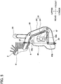
- Fig. 3 is a lateral view of the muffler 20 shown in Fig. 1 .
- the muffler 20 is mainly constituted by the connection duct 21, the branch pipe 30, the expansion chamber 40 and the exhaust outlet 47.
- the exhaust gas discharged from the exhaust port 8 of the engine 2 flows into the connection duct 21 having a U-shape when viewed from the lateral side.
- the connection duct 21 connects the exhaust port 8 of the engine 2 and an inlet opening (which will be described later) of the expansion chamber 40.
- the connection duct 21 extends downward in such a manner that it is separated from the engine 2 and becomes distanced from an extension line of an axis 8a of the exhaust port 8.
- a flange 28 is provided at an inlet side (which will be described later) of the expansion chamber 40 in such a manner that the flange 28 faces an engine block such as the crank case 9.
- a flange 27 (first flange) is fixed to the cylinder 3 of the engine 2 by two bolts (not shown), and the flange 28 (second flange) is fixed to the expansion chamber 40 by two bolts (not shown).
- the expansion chamber 40 provides a predetermined internal space for the purpose of reducing exhaust noise and is disposed at an inner side of the cylinder 3, the crank case 9 and the connection duct 21. That is, the expansion chamber 40 is disposed at a limited space defined by the cylinder 3, the crank case 9 and the connection duct 21.
- the expansion chamber 40 is formed as a single closed space having one opening (inlet) and one discharging hole (outlet). The opening as the inlet is placed with the flange 28 and the exhaust outlet 47 that guides exhaust gas to a particular direction is connected to the vicinity of the discharging hole as the outlet.
- the expansion chamber 40 has protuberant walls at the front and rear sides of a plate member 41 as a base, and a front side chamber 44 and a rear side chamber 42 are formed. As a result, a housing for defining the expansion chamber 40 is formed. Since the rear side chamber 42 has a shape following a shape of the crank case 9 of the engine 2, thickness (front-rear length) d2 of a lower part 42b thereof is larger than thickness (front-rear length) d1 of an upper part 42a thereof, thereby securing a volume of the expansion chamber as much as possible in a limited space.
- connection duct 21 is provided at the outside of the expansion chamber 40 to surround the expansion chamber 40, and is bent into an U-shape having an open end toward the crank case 9 when viewed from the lateral side as shown in Fig. 3 .
- the exhaust outlet 47 is connected to the vicinity of the discharging hole (which will be described later) of the expansion chamber 40, and is formed by pressing a metal plate.
- the exhaust outlet 47 is fixed to the expansion chamber 40 by two screws 49. Since the connection duct 21 is connected to extend along the axial direction of the exhaust port 8, passage resistance to the exhaust gas can be as small as possible, which may result in a sufficient exhaust pulsation effect.
- the branch pipe 30 having one end which is closed and another end which is opened is connected to the middle of the connection duct 21. Accordingly, a pressing member 31 as a fixing member that fixes the end of the branch pipe 30 is attached to the lateral side of the expansion chamber 40.
- Such arrangement of the branch pipe 30 is to synchronize a pressure wave at a normal rotational speed of 8,000 rpm to 9,000 rpm.
- Fig. 4 is a lateral view of the expansion chamber 40 of the muffler 20. Shapes of the front side chamber 44 and the rear side chamber 42 of the expansion chamber 40 is shown in Fig. 4 .
- the closed space of the expansion chamber 40 is formed by forming the front side chamber 44 and the rear side chamber 42 by pressing two metal plates, respectively, and by fitting and bonding a front plate member 41b and a rear plate member 41a, which are residual in the outer periphery of these chambers 44 and 42.
- the front side chamber 44 has a shape following a shape of the inner circumference of the connection duct 21 and thickness (front-rear length) e1 at an upper part thereof is thinner than thickness (front-rear length) e2 at a lower part thereof, thereby securing a volume of the expansion chamber as much as possible in a limited space.
- a wall at the front of the front side chamber 44 is oblique by an angle ⁇ as shown in Fig. 4 .
- This is also a shape following the outer diameter of the rotation blade 11 which is a front end tool, and is suitable for disposing the muffler 20 in the rear of the rotation blade 11.
- Fig. 5 is a cross-sectional view of the muffler 20. It should be noted that the front-rear direction in Fig. 5 is reverse to those in Figs. 1 to 4 because Fig. 5 is a cross-sectional view viewed from the right side.
- the connection duct 21 extends along the periphery of the front side of the expansion chamber 40, and the flange 27 which can be attached to/detached from the cylinder 3 is provided in the end of the upper side of the duct.
- the flange 28 which can be attached to/detached from the expansion chamber 40 is provided in an end of the lower side of the connection duct.
- the flange 27 is fixed to the vicinity of the exhaust port 8 of the cylinder 3 by bolts (not shown).
- the flange 27 is fixed to insert the plate member 41 of the expansion chamber 40.
- the flange 28 is fixed to the rear side chamber 42 by bolts (not shown). Nuts (not shown) to be fixed to the bolts are welded or brazed to the inner circumferential wall of the rear side chamber 42.
- a nut 44c is fixed to the inner wall of the front side chamber 44 by welding or brazing. The nut 44c is to fix a bolt for fixing the pressing member 31 (see Fig. 3 ) that fixes one end of the branch pipe 30.
- connection duct 21 has an exhaust gas passage 25 defined by two members, i.e., a front wall 23 and a rear wall 24.
- the connection duct 21 has a shape following the outer diameter of the front side chamber 44 of the expansion chamber 40, and is mainly formed with two radiuses of curvature R1 and R2 (R1>R2).
- the radius of curvature R1 at a portion of the connection duct 21 closer to the exhaust port 8 is set to be as large as possible in order to prevent exhaust resistance from increasing, while the radius of curvature R2 at a portion of the connection duct 21 closer to the expansion chamber 40 is set to be as large as possible in order to make maximum use of a space between the wheel guard 12 and the engine 2, thereby securing a volume of the front side chamber 44 of the expansion chamber 40 as much as possible.
- the interior of the expansion chamber 40 is a single large space having an opening 43b as an inlet of the expansion chamber 40 and an opening 44b as an outlet thereof.
- the interior of the expansion chamber 40 may not only be configured of a single room but also divided into two partitions, such as a first expansion chamber and a second expansion chamber, or into three or more partitions.
- a catalyst device may be placed in the interior of the expansion chamber 40.
- Fig. 6 is a perspective view of the expansion chamber 40 of the muffler 20.
- the expansion chamber 40 is configured such that the plate member 41 projects toward outside of the periphery between the front side chamber 44 and the rear side chamber 42.
- the plate member 41 corresponds to a residual portion, which is not pressed in press machining of a rectangular metal plate to form the front side chamber 44 and the rear side chamber 42, and is used to bond the front side chamber 44 and the rear side chamber 42.
- the plate member 41 appears to be a single member in the perspective view of Fig. 6
- the plate member 41 is formed with two metal plate members, i.e., the front plate member 41b integrated with the front side chamber 44 and the rear plate member 41 a integrated with the rear side chamber 42.
- the rear plate member 41 a is larger in size than the front plate member 41b, and is joined to the front plate member 41b by bending the periphery of the rear plate member 41a to fit into the periphery of the front plate member 41b.
- An opening 43a for introducing exhaust gas from the exhaust port 8 of the engine 2 into the connection duct 21 is formed to the upper part of the plate member 41.
- the opening 43a has an approximately rectangular shape horizontally widened along the internal shape of the exhaust port 8 and the connection duct 21.
- the opening 43a is not limited thereto but may have a square shape or other shapes.
- Two screw holes 43c (first screw holes) through which bolts for fixing the flange 27 pass are formed in both left and right side of the opening 43a. Bolts (not shown) inserted from the flange 27 side pass through the two screw holes 43c and are joined to screw holes formed in the cylinder 3 of the engine 2.
- An opening 43b for introducing exhaust gas discharged from the connection duct 21 into the expansion chamber 40 is formed in the lower part of the plate member 41.
- Two screw holes 43d (second screw holes) through which bolts for fixing the flange 28 pass are formed at both left and right sides of the opening 43b.
- Screw holes 43e (third screw holes) through which bolts for fixing the expansion chamber 40 to the crank case 9 pass are formed it both outer sides of the screw holes 43d.
- bolts (not shown) in the flange 28 are fixed to the expansion chamber 40.
- Nuts (not shown) are fixed in the back side of the screw holes 43d by welding or the like.
- the reason why the flange 28 and the plate member 41 are not directly fixed to the engine block such as the crank case 9 is to prevent the expansion chamber 40 from being loosened by vibration of the engine 2 to alleviate a possibility of leakage of the exhaust gas around the opening 43b.
- the expansion chamber 40 to the crank case 9 by bolts at a separate portion apart from the flange 28, drop-out by engine vibration can be more effectively prevented to provide more resistance to high power of the engine 2.
- screws and bolts are not differentiated from each other, and are almost synonymous with each other in terms of a joining member. As long as a joining means having a male portion and a female portion which are fixed to each other, any of screws, bolts and other means may be taken.
- a screw hole 44a (fourth screw hole) for fixing the pressing member 31 is formed in the lateral side of the front side chamber 44.
- nut 44c In the inner wall of the screw hole 44a, nut 44c (see Fig. 5 ) are fixed to the front side chamber 44 by welding or the like.
- the exhaust outlet 47 is also formed in the lateral side of the front side chamber 44. The exhaust outlet 47 covers the surroundings of the opening 44b (see Fig. 5 ), and guides the discharged exhaust gas in a predetermined direction.
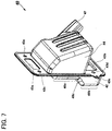
- Fig. 7 is a perspective view of the expansion chamber 40 of the muffler 20 when viewed from a different angle. Since a portion of the rear side chamber 42, denoted by reference numeral 48a, corresponds to a portion where the crank case 9 of the engine 2 is located, front-rear length (thickness) thereof is set to be relatively small. This is to prevent the expansion chamber 40 from excessively projecting to the front of the engine 2. Meanwhile, since a portion denoted by reference numeral 48b corresponds to a lower part of the crank case 9 to provide a relatively large space, front-rear length (thickness) thereof is set to be relatively large, thereby securing a volume of the expansion chamber 40. A portion indicated by an arrow 48c in the middle portion between the portion 48a and the portion 48b is formed to be oblique along the shape of the crank case 9.
- Fig. 8 is an exploded view illustrating an assembly structure of the connection duct 21 and the branch pipe 30.
- the connection duct 21 is constituted by two members, i.e., the front wall 23 and the rear wall 24.
- the front wall 23 and the rear wall 24 are formed by press machining a metal plate, respectively.
- the front wall 23 is pressed to have a U-shape when viewed from the lateral side such that ear portions 23b are formed in both peripheries of the inner circumference of the front wall 23.
- the rear wall 24 is bent into a shape along the peripheries of the inner circumference of the front wall 23, thereby forming bent portions 24a, 24b and 24c for fixing the ear portions 23b therebetween.
- the bent portions 24a to 24c are difficult.
- the bent portions 24a to 24c cannot be formed to a curved surface of the rear wall 24.
- the front wall 23 and the rear wall 24 are fixed to a curved surface 24d or the like where the bent portions 24a to 24c are not formed, by means of brazing or welding.
- the flange 27 is joined to the upper opening and the flange 28 is joined to the lower opening.
- These flanges 27 and 28 may be fixed by welding, brazing, adhesion or the like.
- Such arrangement of the flanges 27 and 28 facilitates joining and fixing of the cylinder 3, the crank case 9 and the expansion chamber 40, which may result in prevention of the connection duct 21 from being damaged due to vibration of the engine 2.
- a through hole 23a for connecting the U-shaped branch pipe 30 is formed in a portion of the front wall 23.
- the branch pipe 30 has one opened end 30a to be connected to the through hole 23a and the other closed end 30b.
- the through hole 23a is formed to have a tubular shape to extend to the interior of the opened end 30a and the branch pipe 30 is inserted in and fixed to the tubular through hole 23a.
- the branch pipe 30 is preferably fixed to the front wall 23 by welding or brazing.
- the other end, i.e., the closed end 30b, of the branch pipe 30 is inserted in a cylindrical concave portion 31a of the pressing member 31, and the pressing member 31 is fixed to the lateral side of the front side chamber 44.
- connection duct 21 The reason for the divisional configuration of the connection duct 21 as shown in Fig. 8 is to form a passage of the connection duct 21 at a low cost, improve air-tightness of the passage and achieve a reliable pressure pulsation effect by joining two-divided plate members by caulking, welding or brazing.
- the expansion chamber 40 when the expansion chamber 40 is commonalized, the expansion chamber 40 can be applied to a number of tuning revolution of pulsation or different engine displacements only by changing length or sectional area of the connection duct 21 and the branch pipe 30, which may result in decrease in cost of the expansion chamber 40.
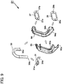
- the second exemplary embodiment provides a connection duct 51 different from that of the first exemplary embodiment.
- the connection duct 51 is vertically divided into two parts, i.e., a left part 53 and a right part 54, in an axial direction of the exhaust port 8 and in a plane perpendicular to the crank shaft 16.
- the left part 53 and the right part 54 are joined to each other by caulking, welding or brazing.
- the present exemplary embodiment employs caulking for such joining.
- ear portions 54a and 54b are formed in the periphery in the vicinity of a joining portion of the right part 54 and bent portions 53a and 53b are formed in the periphery in the vicinity of a joining portion of the left part 53.
- the bent portions 53a and 53b are bent to insert the ear portions 54a and 54b therebetween, respectively.
- the left part 53 and the right part 54 may be formed at a low cost by press machining of a metal plate and may be joined by caulking.
- the flange 27 is joined to the upper opening and the flange 28 is joined to the lower opening.
- These flanges may be fixed by welding, brazing, adhesion or the like.
- Such arrangement of the flanges 27 and 28 facilitates joining and fixing of the cylinder 3 and the expansion chamber 40, which may result in prevention of the connection duct 51 from being damage due to vibration of the engine 2.
- the semi-cylindrical ear portions 54a and 54b are formed in a portion which is in the vicinity of an upper portion of the left part 53 and the right part 54 and passes a joining plane of the left part 53 and the right part 54, and the opened end 30a of the branch pipe 30 is inserted in and fixed to a cylindrical portion defined by the semi-cylindrical ear portions.
- the branch pipe 30 is preferably fixed to the cylindrical portion of the connection duct 51 by welding or brazing.
- the closed end 30b of the branch pipe 30 is inserted in the cylindrical concave portion 31 a of the pressing member 31 and the pressing member 31 is fixed to the side of the front side chamber 44.
- a connection duct 71 is constituted by an outer wall of an expansion chamber 80 and a passage plate member 73. Accordingly, there is no need of a part corresponding to the rear wall 24 of Fig. 8 .
- Ear portions 73b and 73c horizontally widened are formed to the periphery of the passage plate member 73 and are joined to the outer wall of a front side chamber 84 by welding or brazing.
- the passage plate member 73 is fabricated by pressing a metal plate and has substantially the same shape as the front side wall 23 of the first exemplary embodiment, which is U-shape when viewed from the lateral side.
- the expansion chamber 80 has essentially substantially the same shape as the expansion chamber 40 of the first exemplary embodiment. However, since a portion of the outer wall of the front side chamber 84 forms the connection duct, an uneven portion, such as a rib for improvement of strength, is not formed to the outer wall of the front side chamber 84.
- a through hole 73a for connecting the branch pipe 30 is formed in a portion of the passage plate member 73.
- the U-shaped branch pipe 30 is connected to the through hole 73a.
- the branch pipe 30 has one opened end 30a to be connected to the through hole 73a and the other closed end 30b, as in the first exemplary embodiment.
- the through hole 73a is formed to have a tubular shape to extend to the interior of the opened end 30a, and the branch pipe 30 is inserted in and fixed to the tubular through hole 73a.
- the closed end 30b of the branch pipe 30 is inserted in a cylindrical concave portion 31a of the pressing member 31, and the pressing member 31 is fixed to the lateral side (a fixing part is not shown in Fig. 10 ) of the front side chamber 84.
- the passage plate member 73 and the expansion chamber 80 are directly fixed to each other by welding or brazing, the flanges 27 and 28 as shown in Figs. 8 and 9 are not required. Accordingly, by passing bolts (not shown) through screw holes 83c of a plate member 81 and fixing the bolts to female screws formed in the cylinder 3, a muffler 70 is fixed to the cylinder 3 of the engine 2.
- the expansion chamber 80 shown in Fig. 10 has a structure so as not to be fixed to the crank case 9 of the engine 2 in the vicinity of a lower part thereof, the expansion chamber 80 may have a structure so as to be fixed by using the screw holes 43e as shown in Fig. 6 .
- connection duct 71 is formed by fixing the passage plate member 73 to the expansion chamber 80, it is possible to achieve a muffler at a lower fabricating cost of the mold or material compared to forming the connection duct 21 or 51 by using two-divided press members.
- a wheel guard and an arm that holds a power transmission to rotate a blade are formed around a muffler in, for example, an engine cutter that cuts a concrete and so on, thereby limiting height, width and length of an expansion chamber
- a volume of the expansion chamber can be sufficiently secured regardless of the limitation, and length of the connection duct connected to the exhaust port and the expansion chamber can be also sufficiently secured, decreased exhaust gas and high power by pressure pulsation can be obtained.
- the engine-driven work machine has been illustrated with the engine cutter that cuts a concrete and so on, the present invention is not limited thereto but may be applied to other work machines including two-cycle engines as a source of power.
- the front end tool equipped in the engine-driven work machine is not limited to the rotation blade but may use other known tools and working members.
- a compact muffler in which a pressure pulsation effect is not destroyed, and an engine-driven work machine including the muffler.
Landscapes
- Engineering & Computer Science (AREA)
- Chemical & Material Sciences (AREA)
- Combustion & Propulsion (AREA)
- Mechanical Engineering (AREA)
- General Engineering & Computer Science (AREA)
- Exhaust Silencers (AREA)
Applications Claiming Priority (2)
| Application Number | Priority Date | Filing Date | Title |
|---|---|---|---|
| JP2011067535A JP5765528B2 (ja) | 2011-03-25 | 2011-03-25 | マフラー及びエンジン作業機 |
| PCT/JP2012/057255 WO2012133071A1 (en) | 2011-03-25 | 2012-03-14 | Muffler and engine-driven work machine |
Publications (2)
| Publication Number | Publication Date |
|---|---|
| EP2689114A1 EP2689114A1 (en) | 2014-01-29 |
| EP2689114B1 true EP2689114B1 (en) | 2016-07-20 |
Family
ID=45937513
Family Applications (1)
| Application Number | Title | Priority Date | Filing Date |
|---|---|---|---|
| EP12713387.4A Not-in-force EP2689114B1 (en) | 2011-03-25 | 2012-03-14 | Engine-driven work machine |
Country Status (8)
| Country | Link |
|---|---|
| US (1) | US9200558B2 (https=) |
| EP (1) | EP2689114B1 (https=) |
| JP (1) | JP5765528B2 (https=) |
| CN (1) | CN103443410B (https=) |
| AU (1) | AU2012234623B2 (https=) |
| BR (1) | BR112013024648A2 (https=) |
| RU (1) | RU2606549C2 (https=) |
| WO (1) | WO2012133071A1 (https=) |
Families Citing this family (3)
| Publication number | Priority date | Publication date | Assignee | Title |
|---|---|---|---|---|
| JP6236944B2 (ja) * | 2012-11-10 | 2017-11-29 | 日立工機株式会社 | マフラー及びエンジン作業機 |
| JP6401651B2 (ja) * | 2015-04-15 | 2018-10-10 | 株式会社やまびこ | 動力作業機 |
| US11694876B2 (en) | 2021-12-08 | 2023-07-04 | Applied Materials, Inc. | Apparatus and method for delivering a plurality of waveform signals during plasma processing |
Family Cites Families (27)
| Publication number | Priority date | Publication date | Assignee | Title |
|---|---|---|---|---|
| US3665712A (en) * | 1970-02-09 | 1972-05-30 | William L Tenney | Two-cycle engine resonance exhaust system |
| US3842599A (en) * | 1972-12-18 | 1974-10-22 | Mcculloch Corp | Exhaust system for a two-cycle engine |
| JPS5167934U (https=) * | 1974-11-22 | 1976-05-29 | ||
| DE2643242B2 (de) * | 1976-09-25 | 1978-12-14 | Fa. J. Eberspaecher, 7300 Esslingen | Kleinschalldämpfer, insbesondere für Baumsägemotoren |
| US4290501A (en) * | 1979-01-19 | 1981-09-22 | Yamaha Hatsudoki Kabushiki Kaisha | Exhaust silencer, especially for small vehicles |
| SU1280138A2 (ru) * | 1979-10-17 | 1986-12-30 | Центральный Научно-Исследовательский И Проектно-Конструкторский Институт Механизации И Энергетики Лесной Промышленности | Глушитель шума выхлопа двигател внутреннего сгорани |
| EP0145479B1 (en) * | 1983-12-12 | 1988-09-07 | Kawasaki Jukogyo Kabushiki Kaisha | Exhaust control system for 2-cycle engines |
| JPH0192515A (ja) | 1987-09-30 | 1989-04-11 | Honda Motor Co Ltd | 2サイクルエンジンの排気装置 |
| JP2730738B2 (ja) * | 1987-12-08 | 1998-03-25 | アンドレアス シュティール | 2サイクルエンジンの排ガス消音器 |
| AU615389B2 (en) * | 1989-08-30 | 1991-09-26 | Mitsubishi Jukogyo Kabushiki Kaisha | Muffler for industrial engine |
| JPH0533628A (ja) * | 1991-07-26 | 1993-02-09 | Toyota Motor Corp | 排気消音器 |
| SE516698C2 (sv) * | 1996-11-15 | 2002-02-12 | Electrolux Ab | Förbränningsmotor |
| DE19747914A1 (de) * | 1997-10-30 | 1999-05-06 | Stihl Maschf Andreas | Abgasschalldämpfer |
| DE29802099U1 (de) * | 1998-02-07 | 1998-03-26 | Fa. Andreas Stihl, 71336 Waiblingen | Abgasschalldämpfer für einen Zweitaktmotor |
| SE9903403L (sv) * | 1999-09-22 | 2001-03-23 | Electrolux Ab | Tvåtakts förbränningsmotor |
| SE0001465L (sv) * | 2000-04-20 | 2001-10-21 | Electrolux Ab | Ljuddämpare |
| US6959782B2 (en) * | 2002-03-22 | 2005-11-01 | Tecumseh Products Company | Tuned exhaust system for small engines |
| DE10239132B4 (de) * | 2002-08-27 | 2012-11-15 | Andreas Stihl Ag & Co | Abgasschalldämpfer |
| ATE524262T1 (de) * | 2003-12-09 | 2011-09-15 | Husqvarna Ab | Tragbare arbeitsmaschine |
| DE10361216B4 (de) * | 2003-12-24 | 2012-11-15 | Andreas Stihl Ag & Co. Kg | Abgasschalldämpfer |
| DE202006013280U1 (de) * | 2006-08-30 | 2008-02-07 | Dolmar Gmbh | Schalldämpfer mit Kiemenauslass |
| US20100083512A1 (en) * | 2008-10-06 | 2010-04-08 | Husqvarna Zenoah Co., Ltd. | Chain saw |
| JP5539692B2 (ja) | 2009-09-28 | 2014-07-02 | テルモ株式会社 | 操作案内表示装置、操作案内表示システム及び医療機器 |
| JP5678541B2 (ja) * | 2010-09-22 | 2015-03-04 | 日立工機株式会社 | 携帯作業機用2サイクルエンジンおよびそれを備えた携帯作業機 |
| JP2012067669A (ja) * | 2010-09-22 | 2012-04-05 | Hitachi Koki Co Ltd | 携帯作業機用2サイクルエンジンおよびそれを備えた携帯作業機 |
| WO2012120118A1 (de) * | 2011-03-09 | 2012-09-13 | Makita Corporation | Schalldämpfer für ein motorgerät |
| JP6098292B2 (ja) * | 2013-03-28 | 2017-03-22 | 日立工機株式会社 | エンジン及び携帯作業機 |
-
2011
- 2011-03-25 JP JP2011067535A patent/JP5765528B2/ja not_active Expired - Fee Related
-
2012
- 2012-03-14 BR BR112013024648A patent/BR112013024648A2/pt not_active Application Discontinuation
- 2012-03-14 RU RU2013147451A patent/RU2606549C2/ru not_active IP Right Cessation
- 2012-03-14 CN CN201280015137.3A patent/CN103443410B/zh not_active Expired - Fee Related
- 2012-03-14 EP EP12713387.4A patent/EP2689114B1/en not_active Not-in-force
- 2012-03-14 WO PCT/JP2012/057255 patent/WO2012133071A1/en not_active Ceased
- 2012-03-14 US US14/004,306 patent/US9200558B2/en not_active Expired - Fee Related
- 2012-03-14 AU AU2012234623A patent/AU2012234623B2/en not_active Ceased
Also Published As
| Publication number | Publication date |
|---|---|
| US20140000574A1 (en) | 2014-01-02 |
| WO2012133071A1 (en) | 2012-10-04 |
| JP2012202293A (ja) | 2012-10-22 |
| AU2012234623A1 (en) | 2013-10-17 |
| CN103443410B (zh) | 2016-08-17 |
| AU2012234623B2 (en) | 2016-08-04 |
| US9200558B2 (en) | 2015-12-01 |
| BR112013024648A2 (pt) | 2016-12-20 |
| JP5765528B2 (ja) | 2015-08-19 |
| RU2013147451A (ru) | 2015-04-27 |
| CN103443410A (zh) | 2013-12-11 |
| RU2606549C2 (ru) | 2017-01-10 |
| EP2689114A1 (en) | 2014-01-29 |
Similar Documents
| Publication | Publication Date | Title |
|---|---|---|
| EP2933459B1 (en) | Engine supercharger | |
| EP2689114B1 (en) | Engine-driven work machine | |
| JP6498086B2 (ja) | 汎用エンジンのマフラ | |
| TWI359899B (en) | Muffler unit for general-purpose engine | |
| JP2000071181A (ja) | 手で操縦される作業機の駆動ユニット | |
| US5996732A (en) | Muffler for a two-stroke internal combustion engine | |
| JP2012026435A (ja) | 空気掃気型の2サイクルエンジン | |
| CN108603426A (zh) | 发动机及发动机作业机 | |
| JP2017133490A (ja) | エンジン及びエンジン作業機 | |
| JP4391469B2 (ja) | 2サイクルエンジン | |
| JPH09158743A (ja) | ターボチャージャー付排気管の遮熱装置 | |
| JP6236944B2 (ja) | マフラー及びエンジン作業機 | |
| CN100371567C (zh) | 排气消声器 | |
| JP3819591B2 (ja) | 空冷エンジン | |
| US20220290600A1 (en) | Exhaust device of engine and work machine | |
| JP2012202293A5 (https=) | ||
| US7930884B2 (en) | Exhaust manifold | |
| JP3773502B2 (ja) | コンパクトな掃気タンクとシリンダフレームのアセンブリ及びその製造方法 | |
| JP2016223353A (ja) | チェンソー | |
| JP3818494B2 (ja) | 空冷式2サイクルエンジン | |
| JP5527140B2 (ja) | エンジンおよびそれを備えたエンジン作業機 | |
| JP3366371B2 (ja) | 内燃機関 | |
| WO2019082598A1 (ja) | マフラ及びそれを備えたエンジン作業機 | |
| JPH08165923A (ja) | エンジンのマフラ | |
| JP2016070201A (ja) | エンジン作業機 |
Legal Events
| Date | Code | Title | Description |
|---|---|---|---|
| PUAI | Public reference made under article 153(3) epc to a published international application that has entered the european phase |
Free format text: ORIGINAL CODE: 0009012 |
|
| 17P | Request for examination filed |
Effective date: 20130925 |
|
| AK | Designated contracting states |
Kind code of ref document: A1 Designated state(s): AL AT BE BG CH CY CZ DE DK EE ES FI FR GB GR HR HU IE IS IT LI LT LU LV MC MK MT NL NO PL PT RO RS SE SI SK SM TR |
|
| RIN1 | Information on inventor provided before grant (corrected) |
Inventor name: YASUTOMI, TOSHINORI |
|
| DAX | Request for extension of the european patent (deleted) | ||
| 17Q | First examination report despatched |
Effective date: 20150603 |
|
| GRAP | Despatch of communication of intention to grant a patent |
Free format text: ORIGINAL CODE: EPIDOSNIGR1 |
|
| RIC1 | Information provided on ipc code assigned before grant |
Ipc: F01N 1/08 20060101AFI20160126BHEP Ipc: F02B 75/02 20060101ALI20160126BHEP Ipc: F01N 13/08 20100101ALI20160126BHEP Ipc: F01N 13/18 20100101ALI20160126BHEP Ipc: F02B 63/02 20060101ALI20160126BHEP Ipc: F01N 13/00 20100101ALI20160126BHEP Ipc: F02B 27/04 20060101ALI20160126BHEP |
|
| INTG | Intention to grant announced |
Effective date: 20160210 |
|
| GRAS | Grant fee paid |
Free format text: ORIGINAL CODE: EPIDOSNIGR3 |
|
| GRAA | (expected) grant |
Free format text: ORIGINAL CODE: 0009210 |
|
| AK | Designated contracting states |
Kind code of ref document: B1 Designated state(s): AL AT BE BG CH CY CZ DE DK EE ES FI FR GB GR HR HU IE IS IT LI LT LU LV MC MK MT NL NO PL PT RO RS SE SI SK SM TR |
|
| REG | Reference to a national code |
Ref country code: GB Ref legal event code: FG4D |
|
| REG | Reference to a national code |
Ref country code: CH Ref legal event code: EP |
|
| REG | Reference to a national code |
Ref country code: IE Ref legal event code: FG4D |
|
| REG | Reference to a national code |
Ref country code: AT Ref legal event code: REF Ref document number: 814287 Country of ref document: AT Kind code of ref document: T Effective date: 20160815 |
|
| REG | Reference to a national code |
Ref country code: DE Ref legal event code: R096 Ref document number: 602012020689 Country of ref document: DE |
|
| REG | Reference to a national code |
Ref country code: LT Ref legal event code: MG4D |
|
| REG | Reference to a national code |
Ref country code: NL Ref legal event code: MP Effective date: 20160720 |
|
| REG | Reference to a national code |
Ref country code: AT Ref legal event code: MK05 Ref document number: 814287 Country of ref document: AT Kind code of ref document: T Effective date: 20160720 |
|
| PG25 | Lapsed in a contracting state [announced via postgrant information from national office to epo] |
Ref country code: FI Free format text: LAPSE BECAUSE OF FAILURE TO SUBMIT A TRANSLATION OF THE DESCRIPTION OR TO PAY THE FEE WITHIN THE PRESCRIBED TIME-LIMIT Effective date: 20160720 Ref country code: NO Free format text: LAPSE BECAUSE OF FAILURE TO SUBMIT A TRANSLATION OF THE DESCRIPTION OR TO PAY THE FEE WITHIN THE PRESCRIBED TIME-LIMIT Effective date: 20161020 Ref country code: IT Free format text: LAPSE BECAUSE OF FAILURE TO SUBMIT A TRANSLATION OF THE DESCRIPTION OR TO PAY THE FEE WITHIN THE PRESCRIBED TIME-LIMIT Effective date: 20160720 Ref country code: NL Free format text: LAPSE BECAUSE OF FAILURE TO SUBMIT A TRANSLATION OF THE DESCRIPTION OR TO PAY THE FEE WITHIN THE PRESCRIBED TIME-LIMIT Effective date: 20160720 Ref country code: LT Free format text: LAPSE BECAUSE OF FAILURE TO SUBMIT A TRANSLATION OF THE DESCRIPTION OR TO PAY THE FEE WITHIN THE PRESCRIBED TIME-LIMIT Effective date: 20160720 Ref country code: IS Free format text: LAPSE BECAUSE OF FAILURE TO SUBMIT A TRANSLATION OF THE DESCRIPTION OR TO PAY THE FEE WITHIN THE PRESCRIBED TIME-LIMIT Effective date: 20161120 Ref country code: HR Free format text: LAPSE BECAUSE OF FAILURE TO SUBMIT A TRANSLATION OF THE DESCRIPTION OR TO PAY THE FEE WITHIN THE PRESCRIBED TIME-LIMIT Effective date: 20160720 Ref country code: RS Free format text: LAPSE BECAUSE OF FAILURE TO SUBMIT A TRANSLATION OF THE DESCRIPTION OR TO PAY THE FEE WITHIN THE PRESCRIBED TIME-LIMIT Effective date: 20160720 |
|
| REG | Reference to a national code |
Ref country code: FR Ref legal event code: PLFP Year of fee payment: 6 |
|
| PG25 | Lapsed in a contracting state [announced via postgrant information from national office to epo] |
Ref country code: GR Free format text: LAPSE BECAUSE OF FAILURE TO SUBMIT A TRANSLATION OF THE DESCRIPTION OR TO PAY THE FEE WITHIN THE PRESCRIBED TIME-LIMIT Effective date: 20161021 Ref country code: ES Free format text: LAPSE BECAUSE OF FAILURE TO SUBMIT A TRANSLATION OF THE DESCRIPTION OR TO PAY THE FEE WITHIN THE PRESCRIBED TIME-LIMIT Effective date: 20160720 Ref country code: AT Free format text: LAPSE BECAUSE OF FAILURE TO SUBMIT A TRANSLATION OF THE DESCRIPTION OR TO PAY THE FEE WITHIN THE PRESCRIBED TIME-LIMIT Effective date: 20160720 Ref country code: PL Free format text: LAPSE BECAUSE OF FAILURE TO SUBMIT A TRANSLATION OF THE DESCRIPTION OR TO PAY THE FEE WITHIN THE PRESCRIBED TIME-LIMIT Effective date: 20160720 Ref country code: SE Free format text: LAPSE BECAUSE OF FAILURE TO SUBMIT A TRANSLATION OF THE DESCRIPTION OR TO PAY THE FEE WITHIN THE PRESCRIBED TIME-LIMIT Effective date: 20160720 Ref country code: PT Free format text: LAPSE BECAUSE OF FAILURE TO SUBMIT A TRANSLATION OF THE DESCRIPTION OR TO PAY THE FEE WITHIN THE PRESCRIBED TIME-LIMIT Effective date: 20161121 Ref country code: LV Free format text: LAPSE BECAUSE OF FAILURE TO SUBMIT A TRANSLATION OF THE DESCRIPTION OR TO PAY THE FEE WITHIN THE PRESCRIBED TIME-LIMIT Effective date: 20160720 Ref country code: BE Free format text: LAPSE BECAUSE OF FAILURE TO SUBMIT A TRANSLATION OF THE DESCRIPTION OR TO PAY THE FEE WITHIN THE PRESCRIBED TIME-LIMIT Effective date: 20160720 |
|
| REG | Reference to a national code |
Ref country code: DE Ref legal event code: R097 Ref document number: 602012020689 Country of ref document: DE |
|
| PG25 | Lapsed in a contracting state [announced via postgrant information from national office to epo] |
Ref country code: EE Free format text: LAPSE BECAUSE OF FAILURE TO SUBMIT A TRANSLATION OF THE DESCRIPTION OR TO PAY THE FEE WITHIN THE PRESCRIBED TIME-LIMIT Effective date: 20160720 Ref country code: RO Free format text: LAPSE BECAUSE OF FAILURE TO SUBMIT A TRANSLATION OF THE DESCRIPTION OR TO PAY THE FEE WITHIN THE PRESCRIBED TIME-LIMIT Effective date: 20160720 |
|
| PLBE | No opposition filed within time limit |
Free format text: ORIGINAL CODE: 0009261 |
|
| STAA | Information on the status of an ep patent application or granted ep patent |
Free format text: STATUS: NO OPPOSITION FILED WITHIN TIME LIMIT |
|
| PG25 | Lapsed in a contracting state [announced via postgrant information from national office to epo] |
Ref country code: CZ Free format text: LAPSE BECAUSE OF FAILURE TO SUBMIT A TRANSLATION OF THE DESCRIPTION OR TO PAY THE FEE WITHIN THE PRESCRIBED TIME-LIMIT Effective date: 20160720 Ref country code: BG Free format text: LAPSE BECAUSE OF FAILURE TO SUBMIT A TRANSLATION OF THE DESCRIPTION OR TO PAY THE FEE WITHIN THE PRESCRIBED TIME-LIMIT Effective date: 20161020 Ref country code: SK Free format text: LAPSE BECAUSE OF FAILURE TO SUBMIT A TRANSLATION OF THE DESCRIPTION OR TO PAY THE FEE WITHIN THE PRESCRIBED TIME-LIMIT Effective date: 20160720 Ref country code: DK Free format text: LAPSE BECAUSE OF FAILURE TO SUBMIT A TRANSLATION OF THE DESCRIPTION OR TO PAY THE FEE WITHIN THE PRESCRIBED TIME-LIMIT Effective date: 20160720 Ref country code: SM Free format text: LAPSE BECAUSE OF FAILURE TO SUBMIT A TRANSLATION OF THE DESCRIPTION OR TO PAY THE FEE WITHIN THE PRESCRIBED TIME-LIMIT Effective date: 20160720 |
|
| 26N | No opposition filed |
Effective date: 20170421 |
|
| PG25 | Lapsed in a contracting state [announced via postgrant information from national office to epo] |
Ref country code: SI Free format text: LAPSE BECAUSE OF FAILURE TO SUBMIT A TRANSLATION OF THE DESCRIPTION OR TO PAY THE FEE WITHIN THE PRESCRIBED TIME-LIMIT Effective date: 20160720 |
|
| REG | Reference to a national code |
Ref country code: CH Ref legal event code: PL |
|
| PG25 | Lapsed in a contracting state [announced via postgrant information from national office to epo] |
Ref country code: MC Free format text: LAPSE BECAUSE OF FAILURE TO SUBMIT A TRANSLATION OF THE DESCRIPTION OR TO PAY THE FEE WITHIN THE PRESCRIBED TIME-LIMIT Effective date: 20160720 |
|
| REG | Reference to a national code |
Ref country code: IE Ref legal event code: MM4A |
|
| PG25 | Lapsed in a contracting state [announced via postgrant information from national office to epo] |
Ref country code: LU Free format text: LAPSE BECAUSE OF NON-PAYMENT OF DUE FEES Effective date: 20170314 |
|
| REG | Reference to a national code |
Ref country code: FR Ref legal event code: PLFP Year of fee payment: 7 |
|
| PG25 | Lapsed in a contracting state [announced via postgrant information from national office to epo] |
Ref country code: CH Free format text: LAPSE BECAUSE OF NON-PAYMENT OF DUE FEES Effective date: 20170331 Ref country code: IE Free format text: LAPSE BECAUSE OF NON-PAYMENT OF DUE FEES Effective date: 20170314 Ref country code: LI Free format text: LAPSE BECAUSE OF NON-PAYMENT OF DUE FEES Effective date: 20170331 |
|
| REG | Reference to a national code |
Ref country code: DE Ref legal event code: R081 Ref document number: 602012020689 Country of ref document: DE Owner name: KOKI HOLDINGS CO., LTD., JP Free format text: FORMER OWNER: HITACHI KOKI CO., LTD., TOKYO, JP |
|
| REG | Reference to a national code |
Ref country code: DE Ref legal event code: R084 Ref document number: 602012020689 Country of ref document: DE |
|
| PG25 | Lapsed in a contracting state [announced via postgrant information from national office to epo] |
Ref country code: MT Free format text: LAPSE BECAUSE OF NON-PAYMENT OF DUE FEES Effective date: 20170314 |
|
| PG25 | Lapsed in a contracting state [announced via postgrant information from national office to epo] |
Ref country code: AL Free format text: LAPSE BECAUSE OF FAILURE TO SUBMIT A TRANSLATION OF THE DESCRIPTION OR TO PAY THE FEE WITHIN THE PRESCRIBED TIME-LIMIT Effective date: 20160720 |
|
| REG | Reference to a national code |
Ref country code: GB Ref legal event code: 746 Effective date: 20181031 |
|
| PG25 | Lapsed in a contracting state [announced via postgrant information from national office to epo] |
Ref country code: HU Free format text: LAPSE BECAUSE OF FAILURE TO SUBMIT A TRANSLATION OF THE DESCRIPTION OR TO PAY THE FEE WITHIN THE PRESCRIBED TIME-LIMIT; INVALID AB INITIO Effective date: 20120314 |
|
| PG25 | Lapsed in a contracting state [announced via postgrant information from national office to epo] |
Ref country code: CY Free format text: LAPSE BECAUSE OF NON-PAYMENT OF DUE FEES Effective date: 20160720 |
|
| PG25 | Lapsed in a contracting state [announced via postgrant information from national office to epo] |
Ref country code: MK Free format text: LAPSE BECAUSE OF FAILURE TO SUBMIT A TRANSLATION OF THE DESCRIPTION OR TO PAY THE FEE WITHIN THE PRESCRIBED TIME-LIMIT Effective date: 20160720 |
|
| PG25 | Lapsed in a contracting state [announced via postgrant information from national office to epo] |
Ref country code: TR Free format text: LAPSE BECAUSE OF FAILURE TO SUBMIT A TRANSLATION OF THE DESCRIPTION OR TO PAY THE FEE WITHIN THE PRESCRIBED TIME-LIMIT Effective date: 20160720 |
|
| PGFP | Annual fee paid to national office [announced via postgrant information from national office to epo] |
Ref country code: GB Payment date: 20220321 Year of fee payment: 11 Ref country code: DE Payment date: 20220322 Year of fee payment: 11 |
|
| PGFP | Annual fee paid to national office [announced via postgrant information from national office to epo] |
Ref country code: FR Payment date: 20220322 Year of fee payment: 11 |
|
| REG | Reference to a national code |
Ref country code: DE Ref legal event code: R119 Ref document number: 602012020689 Country of ref document: DE |
|
| GBPC | Gb: european patent ceased through non-payment of renewal fee |
Effective date: 20230314 |
|
| PG25 | Lapsed in a contracting state [announced via postgrant information from national office to epo] |
Ref country code: GB Free format text: LAPSE BECAUSE OF NON-PAYMENT OF DUE FEES Effective date: 20230314 |
|
| PG25 | Lapsed in a contracting state [announced via postgrant information from national office to epo] |
Ref country code: GB Free format text: LAPSE BECAUSE OF NON-PAYMENT OF DUE FEES Effective date: 20230314 Ref country code: FR Free format text: LAPSE BECAUSE OF NON-PAYMENT OF DUE FEES Effective date: 20230331 Ref country code: DE Free format text: LAPSE BECAUSE OF NON-PAYMENT OF DUE FEES Effective date: 20231003 |