EP2684005B1 - Verstellvorrichtung zum verstellen der abseheneinrichtung eines zielfernrohrs - Google Patents
Verstellvorrichtung zum verstellen der abseheneinrichtung eines zielfernrohrs Download PDFInfo
- Publication number
- EP2684005B1 EP2684005B1 EP20110720012 EP11720012A EP2684005B1 EP 2684005 B1 EP2684005 B1 EP 2684005B1 EP 20110720012 EP20110720012 EP 20110720012 EP 11720012 A EP11720012 A EP 11720012A EP 2684005 B1 EP2684005 B1 EP 2684005B1
- Authority
- EP
- European Patent Office
- Prior art keywords
- index ring
- scale values
- adjusting device
- ring
- revolution
- Prior art date
- Legal status (The legal status is an assumption and is not a legal conclusion. Google has not performed a legal analysis and makes no representation as to the accuracy of the status listed.)
- Active
Links
Images


Classifications
-
- G—PHYSICS
- G02—OPTICS
- G02B—OPTICAL ELEMENTS, SYSTEMS OR APPARATUS
- G02B27/00—Optical systems or apparatus not provided for by any of the groups G02B1/00 - G02B26/00, G02B30/00
- G02B27/32—Fiducial marks and measuring scales within the optical system
- G02B27/36—Fiducial marks and measuring scales within the optical system adjustable
-
- F—MECHANICAL ENGINEERING; LIGHTING; HEATING; WEAPONS; BLASTING
- F41—WEAPONS
- F41G—WEAPON SIGHTS; AIMING
- F41G1/00—Sighting devices
- F41G1/38—Telescopic sights specially adapted for smallarms or ordnance; Supports or mountings therefor
Definitions
- the invention relates to an adjusting device for adjusting the reticle device of a telescopic sight with the further features of the preamble of patent claim 1.
- An adjusting device which serves for adjusting a reticle of a telescopic sight.
- the overall tower-like adjusting device has a rotatable adjusting cap, which is coupled via a transmission device to the reticle within the telescopic sight to implement the rotational movement of the adjusting cap in an adjustment movement of the reticle, which is usually linear.
- Such adjusting devices are used to adjust the reticle to different firing distances.
- the range of rotation of the adjusting cap is designed for more than one revolution, ie it comprises approximately two full revolutions.
- the user has the opportunity to read the rotational position of the adjusting cap and thus the adjustment of the reticle to the firing distance on the basis of scale values, which are assigned to the respective rotational ranges.
- An orbiting set of scale values is associated with the first revolution of the adjustment cap, and a second set of scale values disposed above or below the first set is associated with the second revolution region of the adjustment cap.
- the known adjusting device In the known adjusting device, both sets of scale values are always visible. In order for the user to decide which set of scale values will depend on the position of the adjustment cap within a first or second rotation range of the applicable, the known device comprises a tactile indicating means which protrudes from the adjustment device when the adjustment cap is adjusted within the second rotation range ,
- the invention has for its object to form an adjustment with the features of the preamble of claim 1 such that the clarity in the reading of the scale values is improved and the user is supported in terms of error prevention.
- This object is solved by the characterizing features of claim 1, advantageous developments of the invention will become apparent from the dependent claims.
- At least one index ring carrying the scale values and / or an aperture ring partially covering an index ring region is vertically displaceable such that during the first rotation of the adjustment cap only a first set of the scale values is visible and during the second revolution of the adjusting cap or preferably only the second set of scale values is visible.
- a first option is to arrange the first set of scale values on a first index ring and the second set of scale values on a second index ring located within the first index ring, and the first, d. H. outer index ring, offset in height at the transition from the first rotational range of the adjustment cap to the second range of rotation so that the scale values on the second index ring are covered before the height displacement (first rotation range) and only the scale values on the first outer index ring are visible and after the height displacement, d. H. within the second rotation range, looking at scale values located on the second indexing ring is enabled by the first indexing ring and the scale values located on the first indexing ring vanish below an aperture area. It is possible to shift the outer index ring either up or down and provide either the top or bottom of the covering aperture area for the first scale values on the outer index ring.
- first scale values and the second ones Scale values together with at least one bar scale, which may be arranged between the first and second scale values, for example, to provide only one index ring and this shift up or down depending on the range of rotation within a transition region such that once the first set of scale values is covered and alternatively, the second set of scale values is then covered and the other is visible.
- index ring with the two sets of scale values not ably arranged with the two sets of scale values not ably arranged with the two sets of scale values not ably arranged with the two sets of scale values not ably arranged with the two sets of scale values not ably arranged with the two sets of scale values not ably arranged with the two sets of scale values not ably arranged with the two sets of scale values not ably arranged with the two sets of scale values not ably smallerbar and provide on the outside of the index ring upper and lower annular apertures covering the upper or lower set of scale values on the not Multenverlagerbaren index ring depending on the selected range of rotation.
- a combination of height-adjustable panels and height-adjustable index rings is also conceivable.
- the first set of scale values of the first outer index ring is displaced below a downwardly facing edge of the adjusting cap at the transition from the first revolution to the second revolution of the adjusting cap and thereby covered. Due to the height displacement of the first index ring, the lower edge of the first index ring releases the second set of scale values disposed on the non-height-displaceable second index ring disposed within the first index ring.
- the first and the second index ring - whether they are now hereby HANnverlagerbar or not - synchronously rotated with adjusting cap Corresponding to a setting of the absence scale values can be read off an index mark, which is arranged non-rotatably on a base of the adjusting device.
- the adjustment is a total tower-like structure, the base portion of the tower-like structure is used for attachment to the top of a rifle scope, since such finely adjustable adjusting devices are usually used to make a Ab Spurnver ein, as only through this adaptation to different firing distances is possible.
- a circumferential slotted guide is arranged for the vertical displacement of the index rings or at least one orifice, in the one Plunger dips, which can be coupled via intermediate parts or directly with an index ring or aperture.
- the pin will remain in the slotted guide during the first revolution area without vertical displacement and the coupled index ring thereby maintain its altitude. If the pin passes through further rotation to the sliding guide means region, which has a beveled stepped course, the pin will follow this beveled step-like course and thereby cause the vertical displacement of the index ring or diaphragm ring coupled to it.
- the pin Within the second rotation range, the pin then follows the guide groove of the slotted guide which is essentially parallel to the first rotation region, and then a further height displacement no longer takes place within the second rotation range.
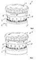
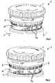
- the adjusting device 1 shown in the drawing figures is used for adjusting the reticle of a not-shown telescopic sight and has a rotatable adjusting cap 2, which is rotatably arranged at the upper end of a total tower-like structure of the adjusting device 1.
- a transmission device 3 is arranged, with which the rotational movement of the adjusting cap 2 is converted into an adjusting movement of the reticle.
- the transmission device 3 is down beyond a base region 4 of the adjusting device 1 addition.
- the range of rotation of the adjusting cap 2 comprises essentially two revolutions, in the central region 5 of the adjusting device 1 two sets of scale values 7 associated with at least one graduated scale 6 are arranged, a first set of scale values 7a indicating adjustment values belonging to the first revolution of the adjusting cap 2 second set of scale values 7b indicates adjustment values belonging to the second revolution of the adjusting cap 2.
- a scale ring 7a carrying, preferably with the adjusting cap 2 synchronously rotatable index ring so essentially arranged under a cover and during the second revolution of the adjusting cap 2, only the associated second set of scale values 7b is visible, the first set of scale values 7a being arranged under a cover.
- Covers may be annular aperture areas, for example, a downwardly depending edge 9 of the adjustment cap 2 located in the region of the upper edge of the index ring 8 and below which edge 9 the first set of scale values 7a dips when the index ring 8 is displaced upwardly ,
- Figure 1-8 is below the in Figures 1 and 2 visible index ring 8
- a second index ring 10 is arranged, which carries the second scale values 7b and which is covered before the switching, ie before the vertical displacement of the index ring 8 from the index ring.
- the first index ring 8 forms, as it were, the cover for the second index ring and the second scale value 7b arranged thereon.
- the height displacement of the first index ring 8 takes place upward, so that the first scale values 7a are brought under the downwardly pointing edge 9 of the adjusting cap. But it is just as possible to shift the outer first index ring when switching from the first to the second rotation range of the adjustment cap down and lower the first scale values 7a below a ring aperture in the region of the base 4.
- a further embodiment lying within the scope of claim 1 provides for arranging both sets of scale values 27a and 27b above and below a graduated scale 26 on an index ring 28.
- This index ring 28 is displaceable upwards and downwards when switching from the first to the second rotation range of the adjusting cap 2, so that once the first index values 27a are visible and once the second index values 27b are visible.
- a further bar scale 26 ' is arranged, which allows a paralax-free reading.
- the index ring 28 is displaced upward during the switching operation, so that the second scale values 27b associated with the second rotation area are selected from one during the first one Turning area concealing lower annular aperture 29 are shifted outwards.
- the lower annular diaphragm 29 forms the upper edge of the base region 4.
- the index ring shown in Figure 10 can also be arranged fixed in terms of its height in the adjustment, the switching then upper and lower apertures, such as the lower annular aperture 29 and an upper annular aperture, as shown in Figure 11, up and shifted down. This also achieves the purpose that only one set of scale values 27a or 27b is visible, so that incorrect settings by the operator of the adjusting device 1 are avoided.
- drawing figure 13 is a perspective view of an inner region of the tower-like structure of the adjusting device 1 is shown.
- a slide guide 40 is rotatably arranged, which has a circumferential slide groove 41 into which a scanning pin 42 (FIG. Fig. 7 ) which engages via coupling elements 43 (cf. FIGS. 7 and 8 ) is coupled to the height-displaceable elements, such as the index ring 8.
- the slide groove 41 has a tapered stage course, so that a scanning pin, the gem in the direction of arrow 45.
- Fig. 13 is brought to the slide guide portion 44, performs an offset movement upwards, which corresponds to the distance between the two circumferential slide grooves 41, whereby it comes to the vertical displacement of the coupled to the pin 42 component, in particular the Multenverlagerbaren index ring 8 or 28.
- an O-ring 50 is provided which seals between the surface of the second index ring 10 and the inside of the first index ring 8.
- Another O-ring 51 seals the upper radially outer region of the first index ring 8 against the inside of the downwardly projecting edge 9 of the adjusting cap 2.
Description
- Die Erfindung betrifft eine Verstellvorrichtung zum Verstellen der Abseheneinrichtung eines Zielfernrohrs mit den weiteren Merkmalen des Oberbegriffs des Patentanspruchs 1.
- Aus
DE 10 2006 016 834 A1 ist eine Verstellvorrichtung bekannt, die zum Verstellen einer Abseheneinrichtung eines Zielfernrohrs dient. Die insgesamt turmartig aufgebaute Verstellvorrichtung weist eine drehbare Einstellkappe auf, die über eine Übertragungseinrichtung an das Absehen innerhalb des Zielfernrohrs gekoppelt ist, um die Drehbewegung der Einstellkappe in eine Verstellbewegung des Absehens umzusetzen, die in der Regel linear ist. Derartige Verstellvorrichtungen dienen dazu, das Absehen an unterschiedliche Schussentfernungen anzupassen. Um eine möglichst feinfühlige Verstellung und damit ein exaktes Schussergebnis sicherzustellen, ist bei der bekannten Vorrichtung der Drehbereich der Einstellkappe für mehr als eine Umdrehung ausgelegt, d. h. er umfasst annähernd zwei volle Umdrehungen. Der Benutzer hat die Möglichkeit, die Drehposition der Einstellkappe und damit die Anpassung des Absehens an die Schussentfernung anhand von Skalenwerten abzulesen, die den jeweiligen Drehbereichen zugeordnet sind. Ein umlaufender Satz von Skalenwerten ist zur ersten Umdrehung bzw. zu einem ersten Umdrehungsbereich der Einstellkappe zugehörig, ein zweiter Satz von Skalenwerten, der über oder unter dem ersten Satz angeordnet ist, ist zum zweiten Umdrehungsbereich der Einstellkappe zugehörig. - Bei der bekannten Stellvorrichtung sind immer beide Sätze von Skalenwerten sichtbar. Damit der Benutzer entscheiden kann, welcher Satz von Skalenwerten abhängig von der Stellung der Einstellkappe innerhalb eines ersten oder zweiten Drehbereichs der Zutreffende ist, weist die bekannte Vorrichtung ein ertastbares Anzeigemittel auf, das aus der Verstellvorrichtung heraussteht, wenn die Einstellkappe innerhalb des zweiten Drehbereichs eingestellt ist.
- Alternativ ist bei der Druckschrift nach dem Stand der Technik noch vorgesehen, eine zweite fühlbare Rasterung bei der Einstellkappe vorzusehen, die durch zweite Rastmittel gebildet wird, wenn die Drehstellung der Einstellkappe innerhalb des zweiten Drehbereichs vorliegt. Nachteilig bei diesen bekannten Einstellvorrichtungen ist, dass es trotz der getroffenen Maßnahmen zur Verwechslungen zwischen den beiden immer sichtbaren Skalenwerten kommen kann.
- Der Erfindung liegt die Aufgabe zugrunde, eine Verstellvorrichtung mit den Merkmalen des Oberbegriffs des Anspruchs 1 derart auszubilden, dass die Übersichtlichkeit bei der Ablesung der Skalenwerte verbessert ist und der Benutzer hinsichtlich einer Fehlervermeidung unterstützt wird. Diese Aufgabe wird durch die kennzeichnenden Merkmale des Anspruchs 1 gelöst, vorteilhafte Weiterbildungen der Erfindung ergeben sich aus den Unteransprüchen.
- Nach der Erfindung ist vorgesehen, dass beim Übergang von dem ersten Umdrehungsbereich zum zweiten Umdrehungsbereich der Einstellkappe wenigstens ein die Skalenwerte tragender Indexring und/oder ein einen Indexringbereich bereichsweise abdeckender Blendenring derart höhenverlagerbar ist, dass während der ersten Umdrehung der Einstellkappe nur ein erster Satz der Skalenwerte sichtbar ist und während der zweiten Umdrehung der Einstellkappe auch oder vorzugsweise nur der zweite Satz von Skalenwerten sichtbar ist.
- Um dies zu verwirklichen, sind unterschiedliche mechanische Möglichkeiten gegeben. Eine erste Möglichkeit besteht darin, den ersten Satz von Skalenwerten auf einem ersten Indexring und den zweiten Satz von Skalenwerte auf einem innerhalb des ersten Indexrings angeordneten zweiten Indexring anzuordnen und den ersten, d. h. äußeren Indexring, beim Übergang vom ersten Drehbewegungsbereich der Einstellkappe zum zweiten Drehbewegungsbereich derart höhenzuverlagern, dass vor der Höhenverlagerung (erster Drehbereich) die Skalenwerte auf dem zweiten Indexring abgedeckt sind und nur die Skalenwerte auf dem ersten äußeren Indexring sichtbar sind und nach der Höhenverlagerung, d. h. innerhalb des zweiten Drehbewegungsbereichs der Blick auf Skalenwerte, die auf dem zweiten Indexring angeordnet sind, durch den ersten Indexring freigegeben wird und die auf dem ersten Indexring angeordneten Skalenwerte unter einem Blendenbereich verschwinden. Dabei ist es möglich, den äußeren Indexring entweder nach oben oder nach unten zu verlagern und entweder oben oder unten den abdeckenden Blendenbereich für die ersten Skalenwerte auf dem äußeren Indexring vorzusehen.
- Eine weitere Möglichkeit besteht darin, sowohl die ersten Skalenwerte als auch die zweiten Skalenwerte zusammen mit wenigstens einer Strichskala, die beispielsweise zwischen den ersten und zweiten Skalenwerten angeordnet sein kann, auf nur einem Indexring vorzusehen und diesen abhängig von dem Drehbereich innerhalb eines Übergangsbereichs derart nach oben oder unten zu verlagern, dass einmal der erste Satz von Skalenwerten abgedeckt wird und alternativ dann der zweite Satz von Skalenwerten abgedeckt wird und der andere sichtbar ist.
- Eine weitere Möglichkeit besteht darin, den Indexring mit den beiden Sätzen von Skalenwerten nicht höhenverlagerbar anzuordnen und auf der Außenseite des Indexrings obere und untere Ringblenden vorzusehen, die abhängig vom gewählten Drehbereich den oberen oder unteren Satz von Skalenwerten auf dem nicht höhenverlagerbaren Indexring abdecken. Auch eine Kombination von höhenverlagerbaren Blenden und höhenverlagerbaren Indexringen ist denkbar.
- Bei einem bevorzugten Ausführungsbeispiel wird der erste Satz von Skalenwerten des ersten äußeren Indexrings beim Übergang von der ersten Umdrehung zur zweiten Umdrehung der Einstellkappe unter einen nach unten weisenden Rand der Einstellkappe verlagert und dadurch abgedeckt. Durch die Höhenverlagerung des ersten Indexrings gibt die Unterkante des ersten Indexrings den zweiten Satz von Skalenwerten frei, die auf dem innerhalb des ersten Indexrings angeordneten nicht höhenverlagerbaren zweiten Indexring angeordnet sind.
- Grundsätzlich werden der erste und der zweite Indexring - ob diese nun höhenverlagerbar sind oder nicht - mit Einstellkappe synchron verdreht. Einer Einstellung des Absehens entsprechende Skalenwerte können anhand einer Indexmarke abgelesen werden, die unverdrehbar an einem Sockel der Verstellvorrichtung angeordnet ist. Die Verstellvorrichtung ist insgesamt turmartig aufgebaut, der Sockelbereich des turmartigen Aufbaus dient zur Befestigung an der Oberseite eines Zielfernrohrs, da derartig feinverstellbare Verstellvorrichtungen in der Regel dazu benutzt werden, eine Absehenhöhenverstellung vorzunehmen, da nur durch diese eine Adaption an unterschiedliche Schussentfernungen möglich ist.
- Im Innenbereich der Verstellvorrichtung ist zur Höhenverlagerung des oder der Indexringe oder der wenigstens einen Blende eine umlaufende Kulissenführung angeordnet, in die ein Abtaststift eintaucht, der über Zwischenteile oder direkt mit einem Indexring oder einer Blende gekoppelt sein kann. Je nach Drehstellung wird der Stift in der Kulissenführung während des ersten Umdrehungsbereichs ohne Höhenverlagerung verbleiben und der daran angekoppelte Indexring dadurch seine Höhenlage beibehalten. Ist der Stift durch Weiterdrehung zum Kulissenführungsmittelbereich gelangt, der einen abgeschrägt stufigen Verlauf aufweist, wird der Stift diesem abgeschrägt stufigen Verlauf folgen und dadurch die Höhenverlagerung des an ihn angekoppelten Indexrings oder Blendenrings verursachen. Innerhalb des zweiten Umdrehungsbereichs folgt dann der Stift der zum ersten Umdrehungsbereich im Wesentlichen parallelen Führungsnut der Kulissenführung, eine weitere Höhenverlagerung erfolgt innerhalb des zweiten Umdrehungsbereichs dann nicht mehr.
- Die Erfindung ist anhand von Ausführungsbeispielen in den Zeichnungsfiguren näher erläutert. Diese zeigen
- Fig. 1
- eine perspektivische Ansicht der erfindungsgemäßen Verstellvorrichtung;
- Fig. 2
- eine Seitenansicht der Verstellvorrichtung gem.
Fig. 1 ; - Fig. 3
- eine Detail-Seitenansicht vor Einleitung einer Verstell-Drehbewegung über den ersten Drehbereich;
- Fig. 4
- eine Darstellung gem.
Fig. 3 , wobei der erste Drehbereich annähernd durchlaufen ist; - Fig. 5
- eine Darstellung gem.
Fig. 4 , wobei eine Weiterdrehung in den Bereich einer Umschaltung zwischen den Skalen erfolgt; - Fig. 6
- eine Darstellung gem.
Fig. 5 , wobei die Drehbewegung so weitergeführt ist, dass nur noch Skalenwerte des zweiten Drehbereichs sichtbar sind; - Fig. 7
- einen mittigen Vertikalschnitt durch die Verstellvorrichtung, wobei eine Skalendarstellung gem.
Fig. 3 sichtbar ist; - Fig. 8
- einen Schnitt gem.
Fig. 7 nach Umschaltung, wobei eine Skalendarstellung gem.Fig. 6 sichtbar ist; - Fig. 9
- eine Darstellung der beiden Indexringe und der Verstellkappe nach Art einer Explosionszeichnung;
- Fig. 10
- eine alternative Ausführungsform eines Indexrings mit zwei alternativ abdeckbaren Skalenwertereihen;
- Fig. 11
- eine modifizierte Ausführungsform mit einer Skalenscheibe gem.
Fig. 10 in einer ersten Drehstellung; - Fig. 12
- eine Darstellung gem.
Fig. 11 in einer modifizierten Drehstellung; - Fig. 13
- eine Darstellung einer Kulissenführung innerhalb der Verstellvorrichtung.
- Die in den Zeichnungsfiguren dargestellte Verstellvorrichtung 1 dient zum Verstellen der Abseheneinrichtung eines nicht näher dargestellten Zielfernrohrs und weist eine drehbare Einstellkappe 2 auf, die am oberen Ende eines insgesamt turmartigen Aufbaus der Verstellvorrichtung 1 drehbar angeordnet ist.
- Im Inneren der Verstellvorrichtung 1 ist eine Übertragungseinrichtung 3 angeordnet, mit der die Drehbewegung der Einstellkappe 2 in eine Verstellbewegung des Absehens umgesetzt wird. Die Übertragungseinrichtung 3 steht nach unten über einen Sockelbereich 4 der Verstellvorrichtung 1 hinaus.
- Der Drehbereich der Einstellkappe 2 umfasst im Wesentlichen zwei Umdrehungen, im Mittelbereich 5 der Verstellvorrichtung 1 sind zwei Sätze von wenigstens einer Strichskala 6 zugeordneten Skalenwerten 7 angeordnet, wobei ein erster Satz von Skalenwerten 7a Verstellwerte anzeigt, die zur ersten Umdrehung der Einstellkappe 2 gehören und ein zweiter Satz von Skalenwerten 7b Verstellwerte anzeigt, die zur zweiten Umdrehung der Einstellkappe 2 gehören.
- Beim Übergang von der ersten zur zweiten Umdrehung der Einstellkappe 2, d. h. im sogenannten Umschaltbereich ist ein die Skalenwerte 7a tragender, mit der Einstellkappe 2 vorzugsweise synchron verdrehbarer Indexring derart höhenverlagerbar, dass während der ersten Umdrehung der Einstellkappe 2 nur ein erster Satz der Skalenwerte 7a sichtbar ist und der zweite Satz von Skalenwerten 7b unter einer Abdeckung angeordnet ist und während der zweiten Umdrehung der Einstellkappe 2 nur der zugehörige zweite Satz von Skalenwerten 7b sichtbar ist, wobei der erste Satz von Skalenwerten 7a unter einer Abdeckung angeordnet ist. Abdeckungen können ringförmig umlaufende Blendenbereiche sein, beispielsweise ein nach unten stehender Rand 9 der Einstellkappe 2, der im Bereich des oberen Rands des Indexrings 8 angeordnet ist und unter welchen Rand 9 der erste Satz von Skalenwerten 7a eintaucht, wenn der Indexring 8 nach oben höhenverlagert wird.
- Beim dargestellten Ausführungsbeispiel gem.
Figur 1 - 8 ist unter dem inFiguren 1 und 2 sichtbaren Indexring 8 ein zweiter Indexring 10 angeordnet, der die zweiten Skalenwerte 7b trägt und der vor der Umschaltung, d. h. vor der Höhenverlagerung des Indexrings 8 vom Indexring abgedeckt wird. Der erste Indexring 8 bildet quasi die Abdeckung für den zweiten Indexring und die auf diesem angeordneten zweiten Skalenwerte 7b. - Beim dargestellten Ausführungsbeispiel gem. den
Figuren 1 - 8 erfolgt die Höhenverlagerung des ersten Indexrings 8 nach oben, so dass die ersten Skalenwerte 7a unter dem nach unten weisenden Rand 9 der Einstellkappe verbracht werden. Es ist aber genauso gut möglich, den äußeren ersten Indexring bei der Umschaltung vom ersten zum zweiten Drehbereich der Einstellkappe nach unten zu verlagern und die ersten Skalenwerte 7a unter eine Ringblende im Bereich des Sockels 4 zu senken. - Eine weitere im Schutzbereich des Anspruchs 1 liegende Ausführungsform sieht vor, auf einem Indexring 28 beide Sätze von Skalenwerten 27a und 27b ober- und unterhalb einer Strichskala 26 anzuordnen. Ein derartiges Ausführungsbeispiel ist in Zeichnungsfiguren 10 - 12 dargestellt. Dieser Indexring 28 ist insgesamt bei der Umschaltung vom ersten zum zweiten Drehbereich der Einstellkappe 2 nach oben und unten verlagerbar, so dass einmal die ersten Indexwerte 27a sichtbar sind und einmal die zweiten Indexwerte 27b sichtbar sind. An der Unterkante des Indexrings 28 ist noch eine weitere Strichskala 26' angeordnet, die ein paralaxenfreies Ablesen ermöglicht. Auch bei dieser Ausführungsform wird der Indexring 28 beim Umschaltvorgang nach oben verlagert, so dass die zum zweiten Umdrehungsbereich gehörigen zweiten Skalenwerte 27b aus einer sie während des ersten Umdrehungsbereichs verdeckenden unteren Ringblende 29 nach oben herausverlagert werden. Die untere Ringblende 29 bildet die Oberkante des Sockelbereichs 4.
- Der in Zeichnungsfigur 10 dargestellte Indexring kann auch hinsichtlich seiner Höhe fixiert in der Verstellvorrichtung angeordnet sein, beim Umschaltvorgang werden dann obere und untere Blenden, wie zum Beispiel die untere Ringblende 29 und eine obere Ringblende, wie sie in Zeichnungsfigur 11 dargestellt ist, nach oben und unten verlagert. Auch dadurch wird der Zweck erreicht, dass immer nur ein Satz von Skalenwerten 27a oder 27b sichtbar ist, so dass Fehleinstellungen durch die Bedienungsperson der Verstellvorrichtung 1 vermieden werden.
- In Zeichnungsfigur 13 ist eine perspektivische Ansicht eines Innenbereichs des turmartigen Aufbaus der Verstellvorrichtung 1 dargestellt. Auf dem Sockelbereich 4 ist drehfest eine Kulissenführung 40 angeordnet, die eine umlaufende Kulissenrinne 41 aufweist, in die ein Abtaststift 42 (
Fig. 7 ) eingreift, der über Kopplungselemente 43 (vgl.Fig. 7 und 8 ) an die höhenverlagerbaren Elemente, wie zum Beispiel den Indexring 8, angekoppelt ist. - Im Kulissenführungsmittelbereich 44 weist die Kulissenrinne 41 einen abgeschrägt stufigen Verlauf auf, so dass ein Abtaststift, der in Pfeilrichtung 45 gem.
Fig. 13 an den Kulissenführungsmittelbereich 44 herangeführt wird, eine Versatzbewegung nach oben durchführt, die dem Abstand der beiden umlaufenden Kulissenrinnen 41 entspricht, wodurch es zu der Höhenverlagerung des an den Stift 42 angekoppelten Bauteils, insbesondere des höhenverlagerbaren Indexrings 8 oder 28, kommt. - Aus den Zeichnungsfiguren 7 und 8 ist noch ersichtlich, dass über eine Mehrzahl von O-Ringen sich gegeneinander bewegende Teile abgedichtet sind. So ist zum Beispiel ein O-Ring 50 vorgesehen, der zwischen der Oberfläche des zweiten Indexrings 10 und der Innenseite des ersten Indexrings 8 abdichtet. Ein weiterer O-Ring 51 dichtet den oberen radial äußeren Bereich des ersten Indexrings 8 gegen die Innenseite des nach unten abstehenden Rands 9 der Einstellkappe 2 ab.
- Abschließend sei angemerkt, dass die Erfindung nicht auf die dargestellten Ausführungsbeispiele beschränkt ist, sondern dass sich der der Erfindung zuzumessende Schutzbereich aus den Patentansprüchen und deren Auslegung ergibt.
-
- 1
- Verstellvorrichtung
- 2
- Einstellkappe
- 3.
- Übertragungseinrichtung
- 4
- Sockelbereich
- 5
- Mittelbereich
- 6
- Strichskala
- 7a
- Skalenwerte
- 7b
- Skalenwerte
- 8
- Indexring
- 9
- Rand von 2
- 10
- 2.Indexring
- 26
- Strichskala
- 26'
- Strichskala
- 27a
- Skalenwerte
- 27b
- Skalenwerte
- 28
- Indexring
- 29
- untere Ringblende
- 40
- Kulissenführung
- 41
- Kulissenrinne
- 42
- Abtaststift
- 43
- Kopplungselemente
- 44
- Kulissenführungsrnittelbereich
- 45
- Pfeilrichtung
- 50
- O-Ring
- 51
- O-Ring
Claims (12)
- Verstellvorrichtung (1) zum Verstellen einer Abseheneinrichtung eines Zielfernrohrs, mit einer drehbaren Einstellkappe (2), einer Übertragungseinrichtung (3) zur Umsetzung der Drehbewegung der Einstellkappe (2) in eine Verstellbewegung des Absehens, wobei der Drehbereich der Einstellkappe (2) im Wesentlichen zwei Umdrehungen umfasst und an der Verstellvorrichtung zwei Sätze von wenigstens einer Strichskala (6) zugeordneten Skalenwerten (7a, 7b, 27a, 27b) angeordnet sind, wobei ein erster Satz von Skalenwerten (7a, 27a) Verstellwerte anzeigt, die zur ersten Umdrehung der Einstellkappe (2) gehören und ein zweiter Satz von Skalenwerten (7b, 27b) Verstellwerte anzeigt, die zur zweiten Umdrehung der Einstellkappe (2) gehören,
dadurch gekennzeichnet, dass
beim Übergang von der ersten zur zweiten Umdrehung der Einstellkappe wenigstens ein die Skalenwerte (7a, 27a, 27b) tragender, mit der Einstellkappe (2) verdrehbarer Indexring (8, 28) oder wenigstens einen Indexring bereichsweise abdeckender Blendenring derart höhenverlagerbar ist, dass während der ersten Umdrehung der Einstellkappe (2) nur ein erster Satz der Skalenwerte (7a, 27a) sichtbar und der zweite Satz von Skalenwerten (7b, 27b) unter einer Abdeckung angeordnet ist und während der zweiten Umdrehung der Einstellkappe (2) entweder nur oder auch der zugehörige zweite Satz von kalenwerten (7b, 27b) sichtbar ist, wobei gegebenenfalls der erste Satz von Skalenwerten (7a, 27a) unter einer Abdeckung angeordnet ist. - Verstellvorrichtung nach Anspruch 1,
dadurch gekennzeichnet, dass
die Abdeckungen der ersten und zweiten Skalenwerte (7) im Bereich des oberen und/oder unteren Randes des wenigstens einen Indexrings (8, 10) angeordnet sind. - Verstellvorrichtung nach Anspruch 2,
dadurch gekennzeichnet, dass
die beiden Sätze von Skalenwerten (27a, 27b) oberhalb bzw. unterhalb ein und derselben umlaufenden Strichskala (26) auf dem einen Indexring (8) angeordnet sind. - Verstellvorrichtung nach Anspruch 1,
dadurch gekennzeichnet, dass
die ersten Skalenwerte (7a) auf einem ersten Indexring (8) und die zweiten Skalenwerte (7b) auf einem zweiten Indexring (10) angeordnet sind und einer der Indexringe (8) beim Übergang von der ersten zur zweiten Umdrehung der Einstellkappe (2) derart höhenverlagerbar ist, dass im Drehbereich der zweiten Umdrehung der Einstellkappe (2) die auf dem ersten Indexring (8) angeordneten ersten Skalenwerte (7a) durch ein ringartiges Bauteil (9) verdeckt angeordnet und die auf dem zweiten Indexring (10) angeordneten zweiten Skalenwerte (7b) sichtbar sind. - Verstellvorrichtung nach Anspruch 4,
dadurch gekennzeichnet, dass
der erste Indexring (8) außenliegend und höhenverlagerbar angeordnet ist, der zweite Indexring (10) innerhalb des ersten Indexrings (8) angeordnet ist sowie der erste Indexring (8) die Abdeckung für die dem zweiten Drehbereich zugeordneten zweiten Skalenwerte (7b) bildet. - Verstellvorrichtung nach Anspruch 5,
dadurch gekennzeichnet, dass
im Drehbereich der ersten Umdrehung der Einstellkappe (2) der erste Indexring (8) die Skalenwerte (7b) des zweiten Indexrings (10) abdeckt. - Verstellvorrichtung nach einem der vorhergehenden Ansprüche,
dadurch gekennzeichnet, dass
die ersten Skalenwerte (7a) des ersten Indexrings (8) beim Übergang von der ersten Umdrehung zur zweiten Umdrehung der Einstellkappe (2) unter einen nach unten weisenden Rand (9) der Einstellkappe (2) verlagerbar sind. - Verstellvorrichtung nach einem der vorhergehenden Ansprüche,
dadurch gekennzeichnet, dass
die zum zweiten Umdrehungsbereich gehörigen zweiten Skalenwerte (27b) beim Übergang von der ersten zur zweiten Umdrehung der Einstellkappe (2) aus einer sie während des ersten Umdrehungsbereichs verdeckenden Ringblende (29) herausverlagert werden. - Verstellvorrichtung nach einem der vorhergehenden Ansprüche,
dadurch gekennzeichnet, dass
zur Höhenverlagerung des wenigstens einen Indexrings (8, 28) und/oder des wenigstens einen Blendenrings im Innenbereich der Verstellvorrichtung (1) wenigstens eine umlaufende Kulissenführung (40) angeordnet ist, in die wenigstens ein Abtaststift (42) eines Indexrings (8, 28) oder eines Blendenrings eingreift und die bezogen auf die Einstellkappe (2) und die mit der Einstellkappe umlaufenden drehbaren Indexringe (8, 10, 28) unverdrehbar gelagert ist und in einem Kulissenführungsmittelbereich (44) einen abgeschrägt stufigen Verlauf aufweist. - Verstellvorrichtung nach einem der vorhergehenden Ansprüche,
dadurch gekennzeichnet, dass
die Verstellvorrichtung (1) turmartig aufgebaut ist und in ihrem unteren Sockelbereich (4) einen Montagesockel zur Montage auf einem Zielfernrohr, in ihrem oberen Bereich die Einstellkappe (2) und in ihrem Mittelbereich (5) den wenigstens einen mit der Einstellkappe umlaufenden Indexring (8, 10, 28) aufweist, der über wenigstens ein Kopplungsteil an den in die Kulissenführung (40) eingreifenden Abtaststift (42) zur Höhenverlagerung angekoppelt ist. - Verstellvorrichtung nach einem der vorhergehenden Ansprüche,
dadurch gekennzeichnet, dass
der erste äußere (8) und der zweite Indexring (10) koaxial übereinander liegend angeordnet sind und der erste äußere Indexring (8) den zweiten Indexring (10) topfartig mit geringem Abstand übergreift. - Verstellvorrichtung nach einem der vorhergehenden Ansprüche,
dadurch gekennzeichnet, dass
der zweite innenliegende Indexring (10) mit der Einstellkappe (2) verdrehbar und hinsichtlich seiner Höhenlage bezogen auf das Sockelteil (4) unveränderbar angeordnet ist.
Applications Claiming Priority (1)
| Application Number | Priority Date | Filing Date | Title |
|---|---|---|---|
| PCT/DE2011/000251 WO2012119574A1 (de) | 2011-03-10 | 2011-03-10 | Verstellvorrichtung zum verstellen der abseheneinrichtung eines zielfernrohrs |
Publications (2)
| Publication Number | Publication Date |
|---|---|
| EP2684005A1 EP2684005A1 (de) | 2014-01-15 |
| EP2684005B1 true EP2684005B1 (de) | 2015-05-06 |
Family
ID=44626432
Family Applications (1)
| Application Number | Title | Priority Date | Filing Date |
|---|---|---|---|
| EP20110720012 Active EP2684005B1 (de) | 2011-03-10 | 2011-03-10 | Verstellvorrichtung zum verstellen der abseheneinrichtung eines zielfernrohrs |
Country Status (4)
| Country | Link |
|---|---|
| US (1) | US8928878B2 (de) |
| EP (1) | EP2684005B1 (de) |
| CN (1) | CN103443576B (de) |
| WO (1) | WO2012119574A1 (de) |
Cited By (3)
| Publication number | Priority date | Publication date | Assignee | Title |
|---|---|---|---|---|
| EP3367044A1 (de) | 2017-02-27 | 2018-08-29 | Swarovski-Optik KG. | Verstellelement zur verstellung einer visierlinie einer optischen visiereinrichtung, sowie zielfernrohr mit dem verstellelement und waffe mit dem zielfernrohr, sowie verfahren zur verstellung der visierlinie |
| WO2018153894A1 (de) | 2017-02-22 | 2018-08-30 | Hensoldt Optronics Gmbh | Verstellvorrichtung einer abseheneinrichtung eines zielfernrohres |
| US10724828B2 (en) | 2012-04-18 | 2020-07-28 | Sheltered Wings, Inc. | Scope turret |
Families Citing this family (26)
| Publication number | Priority date | Publication date | Assignee | Title |
|---|---|---|---|---|
| DE102011013456B4 (de) * | 2011-03-09 | 2017-10-26 | Carl Zeiss Optronics Gmbh | Verstelleinrichtung für ein Zielfernrohr |
| CN103245254B (zh) | 2012-02-04 | 2017-08-15 | 贝尔雷斯公司 | 具有投射对准点的光学装置 |
| WO2014145226A1 (en) * | 2013-03-15 | 2014-09-18 | Huskemaw Optics, Llc | Interlocking turret system |
| AT514600B1 (de) | 2013-09-11 | 2015-02-15 | Swarovski Optik Kg | Verstellturm |
| AT514321B1 (de) | 2013-09-11 | 2014-12-15 | Swarovski Optik Kg | Verstellturm |
| WO2016061061A2 (en) | 2014-10-13 | 2016-04-21 | Wilcox Industries Corp. | Combined refelex and laser sight with elevation macro-adjustment mechanism |
| US9423215B2 (en) * | 2014-11-26 | 2016-08-23 | Burris Corporation | Multi-turn elevation knob for optical device |
| US10415934B2 (en) | 2015-02-27 | 2019-09-17 | Burris Company, Inc. | Self-aligning optical sight mount |
| US10113837B2 (en) | 2015-11-03 | 2018-10-30 | N2 Imaging Systems, LLC | Non-contact optical connections for firearm accessories |
| EP3408605B1 (de) | 2016-01-27 | 2023-01-25 | Sheltered Wings, Inc. D/b/a/ Vortex Optics | Absehenverstellung mit nullanschlag |
| DE102016103893B4 (de) * | 2016-03-03 | 2022-12-22 | Leica Camera Ag | Vorrichtung zum Herstellen oder Lösen einer Kopplung |
| US9995901B2 (en) * | 2016-04-28 | 2018-06-12 | N2 Imaging Systems, LLC | Adjustment dial assemblies for sealed systems |
| EP3455579B1 (de) * | 2016-05-13 | 2022-04-27 | Vista Outdoor Operations LLC | Verstellbarer null-stopp-revolver |
| US10337831B2 (en) * | 2016-12-28 | 2019-07-02 | Sintai Optical (Shenzhen) Co., Ltd. | Sight and compensating mechanism thereof |
| WO2019213469A1 (en) * | 2018-05-03 | 2019-11-07 | Osprey Global, Llc | Adjustable rifle laser sight |
| US10753709B2 (en) | 2018-05-17 | 2020-08-25 | Sensors Unlimited, Inc. | Tactical rails, tactical rail systems, and firearm assemblies having tactical rails |
| US10645348B2 (en) | 2018-07-07 | 2020-05-05 | Sensors Unlimited, Inc. | Data communication between image sensors and image displays |
| US11079202B2 (en) | 2018-07-07 | 2021-08-03 | Sensors Unlimited, Inc. | Boresighting peripherals to digital weapon sights |
| US10742913B2 (en) | 2018-08-08 | 2020-08-11 | N2 Imaging Systems, LLC | Shutterless calibration |
| US10921578B2 (en) | 2018-09-07 | 2021-02-16 | Sensors Unlimited, Inc. | Eyecups for optics |
| US11122698B2 (en) | 2018-11-06 | 2021-09-14 | N2 Imaging Systems, LLC | Low stress electronic board retainers and assemblies |
| US10801813B2 (en) | 2018-11-07 | 2020-10-13 | N2 Imaging Systems, LLC | Adjustable-power data rail on a digital weapon sight |
| US10796860B2 (en) | 2018-12-12 | 2020-10-06 | N2 Imaging Systems, LLC | Hermetically sealed over-molded button assembly |
| US11143838B2 (en) | 2019-01-08 | 2021-10-12 | N2 Imaging Systems, LLC | Optical element retainers |
| GB201900665D0 (en) * | 2019-01-17 | 2019-03-06 | Deben Group Industries Ltd | 06557607002 |
| CN111964530A (zh) * | 2020-08-28 | 2020-11-20 | 武汉高明兰光电科技有限公司 | 一种具有零位限位功能的调节手轮组及瞄准镜 |
Family Cites Families (12)
| Publication number | Priority date | Publication date | Assignee | Title |
|---|---|---|---|---|
| US3990155A (en) * | 1975-12-29 | 1976-11-09 | Bausch & Lomb Incorporated | Riflescope elevation adjustment assembly |
| DE4341151C1 (de) * | 1993-12-02 | 1995-06-29 | Swarovski Optik Kg | Vorrichtung zur Justierung der Zielmarke eines Zielfernrohres |
| CN2226272Y (zh) * | 1995-06-27 | 1996-05-01 | 湖北长江光电仪器厂 | 枪用瞄准镜 |
| US20030145505A1 (en) | 2002-02-04 | 2003-08-07 | Kenton Mark Victor | Tuned trajectory compensator |
| US6691447B1 (en) * | 2002-09-17 | 2004-02-17 | Leupold & Stevens, Inc. | Non-telescoping riflescope adjustment mechanism |
| CN2658701Y (zh) * | 2003-11-27 | 2004-11-24 | 湖北长江光电仪器厂 | 一种具有发光瞄准功能的瞄准镜 |
| WO2006060489A2 (en) * | 2004-11-30 | 2006-06-08 | Bernard Thomas Windauer | Optical sighting system |
| DE102006016834A1 (de) * | 2006-04-07 | 2007-10-11 | Schmidt & Bender Gmbh & Co. Kg | Stellvorrichtung |
| CN201187973Y (zh) * | 2007-12-17 | 2009-01-28 | 史传稳 | 斜口式瞄准镜前置视差调节装置 |
| US8312667B2 (en) * | 2009-01-14 | 2012-11-20 | Premier Reticles, Ltd | Lockable adjustment mechanism |
| DE102009050089A1 (de) * | 2009-10-20 | 2011-04-28 | Schmidt & Bender Gmbh & Co. Kg | Arretierbare Stellvorrichtung zum Verstellen einer Abseheneinrichtung |
| US8904696B2 (en) * | 2012-03-06 | 2014-12-09 | Leica Camera Ag | Device for fast reticle adjustment of a sighting device |
-
2011
- 2011-03-10 WO PCT/DE2011/000251 patent/WO2012119574A1/de active Application Filing
- 2011-03-10 US US14/004,214 patent/US8928878B2/en active Active
- 2011-03-10 EP EP20110720012 patent/EP2684005B1/de active Active
- 2011-03-10 CN CN201180069172.9A patent/CN103443576B/zh active Active
Cited By (5)
| Publication number | Priority date | Publication date | Assignee | Title |
|---|---|---|---|---|
| US10724828B2 (en) | 2012-04-18 | 2020-07-28 | Sheltered Wings, Inc. | Scope turret |
| US11940243B2 (en) | 2012-04-18 | 2024-03-26 | Sheltered Wings, Inc. | Scope turret |
| WO2018153894A1 (de) | 2017-02-22 | 2018-08-30 | Hensoldt Optronics Gmbh | Verstellvorrichtung einer abseheneinrichtung eines zielfernrohres |
| US11624586B2 (en) | 2017-02-22 | 2023-04-11 | Hensoldt Optronics Gmbh | Adjustment apparatus of a reticle device of a telescopic sight |
| EP3367044A1 (de) | 2017-02-27 | 2018-08-29 | Swarovski-Optik KG. | Verstellelement zur verstellung einer visierlinie einer optischen visiereinrichtung, sowie zielfernrohr mit dem verstellelement und waffe mit dem zielfernrohr, sowie verfahren zur verstellung der visierlinie |
Also Published As
| Publication number | Publication date |
|---|---|
| US20140002815A1 (en) | 2014-01-02 |
| CN103443576B (zh) | 2015-06-24 |
| EP2684005A1 (de) | 2014-01-15 |
| CN103443576A (zh) | 2013-12-11 |
| WO2012119574A1 (de) | 2012-09-13 |
| US8928878B2 (en) | 2015-01-06 |
Similar Documents
| Publication | Publication Date | Title |
|---|---|---|
| EP2684005B1 (de) | Verstellvorrichtung zum verstellen der abseheneinrichtung eines zielfernrohrs | |
| EP1843122B1 (de) | Stellvorrichtung | |
| DE102011083524B4 (de) | Dreh-/Drück-Bedienvorrichtung für ein Mensch-Maschine-Interface | |
| EP2865949B1 (de) | Bedienvorrichtung für ein Haushaltsgerät mit einem nach unten stehenden Überstand an einem Bedienelementsockel, der magnetisch gehaltert ist | |
| EP2161643B1 (de) | Bedieneinrichtung | |
| DE202004016396U1 (de) | Dämpferanordnung | |
| DE102004017419A1 (de) | Getränkehalter | |
| CH675159A5 (de) | ||
| DE102006015757B4 (de) | Becherhalter für ein Kraftfahrzeug | |
| DE202013002233U1 (de) | Vorrichtung zur Lageausrichtung einer Front | |
| DE4207742C2 (de) | Runder Vergrößerungstisch | |
| WO2019114872A1 (de) | Verstellturm | |
| DE202017007131U1 (de) | Abdeckbare Vorrichtungsanordnung und System damit | |
| EP3807575B1 (de) | Bedienvorrichtung mit einem tragbarem bedienelement mit einem beweglich an einem bedienteil angeordneten dreherkennungsteil | |
| DE3304050C2 (de) | Meßuhr | |
| WO2020035110A1 (de) | Verstellturm mit indikatorringen | |
| DE102010025944A1 (de) | Schalteinrichtung für eine landwirtschaftliche Verteilmaschine zum Ausbringen von Saatgut und/oder Dünger | |
| DE2742654C2 (de) | Vorrichtung zur Justierung eines Schiebedeckels eines Fahrzeug-Schiebedaches | |
| AT521030B1 (de) | Stellturm zur Seitenverstellung einer Zielmarke eines Zielfernrohrs | |
| EP3101194B1 (de) | Dachentlüfter | |
| DE102009060400B4 (de) | Tischkalender | |
| CH698894B1 (de) | Uhrengehäuse. | |
| DE676569C (de) | Am Empfaenger angeordnete feststehende Grosssichtskala mit beweglichem Lichtzeiger | |
| DE10323977A1 (de) | Abdeckvorrichtung in einem Kraftfahrzeuginnenraum | |
| DE2034250C (de) | Abstimmvornchtung fur Hochfrequenz" Nachrichten Ubertragungsgerate |
Legal Events
| Date | Code | Title | Description |
|---|---|---|---|
| PUAI | Public reference made under article 153(3) epc to a published international application that has entered the european phase |
Free format text: ORIGINAL CODE: 0009012 |
|
| 17P | Request for examination filed |
Effective date: 20131007 |
|
| AK | Designated contracting states |
Kind code of ref document: A1 Designated state(s): AL AT BE BG CH CY CZ DE DK EE ES FI FR GB GR HR HU IE IS IT LI LT LU LV MC MK MT NL NO PL PT RO RS SE SI SK SM TR |
|
| DAX | Request for extension of the european patent (deleted) | ||
| REG | Reference to a national code |
Ref country code: HK Ref legal event code: DE Ref document number: 1192309 Country of ref document: HK |
|
| GRAP | Despatch of communication of intention to grant a patent |
Free format text: ORIGINAL CODE: EPIDOSNIGR1 |
|
| INTG | Intention to grant announced |
Effective date: 20141023 |
|
| GRAS | Grant fee paid |
Free format text: ORIGINAL CODE: EPIDOSNIGR3 |
|
| RAP1 | Party data changed (applicant data changed or rights of an application transferred) |
Owner name: STEINER-OPTIK GMBH |
|
| GRAA | (expected) grant |
Free format text: ORIGINAL CODE: 0009210 |
|
| AK | Designated contracting states |
Kind code of ref document: B1 Designated state(s): AL AT BE BG CH CY CZ DE DK EE ES FI FR GB GR HR HU IE IS IT LI LT LU LV MC MK MT NL NO PL PT RO RS SE SI SK SM TR |
|
| REG | Reference to a national code |
Ref country code: GB Ref legal event code: FG4D Free format text: NOT ENGLISH |
|
| REG | Reference to a national code |
Ref country code: CH Ref legal event code: EP |
|
| REG | Reference to a national code |
Ref country code: IE Ref legal event code: FG4D Free format text: LANGUAGE OF EP DOCUMENT: GERMAN |
|
| REG | Reference to a national code |
Ref country code: AT Ref legal event code: REF Ref document number: 726002 Country of ref document: AT Kind code of ref document: T Effective date: 20150615 |
|
| REG | Reference to a national code |
Ref country code: DE Ref legal event code: R096 Ref document number: 502011006789 Country of ref document: DE Effective date: 20150618 |
|
| REG | Reference to a national code |
Ref country code: NL Ref legal event code: MP Effective date: 20150506 |
|
| REG | Reference to a national code |
Ref country code: LT Ref legal event code: MG4D |
|
| PG25 | Lapsed in a contracting state [announced via postgrant information from national office to epo] |
Ref country code: LT Free format text: LAPSE BECAUSE OF FAILURE TO SUBMIT A TRANSLATION OF THE DESCRIPTION OR TO PAY THE FEE WITHIN THE PRESCRIBED TIME-LIMIT Effective date: 20150506 Ref country code: NO Free format text: LAPSE BECAUSE OF FAILURE TO SUBMIT A TRANSLATION OF THE DESCRIPTION OR TO PAY THE FEE WITHIN THE PRESCRIBED TIME-LIMIT Effective date: 20150806 Ref country code: ES Free format text: LAPSE BECAUSE OF FAILURE TO SUBMIT A TRANSLATION OF THE DESCRIPTION OR TO PAY THE FEE WITHIN THE PRESCRIBED TIME-LIMIT Effective date: 20150506 Ref country code: FI Free format text: LAPSE BECAUSE OF FAILURE TO SUBMIT A TRANSLATION OF THE DESCRIPTION OR TO PAY THE FEE WITHIN THE PRESCRIBED TIME-LIMIT Effective date: 20150506 Ref country code: PT Free format text: LAPSE BECAUSE OF FAILURE TO SUBMIT A TRANSLATION OF THE DESCRIPTION OR TO PAY THE FEE WITHIN THE PRESCRIBED TIME-LIMIT Effective date: 20150907 Ref country code: HR Free format text: LAPSE BECAUSE OF FAILURE TO SUBMIT A TRANSLATION OF THE DESCRIPTION OR TO PAY THE FEE WITHIN THE PRESCRIBED TIME-LIMIT Effective date: 20150506 |
|
| PG25 | Lapsed in a contracting state [announced via postgrant information from national office to epo] |
Ref country code: RS Free format text: LAPSE BECAUSE OF FAILURE TO SUBMIT A TRANSLATION OF THE DESCRIPTION OR TO PAY THE FEE WITHIN THE PRESCRIBED TIME-LIMIT Effective date: 20150506 Ref country code: BG Free format text: LAPSE BECAUSE OF FAILURE TO SUBMIT A TRANSLATION OF THE DESCRIPTION OR TO PAY THE FEE WITHIN THE PRESCRIBED TIME-LIMIT Effective date: 20150806 Ref country code: GR Free format text: LAPSE BECAUSE OF FAILURE TO SUBMIT A TRANSLATION OF THE DESCRIPTION OR TO PAY THE FEE WITHIN THE PRESCRIBED TIME-LIMIT Effective date: 20150807 Ref country code: IS Free format text: LAPSE BECAUSE OF FAILURE TO SUBMIT A TRANSLATION OF THE DESCRIPTION OR TO PAY THE FEE WITHIN THE PRESCRIBED TIME-LIMIT Effective date: 20150906 Ref country code: LV Free format text: LAPSE BECAUSE OF FAILURE TO SUBMIT A TRANSLATION OF THE DESCRIPTION OR TO PAY THE FEE WITHIN THE PRESCRIBED TIME-LIMIT Effective date: 20150506 |
|
| PG25 | Lapsed in a contracting state [announced via postgrant information from national office to epo] |
Ref country code: DK Free format text: LAPSE BECAUSE OF FAILURE TO SUBMIT A TRANSLATION OF THE DESCRIPTION OR TO PAY THE FEE WITHIN THE PRESCRIBED TIME-LIMIT Effective date: 20150506 Ref country code: EE Free format text: LAPSE BECAUSE OF FAILURE TO SUBMIT A TRANSLATION OF THE DESCRIPTION OR TO PAY THE FEE WITHIN THE PRESCRIBED TIME-LIMIT Effective date: 20150506 |
|
| REG | Reference to a national code |
Ref country code: DE Ref legal event code: R097 Ref document number: 502011006789 Country of ref document: DE |
|
| PG25 | Lapsed in a contracting state [announced via postgrant information from national office to epo] |
Ref country code: SK Free format text: LAPSE BECAUSE OF FAILURE TO SUBMIT A TRANSLATION OF THE DESCRIPTION OR TO PAY THE FEE WITHIN THE PRESCRIBED TIME-LIMIT Effective date: 20150506 Ref country code: RO Free format text: LAPSE BECAUSE OF NON-PAYMENT OF DUE FEES Effective date: 20150506 Ref country code: CZ Free format text: LAPSE BECAUSE OF FAILURE TO SUBMIT A TRANSLATION OF THE DESCRIPTION OR TO PAY THE FEE WITHIN THE PRESCRIBED TIME-LIMIT Effective date: 20150506 Ref country code: PL Free format text: LAPSE BECAUSE OF FAILURE TO SUBMIT A TRANSLATION OF THE DESCRIPTION OR TO PAY THE FEE WITHIN THE PRESCRIBED TIME-LIMIT Effective date: 20150506 |
|
| PLBE | No opposition filed within time limit |
Free format text: ORIGINAL CODE: 0009261 |
|
| STAA | Information on the status of an ep patent application or granted ep patent |
Free format text: STATUS: NO OPPOSITION FILED WITHIN TIME LIMIT |
|
| REG | Reference to a national code |
Ref country code: FR Ref legal event code: PLFP Year of fee payment: 6 |
|
| 26N | No opposition filed |
Effective date: 20160209 |
|
| PG25 | Lapsed in a contracting state [announced via postgrant information from national office to epo] |
Ref country code: SI Free format text: LAPSE BECAUSE OF FAILURE TO SUBMIT A TRANSLATION OF THE DESCRIPTION OR TO PAY THE FEE WITHIN THE PRESCRIBED TIME-LIMIT Effective date: 20150506 |
|
| PG25 | Lapsed in a contracting state [announced via postgrant information from national office to epo] |
Ref country code: BE Free format text: LAPSE BECAUSE OF NON-PAYMENT OF DUE FEES Effective date: 20160331 |
|
| PG25 | Lapsed in a contracting state [announced via postgrant information from national office to epo] |
Ref country code: LU Free format text: LAPSE BECAUSE OF FAILURE TO SUBMIT A TRANSLATION OF THE DESCRIPTION OR TO PAY THE FEE WITHIN THE PRESCRIBED TIME-LIMIT Effective date: 20160310 Ref country code: MC Free format text: LAPSE BECAUSE OF FAILURE TO SUBMIT A TRANSLATION OF THE DESCRIPTION OR TO PAY THE FEE WITHIN THE PRESCRIBED TIME-LIMIT Effective date: 20150506 |
|
| REG | Reference to a national code |
Ref country code: CH Ref legal event code: PL |
|
| REG | Reference to a national code |
Ref country code: IE Ref legal event code: MM4A |
|
| PG25 | Lapsed in a contracting state [announced via postgrant information from national office to epo] |
Ref country code: IE Free format text: LAPSE BECAUSE OF NON-PAYMENT OF DUE FEES Effective date: 20160310 Ref country code: CH Free format text: LAPSE BECAUSE OF NON-PAYMENT OF DUE FEES Effective date: 20160331 Ref country code: LI Free format text: LAPSE BECAUSE OF NON-PAYMENT OF DUE FEES Effective date: 20160331 |
|
| REG | Reference to a national code |
Ref country code: FR Ref legal event code: PLFP Year of fee payment: 7 |
|
| REG | Reference to a national code |
Ref country code: AT Ref legal event code: MM01 Ref document number: 726002 Country of ref document: AT Kind code of ref document: T Effective date: 20160310 |
|
| PG25 | Lapsed in a contracting state [announced via postgrant information from national office to epo] |
Ref country code: NL Free format text: LAPSE BECAUSE OF FAILURE TO SUBMIT A TRANSLATION OF THE DESCRIPTION OR TO PAY THE FEE WITHIN THE PRESCRIBED TIME-LIMIT Effective date: 20150506 Ref country code: SE Free format text: LAPSE BECAUSE OF FAILURE TO SUBMIT A TRANSLATION OF THE DESCRIPTION OR TO PAY THE FEE WITHIN THE PRESCRIBED TIME-LIMIT Effective date: 20150506 |
|
| PG25 | Lapsed in a contracting state [announced via postgrant information from national office to epo] |
Ref country code: AT Free format text: LAPSE BECAUSE OF NON-PAYMENT OF DUE FEES Effective date: 20160310 Ref country code: MT Free format text: LAPSE BECAUSE OF FAILURE TO SUBMIT A TRANSLATION OF THE DESCRIPTION OR TO PAY THE FEE WITHIN THE PRESCRIBED TIME-LIMIT Effective date: 20150506 |
|
| REG | Reference to a national code |
Ref country code: FR Ref legal event code: PLFP Year of fee payment: 8 |
|
| PG25 | Lapsed in a contracting state [announced via postgrant information from national office to epo] |
Ref country code: HU Free format text: LAPSE BECAUSE OF FAILURE TO SUBMIT A TRANSLATION OF THE DESCRIPTION OR TO PAY THE FEE WITHIN THE PRESCRIBED TIME-LIMIT; INVALID AB INITIO Effective date: 20110310 Ref country code: CY Free format text: LAPSE BECAUSE OF FAILURE TO SUBMIT A TRANSLATION OF THE DESCRIPTION OR TO PAY THE FEE WITHIN THE PRESCRIBED TIME-LIMIT Effective date: 20150506 Ref country code: SM Free format text: LAPSE BECAUSE OF FAILURE TO SUBMIT A TRANSLATION OF THE DESCRIPTION OR TO PAY THE FEE WITHIN THE PRESCRIBED TIME-LIMIT Effective date: 20150506 |
|
| PG25 | Lapsed in a contracting state [announced via postgrant information from national office to epo] |
Ref country code: MK Free format text: LAPSE BECAUSE OF FAILURE TO SUBMIT A TRANSLATION OF THE DESCRIPTION OR TO PAY THE FEE WITHIN THE PRESCRIBED TIME-LIMIT Effective date: 20150506 Ref country code: TR Free format text: LAPSE BECAUSE OF FAILURE TO SUBMIT A TRANSLATION OF THE DESCRIPTION OR TO PAY THE FEE WITHIN THE PRESCRIBED TIME-LIMIT Effective date: 20150506 |
|
| PG25 | Lapsed in a contracting state [announced via postgrant information from national office to epo] |
Ref country code: AL Free format text: LAPSE BECAUSE OF FAILURE TO SUBMIT A TRANSLATION OF THE DESCRIPTION OR TO PAY THE FEE WITHIN THE PRESCRIBED TIME-LIMIT Effective date: 20150506 |
|
| PGFP | Annual fee paid to national office [announced via postgrant information from national office to epo] |
Ref country code: ES Payment date: 20190301 Year of fee payment: 8 Ref country code: GB Payment date: 20190325 Year of fee payment: 9 Ref country code: IT Payment date: 20190321 Year of fee payment: 9 |
|
| REG | Reference to a national code |
Ref country code: HK Ref legal event code: WD Ref document number: 1192309 Country of ref document: HK |
|
| PG25 | Lapsed in a contracting state [announced via postgrant information from national office to epo] |
Ref country code: FR Free format text: LAPSE BECAUSE OF NON-PAYMENT OF DUE FEES Effective date: 20200331 |
|
| GBPC | Gb: european patent ceased through non-payment of renewal fee |
Effective date: 20200310 |
|
| PG25 | Lapsed in a contracting state [announced via postgrant information from national office to epo] |
Ref country code: GB Free format text: LAPSE BECAUSE OF NON-PAYMENT OF DUE FEES Effective date: 20200310 |
|
| PG25 | Lapsed in a contracting state [announced via postgrant information from national office to epo] |
Ref country code: IT Free format text: LAPSE BECAUSE OF NON-PAYMENT OF DUE FEES Effective date: 20200310 |
|
| PGFP | Annual fee paid to national office [announced via postgrant information from national office to epo] |
Ref country code: DE Payment date: 20230327 Year of fee payment: 13 |
|
| P01 | Opt-out of the competence of the unified patent court (upc) registered |
Effective date: 20230517 |