EP2682263A2 - Matériau en alliage de cuivre étamé pour terminal et son procédé de production - Google Patents
Matériau en alliage de cuivre étamé pour terminal et son procédé de production Download PDFInfo
- Publication number
- EP2682263A2 EP2682263A2 EP13174449.2A EP13174449A EP2682263A2 EP 2682263 A2 EP2682263 A2 EP 2682263A2 EP 13174449 A EP13174449 A EP 13174449A EP 2682263 A2 EP2682263 A2 EP 2682263A2
- Authority
- EP
- European Patent Office
- Prior art keywords
- layer
- less
- alloy
- alloy layer
- thickness
- Prior art date
- Legal status (The legal status is an assumption and is not a legal conclusion. Google has not performed a legal analysis and makes no representation as to the accuracy of the status listed.)
- Withdrawn
Links
Images


Classifications
-
- C—CHEMISTRY; METALLURGY
- C25—ELECTROLYTIC OR ELECTROPHORETIC PROCESSES; APPARATUS THEREFOR
- C25D—PROCESSES FOR THE ELECTROLYTIC OR ELECTROPHORETIC PRODUCTION OF COATINGS; ELECTROFORMING; APPARATUS THEREFOR
- C25D5/00—Electroplating characterised by the process; Pretreatment or after-treatment of workpieces
- C25D5/627—Electroplating characterised by the visual appearance of the layers, e.g. colour, brightness or mat appearance
-
- B—PERFORMING OPERATIONS; TRANSPORTING
- B32—LAYERED PRODUCTS
- B32B—LAYERED PRODUCTS, i.e. PRODUCTS BUILT-UP OF STRATA OF FLAT OR NON-FLAT, e.g. CELLULAR OR HONEYCOMB, FORM
- B32B15/00—Layered products comprising a layer of metal
- B32B15/01—Layered products comprising a layer of metal all layers being exclusively metallic
-
- C—CHEMISTRY; METALLURGY
- C22—METALLURGY; FERROUS OR NON-FERROUS ALLOYS; TREATMENT OF ALLOYS OR NON-FERROUS METALS
- C22C—ALLOYS
- C22C9/00—Alloys based on copper
-
- C—CHEMISTRY; METALLURGY
- C22—METALLURGY; FERROUS OR NON-FERROUS ALLOYS; TREATMENT OF ALLOYS OR NON-FERROUS METALS
- C22C—ALLOYS
- C22C9/00—Alloys based on copper
- C22C9/06—Alloys based on copper with nickel or cobalt as the next major constituent
-
- C—CHEMISTRY; METALLURGY
- C23—COATING METALLIC MATERIAL; COATING MATERIAL WITH METALLIC MATERIAL; CHEMICAL SURFACE TREATMENT; DIFFUSION TREATMENT OF METALLIC MATERIAL; COATING BY VACUUM EVAPORATION, BY SPUTTERING, BY ION IMPLANTATION OR BY CHEMICAL VAPOUR DEPOSITION, IN GENERAL; INHIBITING CORROSION OF METALLIC MATERIAL OR INCRUSTATION IN GENERAL
- C23C—COATING METALLIC MATERIAL; COATING MATERIAL WITH METALLIC MATERIAL; SURFACE TREATMENT OF METALLIC MATERIAL BY DIFFUSION INTO THE SURFACE, BY CHEMICAL CONVERSION OR SUBSTITUTION; COATING BY VACUUM EVAPORATION, BY SPUTTERING, BY ION IMPLANTATION OR BY CHEMICAL VAPOUR DEPOSITION, IN GENERAL
- C23C28/00—Coating for obtaining at least two superposed coatings either by methods not provided for in a single one of groups C23C2/00 - C23C26/00 or by combinations of methods provided for in subclasses C23C and C25C or C25D
- C23C28/02—Coating for obtaining at least two superposed coatings either by methods not provided for in a single one of groups C23C2/00 - C23C26/00 or by combinations of methods provided for in subclasses C23C and C25C or C25D only coatings only including layers of metallic material
- C23C28/021—Coating for obtaining at least two superposed coatings either by methods not provided for in a single one of groups C23C2/00 - C23C26/00 or by combinations of methods provided for in subclasses C23C and C25C or C25D only coatings only including layers of metallic material including at least one metal alloy layer
-
- C—CHEMISTRY; METALLURGY
- C23—COATING METALLIC MATERIAL; COATING MATERIAL WITH METALLIC MATERIAL; CHEMICAL SURFACE TREATMENT; DIFFUSION TREATMENT OF METALLIC MATERIAL; COATING BY VACUUM EVAPORATION, BY SPUTTERING, BY ION IMPLANTATION OR BY CHEMICAL VAPOUR DEPOSITION, IN GENERAL; INHIBITING CORROSION OF METALLIC MATERIAL OR INCRUSTATION IN GENERAL
- C23C—COATING METALLIC MATERIAL; COATING MATERIAL WITH METALLIC MATERIAL; SURFACE TREATMENT OF METALLIC MATERIAL BY DIFFUSION INTO THE SURFACE, BY CHEMICAL CONVERSION OR SUBSTITUTION; COATING BY VACUUM EVAPORATION, BY SPUTTERING, BY ION IMPLANTATION OR BY CHEMICAL VAPOUR DEPOSITION, IN GENERAL
- C23C28/00—Coating for obtaining at least two superposed coatings either by methods not provided for in a single one of groups C23C2/00 - C23C26/00 or by combinations of methods provided for in subclasses C23C and C25C or C25D
- C23C28/02—Coating for obtaining at least two superposed coatings either by methods not provided for in a single one of groups C23C2/00 - C23C26/00 or by combinations of methods provided for in subclasses C23C and C25C or C25D only coatings only including layers of metallic material
- C23C28/023—Coating for obtaining at least two superposed coatings either by methods not provided for in a single one of groups C23C2/00 - C23C26/00 or by combinations of methods provided for in subclasses C23C and C25C or C25D only coatings only including layers of metallic material only coatings of metal elements only
-
- C—CHEMISTRY; METALLURGY
- C25—ELECTROLYTIC OR ELECTROPHORETIC PROCESSES; APPARATUS THEREFOR
- C25D—PROCESSES FOR THE ELECTROLYTIC OR ELECTROPHORETIC PRODUCTION OF COATINGS; ELECTROFORMING; APPARATUS THEREFOR
- C25D5/00—Electroplating characterised by the process; Pretreatment or after-treatment of workpieces
- C25D5/10—Electroplating with more than one layer of the same or of different metals
- C25D5/12—Electroplating with more than one layer of the same or of different metals at least one layer being of nickel or chromium
-
- C—CHEMISTRY; METALLURGY
- C25—ELECTROLYTIC OR ELECTROPHORETIC PROCESSES; APPARATUS THEREFOR
- C25D—PROCESSES FOR THE ELECTROLYTIC OR ELECTROPHORETIC PRODUCTION OF COATINGS; ELECTROFORMING; APPARATUS THEREFOR
- C25D5/00—Electroplating characterised by the process; Pretreatment or after-treatment of workpieces
- C25D5/48—After-treatment of electroplated surfaces
- C25D5/50—After-treatment of electroplated surfaces by heat-treatment
- C25D5/505—After-treatment of electroplated surfaces by heat-treatment of electroplated tin coatings, e.g. by melting
-
- C—CHEMISTRY; METALLURGY
- C25—ELECTROLYTIC OR ELECTROPHORETIC PROCESSES; APPARATUS THEREFOR
- C25D—PROCESSES FOR THE ELECTROLYTIC OR ELECTROPHORETIC PRODUCTION OF COATINGS; ELECTROFORMING; APPARATUS THEREFOR
- C25D7/00—Electroplating characterised by the article coated
-
- H—ELECTRICITY
- H01—ELECTRIC ELEMENTS
- H01B—CABLES; CONDUCTORS; INSULATORS; SELECTION OF MATERIALS FOR THEIR CONDUCTIVE, INSULATING OR DIELECTRIC PROPERTIES
- H01B1/00—Conductors or conductive bodies characterised by the conductive materials; Selection of materials as conductors
- H01B1/02—Conductors or conductive bodies characterised by the conductive materials; Selection of materials as conductors mainly consisting of metals or alloys
- H01B1/026—Alloys based on copper
-
- C—CHEMISTRY; METALLURGY
- C25—ELECTROLYTIC OR ELECTROPHORETIC PROCESSES; APPARATUS THEREFOR
- C25D—PROCESSES FOR THE ELECTROLYTIC OR ELECTROPHORETIC PRODUCTION OF COATINGS; ELECTROFORMING; APPARATUS THEREFOR
- C25D3/00—Electroplating: Baths therefor
- C25D3/02—Electroplating: Baths therefor from solutions
- C25D3/12—Electroplating: Baths therefor from solutions of nickel or cobalt
-
- C—CHEMISTRY; METALLURGY
- C25—ELECTROLYTIC OR ELECTROPHORETIC PROCESSES; APPARATUS THEREFOR
- C25D—PROCESSES FOR THE ELECTROLYTIC OR ELECTROPHORETIC PRODUCTION OF COATINGS; ELECTROFORMING; APPARATUS THEREFOR
- C25D3/00—Electroplating: Baths therefor
- C25D3/02—Electroplating: Baths therefor from solutions
- C25D3/30—Electroplating: Baths therefor from solutions of tin
-
- C—CHEMISTRY; METALLURGY
- C25—ELECTROLYTIC OR ELECTROPHORETIC PROCESSES; APPARATUS THEREFOR
- C25D—PROCESSES FOR THE ELECTROLYTIC OR ELECTROPHORETIC PRODUCTION OF COATINGS; ELECTROFORMING; APPARATUS THEREFOR
- C25D3/00—Electroplating: Baths therefor
- C25D3/02—Electroplating: Baths therefor from solutions
- C25D3/38—Electroplating: Baths therefor from solutions of copper
-
- H—ELECTRICITY
- H01—ELECTRIC ELEMENTS
- H01R—ELECTRICALLY-CONDUCTIVE CONNECTIONS; STRUCTURAL ASSOCIATIONS OF A PLURALITY OF MUTUALLY-INSULATED ELECTRICAL CONNECTING ELEMENTS; COUPLING DEVICES; CURRENT COLLECTORS
- H01R13/00—Details of coupling devices of the kinds covered by groups H01R12/70 or H01R24/00 - H01R33/00
- H01R13/02—Contact members
- H01R13/03—Contact members characterised by the material, e.g. plating, or coating materials
-
- Y—GENERAL TAGGING OF NEW TECHNOLOGICAL DEVELOPMENTS; GENERAL TAGGING OF CROSS-SECTIONAL TECHNOLOGIES SPANNING OVER SEVERAL SECTIONS OF THE IPC; TECHNICAL SUBJECTS COVERED BY FORMER USPC CROSS-REFERENCE ART COLLECTIONS [XRACs] AND DIGESTS
- Y10—TECHNICAL SUBJECTS COVERED BY FORMER USPC
- Y10T—TECHNICAL SUBJECTS COVERED BY FORMER US CLASSIFICATION
- Y10T428/00—Stock material or miscellaneous articles
- Y10T428/12—All metal or with adjacent metals
- Y10T428/12201—Width or thickness variation or marginal cuts repeating longitudinally
Definitions
- the present invention relates to tin-plated copper-alloy material for terminal and a method for producing the same that is useful for a terminal for a connector used for connecting electrical wiring of automobiles or personal products, in particular, which is useful for a terminal for a multi-pin connector.
- Tin-plated copper-alloy material for terminal is formed by reflowing after Cu-plating and Sn-plating on a substrate made of copper alloy so as to have a Sn-based surface layer as a surface layer and a CuSn alloy layer as a bottom layer, and is widely used as material for terminal.
- a surface-exposure rate of the CuSn alloy layer is configured by roughing the substrate.
- problems of increasing contact resistance or deteriorating soldering wettability are problems of increasing contact resistance or deteriorating soldering wettability.
- average of surface roughness of the CuSn alloy layer is configured.
- a dynamic friction coefficient cannot be reduced to 0.3 or less for further improving insertion/extraction performance of the connector.
- the present invention is achieved in consideration of the above circumstances, and has an object of reducing dynamic friction coefficient to 0.3 or less with an excellent electrical-connection characteristic so as to provide tin-plated copper-alloy material for terminal and a method for producing the same with an excellent insertion/extraction performance.
- the inventors recognized that it is advantageous for reducing the dynamic friction coefficient to expose the lower CuSn alloy layer slightly at the thin surface Sn layer by pursuing extensive studies. In this recognition, the inventors found that: in order to prevent deterioration of electrical-connection characteristic that is caused by reducing the thickness of the Sn layer, it is necessary to control surface exposure of CuSn alloy layer in a limited range. Finally, the inventors concluded that a shape of a boundary face between Sn layer and the lower CuSn alloy layer is important.
- tin-plated copper-alloy material for terminal is tin-plated copper-alloy material for terminal in which a Sn-based surface layer is formed on a surface of a substrate made of Cu or Cu alloy, and a CuSn alloy layer/a NiSn alloy layer/a Ni or Ni alloy layer are formed in sequence from the Sn-based surface layer between the Sn-based surface layer and the substrate:
- the CuSn alloy layer is a compound-alloy layer containing Cu 6 Sn 5 as a major proportion and a part of Cu in the Cu 6 Sn 5 is displaced by Ni;
- the NiSn alloy layer is a compound-alloy layer containing Ni 3 Sn 4 as a major proportion and a part ofNi in the Ni 3 Sn 4 is displaced by Cu;
- an average interval S of point peaks of the CuSn alloy layer is not less than 0.8 ⁇ m to not more than 2.0 ⁇ m;
- an average thickness of the Sn-based surface layer is not less than 0.2 ⁇ m
- the average thickness of the Sn-based surface layer is set in the range of not less than 0.2 ⁇ m to not more than 0.6 ⁇ m; the exposed-area rate of the CuSn alloy layer is set in the range of 1 to 40% at the surface of the Sn-based surface layer; and the average of the equivalent-circle diameter of the exposed portions of the CuSn alloy layer exposed at the surface of the Sn-based surface layer is set in the range of not less than 0.1 ⁇ m to not more than 1.5 ⁇ m : thereby realizing the dynamic friction coefficient not more than 0.3.
- the CuSn alloy layer has precipitous asperity having the average interval S of the point peaks in the range of not less than 0.8 to not more than 2.0 ⁇ m, so that the exposed-area rate and a particle diameter of exposed portions are limited in a limited range.
- the average thickness of the Sn-based surface layer is set in the range of not less than 0.2 ⁇ m to not more than 0.6 ⁇ m, because: if it is less than 0.2 ⁇ m, the soldering wettability and electrical-connection reliability may be deteriorated; and if it is more than 0.6 ⁇ m, the surface layer cannot be the composite construction of Sn and CuSn alloy and may be filled only by Sn, so that the dynamic friction coefficient is increased. More preferred average thickness of the Sn-based surface layer is from 0.3 ⁇ m to 0.5 ⁇ m.
- the exposed-area rate of the CuSn alloy layer at the surface of the Sn-based surface layer is less than 1%, the dynamic friction coefficient cannot be suppressed to 0.3 or less; and if it exceeds 40%, the electrical-connection characteristic such as the soldering wettability and the like is deteriorate. More preferred exposed-area rate is 2% to 20%.
- the exposed-area rate of the CuSn alloy layer cannot be 1% or more; and if it exceeds 1.5 ⁇ m, the soft Sn between the CuSn alloy layer cannot lubricate enough, so that the dynamic friction coefficient cannot be suppressed to 0.3 or less.
- More preferred equivalent-circle diameter is 0.2 ⁇ m to 1.0 ⁇ m.
- the dynamic friction coefficient of the Sn-based surface layer is increased when a vertical load for measuring the dynamic friction coefficient is decreased; and the present invention can be operative for small terminals because the dynamic friction coefficient is scarcely varied even though the vertical load is decreased.
- Ni be contained not less than 1 at% and not more than 25 at% in the CuSn alloy layer.
- the content of Ni is set 1 at% or more, because if it is less than 1 at%, a compound-alloy layer in which a part of Cu in Cu 6 Sn 5 is displaced by Ni cannot be generated and the precipitous asperity cannot formed; and the content ofNi is set 25 at% or less, because if it is more than 25 at%, the shape of the CuSn alloy layer is too fine, and there is a case in which the dynamic friction coefficient, cannot be suppressed to 0.3 or less.
- a method for producing tin-plated copper-alloy material for terminal is a method for producing tin-plated copper-alloy material for terminal on which a Ni or Ni alloy layer/a NiSn alloy layer/a CuSn alloy layer/a Sn-based surface layer are formed on a substrate made of Cu or Cu alloy by forming a Ni or Ni alloy plating layer, a Cu plating layer and a Sn plating layer in sequence on the substrate and then operating a reflow treatment: a thickness of the Ni or Ni alloy plating layer is set in a range of not less than 0.05 ⁇ m to not more than 1.0 ⁇ m; a thickness of the Cu plating layer is set in a range of not less than 0.05 ⁇ m to not more than 0.20 ⁇ m; a thickness of the Sn plating layer is set in a range of not less than 0.5 ⁇ m to not more than 1.0 ⁇ m; and the reflow treatment is operated by heating the substrate until surface temperature of the substrate is increased to not lower
- the predetermined duration is not shorter than 1 second and not longer than 6 seconds; or in a case in which the thickness of the Cu plating layer is in a range of not less than 0.16 ⁇ m and not more than 0.20 ⁇ m, the predetermined duration is not shorter than 3 seconds to not longer than 9 seconds, or
- the predetermined duration is not shorter than 3 seconds and not longer than 9 seconds; or in the case in which the thickness of the Cu plating layer is in a range of not less than 0.16 ⁇ m and not more than 0.20 ⁇ m, the predetermined duration is not shorter than 6 seconds and not longer than 12 seconds.
- the thickness of the Ni or Ni plating layer is less than 0.05 ⁇ m, the content ofNi in (Cu, Ni) 6 Sn 5 alloy is low, so that the CuSn alloy with the precipitous asperity cannot be formed; or if it is more than 1.0 ⁇ m, bending or the like are impossible.
- preferred thickness of the Ni or Ni alloy layer is not less than 0.1 ⁇ m.
- the plating layer is not limited to Ni; Ni alloy such as Ni-Co, Ni-W or the like may be acceptable.
- the thickness of the Cu plating layer is less than 0.05 ⁇ m, the content ofNi in (Cu, Ni) 6 Sn 5 alloy is high, the shape of the CuSn alloy is too fine; or if it is more than 0.20 ⁇ m, the content ofNi in (Cu, Ni) 6 Sn 5 alloy is low, the CuSn alloy with the precipitous asperity cannot be formed.
- the thickness of the Sn plating layer is less than 0.5 ⁇ m, the electrical-connection characteristic is deteriorated since the Sn-based surface layer after reflowing is thin; or if it is more than 1.0 ⁇ m, the exposure of the CuSn alloy layer at the surface is small, so it is difficult to suppress the dynamic friction coefficient to 0.3 or less.
- the reflow treatment After rising the surface temperature of the substrate to 240°C or higher and 360°C or lower, it is important to hold the temperature for not shorter than 1 second and not longer than 12 seconds and then rapidly cool.
- the temperature is lower than 240°C or the hold time is too short, dissolution of Sn is not proceeded and desired CuSn alloy layer cannot be obtained; or the temperature is higher than 360°C or the hold time is too long, CuSn alloy is developed too much, so that the exposed-area rate at the surface is too large and oxidation of the Sn-based surface layer is undesirably advanced.
- the present invention by reducing the dynamic friction coefficient, low contact resistance, excellent soldering wettability, and low insertion power can be successful together, so that it is suitable for a small terminal because it is effective even though with a low load.
- the superiority can be demonstrated in portions in which a low insertion power for engaging, a stable contact resistance, and an excellent soldering wettability are necessitated.
- FIG. 1 is an SIM photomicrograph showing a surface-state of a Sn-based surface layer of tin-plated copper-alloy material for terminal of Example 3.
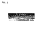
- FIG. 2 is an SIM photomicrograph showing a section of tin-plated copper-alloy material for terminal of Example 3 with magnified by 2 times in a vertical direction.
- FIG. 3 is an SIM photomicrograph showing a surface-state of a Sn-based surface layer of copper-alloy material for terminal of Comparative Example 4.
- FIG. 4 is an SIM photomicrograph showing a section of copper-alloy material for terminal of Comparative Example 4 with magnified by 2 times in a vertical direction.
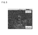
- FIG. 5 is an STEM image showing a section of tin-plated copper-alloy material for terminal of Example 2.
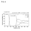
- FIG. 6 is an analytical graph by EDS along the white line in FIG. 5 .
- FIG. 7 is an STEM image showing a section of copper-alloy material for terminal of Comparative Example 4.
- FIG. 8 is an analytical graph by EDS along the white line in FIG. 7 .
- FIG. 9 is a front view schematically showing an apparatus for measuring dynamic friction coefficient.
- the tin-plated copper-alloy material for terminal of the present invention is constructed as: a Sn-based surface layer is formed on a surface of a substrate made of Cu or Cu alloy; and a CuSn alloy layer/a NiSn alloy layer/a Ni or Ni alloy layer are formed in sequence from the Sn-based surface layer between the Sn-based surface layer and the substrate.
- the substrate may be made of Cu or Cu alloy, and the composition thereof is not particularly limited.
- the Ni or Ni alloy layer is a layer which is made of pure Ni or Ni alloy such as Ni-Co, Ni-W, and the like.
- the CuSn alloy layer is a compound-alloy layer containing Cu 6 Sn 5 as a major proportion and a part of Cu in the Cu 6 Sn 5 is displaced by Ni; and the NiSn alloy layer is a compound-alloy layer containing Ni 3 Sn 4 as a major proportion and a part of Ni in the Ni 3 Sn 4 is displaced by Cu.
- Those compound layers are made by forming a Ni plating layer, a Cu plating layer, and a Sn plating layer in sequence on the substrate and then reflowing as below, so that the NiSn alloy layer and the CuSn alloy layer are made in sequence on the Ni or Ni alloy layer.
- a boundary face between the CuSn alloy layer and the Sn-based surface layer is made precipitous asperity; and an average interval S of point peaks of the CuSn alloy layer is not less than 0.8 ⁇ m and no more than 2.0 ⁇ m.
- the average interval S of the point peaks is obtained by drawing out a reference length from a roughness curve along a mean line thereof, calculating a length of the mean line corresponding to a distance between the adjacent peak points, and averaging the distances between the plurality of peak points in the reference length.
- the roughness curve can be obtained by measuring a surface of the CuSn alloy layer after removing the Sn-based surface layer by etchant.
- An average thickness of the Sn-based surface layer is not less than 0.2 ⁇ m and not more than 0.6 ⁇ m, a part of the CuSn alloy layer is exposed at a surface of the Sn-based surface layer.
- An exposed-area rate thereof is 1% or more and 40% or less; and an average of equivalent-circle diameter of exposed portions of the CuSn alloy layer is not less than 0.1 ⁇ m and not more than 1.5 ⁇ m.
- low dynamic friction coefficient of 0.3 or less can be actualized as: by existence of the (Ni, Cu) 3 Sn 4 layer in which a part of Ni is displaced by Cu under the (Cu, Ni) 6 Sn 5 alloy layer in which a part of Cu is displaced by Ni, the CuSn alloy layer has precipitous asperity in which the average interval S of the peak points is not less than 0.8 ⁇ m and not more than 2.0 ⁇ m; a depth range of several hundreds nm from the surface of the Sn-based surface layer is a composite construction of the hard CuSn alloy layer and the Sn-based surface layer; a part of the hard CuSn alloy layer is slightly exposed at the Sn-based surface layer, so that the soft Sn acts as lubricant around the exposed CuSn alloy layer.
- the exposed-area rate of the CuSn alloy layer is limited to a range of not less than 1% and not more than 40%, so that the excellent electrical-connection characteristic of the Sn-based surface layer cannot be deteriorat
- the Ni content in the Cu 6 Sn 5 alloy layer is not less than 1 at% and not more than 25 at%.
- the Ni content is set not less than 1 at%; because if it is less than 1 at%, the compound-alloy layer in which a part of Cu in Cu 6 Sn 5 is displaced by Ni cannot be made, so that the precipitous asperity cannot be made.
- the Ni content is set not more than 25 at%; because if it is more than 25 at%, the shape of the CuSn alloy layer is too fine, and there is a case in which the dynamic friction coefficient cannot be suppressed to 0.3 or less.
- the Cu content in Ni 3 Sn 4 alloy layer is preferably not less than 5 at% and not more than 20 at%.
- the condition in which the Cu content is low means that the Ni content in Cu 6 Sn 5 is also low, and the precipitous asperity cannot be made. Note that in a condition in which Cu is not displaced in Ni 3 Sn 4 , Ni is seldom displaced in Cu 6 Sn 5 .
- the upper limit is set because if Cu actually exceeds 20%, Cu does not enter into Ni 3 Sn 4 ,
- the average thickness of the Sn-based surface layer is set not less than 0.2 ⁇ m and not more than 0.6 ⁇ m: because if it is less than 0.2 ⁇ m, the soldering wettability and the electrical-connection reliability are liable to be deteriorated; or if it is more than 0.6 ⁇ m, the surface layer is not made as a composite construction of Sn and CuSn alloy, so that the dynamic friction coefficient is increased since it is filled only by Sn. More preferably, the average thickness of the Sn-based surface layer is 0.3 ⁇ m to 0.5 ⁇ m.
- the exposed-area rate of the CuSn alloy layer at the surface of the Sn-based surface layer is less than 1%, the dynamic friction coefficient cannot be suppressed to 0.3 or less; or if it is more than 40%, the electrical-connection characteristic such as the soldering wettability or the like is deteriorated. More preferably, the exposed-area rate is 2% to 20%.
- the equivalent-circle diameter is 0.2 ⁇ m to 1.0 ⁇ m.
- a plate made of Cu or Cu alloy such as Cu-Ni-Si based alloy is prepared for a substrate. Surfaces of the plate are cleaned by treatments of degreasing, pickling and the like, then Ni plating, Cu plating and Sn plating is operated in sequence.
- Ni-plating bath In Ni plating, an ordinary Ni-plating bath can be used; for example, a sulfate bath containing sulfuric acid (H 2 SO 4 ) and nickel sulfate (NiSO 4 ) as a major ingredients. Temperature of the plating bath is set to not lower than 20°C and not higher than 50°C; and current density is set to 1 to 30 A/dm 2 . A film thickness of the Ni plating layer is set not less than 0.05 ⁇ m to 1.0 ⁇ m or less.
- an ordinary Cu-plating bath can be used; for example, a copper-sulfate plating bath or the like containing copper sulfate (CuSO 4 ) and sulfuric acid (H 2 SO 4 ) as major ingredients. Temperature of the plating bath is set to 20 to 50°C; and current density is set to 1 to 30 A/dm 2 . A film thickness of the Cu plating layer made by the Cu plating is set to 0.05 ⁇ m or more and 0.20 ⁇ m or less.
- the Ni content contained in (Cu, Ni) 6 Sn 5 alloy is increased, so that the shape of the CuSn alloy is too fine; or if it is more than 0.20 ⁇ m, the Ni content contained in the (Cu, Ni) 6 Sn 5 alloy is reduced, so that the CuSn alloy having the precipitous asperity cannot be made.
- an ordinary Sn-plating bath can be used; for example, a sulfate bath containing sulfuric acid (H 2 SO 4 ) and stannous sulphate (SnSO 4 ) as major ingredients. Temperature of the plating bath is set to 15 to 35°C; and current density is set to 1 to 30 A/dm 2 . A film thickness of the Sn plating layer is set to 0.5 ⁇ m or more and 1.0 ⁇ m or less.
- the thickness of the Sn plating layer is less than 0.5 ⁇ m, the Sn-based surface layer is thin after reflowing, so that the electrical-connection characteristic is deteriorated; or if it is more than 1.0 ⁇ m, the exposure of the CuSn alloy layer at the surface is reduced, so that it is difficult to suppress the dynamic friction coefficient to 0.3 or less.
- the substrate is heated in a state in which a surface temperature of the substrate is not lower than 240°C and not higher than 360°C for not less than 1 second and not more than 12 seconds in a reduction atmosphere, and then the substrate is rapidly cooled. More preferably, the substrate is heated in a state in which the surface temperature is 260°C to 300°C for 5 seconds to 10 seconds, and then rapidly cooled.
- a hold time is adequate in a range of 1 second to 12 seconds in accordance with the thickness of the Cu plating layer and the thickness of the Sn plating layer as below; so that the hold time is short when the plating thickness is thin, and the long hold time is necessary when the plating thickness is thick.
- the thickness of the Sn plating layer is not less than 0.5 ⁇ m and less than 0.7 ⁇ m: if the thickness of the Cu plating layer is not less than 0.05 ⁇ m and less than 0.16 ⁇ m, 1 second or more and 6 seconds or less; if the thickness of the Cu plating layer is not less than 0.16 ⁇ m and not more than 0.20 ⁇ m, 3 seconds or more and 9 seconds or less
- the thickness of the Sn plating layer is not less than 0.7 ⁇ m and not more than 1.0 ⁇ m: if the thickness of the Cu plating layer is not less than 0.05 ⁇ m and less than 0.16 ⁇ m, 3 seconds or more and 9 seconds or less; if the thickness of the Cu plating layer is not less than 0.16 ⁇ m and not more than 0.20 ⁇ m, 6 seconds or more and 12 seconds or less
- Corson copper alloy (Cu-Ni-Si alloy) having a plate thickness of 0.25 mm was prepared as the substrate, and Ni-plating, Gu-plating and Sn-plating were performed in sequence on the substrate.
- plating conditions of the Ni-plating, the Cu-plating and the Sn-plating were the same in Examples and Comparative Examples as shown in Table 1.
- Dk denotes current density of a cathode
- ASD denotes abbreviation of A/dm 2 .
- the surface temperature of the substrates were risen to 240 to 360°C in reduction atmosphere as reflow treatments; subsequently, the substrates were heated for the time shown in the aforementioned (1) and (2) in accordance with the plating thickness, and then water-cooled.
- the hold time shown in (1) and (2) are tabled as Table 2.
- Table 2 Cu PLATING THICKNESS ( ⁇ m) Sn PLATING THICKNESS ( ⁇ m) 0.05 or more and less than 0.16 0.16 or more and 0.20 or less 0.5 or more and less than 0.7 1 or more and 6 or less 3 or more and 9 or less 0.7 or more and 1.0 or less 3 or more and 9 or less 6 or more and 12 or less
- the thickness of the Sn-based surface layer after reflowing the Ni content in (Cu, Ni) 6 Sn 5 alloy, presence or absence of the (Ni, Cu) 3 Sn 4 alloy layer, the exposed-area rate of the CuSn alloy layer on a Sn-based surface layer, and the equivalent-circle diameter of the exposed portions were detected; and the dynamic friction coefficient, the soldering wettability, glossiness, and the electrical-connection reliability were evaluated.
- the thicknesses of the Sn-based surface layer after reflowing were measured by an X-ray fluorescent analysis thickness meter (SFT9400) by SII Nanotechnology Inc. At first, all the thickness of the Sn-based surface layers of the samples after reflowing were measured, and then the Sn-based surface layers were removed by soaking for a few minutes in etchant for abrasion of the plate coatings made from components which do not corrode CuSn alloy but etch pure Sn, for example, by L80 or the like by Laybold Co., Ltd. so that the bottom CuSn alloy layers were exposed. Then, the thicknesses of the CuSn alloy layers in pure Sn conversion were measured. Finally, (the thicknesses of all the Sn-based surface layers minus the thickness of the CuSn alloy layer in pure Sn conversion) was defined as the thickness of the Sn-based surface layer.
- SFT9400 X-ray fluorescent analysis thickness meter
- the Ni content in the (Cu, Ni) 6 Sn 5 alloy layer and the presence or absence of the (Ni, Cu) 3 Sn 4 alloy layer were detected from sectional STEM images and by EDS linear analysis.
- the exposed-area rate and the equivalent-circle diameter of the CuSn alloy layer were observed at an area of 100 ⁇ 100 ⁇ m by a scanning ion microscope after removing surface-oxide films.
- a measurement principle if Cu 6 Sn 5 exists in a depth area of substantially 20 nm from an outermost surface, it is imaged by white; so that an area-rate of the white portions with respect to a whole area of measuring portion was regarded as the exposed-area rate of the CuSn alloy using an image processing software, the equivalent-circle diameter was calculated from the white portions, and an average value of them was regarded as the equivalent-circle diameter of CuSn alloy.
- the average interval S between the point peaks of the CuSn alloy layer was obtained by: removing the Sn-based surface layer by soaking in the etchant for abrasion of the Sn-plate coating so that the bottom CuSn alloy layer was exposed; and then obtaining from an average of measured value measured at 10 points including 5 points along a longitudinal direction and 5 points along a short direction in a condition of an object lens of 150 magnifications (a measuring field of 94 ⁇ m ⁇ 70 ⁇ m) using a laser microscope (VK-9700) made by Keyence Corporation.
- the dynamic friction coefficient was obtained by: preparing plate-shaped male test pieces and half-spherical female test pieces having an inner diameter of 1.5 mm of the samples so as to simulate a contact of a male terminal and a female terminal in an insertion-type connector; and measuring a friction force between the test pieces using a friction-measuring instrument ( ⁇ V1000) made by Trinity Lab INC. It is explained with reference to FIG. 9 that: the male test piece 12 was fixed on a horizontal table 11, a spherical convex of the female test piece 13 was deposited on the male test piece 12 so that plated surfaces were in contact with each other, and the male test piece 12 was pressed at a load P of 100 to 500 gf by the female test piece 13 with a weight 14.
- a friction force F was measured by a load cell 15 when the male test piece 12 was drawn in the horizontal direction shown by an arrow for 10 mm at a frictional speed of 80 mm/minute.
- the test pieces were cut out to have width of 10 mm; so that zero-cross time was measured by a meniscograph method using a rosin-based active flux. (The test pieces were soaked in Sn-37%Pb solder with solder-bath temperature of 230°C; so that the soldering wettability was measured in a condition in which a soaking speed was 2 mm/sec, a soaking depth was 2 mm, and a soaking time was 10 seconds.) If the soldering zero-cross time was 3 seconds or less, it was evaluated as "O"; or it was more than 3 seconds, it was evaluated as "X".
- the glossiness was measured using a gloss meter (model number: PG-1M) made by Nippon Denshoku Industries Co., Ltd. with an entry angle of 60° in accordance with JIS Z 8741.
- the contact resistance was measured with heating in the atmosphere at 150°C ⁇ 500 hours.
- the measuring method was in accordance with JIS-C-5402, load variation from 0 to 50 g - contact resistance in sliding type (1 mm) was measured using a four-terminal contact-resistance test equipment (made by Yamasaki-Seiki Co., Ltd. : CRS-113-AU), so that a contact resistance value was evaluated when the load was 50 g.
- FIG. 1 and FIG. 2 are photomicrographs of the sample of Example 3;
- FIG. 3 and FIG. 4 are photomicrographs of Comparative Example 4;
- FIG. 5 and FIG. 6 are an STEM image of a section and an EDS linear analytical result of Example 2;
- FIGS. 7 and 8 are an STEM image of a section and an EDS linear analytical result of Comparative Example 4.
- the substrate is denoted by (i)
- the Ni layer is denoted by (ii)
- the (Ni, Cu) 3 Sn 4 alloy layer is denoted by (iii)
- the (Cu, Ni) 6 Sn 5 alloy layer is denoted by (iv).
- the Ni layer is denoted by (i')
- the Cu 3 Sn alloy layer is denoted by (ii')
- the Cu 6 Sn 5 alloy layer is denoted by (iii').
- the asperity of the CuSn alloy layer was precipitous, the part of the CuSn alloy layer was dispersed and exposed at the Sn-based surface layer, and the particle diameter was small.
- Ni was contained in Cu 6 Sn 5 ; and the Ni 3 Sn 4 layer containing Cu at the boundary face between the Ni layer and the Cu 6 Sn 5 layer was made.
- the Cu contents in the Ni 3 Sn 4 layer in the material for terminal of Examples were supposed in a range of 5 to 20 at%. For example, it was 11 at% in Example 2.
Applications Claiming Priority (1)
| Application Number | Priority Date | Filing Date | Title |
|---|---|---|---|
| JP2012148575 | 2012-07-02 |
Publications (2)
| Publication Number | Publication Date |
|---|---|
| EP2682263A2 true EP2682263A2 (fr) | 2014-01-08 |
| EP2682263A3 EP2682263A3 (fr) | 2016-10-26 |
Family
ID=48700417
Family Applications (1)
| Application Number | Title | Priority Date | Filing Date |
|---|---|---|---|
| EP13174449.2A Withdrawn EP2682263A3 (fr) | 2012-07-02 | 2013-07-01 | Matériau en alliage de cuivre étamé pour terminal et son procédé de production |
Country Status (5)
| Country | Link |
|---|---|
| US (1) | US20140004373A1 (fr) |
| EP (1) | EP2682263A3 (fr) |
| KR (1) | KR20140004021A (fr) |
| CN (1) | CN103531933B (fr) |
| TW (1) | TW201413068A (fr) |
Cited By (3)
| Publication number | Priority date | Publication date | Assignee | Title |
|---|---|---|---|---|
| EP2843086A3 (fr) * | 2013-08-26 | 2015-06-03 | Mitsubishi Materials Corporation | Matériau en alliage de cuivre étamé pour terminal ayant d'excellentes performances d'insertion/extraction |
| EP2896724A1 (fr) * | 2013-12-27 | 2015-07-22 | Mitsubishi Materials Corporation | Matériau de borne en alliage de cuivre étamé |
| EP3162920B1 (fr) * | 2014-06-25 | 2020-01-22 | Nippon Steel Nisshin Co., Ltd. | Tôle d'acier inoxydable plaquée à l'étain |
Families Citing this family (11)
| Publication number | Priority date | Publication date | Assignee | Title |
|---|---|---|---|---|
| TW201311944A (zh) * | 2011-08-12 | 2013-03-16 | Mitsubishi Materials Corp | 插拔性優異的鍍錫銅合金端子材及其製造方法 |
| EP2620275B1 (fr) * | 2012-01-26 | 2019-10-02 | Mitsubishi Materials Corporation | Matériau en alliage de cuivre étamé pour terminal et son procédé de production |
| JP6445895B2 (ja) * | 2014-03-04 | 2018-12-26 | Dowaメタルテック株式会社 | Snめっき材およびその製造方法 |
| JP6160582B2 (ja) | 2014-09-11 | 2017-07-12 | 三菱マテリアル株式会社 | 錫めっき銅合金端子材及びその製造方法 |
| JP6365182B2 (ja) * | 2014-09-26 | 2018-08-01 | 株式会社オートネットワーク技術研究所 | コネクタ用電気接点材料及びその製造方法 |
| JP6543141B2 (ja) * | 2015-09-01 | 2019-07-10 | Dowaメタルテック株式会社 | Snめっき材およびその製造方法 |
| JP5939345B1 (ja) * | 2015-11-06 | 2016-06-22 | 株式会社オートネットワーク技術研究所 | 端子金具およびコネクタ |
| JP6226037B2 (ja) * | 2015-12-15 | 2017-11-08 | 三菱マテリアル株式会社 | 錫めっき付き銅端子材の製造方法 |
| JP6645337B2 (ja) * | 2016-04-20 | 2020-02-14 | 株式会社オートネットワーク技術研究所 | 接続端子および接続端子対 |
| JP6423025B2 (ja) * | 2017-01-17 | 2018-11-14 | 三菱伸銅株式会社 | 挿抜性に優れた錫めっき付銅端子材及びその製造方法 |
| JP7040224B2 (ja) | 2018-03-30 | 2022-03-23 | 三菱マテリアル株式会社 | 錫めっき付銅端子材及びその製造方法 |
Citations (3)
| Publication number | Priority date | Publication date | Assignee | Title |
|---|---|---|---|---|
| JP2005350774A (ja) | 2005-06-13 | 2005-12-22 | Dowa Mining Co Ltd | 皮膜、その製造方法および電気電子部品 |
| JP2007063624A (ja) | 2005-08-31 | 2007-03-15 | Nikko Kinzoku Kk | 挿抜性及び耐熱性に優れる銅合金すずめっき条 |
| JP2007100220A (ja) | 2007-01-25 | 2007-04-19 | Kobe Steel Ltd | 接続部品用導電材料及びその製造方法 |
Family Cites Families (10)
| Publication number | Priority date | Publication date | Assignee | Title |
|---|---|---|---|---|
| TW575688B (en) * | 2001-01-19 | 2004-02-11 | Furukawa Electric Co Ltd | Metal-plated material and method for preparation thereof, and electric and electronic parts using the same |
| US20050037229A1 (en) * | 2001-01-19 | 2005-02-17 | Hitoshi Tanaka | Plated material, method of producing same, and electrical / electronic part using same |
| US6759142B2 (en) * | 2001-07-31 | 2004-07-06 | Kobe Steel Ltd. | Plated copper alloy material and process for production thereof |
| DE10146274A1 (de) * | 2001-09-19 | 2003-04-10 | Bosch Gmbh Robert | Metallische Oberfläche eines Körpers, Verfahren zur Herstellung einer strukturierten metallischen Oberfläche eines Körpers und dessen Verwendung |
| JP3926355B2 (ja) * | 2004-09-10 | 2007-06-06 | 株式会社神戸製鋼所 | 接続部品用導電材料及びその製造方法 |
| WO2006028189A1 (fr) * | 2004-09-10 | 2006-03-16 | Kabushiki Kaisha Kobe Seiko Sho | Matériau conducteur pour pièce de connexion et procédé de fabrication du matériau conducteur |
| JP5002407B2 (ja) * | 2007-10-17 | 2012-08-15 | Jx日鉱日石金属株式会社 | すずめっきの耐磨耗性に優れるすずめっき銅又は銅合金条 |
| JP5319101B2 (ja) * | 2007-10-31 | 2013-10-16 | Jx日鉱日石金属株式会社 | 電子部品用Snめっき材 |
| JP5442316B2 (ja) * | 2009-05-12 | 2014-03-12 | 三菱伸銅株式会社 | 導電部材の製造方法 |
| JP5419594B2 (ja) * | 2009-08-24 | 2014-02-19 | 株式会社神戸製鋼所 | アルミニウム製導電部材との接続に用いられる接続部品用錫めっき付銅又は銅合金材料 |
-
2013
- 2013-06-26 TW TW102122695A patent/TW201413068A/zh unknown
- 2013-06-28 KR KR1020130075626A patent/KR20140004021A/ko not_active Application Discontinuation
- 2013-06-28 US US13/930,354 patent/US20140004373A1/en not_active Abandoned
- 2013-06-28 CN CN201310268172.2A patent/CN103531933B/zh active Active
- 2013-07-01 EP EP13174449.2A patent/EP2682263A3/fr not_active Withdrawn
Patent Citations (3)
| Publication number | Priority date | Publication date | Assignee | Title |
|---|---|---|---|---|
| JP2005350774A (ja) | 2005-06-13 | 2005-12-22 | Dowa Mining Co Ltd | 皮膜、その製造方法および電気電子部品 |
| JP2007063624A (ja) | 2005-08-31 | 2007-03-15 | Nikko Kinzoku Kk | 挿抜性及び耐熱性に優れる銅合金すずめっき条 |
| JP2007100220A (ja) | 2007-01-25 | 2007-04-19 | Kobe Steel Ltd | 接続部品用導電材料及びその製造方法 |
Cited By (3)
| Publication number | Priority date | Publication date | Assignee | Title |
|---|---|---|---|---|
| EP2843086A3 (fr) * | 2013-08-26 | 2015-06-03 | Mitsubishi Materials Corporation | Matériau en alliage de cuivre étamé pour terminal ayant d'excellentes performances d'insertion/extraction |
| EP2896724A1 (fr) * | 2013-12-27 | 2015-07-22 | Mitsubishi Materials Corporation | Matériau de borne en alliage de cuivre étamé |
| EP3162920B1 (fr) * | 2014-06-25 | 2020-01-22 | Nippon Steel Nisshin Co., Ltd. | Tôle d'acier inoxydable plaquée à l'étain |
Also Published As
| Publication number | Publication date |
|---|---|
| EP2682263A3 (fr) | 2016-10-26 |
| KR20140004021A (ko) | 2014-01-10 |
| CN103531933A (zh) | 2014-01-22 |
| CN103531933B (zh) | 2018-04-27 |
| TW201413068A (zh) | 2014-04-01 |
| US20140004373A1 (en) | 2014-01-02 |
Similar Documents
| Publication | Publication Date | Title |
|---|---|---|
| EP2682263A2 (fr) | Matériau en alliage de cuivre étamé pour terminal et son procédé de production | |
| EP2620275B1 (fr) | Matériau en alliage de cuivre étamé pour terminal et son procédé de production | |
| EP2743381B1 (fr) | Élément terminal en alliage de cuivre étamé présentant de remarquables caractéristiques d'insertion et de retrait | |
| EP2896724B1 (fr) | Matériau de borne en alliage de cuivre étamé | |
| EP2784190A1 (fr) | Matériau en alliage de cuivre étamé pour terminal ayant d'excellentes performances d'insertion/extraction | |
| EP2843086A2 (fr) | Matériau en alliage de cuivre étamé pour terminal ayant d'excellentes performances d'insertion/extraction | |
| KR102355331B1 (ko) | 주석 도금 구리 합금 단자재 및 그 제조 방법 | |
| EP2216426A1 (fr) | Matériau plaqué étain pour pièces électroniques | |
| JP5522300B1 (ja) | 挿抜性に優れた錫めっき銅合金端子材及びその製造方法 | |
| WO2009123144A1 (fr) | Barre d'alliage de cuivre étamée ayant une excellente résistance à l'abrasion, d'excellentes propriétés d'insertion et une excellente résistance à la chaleur | |
| JP2009007668A (ja) | 電気電子部品用金属材料 | |
| JP5089451B2 (ja) | コネクタ用金属材料およびその製造方法 | |
| EP2273622A1 (fr) | Matériau métallique pour connecteur et procédé de production de matériau métallique pour connecteur | |
| KR20150050397A (ko) | 주석 도금 구리 합금 단자재 | |
| US20170076834A1 (en) | Electrical contact material, method of producing an electrical contact material, and terminal | |
| JP5027013B2 (ja) | コネクタ用めっき角線材料 | |
| JP5479766B2 (ja) | 接続部品用金属角線材およびその製造方法 | |
| JP7335679B2 (ja) | 導電材 |
Legal Events
| Date | Code | Title | Description |
|---|---|---|---|
| PUAI | Public reference made under article 153(3) epc to a published international application that has entered the european phase |
Free format text: ORIGINAL CODE: 0009012 |
|
| AK | Designated contracting states |
Kind code of ref document: A2 Designated state(s): AL AT BE BG CH CY CZ DE DK EE ES FI FR GB GR HR HU IE IS IT LI LT LU LV MC MK MT NL NO PL PT RO RS SE SI SK SM TR |
|
| AX | Request for extension of the european patent |
Extension state: BA ME |
|
| PUAL | Search report despatched |
Free format text: ORIGINAL CODE: 0009013 |
|
| AK | Designated contracting states |
Kind code of ref document: A3 Designated state(s): AL AT BE BG CH CY CZ DE DK EE ES FI FR GB GR HR HU IE IS IT LI LT LU LV MC MK MT NL NO PL PT RO RS SE SI SK SM TR |
|
| AX | Request for extension of the european patent |
Extension state: BA ME |
|
| RIC1 | Information provided on ipc code assigned before grant |
Ipc: C25D 3/38 20060101ALN20160922BHEP Ipc: C25D 3/30 20060101ALN20160922BHEP Ipc: H01R 13/03 20060101ALN20160922BHEP Ipc: C22C 9/06 20060101ALI20160922BHEP Ipc: C25D 5/50 20060101ALI20160922BHEP Ipc: C23C 28/02 20060101ALI20160922BHEP Ipc: B32B 15/01 20060101AFI20160922BHEP Ipc: C25D 5/12 20060101ALI20160922BHEP Ipc: C25D 3/12 20060101ALN20160922BHEP Ipc: C25D 7/00 20060101ALI20160922BHEP |
|
| STAA | Information on the status of an ep patent application or granted ep patent |
Free format text: STATUS: THE APPLICATION IS DEEMED TO BE WITHDRAWN |
|
| 18D | Application deemed to be withdrawn |
Effective date: 20170427 |