EP2682217B1 - Method for fabricating slidable member - Google Patents
Method for fabricating slidable member Download PDFInfo
- Publication number
- EP2682217B1 EP2682217B1 EP12752662.2A EP12752662A EP2682217B1 EP 2682217 B1 EP2682217 B1 EP 2682217B1 EP 12752662 A EP12752662 A EP 12752662A EP 2682217 B1 EP2682217 B1 EP 2682217B1
- Authority
- EP
- European Patent Office
- Prior art keywords
- bulk material
- based alloy
- alloy
- scm435
- shoe
- Prior art date
- Legal status (The legal status is an assumption and is not a legal conclusion. Google has not performed a legal analysis and makes no representation as to the accuracy of the status listed.)
- Active
Links
- 238000000034 method Methods 0.000 title claims description 34
- 239000013590 bulk material Substances 0.000 claims description 117
- 229910045601 alloy Inorganic materials 0.000 claims description 60
- 239000000956 alloy Substances 0.000 claims description 60
- 229910017518 Cu Zn Inorganic materials 0.000 claims description 43
- XEEYBQQBJWHFJM-UHFFFAOYSA-N Iron Chemical compound [Fe] XEEYBQQBJWHFJM-UHFFFAOYSA-N 0.000 claims description 43
- 229910017752 Cu-Zn Inorganic materials 0.000 claims description 42
- 229910017943 Cu—Zn Inorganic materials 0.000 claims description 42
- TVZPLCNGKSPOJA-UHFFFAOYSA-N copper zinc Chemical compound [Cu].[Zn] TVZPLCNGKSPOJA-UHFFFAOYSA-N 0.000 claims description 42
- 229910052742 iron Inorganic materials 0.000 claims description 21
- 238000002490 spark plasma sintering Methods 0.000 claims description 20
- 238000004519 manufacturing process Methods 0.000 claims description 15
- 238000007747 plating Methods 0.000 claims description 10
- 229910052751 metal Inorganic materials 0.000 claims description 8
- 239000002184 metal Substances 0.000 claims description 8
- 239000007790 solid phase Substances 0.000 claims description 8
- 239000011230 binding agent Substances 0.000 claims description 4
- 238000005304 joining Methods 0.000 description 26
- 239000010949 copper Substances 0.000 description 24
- 229910000881 Cu alloy Inorganic materials 0.000 description 19
- 229910052802 copper Inorganic materials 0.000 description 19
- RYGMFSIKBFXOCR-UHFFFAOYSA-N Copper Chemical compound [Cu] RYGMFSIKBFXOCR-UHFFFAOYSA-N 0.000 description 18
- 238000009792 diffusion process Methods 0.000 description 12
- 238000002149 energy-dispersive X-ray emission spectroscopy Methods 0.000 description 12
- 238000013507 mapping Methods 0.000 description 12
- 239000000463 material Substances 0.000 description 12
- 230000008569 process Effects 0.000 description 11
- 229910002482 Cu–Ni Inorganic materials 0.000 description 10
- 239000000203 mixture Substances 0.000 description 10
- PXHVJJICTQNCMI-UHFFFAOYSA-N Nickel Chemical compound [Ni] PXHVJJICTQNCMI-UHFFFAOYSA-N 0.000 description 9
- 238000012360 testing method Methods 0.000 description 8
- 239000011701 zinc Substances 0.000 description 8
- 238000010438 heat treatment Methods 0.000 description 7
- 229910000831 Steel Inorganic materials 0.000 description 6
- 230000000052 comparative effect Effects 0.000 description 6
- 239000000470 constituent Substances 0.000 description 6
- 239000000843 powder Substances 0.000 description 6
- 239000010959 steel Substances 0.000 description 6
- 229910001209 Low-carbon steel Inorganic materials 0.000 description 5
- 238000002844 melting Methods 0.000 description 5
- 230000008018 melting Effects 0.000 description 5
- 238000003825 pressing Methods 0.000 description 5
- 239000002994 raw material Substances 0.000 description 5
- 238000005245 sintering Methods 0.000 description 5
- 239000007787 solid Substances 0.000 description 5
- 230000015572 biosynthetic process Effects 0.000 description 4
- 229910052759 nickel Inorganic materials 0.000 description 4
- 239000002699 waste material Substances 0.000 description 4
- 230000007246 mechanism Effects 0.000 description 3
- 238000003746 solid phase reaction Methods 0.000 description 3
- 239000006104 solid solution Substances 0.000 description 3
- QGZKDVFQNNGYKY-UHFFFAOYSA-N Ammonia Chemical compound N QGZKDVFQNNGYKY-UHFFFAOYSA-N 0.000 description 2
- 229910001369 Brass Inorganic materials 0.000 description 2
- UGFAIRIUMAVXCW-UHFFFAOYSA-N Carbon monoxide Chemical compound [O+]#[C-] UGFAIRIUMAVXCW-UHFFFAOYSA-N 0.000 description 2
- HCHKCACWOHOZIP-UHFFFAOYSA-N Zinc Chemical compound [Zn] HCHKCACWOHOZIP-UHFFFAOYSA-N 0.000 description 2
- 239000010951 brass Substances 0.000 description 2
- 229910002091 carbon monoxide Inorganic materials 0.000 description 2
- 238000001816 cooling Methods 0.000 description 2
- 238000005520 cutting process Methods 0.000 description 2
- 238000010586 diagram Methods 0.000 description 2
- 238000007731 hot pressing Methods 0.000 description 2
- 238000005259 measurement Methods 0.000 description 2
- 238000010587 phase diagram Methods 0.000 description 2
- 230000009467 reduction Effects 0.000 description 2
- 229910052725 zinc Inorganic materials 0.000 description 2
- 229910000906 Bronze Inorganic materials 0.000 description 1
- 229910002535 CuZn Inorganic materials 0.000 description 1
- CWYNVVGOOAEACU-UHFFFAOYSA-N Fe2+ Chemical compound [Fe+2] CWYNVVGOOAEACU-UHFFFAOYSA-N 0.000 description 1
- 229910002056 binary alloy Inorganic materials 0.000 description 1
- 238000005255 carburizing Methods 0.000 description 1
- 238000006243 chemical reaction Methods 0.000 description 1
- 238000010276 construction Methods 0.000 description 1
- 230000007423 decrease Effects 0.000 description 1
- 230000000694 effects Effects 0.000 description 1
- 230000005684 electric field Effects 0.000 description 1
- 230000005496 eutectics Effects 0.000 description 1
- 230000001747 exhibiting effect Effects 0.000 description 1
- 239000012530 fluid Substances 0.000 description 1
- 238000011835 investigation Methods 0.000 description 1
- 239000000314 lubricant Substances 0.000 description 1
- 238000012986 modification Methods 0.000 description 1
- 230000004048 modification Effects 0.000 description 1
- 229910000069 nitrogen hydride Inorganic materials 0.000 description 1
- 230000000149 penetrating effect Effects 0.000 description 1
- 230000002093 peripheral effect Effects 0.000 description 1
- 239000012071 phase Substances 0.000 description 1
- 239000000243 solution Substances 0.000 description 1
- 239000000126 substance Substances 0.000 description 1
Images


Classifications
-
- B—PERFORMING OPERATIONS; TRANSPORTING
- B22—CASTING; POWDER METALLURGY
- B22F—WORKING METALLIC POWDER; MANUFACTURE OF ARTICLES FROM METALLIC POWDER; MAKING METALLIC POWDER; APPARATUS OR DEVICES SPECIALLY ADAPTED FOR METALLIC POWDER
- B22F3/00—Manufacture of workpieces or articles from metallic powder characterised by the manner of compacting or sintering; Apparatus specially adapted therefor ; Presses and furnaces
- B22F3/10—Sintering only
- B22F3/105—Sintering only by using electric current other than for infrared radiant energy, laser radiation or plasma ; by ultrasonic bonding
-
- B—PERFORMING OPERATIONS; TRANSPORTING
- B22—CASTING; POWDER METALLURGY
- B22F—WORKING METALLIC POWDER; MANUFACTURE OF ARTICLES FROM METALLIC POWDER; MAKING METALLIC POWDER; APPARATUS OR DEVICES SPECIALLY ADAPTED FOR METALLIC POWDER
- B22F3/00—Manufacture of workpieces or articles from metallic powder characterised by the manner of compacting or sintering; Apparatus specially adapted therefor ; Presses and furnaces
- B22F3/12—Both compacting and sintering
- B22F3/14—Both compacting and sintering simultaneously
-
- B—PERFORMING OPERATIONS; TRANSPORTING
- B22—CASTING; POWDER METALLURGY
- B22F—WORKING METALLIC POWDER; MANUFACTURE OF ARTICLES FROM METALLIC POWDER; MAKING METALLIC POWDER; APPARATUS OR DEVICES SPECIALLY ADAPTED FOR METALLIC POWDER
- B22F5/00—Manufacture of workpieces or articles from metallic powder characterised by the special shape of the product
- B22F5/008—Manufacture of workpieces or articles from metallic powder characterised by the special shape of the product of engine cylinder parts or of piston parts other than piston rings
-
- B—PERFORMING OPERATIONS; TRANSPORTING
- B22—CASTING; POWDER METALLURGY
- B22F—WORKING METALLIC POWDER; MANUFACTURE OF ARTICLES FROM METALLIC POWDER; MAKING METALLIC POWDER; APPARATUS OR DEVICES SPECIALLY ADAPTED FOR METALLIC POWDER
- B22F7/00—Manufacture of composite layers, workpieces, or articles, comprising metallic powder, by sintering the powder, with or without compacting wherein at least one part is obtained by sintering or compression
- B22F7/02—Manufacture of composite layers, workpieces, or articles, comprising metallic powder, by sintering the powder, with or without compacting wherein at least one part is obtained by sintering or compression of composite layers
-
- B—PERFORMING OPERATIONS; TRANSPORTING
- B22—CASTING; POWDER METALLURGY
- B22F—WORKING METALLIC POWDER; MANUFACTURE OF ARTICLES FROM METALLIC POWDER; MAKING METALLIC POWDER; APPARATUS OR DEVICES SPECIALLY ADAPTED FOR METALLIC POWDER
- B22F7/00—Manufacture of composite layers, workpieces, or articles, comprising metallic powder, by sintering the powder, with or without compacting wherein at least one part is obtained by sintering or compression
- B22F7/06—Manufacture of composite layers, workpieces, or articles, comprising metallic powder, by sintering the powder, with or without compacting wherein at least one part is obtained by sintering or compression of composite workpieces or articles from parts, e.g. to form tipped tools
- B22F7/08—Manufacture of composite layers, workpieces, or articles, comprising metallic powder, by sintering the powder, with or without compacting wherein at least one part is obtained by sintering or compression of composite workpieces or articles from parts, e.g. to form tipped tools with one or more parts not made from powder
-
- B—PERFORMING OPERATIONS; TRANSPORTING
- B23—MACHINE TOOLS; METAL-WORKING NOT OTHERWISE PROVIDED FOR
- B23K—SOLDERING OR UNSOLDERING; WELDING; CLADDING OR PLATING BY SOLDERING OR WELDING; CUTTING BY APPLYING HEAT LOCALLY, e.g. FLAME CUTTING; WORKING BY LASER BEAM
- B23K10/00—Welding or cutting by means of a plasma
- B23K10/02—Plasma welding
- B23K10/027—Welding for purposes other than joining, e.g. build-up welding
-
- B—PERFORMING OPERATIONS; TRANSPORTING
- B23—MACHINE TOOLS; METAL-WORKING NOT OTHERWISE PROVIDED FOR
- B23K—SOLDERING OR UNSOLDERING; WELDING; CLADDING OR PLATING BY SOLDERING OR WELDING; CUTTING BY APPLYING HEAT LOCALLY, e.g. FLAME CUTTING; WORKING BY LASER BEAM
- B23K35/00—Rods, electrodes, materials, or media, for use in soldering, welding, or cutting
- B23K35/001—Interlayers, transition pieces for metallurgical bonding of workpieces
- B23K35/007—Interlayers, transition pieces for metallurgical bonding of workpieces at least one of the workpieces being of copper or another noble metal
-
- B—PERFORMING OPERATIONS; TRANSPORTING
- B23—MACHINE TOOLS; METAL-WORKING NOT OTHERWISE PROVIDED FOR
- B23P—METAL-WORKING NOT OTHERWISE PROVIDED FOR; COMBINED OPERATIONS; UNIVERSAL MACHINE TOOLS
- B23P15/00—Making specific metal objects by operations not covered by a single other subclass or a group in this subclass
-
- B—PERFORMING OPERATIONS; TRANSPORTING
- B32—LAYERED PRODUCTS
- B32B—LAYERED PRODUCTS, i.e. PRODUCTS BUILT-UP OF STRATA OF FLAT OR NON-FLAT, e.g. CELLULAR OR HONEYCOMB, FORM
- B32B15/00—Layered products comprising a layer of metal
- B32B15/01—Layered products comprising a layer of metal all layers being exclusively metallic
- B32B15/013—Layered products comprising a layer of metal all layers being exclusively metallic one layer being formed of an iron alloy or steel, another layer being formed of a metal other than iron or aluminium
- B32B15/015—Layered products comprising a layer of metal all layers being exclusively metallic one layer being formed of an iron alloy or steel, another layer being formed of a metal other than iron or aluminium the said other metal being copper or nickel or an alloy thereof
-
- C—CHEMISTRY; METALLURGY
- C22—METALLURGY; FERROUS OR NON-FERROUS ALLOYS; TREATMENT OF ALLOYS OR NON-FERROUS METALS
- C22C—ALLOYS
- C22C1/00—Making non-ferrous alloys
- C22C1/02—Making non-ferrous alloys by melting
-
- C—CHEMISTRY; METALLURGY
- C22—METALLURGY; FERROUS OR NON-FERROUS ALLOYS; TREATMENT OF ALLOYS OR NON-FERROUS METALS
- C22C—ALLOYS
- C22C1/00—Making non-ferrous alloys
- C22C1/04—Making non-ferrous alloys by powder metallurgy
- C22C1/0425—Copper-based alloys
-
- C—CHEMISTRY; METALLURGY
- C22—METALLURGY; FERROUS OR NON-FERROUS ALLOYS; TREATMENT OF ALLOYS OR NON-FERROUS METALS
- C22C—ALLOYS
- C22C38/00—Ferrous alloys, e.g. steel alloys
- C22C38/02—Ferrous alloys, e.g. steel alloys containing silicon
-
- C—CHEMISTRY; METALLURGY
- C22—METALLURGY; FERROUS OR NON-FERROUS ALLOYS; TREATMENT OF ALLOYS OR NON-FERROUS METALS
- C22C—ALLOYS
- C22C38/00—Ferrous alloys, e.g. steel alloys
- C22C38/04—Ferrous alloys, e.g. steel alloys containing manganese
-
- C—CHEMISTRY; METALLURGY
- C22—METALLURGY; FERROUS OR NON-FERROUS ALLOYS; TREATMENT OF ALLOYS OR NON-FERROUS METALS
- C22C—ALLOYS
- C22C38/00—Ferrous alloys, e.g. steel alloys
- C22C38/18—Ferrous alloys, e.g. steel alloys containing chromium
-
- C—CHEMISTRY; METALLURGY
- C22—METALLURGY; FERROUS OR NON-FERROUS ALLOYS; TREATMENT OF ALLOYS OR NON-FERROUS METALS
- C22C—ALLOYS
- C22C38/00—Ferrous alloys, e.g. steel alloys
- C22C38/18—Ferrous alloys, e.g. steel alloys containing chromium
- C22C38/22—Ferrous alloys, e.g. steel alloys containing chromium with molybdenum or tungsten
-
- C—CHEMISTRY; METALLURGY
- C22—METALLURGY; FERROUS OR NON-FERROUS ALLOYS; TREATMENT OF ALLOYS OR NON-FERROUS METALS
- C22C—ALLOYS
- C22C38/00—Ferrous alloys, e.g. steel alloys
- C22C38/18—Ferrous alloys, e.g. steel alloys containing chromium
- C22C38/40—Ferrous alloys, e.g. steel alloys containing chromium with nickel
-
- C—CHEMISTRY; METALLURGY
- C22—METALLURGY; FERROUS OR NON-FERROUS ALLOYS; TREATMENT OF ALLOYS OR NON-FERROUS METALS
- C22C—ALLOYS
- C22C9/00—Alloys based on copper
- C22C9/01—Alloys based on copper with aluminium as the next major constituent
-
- C—CHEMISTRY; METALLURGY
- C22—METALLURGY; FERROUS OR NON-FERROUS ALLOYS; TREATMENT OF ALLOYS OR NON-FERROUS METALS
- C22C—ALLOYS
- C22C9/00—Alloys based on copper
- C22C9/02—Alloys based on copper with tin as the next major constituent
-
- C—CHEMISTRY; METALLURGY
- C22—METALLURGY; FERROUS OR NON-FERROUS ALLOYS; TREATMENT OF ALLOYS OR NON-FERROUS METALS
- C22C—ALLOYS
- C22C9/00—Alloys based on copper
- C22C9/04—Alloys based on copper with zinc as the next major constituent
-
- C—CHEMISTRY; METALLURGY
- C22—METALLURGY; FERROUS OR NON-FERROUS ALLOYS; TREATMENT OF ALLOYS OR NON-FERROUS METALS
- C22C—ALLOYS
- C22C9/00—Alloys based on copper
- C22C9/06—Alloys based on copper with nickel or cobalt as the next major constituent
-
- C—CHEMISTRY; METALLURGY
- C22—METALLURGY; FERROUS OR NON-FERROUS ALLOYS; TREATMENT OF ALLOYS OR NON-FERROUS METALS
- C22C—ALLOYS
- C22C9/00—Alloys based on copper
- C22C9/08—Alloys based on copper with lead as the next major constituent
-
- F—MECHANICAL ENGINEERING; LIGHTING; HEATING; WEAPONS; BLASTING
- F04—POSITIVE - DISPLACEMENT MACHINES FOR LIQUIDS; PUMPS FOR LIQUIDS OR ELASTIC FLUIDS
- F04B—POSITIVE-DISPLACEMENT MACHINES FOR LIQUIDS; PUMPS
- F04B1/00—Multi-cylinder machines or pumps characterised by number or arrangement of cylinders
- F04B1/04—Multi-cylinder machines or pumps characterised by number or arrangement of cylinders having cylinders in star- or fan-arrangement
- F04B1/0404—Details or component parts
- F04B1/0408—Pistons
-
- F—MECHANICAL ENGINEERING; LIGHTING; HEATING; WEAPONS; BLASTING
- F04—POSITIVE - DISPLACEMENT MACHINES FOR LIQUIDS; PUMPS FOR LIQUIDS OR ELASTIC FLUIDS
- F04B—POSITIVE-DISPLACEMENT MACHINES FOR LIQUIDS; PUMPS
- F04B1/00—Multi-cylinder machines or pumps characterised by number or arrangement of cylinders
- F04B1/12—Multi-cylinder machines or pumps characterised by number or arrangement of cylinders having cylinder axes coaxial with, or parallel or inclined to, main shaft axis
- F04B1/122—Details or component parts, e.g. valves, sealings or lubrication means
- F04B1/124—Pistons
-
- F—MECHANICAL ENGINEERING; LIGHTING; HEATING; WEAPONS; BLASTING
- F04—POSITIVE - DISPLACEMENT MACHINES FOR LIQUIDS; PUMPS FOR LIQUIDS OR ELASTIC FLUIDS
- F04B—POSITIVE-DISPLACEMENT MACHINES FOR LIQUIDS; PUMPS
- F04B1/00—Multi-cylinder machines or pumps characterised by number or arrangement of cylinders
- F04B1/12—Multi-cylinder machines or pumps characterised by number or arrangement of cylinders having cylinder axes coaxial with, or parallel or inclined to, main shaft axis
- F04B1/20—Multi-cylinder machines or pumps characterised by number or arrangement of cylinders having cylinder axes coaxial with, or parallel or inclined to, main shaft axis having rotary cylinder block
- F04B1/2014—Details or component parts
- F04B1/2078—Swash plates
-
- F—MECHANICAL ENGINEERING; LIGHTING; HEATING; WEAPONS; BLASTING
- F04—POSITIVE - DISPLACEMENT MACHINES FOR LIQUIDS; PUMPS FOR LIQUIDS OR ELASTIC FLUIDS
- F04B—POSITIVE-DISPLACEMENT MACHINES FOR LIQUIDS; PUMPS
- F04B53/00—Component parts, details or accessories not provided for in, or of interest apart from, groups F04B1/00 - F04B23/00 or F04B39/00 - F04B47/00
- F04B53/14—Pistons, piston-rods or piston-rod connections
-
- B—PERFORMING OPERATIONS; TRANSPORTING
- B23—MACHINE TOOLS; METAL-WORKING NOT OTHERWISE PROVIDED FOR
- B23K—SOLDERING OR UNSOLDERING; WELDING; CLADDING OR PLATING BY SOLDERING OR WELDING; CUTTING BY APPLYING HEAT LOCALLY, e.g. FLAME CUTTING; WORKING BY LASER BEAM
- B23K2103/00—Materials to be soldered, welded or cut
- B23K2103/18—Dissimilar materials
- B23K2103/22—Ferrous alloys and copper or alloys thereof
-
- F—MECHANICAL ENGINEERING; LIGHTING; HEATING; WEAPONS; BLASTING
- F05—INDEXING SCHEMES RELATING TO ENGINES OR PUMPS IN VARIOUS SUBCLASSES OF CLASSES F01-F04
- F05C—INDEXING SCHEME RELATING TO MATERIALS, MATERIAL PROPERTIES OR MATERIAL CHARACTERISTICS FOR MACHINES, ENGINES OR PUMPS OTHER THAN NON-POSITIVE-DISPLACEMENT MACHINES OR ENGINES
- F05C2201/00—Metals
- F05C2201/04—Heavy metals
- F05C2201/0469—Other heavy metals
- F05C2201/0475—Copper or alloys thereof
-
- Y—GENERAL TAGGING OF NEW TECHNOLOGICAL DEVELOPMENTS; GENERAL TAGGING OF CROSS-SECTIONAL TECHNOLOGIES SPANNING OVER SEVERAL SECTIONS OF THE IPC; TECHNICAL SUBJECTS COVERED BY FORMER USPC CROSS-REFERENCE ART COLLECTIONS [XRACs] AND DIGESTS
- Y10—TECHNICAL SUBJECTS COVERED BY FORMER USPC
- Y10T—TECHNICAL SUBJECTS COVERED BY FORMER US CLASSIFICATION
- Y10T29/00—Metal working
- Y10T29/49—Method of mechanical manufacture
Definitions
- the present invention relates to a method of manufacturing a sliding member having a sliding portion according to the preamble of claim 1 (see, for example, EP1 508 693 A2 ).
- a sliding member that uses a copper alloy for a sliding portion in order to improve a sliding ability of the sliding portion is known in the related art.
- JP2005-257035A discloses plating a copper base layer onto a surface of a steel member and sintering a lead-bronze alloy powder to the steel member via the plating.
- a solid solubility of copper in iron is 1.9at% and the solid solubility of iron in copper is 4.6at%, and therefore iron and copper substantially do not enter into a mutual solid solution.
- plating is typically used as a binder to join the steel member and the copper alloy securely.
- Prior art document EP 1 508 693 A2 discloses a sliding member made by sintering a mixture of a bronze powder and a Cu-plated solid lubricant onto a backing plate.
- Document JP 2007 253240 A relates to joining metal parts like pipes or tubes via a sintering process.
- Document JP H11 58034 A relates to a method for plating a ferrous material with a brass alloy.
- the present invention has been designed in consideration of this problem, and an object thereof is to join an iron based metal to a Cu alloy serving as a sliding portion easily and with a high degree of joint strength.
- a method of manufacturing a sliding member having a sliding portion is defined in claim 1.
- the piston pump 100 is installed in a construction machine such as a hydraulic shovel or a hydraulic crane, for example, in order to supply a working fluid (working oil) to a hydraulic cylinder or a hydraulic motor serving as an actuator.
- a working fluid working oil
- the piston pump 100 includes a drive shaft 1 to which power from an engine is transmitted, and a cylinder block 2 that rotates as the drive shaft 1 rotates.
- a plurality of cylinder bores 3 are opened in the cylinder block 2 to be parallel to the drive shaft 1.
- a piston 5 that defines a volume chamber 4 is inserted into each cylinder bore 3 to be free to reciprocate.
- a shoe 10 is coupled to a tip end of the piston 5 via a spherically-shaped spherical washer 11 to be free to rotate.
- the shoe 10 includes a flat plate portion 12 formed integrally with the spherical washer 11.
- the flat plate portion 12 is in surface contact with a swash plate 20 fixed to a case 21.
- the flat plate portion 12 of each shoe 10 slides along the swash plate 20 such that each piston 5 reciprocates by a stroke corresponding to a tilt angle of the swash plate 20.
- a volume of each volume chamber 4 is increased and reduced by the reciprocation of the piston 5.
- a valve plate 23 along which a base end surface of the cylinder block 2 slides is attached to a case 22.
- An intake port and a discharge port, not shown in the figure, are formed in the valve plate 23.
- the working oil is led into the volume chamber 4 through the intake port as the cylinder block 2 rotates, and the working oil led into the volume chamber 4 is discharged through the discharge port.
- the piston 5 reciprocate together with the rotation of the cylinder block 2 in this manner, the working oil is continuously taken into and discharged from the piston pump 100.
- a sliding portion 14 made of a Cu alloy having a superior sliding ability is provided on a surface of the flat plate portion 12 that slides along the swash plate 20.
- the shoe 10 is constituted by a main body portion 13 including the spherical washer 11 and the flat plate portion 12, and the sliding portion 14 that slides along the swash plate 20.
- a bulk material 30 that is made of an iron based metal and functions as the main body portion 13, and a bulk material 31 that is made of a Cu alloy and functions as the sliding portion 14 are used to manufacture the shoe 10.
- the bulk material 30 and the bulk material 31 are columnar members having an identical diameter to a diameter of the shoe 10.
- SCM435 (JIS) made of Cr-Mo steel is used as the iron based metal of the bulk material 30.
- a Cu-Zn based alloy is used as the Cu alloy of the bulk material 31.
- a Cu alloy is an alloy having copper as a main component.
- a Cu-Zn based alloy, as used in the method in the present invention, is an alloy having copper as a main component and containing zinc.
- the zinc preferably occupies no more than 35wt% of the alloy.
- Table 1 shows respective compositions of the bulk material 30 (SCM435) and the bulk material 31 (Cu-Zn based alloy).
- compositions of bulk material 30 SCM435) and bulk material 31 (Cu-Zn based alloy) (wt%) Table 1 C Si Mn P S Ni Cr Cu Zn Fe Al Mo SCM435 033 ⁇ 0.38 0.15 ⁇ 0.35 0.60 ⁇ 0.90 ⁇ 0.030 ⁇ 0.030 ⁇ 0.25 0.90 ⁇ 1.20 96.7 ⁇ 97.6 0.15 ⁇ 0.30 Cu-Zn based alloy 0.5 ⁇ 1.5 2.0 ⁇ 4.0 58.7 ⁇ 68 26 ⁇ 30 0.5 ⁇ 1.3 3.0 ⁇ 4.5
- the bulk material 30 is cut to a desired thickness. More specifically, the bulk material 30 is cut to a dimension corresponding to an axial direction length of the main body portion 13.
- the bulk material 31 is also cut to a desired thickness. More specifically, the bulk material 31 is cut to a dimension corresponding to a thickness of the sliding portion 14.
- spark plasma sintering is a sintering method in which diffusion of heat and an electric field is assisted by spark plasma that is generated momentarily when a pulse-form large current is applied to a gap between joining subject bodies at a low voltage.
- the spark plasma sintering device 40 includes a cylindrical jig 48 made of high-strength WC, in which a joining subject member is housed, an upper punch 41a and a lower punch 41b that sandwich the joining subject member so that the joining subject member is held in the jig 48, an upper electrode 42a and a lower electrode 42b that are disposed in contact with the upper punch 41a and the lower punch 41 b, respectively, in order to apply a current to the joining subject member, a power supply 43 connected to the upper electrode 42a and the lower electrode 42b, a pressure application mechanism 44 that presses the upper punch 41a and the lower punch 41b via the upper electrode 42a and the lower electrode 42b in order to apply a pressing force to the joining subject member, and a control device 45 that controls the power supply 43 and the pressure application mechanism 44.
- the jig 48 is disposed in a vacuum chamber 46 so that the joining subject member is joined in a vacuum atmosphere.
- a through hole is formed in a trunk portion of the jig 48 to penetrate inner and outer peripheral surfaces thereof, and a thermocouple 47 is inserted into the through hole.
- the thermocouple 47 is disposed such that a tip end thereof is positioned in the vicinity of a joint surface of the joining subject member, and therefore a temperature of the joint surface of the joining subject member can be measured.
- a measurement result obtained by the thermocouple 47 is transmitted to the control device 45, and the control device 45 controls the power supply 43 on the basis of the measurement result so that the temperature and a temperature increase speed of the joint surface of the joining subject member reach predetermined set values.
- the bulk material 30 and the bulk material 31 are housed in a hollow portion of the jig 48 and sandwiched by the upper punch 41a and the lower punch 41b.
- the bulk material 30 and the bulk material 31 are housed in the jig 48 such that respective end surfaces thereof are laminated in contact with each other.
- a current is then applied to the bulk material 30 and the bulk material 31 via the power supply 43, whereby the bulk material 30 and the bulk material 31 are increased in temperature to a predetermined temperature at a predetermined temperature increase speed.
- the predetermined temperature or in other words a joining temperature
- a predetermined pressing force is applied to the bulk material 30 and the bulk material 31 by the pressure application mechanism 44 via the upper punch 41a and the lower punch 41 b, whereupon this condition is maintained for a fixed time.
- the bulk material 30 and the bulk material 31 are joined by a solid phase reaction caused by generating spark plasma on a joint interface between the bulk material 30 and the bulk material 31 while heating and pressing the bulk material 30 and the bulk material 31 in a condition where the respective end surfaces thereof are in close contact with each other.
- the bulk material 30 and the bulk material 31 undergo compressive deformation when pressure is applied thereto, leading to a thickness reduction of approximately 5%.
- the bulk material 30 and the bulk material 31 can be joined directly by a solid phase reaction caused by generating spark plasma on the joint interface between the bulk material 30 and the bulk material 31 while applying a pressing force thereto.
- a possible reason for this is that high-capacity energy generated when the spark plasma is applied can be concentrated locally, and therefore energy can be concentrated on the joint interface between the bulk material 30 and the bulk material 31, thereby assisting interdiffusion of respective atoms thereof.
- spark plasma sintering is performed on the bulk material 30 and the bulk material 31, only the respective end surfaces thereof serve as the joint interface, and therefore a joint area can be reduced greatly to approximately one five-thousandth that of a case in which powders are joined to each other by spark plasma sintering.
- spark plasma sintering is performed on the bulk material 30 and the bulk material 31, an amount of energy generated by spark plasma application per unit joint area is large, and therefore the bulk material 30 and the bulk material 31 can be joined directly.
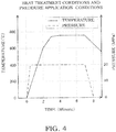
- FIG. 4 heat treatment conditions and pressure application conditions for joining the bulk material 30 and the bulk material 31 will be described.
- a solid line indicates temperature and a dotted line indicates pressure.
- the pressure application meanwhile, is started at the same time as the temperature is increased, whereupon the pressure is maintained at 20MPa and then released simultaneously with the natural cooling.
- a total of seven minutes is required for joining, and therefore joining is completed in a short time.
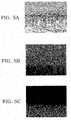
- FIGS. 5A to 5C show scanning electron microscope photographs of the joint interface between the bulk material 30 and the bulk material 31 joined under the heat treatment conditions and pressure application conditions shown in FIG. 4 .
- FIG. 5A is a secondary electron image
- FIG. 5B is a mapping image of FeL ⁇ obtained through EDX analysis
- FIG. 5C is a mapping image of CuL ⁇ obtained through EDX analysis.
- an upper side of the photographs shows the SCM435 and a lower side of the photographs shows the Cu-Zn based alloy. As is evident from FIG.
- the actually employed Cu-Zn based alloy is an alloy known as brass, which contains between 20 and 40wt% of Zn and is therefore both workable and strong, and which has been put to practical use as a structural material since ancient times.
- the melting point of Cu is 1085°C, but by increasing the amount of Zn, the melting point decreases continuously such that a peritectic composition containing 36.8wt% of Zn has a melting point of 902°C. This assists the Zn, which has a melting point of 419°C, and the Cu in forming an FCC solid solution widely up to a peritectic reaction composition, and therefore, by adding Zn, diffusion of the constituent elements of the Cu alloy is achieved more quickly.
- a solid phase joint can be realized using the spark plasma sintering method.
- Si can be expected to diffuse from the Cu-Zn based alloy to the SCM435, and therefore a concentration gradient may be formed.
- the solubility limit of Al, which is a constituent element of the Cu-Zn based alloy, into Fe is 55.0at% at a eutectic temperature of 1102°C, while the solubility limit of Al into Cu is 19.7at% at 567°C.
- Al can be expected to diffuse from the Cu-Zn based alloy to the SCM435, and therefore a concentration gradient may be formed.
- FIGS. 6A and 6B show scanning electron microscope photographs of the joint interface between the bulk material 30 and the bulk material 31.
- FIG. 6A is a mapping image of SiK ⁇ obtained through EDX analysis
- FIG. 6B is a mapping image of AlK ⁇ obtained through EDX analysis.
- the upper side of the photographs shows the SCM435 and the lower side of the photographs shows the Cu-Zn based alloy. It is evident from FIG. 6A that Si exhibits a strong concentration gradient. Further, it is evident from FIG. 6B that Al also exhibits a concentration gradient, albeit not as strongly as Si.
- the joint strength was evaluated in a peel test performed by pulling the joined bulk material 30 and bulk material 31 in opposite directions and measuring a peel strength at a point where the bulk material 30 and the bulk material 31 peeled away from each other.
- Table 2 shows results of the peel test
- Table 3 shows results of a peel test performed on a comparative material.
- the comparative material was obtained by a conventional manufacturing method in which low carbon steel and a Cu alloy were joined by sintering a Cu alloy powder onto a copper base layer plated to the low carbon steel.
- Table 4 shows compositions of the low carbon steel and the Cu alloy powder serving as the comparative material.
- the joint strength of the bulk material 30 and the bulk material 31 is greater than that of the comparative material.
- compositions of low carbon steel and Cu alloy powder Table 4 C Si Mn P S Ni Cu Pb Fe Sn Ag Impure Substance low carbon steel 0.05 ⁇ 0.25 ⁇ 0.5 ⁇ 1.0 ⁇ 0.05 ⁇ 0.05 Rest Cu alloy powder ⁇ 0.5 Rest 8.5 ⁇ 11.5 ⁇ 0.5 8.5 ⁇ 11.5 ⁇ 0.5 ⁇ 1.0
- the bulk material 30 and the bulk material 31 are joined firmly in the second process shown in FIG. 2 , whereby a raw material 32 serving as a foundation of the shoe 10 is obtained.
- the raw material 32 is fashioned into a desired shape. More specifically, a part of the raw material 32 constituted by the bulk material 30 is cut into the respective shapes of the spherical washer 11 and the flat plate portion 12. Further, a part constituted by the bulk material 31 is formed into the sliding portion 14 by cutting a circular groove 31a in an end surface thereof. Finally, a through hole (not shown) penetrating in an axial direction is cut into the spherical washer 11, the flat plate portion 12, and the sliding portion 14. This through hole is used to introduce the working oil inside the piston 5 into the groove 31a in order to reduce a surface pressure between the sliding portion 14 and the swash plate 20. Note that the groove 31a is not an essential configuration and may be omitted.
- Waste material generated when the raw material 32 is fashioned in this manner is mainly the SCM435 cut into the shapes of the spherical washer 11 and the flat plate portion 12, and substantially no waste material is generated from the Cu-Zn based alloy that is expensive in comparison with the SCM435. If the Cu-Zn based alloy were used to manufacture the entire shoe 10, a large amount of waste material would be generated from the Cu-Zn based alloy when cutting out the shapes of the spherical washer 11 and the flat plate portion 12. In this embodiment, however, only the sliding portion 14 that slides along the swash plate 20 is manufactured from the Cu-Zn based alloy, and therefore the amount of waste material generated from the Cu-Zn based alloy can be reduced, enabling a reduction in manufacturing cost.
- nitridization is implemented on the raw material 32 fashioned in the third process. More specifically, gas nitrocarburizing is implemented.
- gas nitrocarburizing respective surfaces of the spherical washer 11 and the flat plate portion 12 made of SCM435 are nitridized by being heated to a temperature of 570°C and held for 2.5 hours in a mixed gas atmosphere of a carburizing gas (RX gas) having carbon monoxide (CO) as a main component and ammonia gas (NH 3 gas).
- RX gas carburizing gas
- CO carbon monoxide
- NH 3 gas ammonia gas
- a solid phase joint can be formed between the SCM435 and the Cu-Zn based alloy directly without inserting a binder such as plating, as defined in the present invention.
- the main body portion 13 that is coupled to the tip end of the piston 5 to be free to rotate and therefore requires strength can be constructed using the SCM435, while the sliding portion 14 that slides along the swash plate 20 and therefore requires a sliding ability can be constructed using the Cu-Zn based alloy.
- a highly functional bimetal shoe 10 combining respective advantages of the SCM435 and the Cu-Zn based alloy is obtained.
- the two materials are joined via a columnar configuration, and therefore a high degree of joint strength is obtained.
- the bulk material 30 made of the SCM435 and the bulk material 31 made of the Cu-Zn based alloy can be joined easily and with a high degree of joint strength.
- the Cu alloy of the bulk material 31 is a Cu-Zn based alloy.
- the Cu alloy is not limited to a Cu-Zn based alloy, and therefore, in the present example, not covered by the present invention, a case in which the Cu alloy of the bulk material 31 is a Cu-Ni based alloy will be described.
- a Cu-Ni based alloy is an alloy having copper as a main component and containing nickel. It should be noted, however, that when an amount of nickel is large, excessive solution hardening occurs. Moreover, considering the high price of nickel, a nickel content is preferably no less than 10wt% and no more than 30wt%.
- Table 5 shows the composition of the bulk material 31 (Cu-Ni based alloy). Sn is added with the aim of improving a friction resistance of the sliding portion 14.
- the composition of the bulk material 30 (SCM435) is as shown on Table 1. The method of manufacturing the shoe 10 is identical to that of FIG. 2 .
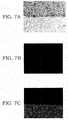
- FIGS. 7A to 7C show scanning electron microscope photographs of the joint interface between the bulk material 30 and the bulk material 31 joined under the heat treatment conditions and pressure application conditions shown in FIG. 4 .
- FIG. 7A is a secondary electron image
- FIG. 7B is a mapping image of FeL ⁇ obtained through EDX analysis
- FIG. 7C is a mapping image of CuL ⁇ obtained through EDX analysis.
- the upper side of the photographs shows the SCM435 and the lower side of the photographs shows the Cu-Ni based alloy.
- the two materials can be joined directly by a solid phase reaction caused by generating spark plasma on the joint interface while applying a pressing force thereto.
- a solid phase reaction caused by generating spark plasma on the joint interface while applying a pressing force thereto.
- FIG. 7 formation of a columnar configuration on the joint interface was not confirmed. The reason for this is believed to be that the diffusion constant of Ni in Cu is smaller than that of Zn, and therefore diffusion is less likely to occur even when a large amount of energy is applied through spark plasma application.
- the joint strength of the bulk material 30 and the bulk material 31 will be described.
- the joint strength was evaluated in a peel test performed by pulling the joined bulk material 30 and bulk material 31 in opposite directions and measuring the peel strength at a point where the bulk material 30 and the bulk material 31 peeled away from each other.
- Table 6 shows results of the peel test.
- the joint strength of the bulk material 30 and the bulk material 31 is equal to the joint strength of the comparative material shown in Table 3.
- a solid phase joint can likewise be formed between the SCM435 and the Cu-Ni based alloy directly without inserting a binder such as plating.
- a bulk material made of an iron based metal and a bulk material made of a Cu alloy can be joined easily and with a high degree of joint strength.
- the shoe 10 is coupled to the tip end of the piston 5 to be free to rotate via the spherically-shaped spherical washer 11.
- a spherical portion may be provided on the tip end of the piston 5 and a recessed spherical washer may be provided in the main body portion 13 of the shoe 10 such that the shoe 10 is coupled to the spherical portion on the tip end of the piston 5 to be free to rotate via the recessed spherical washer.
- the shoe 10 of a swash plate type piston pump motor serves as a sliding member according to the present invention.
- the sliding member is not limited thereto, and may be a slide bearing that supports a shaft.
- a sliding member manufactured using the method of manufacturing a sliding member having a sliding portion according to the present invention may be applied to a shoe of a piston pump motor.
Landscapes
- Engineering & Computer Science (AREA)
- Mechanical Engineering (AREA)
- Chemical & Material Sciences (AREA)
- Materials Engineering (AREA)
- Metallurgy (AREA)
- Organic Chemistry (AREA)
- Manufacturing & Machinery (AREA)
- General Engineering & Computer Science (AREA)
- Physics & Mathematics (AREA)
- Composite Materials (AREA)
- Plasma & Fusion (AREA)
- Optics & Photonics (AREA)
- Reciprocating Pumps (AREA)
- Powder Metallurgy (AREA)
- Pressure Welding/Diffusion-Bonding (AREA)
- Details Of Reciprocating Pumps (AREA)
Applications Claiming Priority (2)
| Application Number | Priority Date | Filing Date | Title |
|---|---|---|---|
| JP2011045554A JP5706193B2 (ja) | 2011-03-02 | 2011-03-02 | 摺動部材の製造方法 |
| PCT/JP2012/054219 WO2012117908A1 (ja) | 2011-03-02 | 2012-02-22 | 摺動部材の製造方法 |
Publications (3)
| Publication Number | Publication Date |
|---|---|
| EP2682217A1 EP2682217A1 (en) | 2014-01-08 |
| EP2682217A4 EP2682217A4 (en) | 2015-06-03 |
| EP2682217B1 true EP2682217B1 (en) | 2017-05-10 |
Family
ID=46757847
Family Applications (1)
| Application Number | Title | Priority Date | Filing Date |
|---|---|---|---|
| EP12752662.2A Active EP2682217B1 (en) | 2011-03-02 | 2012-02-22 | Method for fabricating slidable member |
Country Status (7)
Families Citing this family (9)
| Publication number | Priority date | Publication date | Assignee | Title |
|---|---|---|---|---|
| JP6027825B2 (ja) * | 2012-09-12 | 2016-11-16 | 株式会社タカコ | 摺動部材の製造方法 |
| WO2015056315A1 (ja) * | 2013-10-16 | 2015-04-23 | 株式会社小松製作所 | 摺動部品、摺動部品の製造方法および摺動部品の製造装置 |
| CN104014921B (zh) * | 2014-04-25 | 2016-04-27 | 长安大学 | 一种快速制备铜钼多层复合材料的方法 |
| JP5939590B2 (ja) * | 2014-06-30 | 2016-06-22 | 株式会社日本製鋼所 | 高硬度高熱伝導性複合金属材、高硬度高熱伝導性複合金属材の製造方法およびプラスチックまたは繊維強化プラスチック成形用金型 |
| CN104400339B (zh) * | 2014-10-28 | 2017-02-15 | 东莞市中一合金科技有限公司 | 连续条复焊料带材加工工艺及焊料带材 |
| JP6367476B2 (ja) | 2015-04-15 | 2018-08-01 | 株式会社小松製作所 | 摺動部品およびその製造方法 |
| KR101814665B1 (ko) * | 2016-07-26 | 2018-01-04 | 주식회사대영금속 | 방전 플라즈마를 이용한 이종복합소재의 제조 및 접합방법 |
| CN112091211B (zh) * | 2020-08-20 | 2021-09-10 | 上海交通大学 | 一种扩散多元节的制备方法 |
| JP7649009B2 (ja) | 2021-06-30 | 2025-03-19 | 株式会社明石合銅 | 複合摺動部品及びその製造方法 |
Family Cites Families (23)
| Publication number | Priority date | Publication date | Assignee | Title |
|---|---|---|---|---|
| EP0389625A1 (en) * | 1988-02-29 | 1990-10-03 | Kabushiki Kaisha Komatsu Seisakusho | Process for resistance diffusion junction |
| JPH0677829B2 (ja) * | 1988-08-19 | 1994-10-05 | 株式会社小松製作所 | 摺動部品の製造方法 |
| JP3325033B2 (ja) * | 1991-12-03 | 2002-09-17 | オイレス工業株式会社 | 複層焼結摺動部材ならびにその製造方法 |
| DE4411762A1 (de) * | 1994-04-06 | 1995-10-12 | Kolbenschmidt Ag | Gleitlagerwerkstoff |
| JPH10196552A (ja) * | 1997-01-16 | 1998-07-31 | Komatsu Ltd | 焼結接合シリンダブロック |
| JP4100583B2 (ja) * | 1997-08-25 | 2008-06-11 | 中越合金鋳工株式会社 | 鉄系材料と高力黄銅合金を接合する方法 |
| JPH11158514A (ja) * | 1997-11-25 | 1999-06-15 | Matsushita Electric Works Ltd | 金属バルク材の接合方法及び金属バルク材の接合体 |
| JP2000230476A (ja) * | 1999-02-08 | 2000-08-22 | Hitachi Constr Mach Co Ltd | 斜板式液圧回転機 |
| JP3548509B2 (ja) * | 2000-06-07 | 2004-07-28 | 諏訪熱工業株式会社 | パルス通電接合方法及び接合装置並びに接合体 |
| JP3857535B2 (ja) * | 2001-03-21 | 2006-12-13 | 独立行政法人科学技術振興機構 | 非晶質合金材料のパルス通電接合方法 |
| JP4080716B2 (ja) * | 2001-09-28 | 2008-04-23 | Spsシンテックス株式会社 | 小接合面用パルス通電接合方法 |
| JP4301761B2 (ja) * | 2002-03-08 | 2009-07-22 | 昌雄 本藤 | パルス通電による接合装置 |
| JP3737989B2 (ja) * | 2002-05-17 | 2006-01-25 | 昌雄 本藤 | パルス通電による部材の接合方法 |
| EP1508693B1 (en) * | 2003-08-18 | 2015-08-12 | Senju Metal Industry Co., Ltd. | Multi layer sliding part and a method for its manufacture |
| JP2005257035A (ja) | 2004-03-15 | 2005-09-22 | Kayaba Ind Co Ltd | 多層軸受材料 |
| CN100415910C (zh) * | 2006-09-08 | 2008-09-03 | 北京科技大学 | 用放电等离子烧结技术制备储氢合金的方法 |
| FR2906242B1 (fr) * | 2006-09-27 | 2009-01-16 | Commissariat Energie Atomique | Procede d'assemblage de pieces en ceramique refractaire par frittage a chaud avec champ electrique pulse ("sps") |
| JP4849462B2 (ja) * | 2006-11-15 | 2012-01-11 | 日立粉末冶金株式会社 | 複合焼結機械部品の製造方法およびシリンダブロック |
| JP4533401B2 (ja) * | 2007-05-14 | 2010-09-01 | Spsシンテックス株式会社 | 小接合面用パルス通電接合装置 |
| JP5132685B2 (ja) * | 2007-11-08 | 2013-01-30 | 相田化学工業株式会社 | 金属熱成形体、その製造方法、及び模様金属板材の製造方法 |
| CN201374833Y (zh) * | 2009-03-02 | 2009-12-30 | 深圳大学 | 一种复合电极压头及放电等离子烧结设备 |
| CN101733623B (zh) * | 2009-12-10 | 2012-05-09 | 北京科技大学 | 一种金属层状复合材料放电等离子体制备方法 |
| JP5585984B2 (ja) * | 2010-07-27 | 2014-09-10 | 独立行政法人 宇宙航空研究開発機構 | パルス通電接合方法及びパルス通電接合装置 |
-
2011
- 2011-03-02 JP JP2011045554A patent/JP5706193B2/ja active Active
-
2012
- 2012-02-22 WO PCT/JP2012/054219 patent/WO2012117908A1/ja active Application Filing
- 2012-02-22 CN CN2012800110852A patent/CN103402690A/zh active Pending
- 2012-02-22 US US14/002,655 patent/US20130333200A1/en not_active Abandoned
- 2012-02-22 EP EP12752662.2A patent/EP2682217B1/en active Active
- 2012-02-22 KR KR20137025466A patent/KR20140010101A/ko not_active Ceased
- 2012-03-01 TW TW101106628A patent/TWI554352B/zh active
Also Published As
| Publication number | Publication date |
|---|---|
| KR20140010101A (ko) | 2014-01-23 |
| JP2012179649A (ja) | 2012-09-20 |
| WO2012117908A1 (ja) | 2012-09-07 |
| TWI554352B (zh) | 2016-10-21 |
| US20130333200A1 (en) | 2013-12-19 |
| JP5706193B2 (ja) | 2015-04-22 |
| EP2682217A1 (en) | 2014-01-08 |
| TW201300185A (zh) | 2013-01-01 |
| CN103402690A (zh) | 2013-11-20 |
| EP2682217A4 (en) | 2015-06-03 |
Similar Documents
| Publication | Publication Date | Title |
|---|---|---|
| EP2682217B1 (en) | Method for fabricating slidable member | |
| EP2184121B1 (en) | Multi-layered sintered slide member | |
| JP5091120B2 (ja) | 滑り軸受け複合材料、使用及び製造法 | |
| JP5284083B2 (ja) | 滑り軸受け複合材料、使用及び製造法 | |
| JP2008540982A (ja) | 特に航空機動力伝達装置における高負荷転がり軸受用の転がり軸受レース及びその製造方法 | |
| JPH03177598A (ja) | すべり軸受 | |
| EP3026141A1 (en) | Valve guide made from sintered alloy, and method for producing same | |
| CN102205416A (zh) | 一种发动机挺柱的制造方法 | |
| CN112553498B (zh) | 一种铜-球墨铸铁双金属液压耐磨部件及其制备方法 | |
| KR20190018425A (ko) | 스퍼터링 타깃의 제조 방법 및 스퍼터링 타깃 | |
| Kundu et al. | Interfacial reaction and microstructure study of DSS/Cu/Ti64 diffusion-welded couple | |
| Kundu et al. | Diffusion welding of Ti6Al4V and 17-4 stainless steel using Cu/Ni microlayers | |
| Huang et al. | Fabrication and evaluation of electroplated diamond grinding rods strengthened with Cr-C deposit | |
| KR101370508B1 (ko) | 복합소결구조의 원통형 오일리스 슬라이딩 베어링의 제조 방법 | |
| CN1057244C (zh) | 一种钢-铜铅合金双金属柱塞缸体的制造方法 | |
| WO2014042161A1 (ja) | 摺動部材の製造方法 | |
| CN106637093A (zh) | 多元多层纳米膜粉末冶金气门座及其制备方法 | |
| JP4383837B2 (ja) | 金属基複合材料の製造方法及びその方法で製造された複合材料 | |
| JPH1030137A (ja) | 銅系摺動部材 | |
| EP2778409A1 (en) | Sliding members and piston pump motor | |
| CN116288340A (zh) | 一种铜合金-球墨铸铁双金属耐磨减摩板及其制备方法 | |
| JP2015121328A (ja) | 摺動部材の製造方法 | |
| JP2019100350A (ja) | 摺動部材 | |
| JP3764807B2 (ja) | プレス成形用複合金型材およびその製造方法、並びに該複合金型材からなるプレス成形用金型 | |
| JPH07256445A (ja) | 銅合金のライニング方法 |
Legal Events
| Date | Code | Title | Description |
|---|---|---|---|
| PUAI | Public reference made under article 153(3) epc to a published international application that has entered the european phase |
Free format text: ORIGINAL CODE: 0009012 |
|
| 17P | Request for examination filed |
Effective date: 20131002 |
|
| AK | Designated contracting states |
Kind code of ref document: A1 Designated state(s): AL AT BE BG CH CY CZ DE DK EE ES FI FR GB GR HR HU IE IS IT LI LT LU LV MC MK MT NL NO PL PT RO RS SE SI SK SM TR |
|
| DAX | Request for extension of the european patent (deleted) | ||
| RA4 | Supplementary search report drawn up and despatched (corrected) |
Effective date: 20150507 |
|
| RIC1 | Information provided on ipc code assigned before grant |
Ipc: C22C 1/02 20060101ALI20150605BHEP Ipc: B23K 20/00 20060101AFI20150605BHEP Ipc: C22C 9/02 20060101ALI20150605BHEP Ipc: C22C 9/01 20060101ALI20150605BHEP Ipc: B23P 15/00 20060101ALI20150605BHEP Ipc: B23K 10/02 20060101ALI20150605BHEP Ipc: B22F 7/02 20060101ALI20150605BHEP Ipc: B23K 35/00 20060101ALI20150605BHEP Ipc: B22F 3/14 20060101ALI20150605BHEP Ipc: B32B 15/01 20060101ALI20150605BHEP Ipc: B22F 7/08 20060101ALI20150605BHEP Ipc: B22F 3/105 20060101ALI20150605BHEP Ipc: C22C 9/04 20060101ALI20150605BHEP Ipc: B22F 5/00 20060101ALI20150605BHEP Ipc: C22C 9/06 20060101ALI20150605BHEP Ipc: C22C 1/04 20060101ALI20150605BHEP Ipc: C22C 9/08 20060101ALI20150605BHEP |
|
| 17Q | First examination report despatched |
Effective date: 20160504 |
|
| GRAP | Despatch of communication of intention to grant a patent |
Free format text: ORIGINAL CODE: EPIDOSNIGR1 |
|
| RIC1 | Information provided on ipc code assigned before grant |
Ipc: C22C 38/22 20060101ALI20161123BHEP Ipc: B23K 20/00 20060101AFI20161123BHEP Ipc: F04B 53/14 20060101ALI20161123BHEP Ipc: B23P 15/00 20060101ALI20161123BHEP Ipc: C22C 38/18 20060101ALI20161123BHEP Ipc: C22C 1/02 20060101ALI20161123BHEP Ipc: F04B 1/12 20060101ALI20161123BHEP Ipc: B22F 5/00 20060101ALI20161123BHEP Ipc: B32B 15/01 20060101ALI20161123BHEP Ipc: C22C 9/01 20060101ALI20161123BHEP Ipc: F04B 1/20 20060101ALI20161123BHEP Ipc: B22F 7/02 20060101ALI20161123BHEP Ipc: B22F 7/08 20060101ALI20161123BHEP Ipc: C22C 38/02 20060101ALI20161123BHEP Ipc: B22F 3/14 20060101ALI20161123BHEP Ipc: B22F 3/105 20060101ALI20161123BHEP Ipc: B23K 10/02 20060101ALI20161123BHEP |
|
| INTG | Intention to grant announced |
Effective date: 20161216 |
|
| GRAS | Grant fee paid |
Free format text: ORIGINAL CODE: EPIDOSNIGR3 |
|
| GRAA | (expected) grant |
Free format text: ORIGINAL CODE: 0009210 |
|
| RAP1 | Party data changed (applicant data changed or rights of an application transferred) |
Owner name: TAKAKO INDUSTRIES, INC. |
|
| AK | Designated contracting states |
Kind code of ref document: B1 Designated state(s): AL AT BE BG CH CY CZ DE DK EE ES FI FR GB GR HR HU IE IS IT LI LT LU LV MC MK MT NL NO PL PT RO RS SE SI SK SM TR |
|
| REG | Reference to a national code |
Ref country code: GB Ref legal event code: FG4D |
|
| REG | Reference to a national code |
Ref country code: AT Ref legal event code: REF Ref document number: 891785 Country of ref document: AT Kind code of ref document: T Effective date: 20170515 Ref country code: CH Ref legal event code: EP Ref country code: CH Ref legal event code: NV Representative=s name: BOVARD AG PATENT- UND MARKENANWAELTE, CH |
|
| REG | Reference to a national code |
Ref country code: IE Ref legal event code: FG4D |
|
| REG | Reference to a national code |
Ref country code: DE Ref legal event code: R096 Ref document number: 602012032269 Country of ref document: DE |
|
| REG | Reference to a national code |
Ref country code: NL Ref legal event code: MP Effective date: 20170510 |
|
| REG | Reference to a national code |
Ref country code: LT Ref legal event code: MG4D |
|
| REG | Reference to a national code |
Ref country code: AT Ref legal event code: MK05 Ref document number: 891785 Country of ref document: AT Kind code of ref document: T Effective date: 20170510 |
|
| PG25 | Lapsed in a contracting state [announced via postgrant information from national office to epo] |
Ref country code: ES Free format text: LAPSE BECAUSE OF FAILURE TO SUBMIT A TRANSLATION OF THE DESCRIPTION OR TO PAY THE FEE WITHIN THE PRESCRIBED TIME-LIMIT Effective date: 20170510 Ref country code: LT Free format text: LAPSE BECAUSE OF FAILURE TO SUBMIT A TRANSLATION OF THE DESCRIPTION OR TO PAY THE FEE WITHIN THE PRESCRIBED TIME-LIMIT Effective date: 20170510 Ref country code: FI Free format text: LAPSE BECAUSE OF FAILURE TO SUBMIT A TRANSLATION OF THE DESCRIPTION OR TO PAY THE FEE WITHIN THE PRESCRIBED TIME-LIMIT Effective date: 20170510 Ref country code: AT Free format text: LAPSE BECAUSE OF FAILURE TO SUBMIT A TRANSLATION OF THE DESCRIPTION OR TO PAY THE FEE WITHIN THE PRESCRIBED TIME-LIMIT Effective date: 20170510 Ref country code: GR Free format text: LAPSE BECAUSE OF FAILURE TO SUBMIT A TRANSLATION OF THE DESCRIPTION OR TO PAY THE FEE WITHIN THE PRESCRIBED TIME-LIMIT Effective date: 20170811 Ref country code: NO Free format text: LAPSE BECAUSE OF FAILURE TO SUBMIT A TRANSLATION OF THE DESCRIPTION OR TO PAY THE FEE WITHIN THE PRESCRIBED TIME-LIMIT Effective date: 20170810 Ref country code: HR Free format text: LAPSE BECAUSE OF FAILURE TO SUBMIT A TRANSLATION OF THE DESCRIPTION OR TO PAY THE FEE WITHIN THE PRESCRIBED TIME-LIMIT Effective date: 20170510 |
|
| PG25 | Lapsed in a contracting state [announced via postgrant information from national office to epo] |
Ref country code: BG Free format text: LAPSE BECAUSE OF FAILURE TO SUBMIT A TRANSLATION OF THE DESCRIPTION OR TO PAY THE FEE WITHIN THE PRESCRIBED TIME-LIMIT Effective date: 20170810 Ref country code: SE Free format text: LAPSE BECAUSE OF FAILURE TO SUBMIT A TRANSLATION OF THE DESCRIPTION OR TO PAY THE FEE WITHIN THE PRESCRIBED TIME-LIMIT Effective date: 20170510 Ref country code: RS Free format text: LAPSE BECAUSE OF FAILURE TO SUBMIT A TRANSLATION OF THE DESCRIPTION OR TO PAY THE FEE WITHIN THE PRESCRIBED TIME-LIMIT Effective date: 20170510 Ref country code: IS Free format text: LAPSE BECAUSE OF FAILURE TO SUBMIT A TRANSLATION OF THE DESCRIPTION OR TO PAY THE FEE WITHIN THE PRESCRIBED TIME-LIMIT Effective date: 20170910 Ref country code: PL Free format text: LAPSE BECAUSE OF FAILURE TO SUBMIT A TRANSLATION OF THE DESCRIPTION OR TO PAY THE FEE WITHIN THE PRESCRIBED TIME-LIMIT Effective date: 20170510 Ref country code: LV Free format text: LAPSE BECAUSE OF FAILURE TO SUBMIT A TRANSLATION OF THE DESCRIPTION OR TO PAY THE FEE WITHIN THE PRESCRIBED TIME-LIMIT Effective date: 20170510 Ref country code: NL Free format text: LAPSE BECAUSE OF FAILURE TO SUBMIT A TRANSLATION OF THE DESCRIPTION OR TO PAY THE FEE WITHIN THE PRESCRIBED TIME-LIMIT Effective date: 20170510 |
|
| PG25 | Lapsed in a contracting state [announced via postgrant information from national office to epo] |
Ref country code: RO Free format text: LAPSE BECAUSE OF FAILURE TO SUBMIT A TRANSLATION OF THE DESCRIPTION OR TO PAY THE FEE WITHIN THE PRESCRIBED TIME-LIMIT Effective date: 20170510 Ref country code: DK Free format text: LAPSE BECAUSE OF FAILURE TO SUBMIT A TRANSLATION OF THE DESCRIPTION OR TO PAY THE FEE WITHIN THE PRESCRIBED TIME-LIMIT Effective date: 20170510 Ref country code: EE Free format text: LAPSE BECAUSE OF FAILURE TO SUBMIT A TRANSLATION OF THE DESCRIPTION OR TO PAY THE FEE WITHIN THE PRESCRIBED TIME-LIMIT Effective date: 20170510 Ref country code: CZ Free format text: LAPSE BECAUSE OF FAILURE TO SUBMIT A TRANSLATION OF THE DESCRIPTION OR TO PAY THE FEE WITHIN THE PRESCRIBED TIME-LIMIT Effective date: 20170510 Ref country code: SK Free format text: LAPSE BECAUSE OF FAILURE TO SUBMIT A TRANSLATION OF THE DESCRIPTION OR TO PAY THE FEE WITHIN THE PRESCRIBED TIME-LIMIT Effective date: 20170510 |
|
| REG | Reference to a national code |
Ref country code: DE Ref legal event code: R097 Ref document number: 602012032269 Country of ref document: DE |
|
| REG | Reference to a national code |
Ref country code: FR Ref legal event code: PLFP Year of fee payment: 7 |
|
| PG25 | Lapsed in a contracting state [announced via postgrant information from national office to epo] |
Ref country code: SM Free format text: LAPSE BECAUSE OF FAILURE TO SUBMIT A TRANSLATION OF THE DESCRIPTION OR TO PAY THE FEE WITHIN THE PRESCRIBED TIME-LIMIT Effective date: 20170510 |
|
| PLBE | No opposition filed within time limit |
Free format text: ORIGINAL CODE: 0009261 |
|
| STAA | Information on the status of an ep patent application or granted ep patent |
Free format text: STATUS: NO OPPOSITION FILED WITHIN TIME LIMIT |
|
| 26N | No opposition filed |
Effective date: 20180213 |
|
| PG25 | Lapsed in a contracting state [announced via postgrant information from national office to epo] |
Ref country code: SI Free format text: LAPSE BECAUSE OF FAILURE TO SUBMIT A TRANSLATION OF THE DESCRIPTION OR TO PAY THE FEE WITHIN THE PRESCRIBED TIME-LIMIT Effective date: 20170510 |
|
| PG25 | Lapsed in a contracting state [announced via postgrant information from national office to epo] |
Ref country code: MC Free format text: LAPSE BECAUSE OF FAILURE TO SUBMIT A TRANSLATION OF THE DESCRIPTION OR TO PAY THE FEE WITHIN THE PRESCRIBED TIME-LIMIT Effective date: 20170510 |
|
| GBPC | Gb: european patent ceased through non-payment of renewal fee |
Effective date: 20180222 |
|
| REG | Reference to a national code |
Ref country code: IE Ref legal event code: MM4A |
|
| REG | Reference to a national code |
Ref country code: BE Ref legal event code: MM Effective date: 20180228 |
|
| PG25 | Lapsed in a contracting state [announced via postgrant information from national office to epo] |
Ref country code: LU Free format text: LAPSE BECAUSE OF NON-PAYMENT OF DUE FEES Effective date: 20180222 |
|
| PG25 | Lapsed in a contracting state [announced via postgrant information from national office to epo] |
Ref country code: IE Free format text: LAPSE BECAUSE OF NON-PAYMENT OF DUE FEES Effective date: 20180222 |
|
| PG25 | Lapsed in a contracting state [announced via postgrant information from national office to epo] |
Ref country code: BE Free format text: LAPSE BECAUSE OF NON-PAYMENT OF DUE FEES Effective date: 20180228 Ref country code: GB Free format text: LAPSE BECAUSE OF NON-PAYMENT OF DUE FEES Effective date: 20180222 |
|
| PG25 | Lapsed in a contracting state [announced via postgrant information from national office to epo] |
Ref country code: MT Free format text: LAPSE BECAUSE OF NON-PAYMENT OF DUE FEES Effective date: 20180222 |
|
| PG25 | Lapsed in a contracting state [announced via postgrant information from national office to epo] |
Ref country code: TR Free format text: LAPSE BECAUSE OF FAILURE TO SUBMIT A TRANSLATION OF THE DESCRIPTION OR TO PAY THE FEE WITHIN THE PRESCRIBED TIME-LIMIT Effective date: 20170510 |
|
| PG25 | Lapsed in a contracting state [announced via postgrant information from national office to epo] |
Ref country code: PT Free format text: LAPSE BECAUSE OF FAILURE TO SUBMIT A TRANSLATION OF THE DESCRIPTION OR TO PAY THE FEE WITHIN THE PRESCRIBED TIME-LIMIT Effective date: 20170510 Ref country code: HU Free format text: LAPSE BECAUSE OF FAILURE TO SUBMIT A TRANSLATION OF THE DESCRIPTION OR TO PAY THE FEE WITHIN THE PRESCRIBED TIME-LIMIT; INVALID AB INITIO Effective date: 20120222 |
|
| PG25 | Lapsed in a contracting state [announced via postgrant information from national office to epo] |
Ref country code: MK Free format text: LAPSE BECAUSE OF NON-PAYMENT OF DUE FEES Effective date: 20170510 Ref country code: CY Free format text: LAPSE BECAUSE OF FAILURE TO SUBMIT A TRANSLATION OF THE DESCRIPTION OR TO PAY THE FEE WITHIN THE PRESCRIBED TIME-LIMIT Effective date: 20170510 |
|
| PG25 | Lapsed in a contracting state [announced via postgrant information from national office to epo] |
Ref country code: AL Free format text: LAPSE BECAUSE OF FAILURE TO SUBMIT A TRANSLATION OF THE DESCRIPTION OR TO PAY THE FEE WITHIN THE PRESCRIBED TIME-LIMIT Effective date: 20170510 |
|
| PGFP | Annual fee paid to national office [announced via postgrant information from national office to epo] |
Ref country code: DE Payment date: 20250218 Year of fee payment: 14 |
|
| PGFP | Annual fee paid to national office [announced via postgrant information from national office to epo] |
Ref country code: CH Payment date: 20250301 Year of fee payment: 14 |
|
| PGFP | Annual fee paid to national office [announced via postgrant information from national office to epo] |
Ref country code: FR Payment date: 20250221 Year of fee payment: 14 |
|
| PGFP | Annual fee paid to national office [announced via postgrant information from national office to epo] |
Ref country code: IT Payment date: 20250224 Year of fee payment: 14 |