EP2678507B1 - Glasschiebetür - Google Patents
Glasschiebetür Download PDFInfo
- Publication number
- EP2678507B1 EP2678507B1 EP12701154.2A EP12701154A EP2678507B1 EP 2678507 B1 EP2678507 B1 EP 2678507B1 EP 12701154 A EP12701154 A EP 12701154A EP 2678507 B1 EP2678507 B1 EP 2678507B1
- Authority
- EP
- European Patent Office
- Prior art keywords
- end position
- damping unit
- sliding door
- glass pane
- limiting device
- Prior art date
- Legal status (The legal status is an assumption and is not a legal conclusion. Google has not performed a legal analysis and makes no representation as to the accuracy of the status listed.)
- Active
Links
Images
Classifications
-
- E—FIXED CONSTRUCTIONS
- E05—LOCKS; KEYS; WINDOW OR DOOR FITTINGS; SAFES
- E05F—DEVICES FOR MOVING WINGS INTO OPEN OR CLOSED POSITION; CHECKS FOR WINGS; WING FITTINGS NOT OTHERWISE PROVIDED FOR, CONCERNED WITH THE FUNCTIONING OF THE WING
- E05F5/00—Braking devices, e.g. checks; Stops; Buffers
- E05F5/003—Braking devices, e.g. checks; Stops; Buffers for sliding wings
-
- E—FIXED CONSTRUCTIONS
- E05—LOCKS; KEYS; WINDOW OR DOOR FITTINGS; SAFES
- E05F—DEVICES FOR MOVING WINGS INTO OPEN OR CLOSED POSITION; CHECKS FOR WINGS; WING FITTINGS NOT OTHERWISE PROVIDED FOR, CONCERNED WITH THE FUNCTIONING OF THE WING
- E05F1/00—Closers or openers for wings, not otherwise provided for in this subclass
- E05F1/08—Closers or openers for wings, not otherwise provided for in this subclass spring-actuated, e.g. for horizontally sliding wings
- E05F1/16—Closers or openers for wings, not otherwise provided for in this subclass spring-actuated, e.g. for horizontally sliding wings for sliding wings
-
- E—FIXED CONSTRUCTIONS
- E05—LOCKS; KEYS; WINDOW OR DOOR FITTINGS; SAFES
- E05D—HINGES OR SUSPENSION DEVICES FOR DOORS, WINDOWS OR WINGS
- E05D15/00—Suspension arrangements for wings
- E05D15/06—Suspension arrangements for wings for wings sliding horizontally more or less in their own plane
- E05D15/0621—Details, e.g. suspension or supporting guides
- E05D15/0626—Details, e.g. suspension or supporting guides for wings suspended at the top
- E05D15/063—Details, e.g. suspension or supporting guides for wings suspended at the top on wheels with fixed axis
-
- E—FIXED CONSTRUCTIONS
- E05—LOCKS; KEYS; WINDOW OR DOOR FITTINGS; SAFES
- E05Y—INDEXING SCHEME ASSOCIATED WITH SUBCLASSES E05D AND E05F, RELATING TO CONSTRUCTION ELEMENTS, ELECTRIC CONTROL, POWER SUPPLY, POWER SIGNAL OR TRANSMISSION, USER INTERFACES, MOUNTING OR COUPLING, DETAILS, ACCESSORIES, AUXILIARY OPERATIONS NOT OTHERWISE PROVIDED FOR, APPLICATION THEREOF
- E05Y2600/00—Mounting or coupling arrangements for elements provided for in this subclass
- E05Y2600/40—Mounting location; Visibility of the elements
- E05Y2600/45—Mounting location; Visibility of the elements in or on the fixed frame
-
- E—FIXED CONSTRUCTIONS
- E05—LOCKS; KEYS; WINDOW OR DOOR FITTINGS; SAFES
- E05Y—INDEXING SCHEME ASSOCIATED WITH SUBCLASSES E05D AND E05F, RELATING TO CONSTRUCTION ELEMENTS, ELECTRIC CONTROL, POWER SUPPLY, POWER SIGNAL OR TRANSMISSION, USER INTERFACES, MOUNTING OR COUPLING, DETAILS, ACCESSORIES, AUXILIARY OPERATIONS NOT OTHERWISE PROVIDED FOR, APPLICATION THEREOF
- E05Y2800/00—Details, accessories and auxiliary operations not otherwise provided for
- E05Y2800/20—Combinations of elements
- E05Y2800/22—Combinations of elements of not identical elements of the same category, e.g. combinations of not identical springs
-
- E—FIXED CONSTRUCTIONS
- E05—LOCKS; KEYS; WINDOW OR DOOR FITTINGS; SAFES
- E05Y—INDEXING SCHEME ASSOCIATED WITH SUBCLASSES E05D AND E05F, RELATING TO CONSTRUCTION ELEMENTS, ELECTRIC CONTROL, POWER SUPPLY, POWER SIGNAL OR TRANSMISSION, USER INTERFACES, MOUNTING OR COUPLING, DETAILS, ACCESSORIES, AUXILIARY OPERATIONS NOT OTHERWISE PROVIDED FOR, APPLICATION THEREOF
- E05Y2800/00—Details, accessories and auxiliary operations not otherwise provided for
- E05Y2800/20—Combinations of elements
- E05Y2800/23—Combinations of elements of elements of different categories
- E05Y2800/24—Combinations of elements of elements of different categories of springs and brakes
-
- E—FIXED CONSTRUCTIONS
- E05—LOCKS; KEYS; WINDOW OR DOOR FITTINGS; SAFES
- E05Y—INDEXING SCHEME ASSOCIATED WITH SUBCLASSES E05D AND E05F, RELATING TO CONSTRUCTION ELEMENTS, ELECTRIC CONTROL, POWER SUPPLY, POWER SIGNAL OR TRANSMISSION, USER INTERFACES, MOUNTING OR COUPLING, DETAILS, ACCESSORIES, AUXILIARY OPERATIONS NOT OTHERWISE PROVIDED FOR, APPLICATION THEREOF
- E05Y2900/00—Application of doors, windows, wings or fittings thereof
- E05Y2900/10—Application of doors, windows, wings or fittings thereof for buildings or parts thereof
- E05Y2900/13—Type of wing
- E05Y2900/132—Doors
Definitions
- the invention relates to a sliding glass door, with a door, which is guided with a drive in a track rail, limiting the path of the door leaf limiting device, a damper unit with retracting function and a coupler, which engages with an engaging portion of the damper detent, wherein the damper unit the door leaf initially decelerates in the process towards an end position and then drives into the end position.
- damper which slows down the closing movement before reaching the end stop, so that a hard hitting the door leaf against the end stop is avoided.
- the damper absorbs the kinetic energy of the door leaf during the closing movement of the sliding door.
- dampers are known which are additionally equipped with a spring which draws the engaging part of the damper in the direction of the damper end position.
- JP 2003 214023 A discloses a display case with sliding glass doors each having a retracting lock mechanism in which a coupler of a drive latchingly engages an engaging member, the coupler being disposed on the portion of the drive cooperating with a restrictor and centered on the drive.
- the invention is therefore based on the object to further develop the known from the prior art sliding door, so that the risk of malfunction is avoided by deforming the coupler, at the same time a compact design of the drive is made possible.
- Invention is a simple assembly of the sliding door are made possible, with a faulty arrangement of damper unit, coupler and limiting device is virtually impossible.
- the sliding glass door according to the present invention is defined by claim 1.
- the invention provides a sliding glass door with a running rail, one on it with at least one drive guided door and a limitation of the path of the door limiting device, a damper unit with retraction function and a coupler, which engages detent with an engaging portion of the damper unit, before, wherein the damper unit slows down the door during the process toward an end position and then in the end position is driving.
- the invention is characterized in that the coupler is arranged at the rear end in the direction of the end position on the drive.
- the coupler is disposed on the drive at the rear end of the drive toward the end position.
- the coupler is at the rear end of the drive.
- the drive is thus moved to a large extent in the region of the damper unit.
- the damper unit thus exerts a pulling movement on the drive.
- the drive is pushed by the damper unit in the end position.
- the inventive design of the drive a very compact drive.
- the construction according to the invention moreover makes it possible for the drive to be fastened to the door leaf in such a way that the roller is arranged very close to a lateral edge of the door leaf, thereby enabling a particularly advantageous guidance of the door leaf. In this case, no projection of the drive to the door is necessary. In addition, can even the door leaf projecting beyond the drive in the direction of the end position, so that in the end position the door leaf is flush with the running rail. This is possible, for example, by the limiting device cooperating with a part of the drive, which is arranged laterally of the door leaf.
- a sliding door according to the invention it is possible for a sliding door according to the invention that two drives according to the invention are attached to a door leaf, wherein these are arranged mirror-inverted.
- a first damper unit also mirror-inverted arranged second damper unit is thus allowed that the door leaf of the sliding door according to the invention in the process in both end positions, i. both the closed position and the open position, braked and guided accordingly.
- an advantageous guidance of the door leaf is possible because the drives can be arranged widely spaced due to the compact design.
- a development of the invention provides that the damper unit and the limiting device have mutually adapted positioning elements for the defined positioning of the limiting device on the damper unit.
- the damper unit can first be mounted in the running rail in a simple manner, before the limiting device can be fastened to the running rail at a position defined by the positioning elements relative to the damper unit.
- the drive has a length which is less than the length of the damper unit, wherein the drive in the End position is completely in the region of the running rail, in which the damper unit is arranged.
- the damper unit has a sufficient size to accommodate the necessary for a reliable damping and collection function of the door leaf elements.
- the invention provides that the limiting device has a first stop surface and the drive at the end facing in the direction of the end position, a second stop surface which abut each other in the end position.
- the provision of two stop surfaces makes it possible to limit the movement of the drive in a particularly advantageous manner.
- stop buffers may be provided on one or both stop surfaces, which cause a gentle impact of the drive on the limiting device.
- the distance in the longitudinal direction of the running rail between the engaging part of the damper unit in a damper end position and the first stop surface of the limiting device corresponds to the distance in the longitudinal direction of the running rail between the coupler and the second stop surface of the drive. In this way it can be ensured that upon reaching the previously defined damper end position, the drive strikes against the first stop surface of the limiting device with the second stop surface. It is provided that the damper end position is a position in which the damper unit is not fully retracted. This can prevent that before or when reaching the end position of the drive it comes to a striking of the damper unit. Due to the fact that the drive always strikes against the limiting device due to the construction according to the invention, before the damper unit is completely retracted, damage to the damper unit is avoided.
- the positioning elements of the damper unit and the limiting device have a shape adapted to one another. In this way, an arrangement of the limiting device to the damper unit in a defined position in a particularly simple manner possible.
- the positioning element of the limiting device is a dowel pin and the positioning element of the damper unit adapted to the dowel hole.
- Such positioning elements are manufactured in a particularly simple manner and errors in the assembly are avoided, since positioning elements can be brought together only in one way.
- positioning elements are used in a different form or that a dowel pin on the damper unit and a bore adapted to the dowel pin is arranged on the limiting device.
- a preferred embodiment of the invention provides that the coupler engages in a recess of the attack part of the Dämpfereihheit, wherein the coupler is preferably a protruding from the carriage nose.
- Such a configuration of the coupler has proven to be particularly advantageous.
- the nose formed as a coupler protrudes upwards from the drive, it is advantageous, since in the engaging into the recess of the engaging part a change in height of the drive, for example by a height adjustment of the drive, only leads to a displacement of the nose, so that slipping out of the coupler is prevented from the recess.
- a method of the drive over slight bumps thus does not lead to slipping out of the coupler part of the recess of the engaging part.
- the engaging part of the damper unit is guided in a slotted guide.
- a guide of the wantedteils is particularly advantageous because the orientation of the recess of the wantedteils can be changed via the slotted guide. As a result, a reliable engagement of the coupler is ensured with the engaging part during the damping and retraction phase by the damper unit.
- the engaging part of the damper unit is designed as a fork.
- the invention provided in the recess recess can be formed in a simple manner.
- the trained as a fork engaging part can be designed to be pivotable. It can be provided that, when moving the drive in the direction of the end position, the slide guide causes the pivoting of the fork from a starting position in a pivoted position and holds the fork in the pivoted position. When moving the drive from the end position, the slide guide can initially hold the fork in the pivoted position and cause the pivoting of the fork to reach the starting position.
- the slotted guide thus allows in a simple manner that the trained as a fork attacking part while moving the drive in the direction of the end position both absorb a force exerted by the drive force and transmitted to the damper unit and exerted during the collection function of the damper unit Force can transfer to the drive. Furthermore, the slotted guide allows the process of the drive from the end position, a force can be transmitted from the drive to the damper unit, so that a spring of the damper unit can be stretched.
- the damper unit can be arranged above or to the side of a track of the track rail.
- the damper unit comprises a piston-cylinder unit and a spring arranged parallel to the piston-cylinder unit.
- a damping function can be realized in a particularly advantageous manner.
- the arranged parallel to the piston-cylinder unit spring can cause the collection function of the damper unit.
- the damper unit may be individually and together with the limiting device on the running rail in the longitudinal direction to be displaced and locked.
- the sliding door according to the invention is particularly, but not exclusively, suitable as a sliding glass door.
- the drive is part of a metal upper bracket for the glass door leaf. Therefore, it is particularly advantageous if the assembly is mounted in total and in a simple manner in the correct mutual assignment of the components.
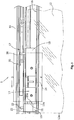
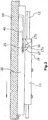
- a sliding door 1 is shown schematically.
- Fig. 1 shows a side view of the sliding door while Fig. 2 represents a top view.
- the sliding door 1 has a running rail 10, which is horizontally mounted on a door opening and a drive 13 leads, to which a door leaf 12 is suspended suspended.
- a drive 13 leads, to which a door leaf 12 is suspended suspended.
- two drives 13 are provided on the door leaf 12, of which only one is visible.
- the drives 13 are arranged mirror-inverted on the door leaf 12.
- the drives 13 have rollers 14, which are guided in a raceway 16 of the running rail 10 and roll there friction.
- a damper unit 20 is arranged with retraction function.
- a limiting device 15 which limits the travel path of the door leaf 12, is further fastened in the running rail 10.
- the damper unit 20 and the limiting device 15 have mutually adapted positioning elements.
- a dowel pin 23 is provided on the limiting device 15, which engages in a matched to the dowel pin 23 bore 22 in the damper unit 20.
- the positioning elements of the damper unit 20 and the limiting device 15 thus have a shape adapted to one another.
- the damper unit 20 has an engaging part 17 into which a coupler 30 of the drive 13 can engage with a detent.
- the engaging part 17 has a recess 25, in which the coupler 30, which is formed in the illustrated embodiment as from the drive 13 upwardly projecting nose, can intervene.
- the coupler 30 engages in the engaging part 17 of the damper unit 20.
- the damper unit 20 brakes the door leaf 12 first and then drives it into the in Fig. 1 shown end position.
- the damper unit 20 on a piston-cylinder unit, not shown, which causes a damping function and thus the braking of the door leaf.
- the damper unit 20 on a spring which drives the door leaf 12 by its spring force in the end position.
- the drive 13 is struck on the limiting device 15, so that a first stop surface 15a of the limiting device 15 rests against a second stop surface 13a of the drive 13.
- the first stop surface 15 a of the limiting device 15 is in the in Fig. 1 illustrated embodiment formed by a stop buffer 35, which may be formed for example as a rubber buffer.
- the coupler 30 is arranged on the drive 13 at the rear end 18 in the direction of the end position.
- the coupler 30 is thus arranged on the side facing away from the second stop surface 13a of the drive 13 side of the drive 13, so that it is prevented by striking the drive 13 on the limiting device 15 to a deformation of the coupler 30 or the rear end 18th that carries the coupler 30 may come.
- a distance d between the second stop surface 13a on the drive 13 and the coupler 30 is fixed.
- the distance d corresponds to the distance D between the engaging part 17 and the damper unit 20 in a damper end position and the first stop surface 15a of the limiting device 15.
- the distances d and D extend respectively in the longitudinal direction of. Running rail 10.
- the damper end position is the in the Fig. 1 shown position of the damper unit 20, wherein in this damper end position, the damper unit 20 is not fully retracted.
- Such a construction prevents the forces generated when striking the drive 13 to the limiting device 15 must be absorbed by the damper unit 20, so that damage to the damper unit 20 is prevented.
- the distances d and D are predetermined by design and are immutable by the distance d are given by the dimensions of the drive and the distance D is determined by the defined positioning of the limiting device 15 to the damper unit 20, it is ensured that the drive 13 basically only abuts against the limiting device 15.
- the door leaf 12 can project beyond the drive 1.3 in the direction of the end position, so that in the end position the door leaf 12 is flush with the running rail 10. This is particularly advantageous when mounting the sliding door 1 according to the invention adjacent to a wall.
- the limiting device 15 cooperates with a part of the drive 13, which is arranged laterally of the door leaf 12, so that a part of the door leaf is moved in the direction of observation via the limiting device 15.
- the engaging part 17 is formed as a fork.
- the engaging part 17 is initially in a starting position, in which the recess 25 extends substantially in the longitudinal direction of the running rail. This is the result Recess 25 in a position that the coupler 30 can engage in the recess 25 during the process of the drive.
- the engaging part 17 is pivoted.
- the engaging part 17 is guided in the damper unit 20 in a slotted guide 40, which causes the pivoting of the engaging part 17.
- the coupler 30 of the drive 13 abuts against the end part of the fork 17 a in the direction of the end position, so that a force is exerted by the drive 13 on the damper unit 20.
- the damper unit 20 now brakes the drive 13 by the damping function.
- the clamping force of existing in the damper unit 20 spring so that the engaging member 17 is pulled in the direction of the end position.
- the in the end position rear portion 17b of the engaging member 17 is now applied to the coupler 30 and exerts a force on the drive 13, so that this in the in Fig. 1 and 2 shown end position is pressed.
- the slotted guide 40 thereby causes the engaging part 17 remains in the pivoted position and the forces described can be transmitted.
- the construction causes the drive 13 can be made very compact. Furthermore, the drive 13 can be arranged very close to a lateral edge 12a of the door leaf 12, so that when using two drives 13 on a door leaf 12, the drives 13 are very far apart and thus effect an advantageous guidance of the door leaf 12.
- the drive 13 may have a length that is less than that Length of the damper unit 20. In this case, the drive 13 is in the end position shown in the figures completely in the region of the running rail 10, in which the damper unit 20 is arranged. In other words, in the embodiment shown in the figures, the drive 13 is moved completely below the damper unit 20.
- damper unit 20 does not necessarily have to be arranged above the track 16 and thus above the drive 13.
- damper unit 20 can also be arranged laterally to the drive 13, the coupler 30 then having to protrude laterally from the drive 13.
- the damper unit 20 is arranged displaceably in the longitudinal direction of the running rail 10.
- a displacement of the damper unit 20 can basically be done with or without the limiting device 15.
- the damper unit 20 can be fastened to the running rail 10, for example, via a groove in the running rail 10 and to the groove adapted to the groove.
- the door leaves 12 of the sliding door are designed, for example, as all-glass doors, the drive 13 being fastened to the door leaf 12 via a clamping connection.
Landscapes
- Power-Operated Mechanisms For Wings (AREA)
- Closing And Opening Devices For Wings, And Checks For Wings (AREA)
Description
- Die Erfindung betrifft eine Glasschiebetür, mit einem Türflügel, der mit einem Laufwerk in einer Laufschiene geführt ist, einer den Laufweg des Türflügels begrenzenden Begrenzungsvorrichtung, einer Dämpfereinheit mit Einzugsfunktion und einem Koppler, der mit einem Angreifteil des Dämpfers rastend zusammengreift, wobei die Dämpfereinheit den Türflügel beim Verfahren in Richtung einer Endstellung zunächst abbremst und anschließend in die Endstellung treibt.
- Es ist bekannt, Schiebetüren mit einem Dämpfer zu versehen, der die Schließbewegung vor Erreichen des Endanschlages abbremst, so dass ein hartes Anschlagen des Türflügels gegen den Endanschlag vermieden wird. Der Dämpfer nimmt die kinetische Energie des Türflügels bei der Schließbewegung der Schiebetür auf. Ein derartiger Dämpfer stellt jedoch nicht sicher, dass der Türflügel exakt, in seine Schließstellung gelangt und dort auch verbleibt. Es könnte vorkommen, dass die Türflügel beim Anprallen gegen einen Endanschlag von diesem abprallt und wieder zurückfährt. Ferner sind Dämpfer bekannt, die zusätzlich mit einer Feder ausgestattet sind, die das Angreifteil des Dämpfers in Richtung der Dämpferendstellung hinzieht. Mit einem solchen Dämpfer, der sowohl am Türflügel als auch an der Laufschiene befestigt sein kann, wird erreicht, dass durch den Angriff eines Koppelteils an dem Angreifteil des Dämpfers der Dämpfer ausgelöst wird. Hat der Türflügel eine hohe Geschwindigkeit, so wird er durch die Dämpfungsfunktion des Dämpfers abgebremst. Danach überwiegt die Spannkraft der im Dämpfer angeordneten Feder, so dass diese bewirkt, dass der Türflügel gegen die Dämpfungskraft sanft in seine Endstellung getrieben wird.
- Bei Schiebetüren stellt sich grundsätzlich das Problem der gegenseitigen Abstimmung zwischen den ortsfest mit der Laufschiene verbundenen Elementen und den mit dem Türflügel verbundenen Elementen. Beim Einbau muss große Sorgfalt aufgewandt werden, um zu erreichen, dass mit einem Dämpfer die Schließposition des Türflügels exakt eingenommen wird. Dabei wird eine genaue Abstimmung der Position von Angreifteil und Koppelteil vorausgesetzt.
- Aus
DE 10 2009 005 441 A1 , welches Dokument die Merkmale des Oberbegriffs des Anspruchs offenbart, der Anmelderin ist eine Schiebetür bekannt, bei der die Begrenzungsvorrichtung mit dem Dämpfer eine Baueinheit bildet. Diese Baueinheit ist an der Laufschiene angeordnet. Der Koppler ist als parallel zu der Laufschiene verlaufender Arm ausgebildet, der von dem Laufwerk absteht und eine Anschlagfläche aufweist, die mit der Begrenzungsvorrichtung zusammenwirkt. Der Arm ist gemäßDE 10 2009 005 441 A1 aus einem Streifen aus Flachmaterial und elastisch ausgebildet. Da bei dieser Schiebetür der als Arm ausgebildete Koppler an' die Begrenzungsvorrichtung anschlägt, kann es zu einer elastischen Verformung des Armes kommen, so dass eine definierte Position der ortsfest an der Laufschiene angeordneten Komponenten und der an dem Türflügel angeordneten Komponenten nicht gewährleistet werden kann. Dadurch kann es zu Beschädigungen an dem Dämpfer oder sogar an dem Türflügel kommen. Darüber hinaus ist das Vorsehen des Kopplers an einem parallel zu der Laufschiene verlaufenden Arm eine sehr aufwändige Konstruktion, die kostenintensiv ist und zu einem Laufwerk mit relativ großen Abmaßen führt. -
JP 2003 214023 A - Der Erfindung liegt daher die Aufgabe zugrunde, die aus dem Stand der Technik bekannte Schiebetür weiterzubilden, so dass die Gefahr der Fehlfunktion durch ein Verformen des Kopplers vermieden wird, wobei gleichzeitig eine kompakte Ausgestaltung des Laufwerkes ermöglicht wird. In einer Weiterbildung der
- Erfindung soll ein einfacher Zusammenbau der Schiebetür ermöglicht werden, wobei eine fehlerhafte Anordnung von Dämpfereinheit, Koppler und Begrenzungsvorrichtung praktisch unmöglich ist.
- Die Glasschiebetür nach der vorliegenden Erfindung ist durch den Anspruch 1 definiert. Die Erfindung sieht eine Glasschiebetür mit einer Laufschiene, einem daran
mit mindestens einem Laufwerk geführten Türflügel und einer den Laufweg des Türflügels begrenzenden Begrenzungsvorrichtung, eine Dämpfereinheit mit Einzugsfunktion und einem Koppler, der mit einem Angreifteil der Dämpfereinheit rastend zusammengreift, vor, wobei die Dämpfereinheit den Türflügel beim Verfahren in Richtung einer Endstellung zunächst abbremst und anschließend in die Endstellung treibt. Die Erfindung ist u.a. dadurch gekennzeichnet, dass der Koppler an dem in Richtung der Endstellung hinteren Ende an dem Laufwerk angeordnet ist. - Der Koppler ist an dem Laufwerk an dem in Richtung der Endstellung hinteren Ende des Laufwerkes angeordnet. Mit anderen Worten: Bei einer Fahrt des Laufwerkes in Richtung der Endstellung befindet sich der Koppler am hinteren Ende des Laufwerks. Bevor der Koppler mit dem Angreifteil zusammengreift, ist das Laufwerk somit zu einem großem Teil in den Bereich der Dämpfereinheit verfahrbar. Während des Abbremsens der Bewegung des Laufwerks in die Endstellung übt die Dämpfereinheit somit eine Zugbewegung auf das Laufwerk aus. Beim Ausführen der Einzugsfunktion wird dann das Laufwerk von der Dämpfereinheit in die Endstellung geschoben. Dadurch, dass der Koppler an dem in Fahrtrichtung hinteren Ende des Laufwerkes angeordnet ist, wird vermieden, dass der den Koppler tragende Teil des Laufwerks durch das Zusammenwirken des Laufwerks mit der Begrenzungsvorrichtung verformt wird. Dadurch wird eine Fehlfunktion der Dämpfung des Laufwerkes, die zu einer Zerstörung der Dämpfereinheit oder des Türflügels führen kann, vermieden.
- Darüber hinaus hat sich herausgestellt, dass sich durch die erfindungsgemäße Konstruktion des Laufwerkes ein sehr kompaktes Laufwerk verwirklichen lässt. Die erfindungsgemäße Konstruktion ermöglicht darüber hinaus, dass das Laufwerk derart an dem Türflügel befestigt werden kann, dass die Laufrolle sehr nah an einer seitlichen Kante des Türflügels angeordnet ist, wodurch eine besonders vorteilhafte Führung des Türflügels ermöglicht wird. Dabei ist kein Überstand des Laufwerks zu dem Türflügel notwendig. Darüber hinaus kann sogar der Türflügel in Richtung der Endstellung über das Laufwerk überstehen, so dass in der Endstellung der Türflügel bündig mit der Laufschiene abschließt. Dies wird beispielsweise möglich, indem die Begrenzungsvorrichtung mit einem Teil des Laufwerks zusammenwirkt, der seitlich des Türflügels angeordnet ist.
- Selbstverständlich ist es bei einer erfindungsgemäßen Schiebetür möglich, dass zwei erfindungsgemäße Laufwerke an einem Türflügel befestigt werden, wobei diese spiegelverkehrt angeordnet sind. Mit einer zu der ersten Dämpfereinheit ebenfalls spiegelverkehrt angeordneten zweiten Dämpfereinheit wird somit ermöglicht, dass der Türflügel der erfindungsgemäßen Schiebetür beim Verfahren in beide Endstellungen, d.h. sowohl die Schließstellung als auch die Öffnungsstellung, entsprechend abgebremst und geführt wird. Beim Vorsehen von zwei Laufwerken ist eine vorteilhafte Führung des Türflügels möglich, da die Laufwerke aufgrund der kompakten Ausgestaltung weit beabstandet angeordnet werden können.
- Eine Weiterbildung der Erfindung sieht vor, dass die Dämpfereinheit und die Begrenzungsvorrichtung aneinander angepasste Positionierungselemente zum definierten Positionieren der Begrenzungsvorrichtung an der Dämpfereinheit aufweisen.
- Durch das Vorsehen von Positionierungselementen wird eine definierte Positionierung der Begrenzungsvorrichtung an der Dämpfereinheit ermöglicht und gleichzeitig eine fehlerhafte Anordnung an der Begrenzungsvorrichtung vermieden. Dabei kann auf einfache Art und Weise zunächst die Dämpfereinheit in der Laufschiene angebracht werden, bevor die Begrenzungsvorrichtung an einer durch die Positionierungselemente definierten Position zu der Dämpfereinheit an der Laufschiene befestigt werden kann.
- Erfindungsgemäß kann vorgesehen sein, dass das Laufwerk eine Länge aufweist, die geringer ist als die Länge der Dämpfereinheit, wobei sich das Laufwerk in der Endstellung vollständig in dem Bereich der Laufschiene befindet, in dem die Dämpfereinheit angeordnet ist. Somit ist eine besonders kompakte Ausgestaltung des Laufwerkes verwirklicht.
- Gleichzeitig weist die Dämpfereinheit eine ausreichende Größe auf, um die für eine zuverlässige Dämpfung und Einzugsfunktion des Türflügels notwendigen Elemente aufzunehmen.
- Die Erfindung sieht vor, dass die Begrenzungsvorrichtung eine erste Anschlagfläche und das Laufwerk an dem In Richtung der Endstellung gewandten Ende eine zweite Anschlagfläche aufweisen, die in der Endstellung aneinander anliegen. Das Vorsehen von zwei Anschlagflächen ermöglicht die Begrenzung der Bewegung des Laufwerkes in besonders vorteilhafter Weise. Dabei können an einer oder beiden Anschlagflächen Anschlagpuffer vorgesehen sein, die ein sanftes Anschlagen des Laufwerks an der Begrenzungsvorrichtung bewirken.
- Der Abstand In Längsrichtung der Laufschiene zwischen dem Angreifteil der Dämpfereinheit in einer Dämpferendstellung und der ersten Anschlagfläche der Begrenzungsvorrichtung entspricht dem Abstand in Längsrichtung der Laufschiene zwischen dem Koppler und der zweiten Anschlagfläche des Laufwerks. Auf diese Weise kann gewährleistet werden, dass bei Erreichen der zuvor definierten Dämpferendstellung das Laufwerk mit der zweiten Anschlagfläche gegen die erste Anschlagfläche der Begrenzungsvorrichtung anschlägt. Dabei ist vorgesehen, dass die Dämpferendstellung eine Stellung ist, in der die Dämpfereinheit nicht vollständig eingefahren ist. Dadurch kann verhindert werden, dass vor oder beim Erreichen der Endstellung des Laufwerkes es zu einem Anschlagen der Dämpfereinheit kommt. Dadurch, dass das Laufwerk aufgrund der erfindungsgemäßen Konstruktion stets an der Begrenzungsvorrichtung anschlägt, bevor die Dämpfereinheit vollständig eingefahren ist, werden Beschädigungen an der Dämpfereinheit vermieden.
- Gemäß einer bevorzugten Ausgestaltung der Erfindung ist vorgesehen, dass die Positionierungselemente der Dämpfereinheit und der Begrenzungsvorrichtung eine aneinander angepasste Formgebung besitzen. Auf diese Weise ist eine Anordnung der Begrenzungsvorrichtung zu der Dämpfereinheit in einer definierten Position auf besonders einfache Art und Weise möglich.
- Dabei kann vorgesehen sein, dass das Positionierungselement der Begrenzungsvorrichtung ein Passstift und das Positionierungselement der Dämpfereinheit eine an den Passstift angepasst Bohrung ist. Derartige Positionierungselemente sind auf besonders einfache Art und Weise fertigbar und Fehler bei dem Zusammenbau werden vermieden, da Positionierungselemente nur auf eine Art und Weise zusammengeführt werden können. Selbstverständlich ist es auch möglich, dass Positionierungselemente in einer anderen Form verwendet werden oder dass ein Passstift an der Dämpfereinheit und eine an den Passstift angepasste Bohrung an der Begrenzungsvorrichtung angeordnet ist.
- Eine bevorzugte Ausführungsform der Erfindung sieht vor, dass der Koppler in eine Ausnehmung des Angreifsteils der Dämpfereihheit eingreift, wobei der Koppler vorzugsweise eine von dem Laufwagen abstehende Nase ist. Eine derartige Ausgestaltung des Kopplers hat sich als besonders vorteilhaft herausgestellt. Insbesondere, wenn die als Koppler ausgebildete Nase nach oben von dem Laufwerk absteht, ist von Vorteil, da im in die Ausnehmung des Angreifteils eingreifenden Zustands eine Höhenveränderung des Laufwerks, beispielsweise durch eine Höhenverstellung des Laufwerks, lediglich zu einer Verschiebung der Nase führt, so dass ein Herausrutschen des Kopplers aus der Ausnehmung verhindert wird. Auch ein Verfahren des Laufwerks über leichte Unebenheiten führt somit nicht zu einem Herausrutschen des Kopplerteils aus der Ausnehmung des Angreifteils.
- Gemäß einer bevorzugten Ausgestaltung der Erfindung ist vorgesehen, dass das Angreifteil der Dämpfereinheit in einer Kulissenführung geführt ist. Eine derartige Führung des Angreifteils ist besonders vorteilhaft, da die Ausrichtung der Ausnehmung des Angreifteils über die Kulissenführung verändert werden kann. Dadurch ist ein zuverlässiges Zusammengreifen des Kopplers mit dem Angreifteil während der Dämpfung und Einzugsphase durch die Dämpfereinheit gewährleistet.
- Dabei kann vorgesehen sein, dass das Angreifteil der Dämpfereinheit als Gabel ausgebildet ist. Über eine Gabel kann die erfindungsgemäß vorgesehene Ausnehmung in dem Angreifteil auf einfache Art und Weise gebildet werden. Das als Gabel ausgebildete Angreifteil kann verschwenkbar ausgebildet sein. Dabei kann vorgesehen sein, dass beim Verfahren des Laufwerks in Richtung der Endstellung die Kulissenführung das Verschwenken der Gabel aus einer Ausgangsposition in eine verschwenkte Position bewirkt und die Gabel in der verschwenkten Position hält. Beim Verfahren des Laufwerks aus der Endstellung kann die Kulissenführung die Gabel zunächst in der verschwenkten Position halten und zum Erreichen der Ausgangsposition das Verschwenken der Gabel bewirken.
- Das Vorsehen der Kulissenführung ermöglicht somit auf einfache Art und Weise, dass das als Gabel ausgebildete Angreifteil beim Verfahren des Laufwerks in Richtung der Endstellung sowohl eine von dem Laufwerk ausgeübte Kraft aufnehmen und an die Dämpfereinheit übertragen kann als auch eine während der Einzugsfunktion von der Dämpfereinheit ausgeübte Kraft auf das Laufwerk übertragen kann. Ferner ermöglicht die Kulissenführung, dass beim Verfahren des Laufwerks aus der Endstellung eine Kraft von dem Laufwerk auf die Dämpfereinheit übertragen werden kann, so dass eine Feder der Dämpfereinheit gespannt werden kann.
- Die Dämpfereinheit kann oberhalb oder seitlich einer Laufbahn der Laufschiene angeordnet sein.
- Eine bevorzugte Ausführungsform der Erfindung sieht vor, dass die Dämpfereinheit eine Kolbenzylindereinheit und eine parallel zu der Kolbenzylindereinheit angeordnete Feder aufweist. Über die Kolbenzylindereinheit lässt sich eine Dämpfungsfunktion in besonders vorteilhafter Weise verwirklichen. Die parallel zu der Kolbenzylindereinheit angeordnete Feder kann hingegen die Einzugsfunktion der Dämpfereinheit bewirken.
- Die Dämpfereinheit kann einzeln oder zusammen mit der Begrenzungsvorrichtung an der Laufschiene in Längsrichtung verschiebbar und arretierbar sein.
- Die erfindungsgemäße Schiebetür eignet sich insbesondere, jedoch nicht ausschließlich, als Glasschiebetür. Das Laufwerk ist Bestandteil einer aus Metall bestehenden oberen Halterung für den Glastürflügel. Daher ist es besonders vorteilhaft, wenn die Baueinheit insgesamt und auf einfache Weise in richtiger gegenseitiger Zuordnung der Komponenten montierbar ist.
- Im Folgenden wird unter Bezugnahme auf die Zeichnungen ein Ausführungsbeispiel der Erfindung näher erläutert, Es zeigen:
- Fig. 1
- eine schematische Seitenansicht einer Schiebetür und
- Fig. 2
- eine schematische Draufsicht auf die Schiebetür von
Fig. 1 . - In
Fig. 1 und2 ist eine Schiebetür 1 schematisch dargestellt.Fig. 1 zeigt dabei eine Seitenansicht der Schiebetür, währendFig. 2 eine Draufsicht darstellt. - Die Schiebetür 1 weist eine Laufschiene 10 auf, die horizontal an einer Türöffnung montiert wird und ein Laufwerk 13 führt, an welchem ein Türflügel 12 herabhängend befestigt ist. Bei dem dargestellten Ausführungsbeispiel sind an dem Türflügel 12 zwei Laufwerke 13 vorgesehen, von denen nur eines sichtbar ist. Die Laufwerke 13 sind spiegelverkehrt an dem Türflügel 12 angeordnet. Die Laufwerke 13 weisen Laufrollen 14 auf, die in einer Laufbahn 16 der Laufschiene 10 geführt sind und dort reibungsarm abrollen.
- Oberhalb der Laufbahn 16 der Laufschiene 10 ist eine Dämpfereinheit 20 mit Einzugsfunktion angeordnet. An einer definierten Position in Bezug auf die Dämpfereinheit 20 ist ferner in der Laufschiene 10 eine Begrenzungsvorrichtung 15 befestigt, die den Laufweg des Türflügels 12 begrenzt. Um die definierte Positionierung der Begrenzungsvorrichtung 15 in Bezug auf die Dämpfereinheit 20 beim Zusammenbau der Schiebetür zu gewährleisten, weisen die Dämpfereinheit 20 und die Begrenzungsvorrichtung 15 aneinander angepasste Positionierungselemente auf. In dem In
Fig. 1 dargestellten Ausführungsbeispiel ist an der Begrenzungsvorrichtung 15 dazu ein Passstift 23 vorgesehen, der in eine an den Passstift 23 angepasste Bohrung 22 in der Dämpfereinheit 20 eingreift. Die Positionierungselemente der Dämpfereinheit 20 und der Begrenzungsvorrichtung 15 weisen somit eine aneinander angepasste Formgebung auf. - Die Dämpfereinheit 20 weist ein Angreifteil 17 auf, in das ein Koppler 30 des Laufwerks 13 rastend eingreifen kann. Dazu weist das Angreifteil 17 eine Ausnehmung 25 auf, in die der Koppler 30, der in dem gezeigten Ausführungsbeispiel als von dem Laufwerk 13 nach oben abstehende Nase ausgebildet ist, eingreifen kann.
- Beim Verfahren des Laufwerks 13 in Richtung einer Endstellung, die in der
Fig. 1 durch einen entsprechenden Pfeil gekennzeichnet ist, greift der Koppler 30 in das Angreifteil 17 der Dämpfereinheit 20 ein. Die Dämpfereinheit 20 bremst dabei den Türflügel 12 zunächst ab und treibt ihn anschließend in die inFig. 1 gezeigte Endstellung. Dazu weist die Dämpfereinheit 20 eine nicht dargestellte Kolbenzylindereinheit auf, die eine Dämpfungsfunktion bewirkt und somit das Abbremsen des Türflügels. Parallel zu der Kolbenzylindereinheit weist die Dämpfereinheit 20 eine Feder auf, die durch ihre Federkraft den Türflügel 12 in die Endstellung treibt. - In der Endstellung ist das Laufwerk 13 an der Begrenzungsvorrichtung 15 angeschlagen, so dass eine erste Anschlagfläche 15a der Begrenzungsvorrichtung 15 an einer zweiten Anschlagfläche 13a des Laufwerks 13 anliegt. Die erste Anschlagfläche 15a der Begrenzungsvorrichtung 15 wird in dem in
Fig. 1 dargestellten Ausführungsbeispiel durch einen Anschlagpuffer 35 gebildet, der beispielsweise als Gummipuffer ausgebildet sein kann. - Der Koppler 30 ist an dem Laufwerk 13 an dem in Richtung der Endstellung hinteren Ende 18 angeordnet. Der Koppler 30 ist somit an der von der zweiten Anschlagsfläche 13a des Laufwerks 13 abgewandten Seite des Laufwerks 13 angeordnet, so dass verhindert wird, dass es durch ein Anschlagen des Laufwerks 13 an der Begrenzungsvorrichtung 15 zu einer Verformung des Kopplers 30 oder des hinteren Endes 18, das den Koppler 30 trägt, kommen kann.
- Somit kann gewährleistet werden, dass ein Abstand d zwischen der zweiten Anschlagfläche 13a an dem Laufwerk 13 und dem Koppler 30 unveränderlich ist. Der Abstand d entspricht dem Abstand D zwischen dem Angreifteil 17 und der Dämpfereinheit 20 in einer Dämpferendstellung und der ersten Anschlagfläche 15a der Begrenzungsvorrichtung 15. Die Abstände d und D erstrecken sich jeweils in Längsrichtung der. Laufschiene 10. Die Dämpferendstellung ist dabei die in der
Fig. 1 gezeigte Stellung der Dämpfereinheit 20, wobei in dieser Dämpferendstellung die Dämpfereinheit 20 nicht vollständig eingefahren ist. Durch eine derartige Konstruktion wird verhindert, dass die beim Anschlagen des Laufwerks 13 an die Begrenzungsvorrichtung 15 erzeugten Kräfte von der Dämpfereinheit 20 aufgenommen werden müssen, so dass eine Beschädigung der Dämpfereinheit 20 verhindert wird. Da die Abstände d und D konstruktionsbedingt vorgegeben und unveränderlich sind, indem der Abstand d durch die Abmaße des Laufwerks vorgegeben sind und der Abstand D durch die definierte Positionierung der Begrenzungsvorrichtung 15 zu der Dämpfereinheit 20 bestimmt wird, wird sichergestellt, dass das Laufwerk 13 grundsätzlich nur an die Begrenzungsvorrichtung 15 anschlägt. - Der Türflügel 12 kann in Richtung der Endstellung über das Laufwerk 1,3 überstehen, so dass in der Endstellung der Türflügel 12 bündig mit der Laufschiene 10 abschließt. Dies ist insbesondere bei der Montage der erfindungsgemäßen Schiebetür 1 angrenzend an eine Wand von Vorteil. Die Begrenzungsvorrichtung 15 wirkt dabei mit einem Teil des Laufwerks 13 zusammen, das seitlich des Türflügels 12 angeordnet ist, so dass ein Teil des Türflügels in Betrachtungsrichtung über die Begrenzungsvorrichtung 15 verfahren wird. Durch die kompakte Ausgestaltung des Laufwerks 13 ist es möglich, dass, obwohl die Tür aus optischen Gründen seitlich übersteht, die Laufrolle 14 dennoch relativ nahe an einer seitlichen Kante 12a des Türflügels 12 angeordnet ist, so dass bei einem Vorsehen von zwei Laufwerken ein großer Abstand zwischen den Laufrollen 14 der Laufwerke 13 vorhanden ist, wodurch eine vorteilhafte und stabile Führung des Türflügels 12 ermöglicht ist.
- Wie aus
Fig. 2 erkennbar ist, ist das Angreifteil 17 als Gabel ausgebildet. Beim Verfahren des Laufwerks 13 in die Endstellung ist dabei das Angreifteil 17 zunächst in einer Ausgangsposition, in der sich die Ausnehmung 25 im Wesentlichen in Längsrichtung der Laufschiene erstreckt. Dadurch ist die Ausnehmung 25 in einer Position, dass der Koppler 30 beim Verfahren des Laufwerks in die Ausnehmung 25 eingreifen kann. Beim weiteren Verfahren des Laufwerks 13 in Richtung der Endstellung wird das Angreifteil 17 verschwenkt. Dazu ist das Angreifteil 17 in der Dämpfereinheit 20 in einer Kulissenführung 40 geführt, die das Verschwenken des Angreifteils 17 bewirkt. - Der Koppler 30 des Laufwerks 13 stößt gegen den in Richtung der Endstellung vorderen Teil der Gabel 17a, so dass eine Kraft von dem Laufwerk 13 auf die Dämpfereinheit 20 ausgeübt wird. Die Dämpfereinheit 20 bremst nun das Laufwerk 13 durch die Dämpfungsfunktion ab. Im weiteren Verlauf des Verfahrweges des Laufwerks 13 überwiegt die Spannkraft der in der Dämpfereinheit 20 vorhandenen Feder, so dass das Angreifteil 17 in Richtung der Endstellung gezogen wird. Der in der Endstellung hintere Bereich 17b des Angreifteils 17 liegt nun an dem Koppler 30 an und übt eine Kraft auf das Laufwerk 13 aus, so dass dieses in die in
Fig. 1 und2 gezeigte Endstellung gedrückt wird. Die Kulissenführung 40 bewirkt dabei, dass das Angreifteil 17 in der verschwenkten Position verbleibt und die beschriebenen Kräfte übertragen werden können. - Bei einer Bewegung des Türflügels 12 aus der Endstellung übt der Koppler.30 eine Kraft auf das hintere Ende 17b des Angreifteils 17 aus, so dass die Feder der Dämpfereinheit 20 gespannt wird. Durch die Kulissenführung 40 wird dann beim weiteren Verfahren des Laufwerks 13. das Angreifteil 17 in die Ausgangsposition verschwenkt, so dass der Koppler 30 freigegeben wird.
- Die Konstruktion bewirkt, dass das Laufwerk 13 sehr kompakt ausgebildet sein kann. Ferner kann das Laufwerk 13 sehr nah an einer seitlichen Kante 12a des Türflügels 12 angeordnet sein, so dass bei der Verwendung von zwei Laufwerken 13 an einem Türflügel 12 die Laufwerke 13 sehr weit voneinander beabstandet sind und somit eine vorteilhafte Führung des Türflügels 12 bewirken. Das Laufwerk 13 kann eine Länge aufweisen, die geringer ist als die Länge der Dämpfereinheit 20. Dabei befindet sich das Laufwerk 13 in der in den Figuren gezeigten Endstellung vollständig in dem Bereich der Laufschiene 10, in dem die Dämpfereinheit 20 angeordnet ist. Mit anderen Worten: Bei dem in den Figuren dargestellten Ausführungsbeispiel wird das Laufwerk 13 vollständig unterhalb der Dämpfereinheit 20 verfahren.
- Selbstverständlich muss die Dämpfereinheit 20 nicht notwendigerweise oberhalb der Laufbahn 16 und somit oberhalb des Laufwerks 13 angeordnet sein. Selbstverständlich kann die Dämpfereinheit 20 auch seitlich zu dem Laufwerk 13 angeordnet sein, wobei der Koppler 30 dann seitlich von dem Laufwerk 13 abstehen muss.
- Die Dämpfereinheit 20 ist in Längsrichtung der Laufschiene 10 verschiebbar angeordnet. Ein Verschieben der Dämpfereinheit 20 kann grundsätzlich mit oder ohne die Begrenzungsvorrichtung 15 erfolgen. Durch das Vorsehen der Positionierungselemente kann auch beim Verschieben der Dämpfereinheit 20 grundsätzlich gewährleistet werden, dass die Begrenzungseinheit 15 an der korrekten Position angeordnet wird. Die Dämpfereinheit 20 kann beispielsweise über eine Nut in der Laufschiene 10 und an die Nut angepasste Nutensteine an der Laufschiene 10 befestigt werden.
- Die Türflügel 12 der Schiebetür sind beispielsweise als Ganzglastüren ausgebildet, wobei das Laufwerk 13 über eine Klemmverbindung an dem Türflügel 12 befestigt wird.
Claims (12)
- Glasschiebetür mit einer Laufschiene (10), einem daran mit mindestens einem Laufwerk (13) geführten Türflügel (12), einer den Laufweg des Türflügels (12) begrenzenden Begrenzungsvorrichtung (15), einer Dämpfereinheit (20) mit Einzugsfunktion und einem Koppler (30), der mit einem Angreifteil (17) der Dämpfereinheit (20) rastend zusammengreift, wobei die Dämpfereinheit (20) den Türflügel (12) beim Verfahren in Richtung einer Endstellung zunächst abbremst und anschließend in die Endstellung treibt,
wobei
die Begrenzungsvorrichtung (15) eine erste Anschlagfläche (15a) und das Laufwerk (13) an dem in Richtung der Endstellung gewandten .
Ende ein zweite Anschlagfläche (13a) aufweisen, die in der Endstellung aneinander anliegen,
dadurch gekennzeichnet,
dass der Koppler (30) an dem in Richtung der Endstellung hinteren Ende (18) an dem Laufwerk (13) angeordnet ist,
dass der Abstand (D) in Längsrichtung der Laufschiene (10) zwischen dem Angreifteil der Dämpfereinheit (20) in einer Dämpferendstellung und der ersten Anschlagfläche (15a) der Begrenzungsvorrichtung (15) dem Abstand (d) in Längsrichtung der Laufschiene (10) zwischen dem Koppler (30) und der zweiten Anschlagfläche (13a) des Laufwerks (13) entspricht, wobei in der Dämpferendstellung die Dämpfereinheit (20) nicht vollständig eingefahren ist. - Glasschiebetür nach Anspruch 1, dadurch gekennzeichnet dass die Dämpfereinheit (20) und die Begrenzungsvorrichtung (15) aneinander angepasste Positionierungselemente zur definierten Positionierung der Begrenzungsvorrichtung zu der Dämpfereinheit (20) aufweisen.
- Glasschiebetür nach Anspruch 1 oder 2, dadurch gekennzeichnet, dass das Laufwerk (13) eine Länge aufweist, die geringer ist, als die Länge der Dämpfereinheit (20), wobei sich das Laufwerk (13) in der Endstellung vollständig in dem Bereich der Laufschiene (10) befindet, in dem die Dämpfereinheit, (20) angeordnet ist.
- Glasschiebetür nach einem der Ansprüche 1 bis 3, dadurch gekennzeichnet, dass die Positionierungselemente der Dämpfereinheit (20) und der Begrenzungsvorrichtung (15) eine aneinander angepasste Formgebung besitzen.
- Glasschiebetür nach Anspruch 4, dadurch gekennzeichnet, dass das Positionierungselement der Begrenzungsvorrichtung (15) ein Passstift (23) und das Positionierungselement der Dämpfereinheit (20) eine an den Passstift (23) angepasste Bohrung (22) ist.
- Glasschiebetür nach einem der Ansprüche 1 bis 5, dadurch gekennzeichnet, dass der Koppler (30) in eine Ausnehmung des Angreifteils (17) der Dämpfereinheit (20) eingreift, wobei der Koppler (30) vorzugsweise eine von dem Laufwerk (13) abstehende Nase ist.
- Glasschiebetür nach Anspruch 6, dadurch gekennzeichnet, dass das Angreifteil (17) der Dämpfereinheit (20) in einer Kulissenführung (40) geführt ist und/oder dass das Angreifteils (17) der Dämpfereinheit (20) als Gabel ausgebildet ist.
- Glasschiebetür nach Anspruch 7, dadurch gekennzeichnet, dass die Gabel verschwenkbar ausgebildet ist.
- Glasschiebetür nach Anspruch 8, dadurch gekennzeichnet, dass beim Verfahren des Laufwerks (13) in Richtung der Endstellung die Kulissenführung (40) das Verschwenken der Gabel aus einer Ausgangsposition in eine verschwenkte Position bewirkt und die Gabel in der verschwenkten Position hält.
- Glasschiebetür nach Anspruch 8 oder 9, dadurch gekennzeichnet, dass beim Verfahren des Laufwerks (13) aus der Endstellung die Kulissenführung (40) die Gabel in der verschwenkten Position hält und zum Erreichen der Ausgangsposition das Verschwenken der Gabel bewirkt.
- Glasschiebetür nach einem der Ansprüche 1 bis 10, dadurch gekennzeichnet, dass die Dämpfereinheit (20) oberhalb oder seitlich einer Laufbahn (16) der Laufschiene(10) angeordnet ist und/oder dass die Dämpfereinheit (20) eine Kolbenzylindereinheit und eine parallel zu der Kolbenzylindereinheit angeordnete Feder aufweist.
- Glasschiebetür nach einem der Ansprüche 1 bis 11, dadurch gekennzeichnet, dass die Dämpfereinheit (20) einzeln oder zusammen mit der Begrenzungsvorrichtung (15) an der Laufschiene (10) in Längsrichtung verschiebbar und arretierbar ist.
Applications Claiming Priority (2)
| Application Number | Priority Date | Filing Date | Title |
|---|---|---|---|
| DE102011012288A DE102011012288B4 (de) | 2011-02-24 | 2011-02-24 | Schiebetür |
| PCT/EP2012/051442 WO2012113612A1 (de) | 2011-02-24 | 2012-01-30 | Schiebetür |
Publications (2)
| Publication Number | Publication Date |
|---|---|
| EP2678507A1 EP2678507A1 (de) | 2014-01-01 |
| EP2678507B1 true EP2678507B1 (de) | 2017-03-15 |
Family
ID=45531428
Family Applications (1)
| Application Number | Title | Priority Date | Filing Date |
|---|---|---|---|
| EP12701154.2A Active EP2678507B1 (de) | 2011-02-24 | 2012-01-30 | Glasschiebetür |
Country Status (4)
| Country | Link |
|---|---|
| EP (1) | EP2678507B1 (de) |
| DE (1) | DE102011012288B4 (de) |
| ES (1) | ES2628379T3 (de) |
| WO (1) | WO2012113612A1 (de) |
Families Citing this family (4)
| Publication number | Priority date | Publication date | Assignee | Title |
|---|---|---|---|---|
| DE102014201687C5 (de) | 2014-01-30 | 2019-03-28 | Gebr. Willach Gmbh | Teleskopschiebetüranlage |
| DE102015200555B4 (de) * | 2015-01-15 | 2018-04-19 | Geze Gmbh | Einzugsvorrichtung |
| ES2592525B1 (es) | 2016-06-23 | 2017-09-06 | Oscar Torrabias Cantal | Pinza compacta para puertas correderas de cristal con amortiguador incorporado |
| DE102019117400A1 (de) | 2019-06-27 | 2020-12-31 | Gebr. Willach Gmbh | Schiebetürsystem |
Citations (2)
| Publication number | Priority date | Publication date | Assignee | Title |
|---|---|---|---|---|
| JP2007255018A (ja) * | 2006-03-22 | 2007-10-04 | Murakoshi Mfg Corp | 開閉部材閉止装置 |
| DE102009005441A1 (de) * | 2008-06-14 | 2009-12-17 | Gebr. Willach Gmbh | Schiebetür |
Family Cites Families (7)
| Publication number | Priority date | Publication date | Assignee | Title |
|---|---|---|---|---|
| ES2023743A6 (es) * | 1990-03-01 | 1992-02-01 | Klein Iberica | Mecanismo para la suspension de puertas correderas. |
| JP2003214023A (ja) * | 2002-01-22 | 2003-07-30 | Enomoto Co Ltd | アウトセット型の引戸 |
| MY139426A (en) * | 2005-02-21 | 2009-09-30 | Harn Marketing Sdn Bhd | Drawer guide rail assembly |
| DK200700695A (da) * | 2007-05-09 | 2008-11-10 | Inter Ikea Sys Bv | Indretning til sikring af en blöd afslutning af en skuffes åbningsbevægelse |
| WO2009076785A1 (de) * | 2007-12-14 | 2009-06-25 | Eku Ag | Vorrichtung zum einziehen und dämpfen einer in einer profilschiene zum führen von laufwerken getragenen schiebetür in die endlage |
| DE102008009046B4 (de) * | 2008-02-13 | 2014-10-02 | Günther Zimmer | Beschleunigungs- und Verzögerungsvorrichtung mit zwei Mitnahmeelementen |
| ITMI20090399U1 (it) * | 2009-12-04 | 2011-06-05 | Terno Scorrevoli Srl | Guida scorrevole per porte provvista di fermo ammortizzato |
-
2011
- 2011-02-24 DE DE102011012288A patent/DE102011012288B4/de not_active Withdrawn - After Issue
-
2012
- 2012-01-30 ES ES12701154.2T patent/ES2628379T3/es active Active
- 2012-01-30 EP EP12701154.2A patent/EP2678507B1/de active Active
- 2012-01-30 WO PCT/EP2012/051442 patent/WO2012113612A1/de not_active Ceased
Patent Citations (2)
| Publication number | Priority date | Publication date | Assignee | Title |
|---|---|---|---|---|
| JP2007255018A (ja) * | 2006-03-22 | 2007-10-04 | Murakoshi Mfg Corp | 開閉部材閉止装置 |
| DE102009005441A1 (de) * | 2008-06-14 | 2009-12-17 | Gebr. Willach Gmbh | Schiebetür |
Also Published As
| Publication number | Publication date |
|---|---|
| ES2628379T3 (es) | 2017-08-02 |
| EP2678507A1 (de) | 2014-01-01 |
| WO2012113612A1 (de) | 2012-08-30 |
| DE102011012288B4 (de) | 2012-10-31 |
| DE102011012288A1 (de) | 2012-08-30 |
Similar Documents
| Publication | Publication Date | Title |
|---|---|---|
| EP2286047B1 (de) | Schiebetür | |
| EP3484327B1 (de) | Antriebsvorrichtung für ein bewegbares möbelteil und verfahren zum öffnen und schliessen eines bewegbaren möbelteils | |
| EP2376734B1 (de) | Schiebetür | |
| EP3390201B1 (de) | Lenksäule für ein kraftfahrzeug | |
| EP3825497A1 (de) | Kraftfahrzeugschloss | |
| EP2474698A2 (de) | Dichtungsvorrichtung mit einem Dichtungsprofil und einem Mechanismus zum Verschieben des Dichtungsprofils bei Betätigung des Mechanismus | |
| EP3221539B1 (de) | Endlageeinzugs- und endlagedämpfungsvorrichtung für einen verschiebbaren flügel als schiebeflügel oder verschiebbaren hebe-schiebeflügel eines fensters oder einer tür | |
| WO2017036795A1 (de) | Vorrichtung zum positionieren von zwei schiebetüren und möbel | |
| DE102011012288B4 (de) | Schiebetür | |
| WO2014082764A1 (de) | Rolltor mit einem torblatt in gestalt eines flexiblen behangs | |
| EP3859110A1 (de) | Schiebetürbeschlag und verfahren zum bewegen einer steuereinrichtung | |
| EP3211164B1 (de) | Schiebetürsystem | |
| EP3484324B1 (de) | Antriebsvorrichtung für ein bewegbares möbelteil und verfahren zum öffnen und schliessen eines bewegbaren möbelteils | |
| DE102014208586A1 (de) | Stoßdämpferanordnung | |
| DE19951608A1 (de) | Schließfolgesteuerung mit vom Standflügel betätigter Sperreinrichtung | |
| EP3511504B1 (de) | Teleskopschiebetürsystem | |
| DE102018202813B3 (de) | Mechanischer Auslöser | |
| EP2549043B1 (de) | Tragsystem für eine Schiebetür | |
| EP3511502B1 (de) | Schiebetürsystem mit mindestens einem türflügel | |
| EP3511493B1 (de) | Schiebetürsystem | |
| DE2623553A1 (de) | Vorrichtung zum unterbrechen der schliessbewegung, insbesondere einer schiebetuere | |
| DE2422280C3 (de) | Schiebetür |
Legal Events
| Date | Code | Title | Description |
|---|---|---|---|
| PUAI | Public reference made under article 153(3) epc to a published international application that has entered the european phase |
Free format text: ORIGINAL CODE: 0009012 |
|
| 17P | Request for examination filed |
Effective date: 20130823 |
|
| AK | Designated contracting states |
Kind code of ref document: A1 Designated state(s): AL AT BE BG CH CY CZ DE DK EE ES FI FR GB GR HR HU IE IS IT LI LT LU LV MC MK MT NL NO PL PT RO RS SE SI SK SM TR |
|
| DAX | Request for extension of the european patent (deleted) | ||
| 17Q | First examination report despatched |
Effective date: 20150629 |
|
| REG | Reference to a national code |
Ref country code: DE Ref legal event code: R079 Ref document number: 502012009787 Country of ref document: DE Free format text: PREVIOUS MAIN CLASS: E05F0005000000 Ipc: E05D0015060000 |
|
| GRAP | Despatch of communication of intention to grant a patent |
Free format text: ORIGINAL CODE: EPIDOSNIGR1 |
|
| RIC1 | Information provided on ipc code assigned before grant |
Ipc: E05F 1/16 20060101ALI20160823BHEP Ipc: E05F 5/00 20060101ALI20160823BHEP Ipc: E05D 15/06 20060101AFI20160823BHEP |
|
| INTG | Intention to grant announced |
Effective date: 20160919 |
|
| STAA | Information on the status of an ep patent application or granted ep patent |
Free format text: STATUS: GRANT OF PATENT IS INTENDED |
|
| GRAS | Grant fee paid |
Free format text: ORIGINAL CODE: EPIDOSNIGR3 |
|
| GRAA | (expected) grant |
Free format text: ORIGINAL CODE: 0009210 |
|
| STAA | Information on the status of an ep patent application or granted ep patent |
Free format text: STATUS: THE PATENT HAS BEEN GRANTED |
|
| AK | Designated contracting states |
Kind code of ref document: B1 Designated state(s): AL AT BE BG CH CY CZ DE DK EE ES FI FR GB GR HR HU IE IS IT LI LT LU LV MC MK MT NL NO PL PT RO RS SE SI SK SM TR |
|
| REG | Reference to a national code |
Ref country code: CH Ref legal event code: EP Ref country code: GB Ref legal event code: FG4D Free format text: NOT ENGLISH |
|
| REG | Reference to a national code |
Ref country code: IE Ref legal event code: FG4D Free format text: LANGUAGE OF EP DOCUMENT: GERMAN |
|
| REG | Reference to a national code |
Ref country code: AT Ref legal event code: REF Ref document number: 875767 Country of ref document: AT Kind code of ref document: T Effective date: 20170415 |
|
| REG | Reference to a national code |
Ref country code: DE Ref legal event code: R096 Ref document number: 502012009787 Country of ref document: DE |
|
| REG | Reference to a national code |
Ref country code: NL Ref legal event code: MP Effective date: 20170315 |
|
| REG | Reference to a national code |
Ref country code: LT Ref legal event code: MG4D |
|
| PG25 | Lapsed in a contracting state [announced via postgrant information from national office to epo] |
Ref country code: LT Free format text: LAPSE BECAUSE OF FAILURE TO SUBMIT A TRANSLATION OF THE DESCRIPTION OR TO PAY THE FEE WITHIN THE PRESCRIBED TIME-LIMIT Effective date: 20170315 Ref country code: NO Free format text: LAPSE BECAUSE OF FAILURE TO SUBMIT A TRANSLATION OF THE DESCRIPTION OR TO PAY THE FEE WITHIN THE PRESCRIBED TIME-LIMIT Effective date: 20170615 Ref country code: GR Free format text: LAPSE BECAUSE OF FAILURE TO SUBMIT A TRANSLATION OF THE DESCRIPTION OR TO PAY THE FEE WITHIN THE PRESCRIBED TIME-LIMIT Effective date: 20170616 Ref country code: FI Free format text: LAPSE BECAUSE OF FAILURE TO SUBMIT A TRANSLATION OF THE DESCRIPTION OR TO PAY THE FEE WITHIN THE PRESCRIBED TIME-LIMIT Effective date: 20170315 Ref country code: HR Free format text: LAPSE BECAUSE OF FAILURE TO SUBMIT A TRANSLATION OF THE DESCRIPTION OR TO PAY THE FEE WITHIN THE PRESCRIBED TIME-LIMIT Effective date: 20170315 |
|
| REG | Reference to a national code |
Ref country code: ES Ref legal event code: FG2A Ref document number: 2628379 Country of ref document: ES Kind code of ref document: T3 Effective date: 20170802 |
|
| PG25 | Lapsed in a contracting state [announced via postgrant information from national office to epo] |
Ref country code: RS Free format text: LAPSE BECAUSE OF FAILURE TO SUBMIT A TRANSLATION OF THE DESCRIPTION OR TO PAY THE FEE WITHIN THE PRESCRIBED TIME-LIMIT Effective date: 20170315 Ref country code: BG Free format text: LAPSE BECAUSE OF FAILURE TO SUBMIT A TRANSLATION OF THE DESCRIPTION OR TO PAY THE FEE WITHIN THE PRESCRIBED TIME-LIMIT Effective date: 20170615 Ref country code: LV Free format text: LAPSE BECAUSE OF FAILURE TO SUBMIT A TRANSLATION OF THE DESCRIPTION OR TO PAY THE FEE WITHIN THE PRESCRIBED TIME-LIMIT Effective date: 20170315 Ref country code: SE Free format text: LAPSE BECAUSE OF FAILURE TO SUBMIT A TRANSLATION OF THE DESCRIPTION OR TO PAY THE FEE WITHIN THE PRESCRIBED TIME-LIMIT Effective date: 20170315 |
|
| PG25 | Lapsed in a contracting state [announced via postgrant information from national office to epo] |
Ref country code: NL Free format text: LAPSE BECAUSE OF FAILURE TO SUBMIT A TRANSLATION OF THE DESCRIPTION OR TO PAY THE FEE WITHIN THE PRESCRIBED TIME-LIMIT Effective date: 20170315 |
|
| PG25 | Lapsed in a contracting state [announced via postgrant information from national office to epo] |
Ref country code: EE Free format text: LAPSE BECAUSE OF FAILURE TO SUBMIT A TRANSLATION OF THE DESCRIPTION OR TO PAY THE FEE WITHIN THE PRESCRIBED TIME-LIMIT Effective date: 20170315 Ref country code: RO Free format text: LAPSE BECAUSE OF FAILURE TO SUBMIT A TRANSLATION OF THE DESCRIPTION OR TO PAY THE FEE WITHIN THE PRESCRIBED TIME-LIMIT Effective date: 20170315 Ref country code: SK Free format text: LAPSE BECAUSE OF FAILURE TO SUBMIT A TRANSLATION OF THE DESCRIPTION OR TO PAY THE FEE WITHIN THE PRESCRIBED TIME-LIMIT Effective date: 20170315 Ref country code: CZ Free format text: LAPSE BECAUSE OF FAILURE TO SUBMIT A TRANSLATION OF THE DESCRIPTION OR TO PAY THE FEE WITHIN THE PRESCRIBED TIME-LIMIT Effective date: 20170315 |
|
| PG25 | Lapsed in a contracting state [announced via postgrant information from national office to epo] |
Ref country code: SM Free format text: LAPSE BECAUSE OF FAILURE TO SUBMIT A TRANSLATION OF THE DESCRIPTION OR TO PAY THE FEE WITHIN THE PRESCRIBED TIME-LIMIT Effective date: 20170315 Ref country code: IS Free format text: LAPSE BECAUSE OF FAILURE TO SUBMIT A TRANSLATION OF THE DESCRIPTION OR TO PAY THE FEE WITHIN THE PRESCRIBED TIME-LIMIT Effective date: 20170715 Ref country code: PT Free format text: LAPSE BECAUSE OF FAILURE TO SUBMIT A TRANSLATION OF THE DESCRIPTION OR TO PAY THE FEE WITHIN THE PRESCRIBED TIME-LIMIT Effective date: 20170717 Ref country code: PL Free format text: LAPSE BECAUSE OF FAILURE TO SUBMIT A TRANSLATION OF THE DESCRIPTION OR TO PAY THE FEE WITHIN THE PRESCRIBED TIME-LIMIT Effective date: 20170315 |
|
| REG | Reference to a national code |
Ref country code: DE Ref legal event code: R097 Ref document number: 502012009787 Country of ref document: DE |
|
| PLBE | No opposition filed within time limit |
Free format text: ORIGINAL CODE: 0009261 |
|
| STAA | Information on the status of an ep patent application or granted ep patent |
Free format text: STATUS: NO OPPOSITION FILED WITHIN TIME LIMIT |
|
| REG | Reference to a national code |
Ref country code: FR Ref legal event code: PLFP Year of fee payment: 7 |
|
| PG25 | Lapsed in a contracting state [announced via postgrant information from national office to epo] |
Ref country code: DK Free format text: LAPSE BECAUSE OF FAILURE TO SUBMIT A TRANSLATION OF THE DESCRIPTION OR TO PAY THE FEE WITHIN THE PRESCRIBED TIME-LIMIT Effective date: 20170315 |
|
| 26N | No opposition filed |
Effective date: 20171218 |
|
| PG25 | Lapsed in a contracting state [announced via postgrant information from national office to epo] |
Ref country code: SI Free format text: LAPSE BECAUSE OF FAILURE TO SUBMIT A TRANSLATION OF THE DESCRIPTION OR TO PAY THE FEE WITHIN THE PRESCRIBED TIME-LIMIT Effective date: 20170315 |
|
| REG | Reference to a national code |
Ref country code: CH Ref legal event code: PL |
|
| PG25 | Lapsed in a contracting state [announced via postgrant information from national office to epo] |
Ref country code: MT Free format text: LAPSE BECAUSE OF FAILURE TO SUBMIT A TRANSLATION OF THE DESCRIPTION OR TO PAY THE FEE WITHIN THE PRESCRIBED TIME-LIMIT Effective date: 20170315 |
|
| PG25 | Lapsed in a contracting state [announced via postgrant information from national office to epo] |
Ref country code: LU Free format text: LAPSE BECAUSE OF NON-PAYMENT OF DUE FEES Effective date: 20180130 |
|
| REG | Reference to a national code |
Ref country code: IE Ref legal event code: MM4A |
|
| REG | Reference to a national code |
Ref country code: BE Ref legal event code: MM Effective date: 20180131 |
|
| PG25 | Lapsed in a contracting state [announced via postgrant information from national office to epo] |
Ref country code: LI Free format text: LAPSE BECAUSE OF NON-PAYMENT OF DUE FEES Effective date: 20180131 Ref country code: BE Free format text: LAPSE BECAUSE OF NON-PAYMENT OF DUE FEES Effective date: 20180131 Ref country code: CH Free format text: LAPSE BECAUSE OF NON-PAYMENT OF DUE FEES Effective date: 20180131 |
|
| PG25 | Lapsed in a contracting state [announced via postgrant information from national office to epo] |
Ref country code: IE Free format text: LAPSE BECAUSE OF NON-PAYMENT OF DUE FEES Effective date: 20180130 |
|
| REG | Reference to a national code |
Ref country code: AT Ref legal event code: MM01 Ref document number: 875767 Country of ref document: AT Kind code of ref document: T Effective date: 20180130 |
|
| PG25 | Lapsed in a contracting state [announced via postgrant information from national office to epo] |
Ref country code: AT Free format text: LAPSE BECAUSE OF NON-PAYMENT OF DUE FEES Effective date: 20180130 |
|
| PG25 | Lapsed in a contracting state [announced via postgrant information from national office to epo] |
Ref country code: MC Free format text: LAPSE BECAUSE OF FAILURE TO SUBMIT A TRANSLATION OF THE DESCRIPTION OR TO PAY THE FEE WITHIN THE PRESCRIBED TIME-LIMIT Effective date: 20170315 |
|
| PG25 | Lapsed in a contracting state [announced via postgrant information from national office to epo] |
Ref country code: TR Free format text: LAPSE BECAUSE OF FAILURE TO SUBMIT A TRANSLATION OF THE DESCRIPTION OR TO PAY THE FEE WITHIN THE PRESCRIBED TIME-LIMIT Effective date: 20170315 |
|
| PG25 | Lapsed in a contracting state [announced via postgrant information from national office to epo] |
Ref country code: HU Free format text: LAPSE BECAUSE OF FAILURE TO SUBMIT A TRANSLATION OF THE DESCRIPTION OR TO PAY THE FEE WITHIN THE PRESCRIBED TIME-LIMIT; INVALID AB INITIO Effective date: 20120130 |
|
| PG25 | Lapsed in a contracting state [announced via postgrant information from national office to epo] |
Ref country code: CY Free format text: LAPSE BECAUSE OF FAILURE TO SUBMIT A TRANSLATION OF THE DESCRIPTION OR TO PAY THE FEE WITHIN THE PRESCRIBED TIME-LIMIT Effective date: 20170315 Ref country code: MK Free format text: LAPSE BECAUSE OF NON-PAYMENT OF DUE FEES Effective date: 20170315 |
|
| PG25 | Lapsed in a contracting state [announced via postgrant information from national office to epo] |
Ref country code: AL Free format text: LAPSE BECAUSE OF FAILURE TO SUBMIT A TRANSLATION OF THE DESCRIPTION OR TO PAY THE FEE WITHIN THE PRESCRIBED TIME-LIMIT Effective date: 20170315 |
|
| P01 | Opt-out of the competence of the unified patent court (upc) registered |
Effective date: 20230427 |
|
| PGFP | Annual fee paid to national office [announced via postgrant information from national office to epo] |
Ref country code: ES Payment date: 20250214 Year of fee payment: 14 |
|
| PGFP | Annual fee paid to national office [announced via postgrant information from national office to epo] |
Ref country code: FR Payment date: 20250122 Year of fee payment: 14 |
|
| PGFP | Annual fee paid to national office [announced via postgrant information from national office to epo] |
Ref country code: IT Payment date: 20250131 Year of fee payment: 14 Ref country code: GB Payment date: 20250123 Year of fee payment: 14 |
|
| PGFP | Annual fee paid to national office [announced via postgrant information from national office to epo] |
Ref country code: DE Payment date: 20260115 Year of fee payment: 15 |