EP2676759A2 - Turbinenrotor, Herstellungsverfahren dafür und Dampfturbine mit dem Turbinenrotor - Google Patents
Turbinenrotor, Herstellungsverfahren dafür und Dampfturbine mit dem Turbinenrotor Download PDFInfo
- Publication number
- EP2676759A2 EP2676759A2 EP13172975.8A EP13172975A EP2676759A2 EP 2676759 A2 EP2676759 A2 EP 2676759A2 EP 13172975 A EP13172975 A EP 13172975A EP 2676759 A2 EP2676759 A2 EP 2676759A2
- Authority
- EP
- European Patent Office
- Prior art keywords
- mass
- base material
- temperature side
- rotor base
- side rotor
- Prior art date
- Legal status (The legal status is an assumption and is not a legal conclusion. Google has not performed a legal analysis and makes no representation as to the accuracy of the status listed.)
- Granted
Links
Images





Classifications
-
- F—MECHANICAL ENGINEERING; LIGHTING; HEATING; WEAPONS; BLASTING
- F01—MACHINES OR ENGINES IN GENERAL; ENGINE PLANTS IN GENERAL; STEAM ENGINES
- F01D—NON-POSITIVE DISPLACEMENT MACHINES OR ENGINES, e.g. STEAM TURBINES
- F01D5/00—Blades; Blade-carrying members; Heating, heat-insulating, cooling or antivibration means on the blades or the members
- F01D5/02—Blade-carrying members, e.g. rotors
- F01D5/08—Heating, heat-insulating or cooling means
-
- B—PERFORMING OPERATIONS; TRANSPORTING
- B23—MACHINE TOOLS; METAL-WORKING NOT OTHERWISE PROVIDED FOR
- B23K—SOLDERING OR UNSOLDERING; WELDING; CLADDING OR PLATING BY SOLDERING OR WELDING; CUTTING BY APPLYING HEAT LOCALLY, e.g. FLAME CUTTING; WORKING BY LASER BEAM
- B23K9/00—Arc welding or cutting
- B23K9/04—Welding for other purposes than joining, e.g. built-up welding
- B23K9/044—Built-up welding on three-dimensional surfaces
- B23K9/046—Built-up welding on three-dimensional surfaces on surfaces of revolution
- B23K9/048—Built-up welding on three-dimensional surfaces on surfaces of revolution on cylindrical surfaces
-
- B—PERFORMING OPERATIONS; TRANSPORTING
- B23—MACHINE TOOLS; METAL-WORKING NOT OTHERWISE PROVIDED FOR
- B23K—SOLDERING OR UNSOLDERING; WELDING; CLADDING OR PLATING BY SOLDERING OR WELDING; CUTTING BY APPLYING HEAT LOCALLY, e.g. FLAME CUTTING; WORKING BY LASER BEAM
- B23K9/00—Arc welding or cutting
- B23K9/04—Welding for other purposes than joining, e.g. built-up welding
- B23K9/044—Built-up welding on three-dimensional surfaces
-
- B—PERFORMING OPERATIONS; TRANSPORTING
- B23—MACHINE TOOLS; METAL-WORKING NOT OTHERWISE PROVIDED FOR
- B23K—SOLDERING OR UNSOLDERING; WELDING; CLADDING OR PLATING BY SOLDERING OR WELDING; CUTTING BY APPLYING HEAT LOCALLY, e.g. FLAME CUTTING; WORKING BY LASER BEAM
- B23K9/00—Arc welding or cutting
- B23K9/16—Arc welding or cutting making use of shielding gas
- B23K9/167—Arc welding or cutting making use of shielding gas and of a non-consumable electrode
-
- B—PERFORMING OPERATIONS; TRANSPORTING
- B23—MACHINE TOOLS; METAL-WORKING NOT OTHERWISE PROVIDED FOR
- B23K—SOLDERING OR UNSOLDERING; WELDING; CLADDING OR PLATING BY SOLDERING OR WELDING; CUTTING BY APPLYING HEAT LOCALLY, e.g. FLAME CUTTING; WORKING BY LASER BEAM
- B23K9/00—Arc welding or cutting
- B23K9/16—Arc welding or cutting making use of shielding gas
- B23K9/173—Arc welding or cutting making use of shielding gas and of a consumable electrode
-
- F—MECHANICAL ENGINEERING; LIGHTING; HEATING; WEAPONS; BLASTING
- F01—MACHINES OR ENGINES IN GENERAL; ENGINE PLANTS IN GENERAL; STEAM ENGINES
- F01D—NON-POSITIVE DISPLACEMENT MACHINES OR ENGINES, e.g. STEAM TURBINES
- F01D5/00—Blades; Blade-carrying members; Heating, heat-insulating, cooling or antivibration means on the blades or the members
- F01D5/02—Blade-carrying members, e.g. rotors
- F01D5/06—Rotors for more than one axial stage, e.g. of drum or multiple disc type; Details thereof, e.g. shafts, shaft connections
- F01D5/063—Welded rotors
-
- B—PERFORMING OPERATIONS; TRANSPORTING
- B23—MACHINE TOOLS; METAL-WORKING NOT OTHERWISE PROVIDED FOR
- B23K—SOLDERING OR UNSOLDERING; WELDING; CLADDING OR PLATING BY SOLDERING OR WELDING; CUTTING BY APPLYING HEAT LOCALLY, e.g. FLAME CUTTING; WORKING BY LASER BEAM
- B23K2101/00—Articles made by soldering, welding or cutting
- B23K2101/001—Turbines
-
- B—PERFORMING OPERATIONS; TRANSPORTING
- B23—MACHINE TOOLS; METAL-WORKING NOT OTHERWISE PROVIDED FOR
- B23K—SOLDERING OR UNSOLDERING; WELDING; CLADDING OR PLATING BY SOLDERING OR WELDING; CUTTING BY APPLYING HEAT LOCALLY, e.g. FLAME CUTTING; WORKING BY LASER BEAM
- B23K2101/00—Articles made by soldering, welding or cutting
- B23K2101/04—Tubular or hollow articles
- B23K2101/06—Tubes
-
- B—PERFORMING OPERATIONS; TRANSPORTING
- B23—MACHINE TOOLS; METAL-WORKING NOT OTHERWISE PROVIDED FOR
- B23P—METAL-WORKING NOT OTHERWISE PROVIDED FOR; COMBINED OPERATIONS; UNIVERSAL MACHINE TOOLS
- B23P15/00—Making specific metal objects by operations not covered by a single other subclass or a group in this subclass
- B23P15/006—Making specific metal objects by operations not covered by a single other subclass or a group in this subclass turbine wheels
Definitions
- the present invention relates to a turbine rotor having a dissimilar metal weld section, manufacturing method thereof and a steam turbine using the turbine rotor.
- a steam turbine is composed of a boiler, a turbine rotor, moving blades, a generator, and the like.
- Ni-based super alloy superior to the iron-based alloys in heat resistance has been studied.
- the Ni-based super alloy is inferior to the iron-based alloy in terms of manufacturability of a large block, workability, cost, availability and the like.
- the high pressure side rotor is formed of the Ni-based super alloy material excellent in heat resistance
- the low pressure side rotor is formed of the iron-based alloy material excellent in tensile strength and toughness, and these materials are integrated by welding.
- Patent Document 1 Japanese Unexamined Patent Application Publication No. 2008-215181
- Patent Document 2 Japanese Unexamined Patent Application Publication No. 2000-254774
- Patent Document 3 Japanese Unexamined Patent Application Publication No. 2000-254776
- Patent Document 4 Japanese Unexamined Patent Application Publication No. 2009-248095
- Patent Document 1 discloses a turbine rotor using 12% Cr-based steel having a totally tempered martensitic structure and Cr-Mo-V-based steel having a bainitic structure as rotor base materials with the butting section thereof being joined to each other via a weld section, in which the hardness distribution of a buttering layer arranged in the butting section is kept within a predetermined range.
- Patent Document 2 discloses a technology of a method for welding dissimilar materials of welding and joining Cr-Mo-Fe-based heat-resistant steel having been used for a long period in a hydrogen gas atmosphere with a new Ni-Cr-Fe-based heat-resistant alloy in which the vicinity of the joining section of the Cr-Mo-Fe-based heat-resistant steel is subjected to a dehydrogenation treatment by being heated to a predetermined temperature.
- Patent Document 3 discloses a method for preventing a stress corrosion crack of a weld section of piping inside a nuclear reactor forming a fusion/solidification layer within a range of a predetermined depth from the inner surface or the outer surface of the weld section when stainless steel pipes are to be butt-welded.
- Patent Document 4 discloses a method for welding two kinds of Ni-based welding materials one by one with respect to steel.
- Patent Document 5 discloses a technology for setting a rotor shaft of low alloy steel and a turbine vane of a Ni-based super alloy integrated by fitting a projection and a concavity to each other in an aligned state, and thereafter subjecting the butting portion to welding over the entire periphery while being rotated around the axis of the rotor shaft.
- the present invention is a turbine rotor which includes: a high temperature side rotor base material; and a low temperature side rotor base material.
- the high temperature side rotor base material and the low temperature side rotor base material respectively include concavities and grooves.
- the turbine rotor has an enclosed space section formed by the concavity of the high temperature side rotor base material and the concavity of the low temperature side rotor base material being disposed opposingly, and a gap formed by the groove of the high temperature side rotor base material and the groove of the low temperature side rotor base material being disposed opposingly.
- the turbine rotor contains a buildup welding section formed between the high temperature side rotor base material and the low temperature side rotor base material.
- the buildup welding section has the same composition as that of the high temperature side rotor base material or the low temperature side rotor base material, and has a penetration bead on the enclosed space section side, and the gap contains a weld metal filled there
- a stable penetration bead can be formed in a dissimilar material welded rotor combining two kinds of alloy materials different in thermal property, and then generation of a non-welded portion of a butting section that becomes a start point of fracture can be suppressed, generation frequency of a defect can be reduced, and strength reliability of the turbine rotor that is a large welded structure can be improved.
- the object of the present invention is to securely form a penetration bead hardly causing a crack when there is an enclosed space section of a rotor in the vicinity of a weld section in a dissimilar material welded rotor combining two kinds of alloy materials.
- the present inventor studied a scheme for forming a penetration bead in a butting section of a welded rotor combining a Ni-based alloy material and an iron-based alloy material.
- the butting section and a range where heat was transferred when the penetration bead was formed were constituted of a same kind material. More specifically, fusing behaviors of two rotor base materials easily become similar to each other by making the butting section of a same kind material. the temperatures in the vicinity of the butting section of two rotor base materials easily become similar to each other by making heat transferred range of a same kind material.
- a weld section of an iron-based alloy material was arranged beforehand in the butting section of the rotor base material of the Ni-based alloy material (high temperature side rotor base material) and the rotor base material of the iron-based alloy material (low temperature side rotor base material) constituting the rotor obtained by joining two kinds of dissimilar materials (dissimilar material welded rotor), and a penetration bead was configured to be formed on the hollow section side of the rotor formed by making two rotor base materials butt against each other.
- the turbine rotor includes a high temperature side rotor base material and a low temperature side rotor base material
- the high temperature side rotor base material includes a concavity and a groove
- the low temperature side rotor base material includes a concavity and a groove
- the concavity of the high temperature side rotor base material and the concavity of the low temperature side rotor base material are opposingly disposed and an enclosed space section is formed between these concavities
- the groove of the high temperature side rotor base material and the groove of the low temperature side rotor base material are opposingly disposed and a gap is formed between these grooves
- a buildup welding section having a composition same to that of the high temperature side rotor base material or the low temperature side rotor base material is included between the high temperature side rotor base material and the low temperature side rotor base material
- the buildup welding section includes a penetration bead on the enclosed space section side, and a weld metal is filled in
- a ratio of the thermal conductivity of the high temperature side rotor base material and the low temperature side rotor base material is in the range of 2/3 to 3/2.
- the high temperature side rotor base material includes an entire surface buttering section on the surface of the groove.
- the high temperature side rotor base material is of a nickel-based alloy containing cobalt (Co): 5 to 15 mass%, chromium (Cr): 13 to 15.5 mass%, aluminum (Al): 4.0 to 5.5 mass%, titanium (Ti): 0.1 to 2.0 mass%, niobium (Nb) : 0.1 to 1.0 mass%, tantalum (Ta) : 0.1 to 3.0 mass%, molybdenum (Mo) : 0.1 to 2.0 mass%, tungsten (W) : 4.5 to 10 mass%, hafnium (Hf): 0.1 to 2.0 mass%, carbon (C): 0.05 to 0.20 mass%, boron (B): 0.001 to 0.03 mass%, and zirconium (Zr) : 0. 01 to 0.1 mass%, with the balance being nickel (Ni) and unavoidable impurities (inevitable impurities).
- “mass%” means cobalt (Co): 5 to 15 mass%,
- the high temperature side rotor base material is of a nickel-iron-based alloy containing iron (Fe) : 30 to 40 mass%, chromium (Cr) : 14 to 16 mass%, titanium (Ti): 1.2 to 1.7 mass%, aluminum (Al): 1.1 to 1.5 mass%, niobium (Nb) : 1.9 to 2.7 mass%, and carbon (C): 0.05 mass% or less, with the balance being nickel (Ni) and unavoidable impurities.
- the low temperature side rotor base material is of 12% chromium steel having a totally tempered martensitic structure containing carbon (C) : 0.1 to 0.2 mass%, manganese (Mn) : 0.3 to 1.0 mass%, nickel (Ni): 1 mass% or less, chromium (Cr): 9 to 13 mass%, molybdenum (Mo): 0.1 to 1.5 mass%, tungsten (W): 0.2 to 5.0 mass%, niobium (Nb) : 0.02 to 0.1 mass%, and cobalt (Co) : 3 mass% or less.
- the low temperature side rotor base material is of 1% chromium-molybdenum-vanadiumsteelhavingabainiticstructure containing carbon (C) : 0.25 to 0.35 mass%, manganese (Mn) : 0.5 to 1 mass%, nickel (Ni): 1 mass% or less, chromium (Cr): 0.8 to 1.5 mass%, molybdenum (Mo) : 1.0 to 1.5 mass%, and vanadium (V): 0.2 to 0.3 mass%.
- the high temperature side rotor base material is of a nickel-based alloy containing cobalt (Co): 5 to 15 mass%, chromium (Cr): 13 to 15.5 mass%, aluminum (Al): 4.0 to 5.5 mass%, titanium (Ti): 0.1 to 2.0 mass%, niobium (Nb) : 0.1 to 1.0 mass%, tantalum (Ta) : 0.1 to 3.0 mass%, molybdenum (Mo) : 0.1 to 2.0 mass%, tungsten (W) : 4.5 to 10 mass%, hafnium (Hf): 0.1 to 2.0 mass%, carbon (C): 0.05 to 0.20 mass%, boron (B): 0.001 to 0.03 mass%, and zirconium (Zr) : 0.
- Co cobalt
- Cr chromium
- Al aluminum
- Al 4.0 to 5.5 mass%
- titanium (Ti) 0.1 to 2.0 mass%
- niobium (Nb) 0.1
- the low temperature side rotor base material is of 12% chromium steel having a totally tempered martensitic structure containing carbon (C): 0.1 to 0.2 mass%, manganese (Mn): 0.3 to 1.0 mass%, nickel (Ni): 1 mass% or less, chromium (Cr) : 9 to 13 mass%, molybdenum (Mo) : 0.1 to 1.5 mass%, tungsten (W) : 0.2 to 5.0 mass%, niobium (Nb) : 0.02 to 0.1 mass%, and cobalt (Co) : 3 mass% or less, or of 1% chromium-molybdenum-vanadiumsteelhavingabainiticstructure containing carbon (C) : 0.25 to 0.35 mass%, manganese (Mn) : 0.5 to 1 mass%, nickel (Ni): 1 mass% or less,
- the high temperature side rotor base material is of a nickel-based alloy containing cobalt (Co): 5 to 15 mass%, chromium (Cr): 13 to 15.5 mass%, aluminum (Al): 4.0 to 5.5 mass%, titanium (Ti): 0.1 to 2.0 mass%, niobium (Nb) : 0.1 to 1.0 mass%, tantalum (Ta) : 0.1 to 3.0 mass%, molybdenum (Mo) : 0.1 to 2.0 mass%, tungsten (W) : 4.5 to 10 mass%, hafnium (Hf): 0.1 to 2.0 mass%, carbon (C): 0.05 to 0.20 mass%, boron (B): 0.001 to 0.03 mass%, and zirconium (Zr) : 0.
- Co cobalt
- Cr chromium
- Al aluminum
- Al 4.0 to 5.5 mass%
- titanium (Ti) 0.1 to 2.0 mass%
- niobium (Nb) 0.1
- the low temperature side rotor base material is of 12% chromium steel having a totally tempered martensitic structure containing carbon (C): 0.1 to 0.2 mass%, manganese (Mn): 0.3 to 1.0 mass%, nickel (Ni): 1 mass% or less, chromium (Cr) : 9 to 13 mass%, molybdenum (Mo) : 0.1 to 1.5 mass%, tungsten (W) : 0.2 to 5.0 mass%, niobium (Nb) : 0.02 to 0.1 mass%, and cobalt (Co): 3 mass% or less.
- the high temperature side rotor base material is of a nickel-based alloy containing cobalt (Co): 5 to 15 mass%, chromium (Cr): 13 to 15.5 mass%, aluminum (Al): 4.0 to 5.5 mass%, titanium (Ti): 0.1 to 2.0 mass%, niobium (Nb) : 0.1 to 1.0 mass%, tantalum (Ta) : 0.1 to 3.0 mass%, molybdenum (Mo) : 0.1 to 2.0 mass%, tungsten (W) : 4.5 to 10 mass%, hafnium (Hf): 0.1 to 2.0 mass%, carbon (C): 0.05 to 0.20 mass%, boron (B): 0.001 to 0.03 mass%, and zirconium (Zr) : 0.
- Co cobalt
- Cr chromium
- Al aluminum
- Al 4.0 to 5.5 mass%
- titanium (Ti) 0.1 to 2.0 mass%
- niobium (Nb) 0.1
- the balance being nickel (Ni) and unavoidable impurities; or of a nickel-iron-based alloy containing iron (Fe) : 30 to 40 mass%, chromium (Cr) : 14 to 16 mass%, titanium (Ti): 1.2 to 1.7 mass%, aluminum (Al) : 1.1 to 1.5 mass%, niobium (Nb) : 1.9 to 2.7 mass%, and carbon (C) : 0.05 mass% or less; with the balance being nickel (Ni) and unavoidable impurities, and the low temperature side rotor base material is of 12% chromium steel having a totally tempered martensitic structure containing carbon (C): 0.1 to 0.2 mass%, manganese (Mn) : 0.3 to 1.0 mass%, nickel (Ni) : 1 mass% or less, chromium (Cr) : 9 to 13 mass%, molybdenum (Mo) : 0.1 to 1.5 mass%,
- the high temperature side rotor base material is of a nickel-based alloy containing cobalt (Co): 5 to 15 mass%, chromium (Cr): 13 to 15.5 mass%, aluminum (Al): 4.0 to 5.5 mass%, titanium (Ti): 0.1 to 2.0 mass%, niobium (Nb) : 0.1 to 1.0 mass%, tantalum (Ta) : 0.1 to 3.0 mass%, molybdenum (Mo) : 0.1 to 2.0 mass%, tungsten (W) : 4.5 to 10 mass%, hafnium (Hf): 0.1 to 2.0 mass%, carbon (C): 0.05 to 0.20 mass%, boron (B): 0.001 to 0.03 mass%, and zirconium (Zr) : 0.
- Co cobalt
- Cr chromium
- Al aluminum
- Al 4.0 to 5.5 mass%
- titanium (Ti) 0.1 to 2.0 mass%
- niobium (Nb) 0.1
- the low temperature side rotor base material is of 12% chromium steel having a totally tempered martensitic structure containing carbon (C): 0.1 to 0.2 mass%, manganese (Mn) : 0.3 to 1.0 mass%, nickel (Ni) : 1 mass% or less, chromium (Cr) : 9 to 13 mass%, molybdenum (Mo) : 0.1 to 1.5 mass%,
- a manufacturing method of the turbine rotor includes a buttering buildup step for subjecting a butting section of the high temperature side rotor base material or the low temperature side rotor base material to buttering buildup, a penetration bead forming step for fusing the butting section and forming the penetration bead, and a regular welding step for filling the gap with the weld metal.
- a groove working step for subjecting the high temperature side rotor base material and the low temperature side rotor base material to groove work after the buttering buildup step, and to execute the penetration bead forming step thereafter.
- a buttering step for forming an entire surface buttering section on the surface of the groove of the high temperature side rotor base material, and to execute the buttering buildup step thereafter.
- the turbine rotor can be used for a steam turbine.
- FIG. 1 is a schematic drawing showing a constitution of a steam turbine.
- a steam turbine 150 is configured that a high pressure turbine 54, an intermediate pressure turbine 55 and two low pressure turbines 56a, 56b are attached to a turbine rotor 51 (steam turbine rotor). Also, a generator 57 is attached to the end of the turbine rotor 51.
- steam is introduced to the high pressure turbine 54 from a main steam pipe 52. It is configured that steam having rotated the high pressure turbine 54 is heated by a boiler reheater 53 and is introduced to the intermediate pressure turbine 55. Also, it is configured that steam having rotated the intermediate pressure turbine 55 is introduced to the low pressure turbines 56a, 56b and rotates the low pressure turbines 56a, 56b.
- the generator 57 converts rotation energy (kinetic energy) of the turbine rotor 51 to electric energy.
- the high pressure turbine 54 may be a high/intermediate pressure turbine.
- FIG. 2A is a partial perspective view showing the shape of a rotor.
- a turbine rotor 20 includes a weld section 23 that is a portion where a high temperature side rotor base material 21 and a low temperature side rotor base material 22 are joined to each other by butt welding.
- FIG. 2B shows a cross-section in the longitudinal direction of the turbine rotor of FIG. 2A , and shows the internal structure of the turbine rotor.
- the high temperature side rotor base material 21 and the low temperature side rotor base material 22 include concavities 26, 27 of a generally cylindrical shape respectively. Also, the concavities 26, 27 after welding form a closed space section 24 that is a hollow section of the turbine rotor 20. The closed space section 24 becomes such a state that there is no circulation of air to the outside of the turbine rotor 20 and the like. A penetration bead 25 is formed on the closed space section 24 side of the weld section 23. The penetration bead 25 contributes to improvement of the joining strength of the weld section 23.
- a dotted line section 28 is a portion illustrated for the purpose of explanation of the welding step described below.
- the shape of the concavities 26, 27 was made generally cylindrical, however, the shape of the concavities 26, 27 is not limited to it and may be a semi-spherical shape, circular conical shape, triangular pyramid shape, quadrangular pyramid shape, other polygonal pyramid shape, and the like.
- FIG. 2C is a cross-sectional view taken from line A-A of FIG. 2B .
- the penetration bead 25 is formed into a ring shape toward the center part of the closed space section 24 of the turbine rotor 20.
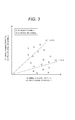
- FIG. 3 is a graph showing the correlation of the thermal conductivity of two rotor base materials.
- the lateral axis is set as the thermal conductivity T1 of the rotor base material 1
- the vertical axis is set as the thermal conductivity T2 of the rotor base material 2.
- a region is also shown in which the butting section of two rotor base materials could fuse by same heat input quantity in a preparatory test.
- the region is the area where the ratio of the thermal conductivity of two rotor base materials becomes 2/3 to 3/2.
- Table 1 shows the kind of the alloy and the composition range of the rotor base materials constituting the dissimilar material welded rotor.
- Rotor parent material C Mn Ni Cr Mo w Nb Co B V Ti Al Ta Hf Zr Fe Ni-based super alloy 0.05 ⁇ 0.20 bal. 13 ⁇ 15.5 0.1 ⁇ 2.0 4.5 ⁇ 10 0.1 ⁇ 1.0 5 ⁇ 15 0.001 ⁇ 0.03 0.1 ⁇ 2.0 4.0 ⁇ 5.5 0.1 ⁇ 3.0 0.1 ⁇ 2.0 0.01 ⁇ 0.1 Ni-Fe-based super alloy ⁇ 0.05 bal.
- the present example relates to an example employing the Ni-based super alloy and 12% Cr steel out of the rotor base materials shown in Table 1 and welding them.
- FIG. 4 shows the outline of a tungsten-inert gas welding machine used for welding a turbine rotor as an example.
- a welding machine 40 includes a drive unit 43, a welding unit 44, a torch 48 and a control unit 47, and a gas bombe 49 is connected via a gas hose 152. It is configured that inert gas of the gas bombe 49 is transferred to the torch 48 via a gas hose 151. Nitrogen, argon or the like is used as the inert gas.
- a signal cable 45 transmitting and receiving signals is arranged between the drive unit 43 and the control unit 47.
- a signal cable 46 transmitting and receiving signals is arranged between the welding unit 44 and the control unit 47.
- a turbine rotor 41 is arranged in a positioner 50 and is rotatable around the axis of the turbine rotor 41.
- the positioner 50 is connected to the control unit 47 via a signal cable 154 and is configured to be capable of rotating the turbine rotor 41 by the control unit 47.
- an earth cable 153 is connected to the turbine rotor 41, and the electric potential of the turbine rotor 41 is suppressed from varying in welding.
- the welding unit 44 is movable at least in the axial direction of the turbine rotor 41 by the drive unit 43, and is configured so as to execute welding while making the torch 48 approach the weld section 42 of the turbine rotor 41.
- the drive unit 43 shown in the present drawing is of a self standing type that moves while being tightly attached to a welding structure (turbine rotor 41), other types configured so that the drive unit 43 moves by an external force such as a scanning arm and the like for example are also applicable.
- the tungsten-inert gas welding with 20 kJ/cm heat input quantity was employed, however, other methods such as submerged arc welding (SAW), shielded metal arc welding (SMAW), metal inert gas welding (MIG welding), laser beam welding (LBW), CMT (cold metal transfer) may also be used for example.
- SAW submerged arc welding
- SMAW shielded metal arc welding
- MIG welding metal inert gas welding
- LW laser beam welding
- CMT cold metal transfer
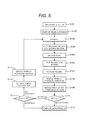
- FIG. 5 is a flowchart showing the welding step of the turbine rotor of the present example.
- one rotor base material is incorporated into another rotor base material (S101).
- start of the welding process is instructed (S102).
- the rotor base material is preheated (S103).
- an electric furnace, gas burner, high frequency induction heater and the like can be cited, however, other systems are also applicable.
- buttering buildup is executed with respect to one rotor base material using the welding unit shown in FIG. 4 (buttering buildup step S104). Thereafter, the buttering buildup and a part of two rotor base materials are subjected to groove work (groove work step S105). After the buttering buildup of one rotor base material and the other rotor base material are made butt against each other and are aligned to each other, penetration bead welding is executed by heating the butting section that is the contact section of the buttering buildup of one rotor base material and the other rotor base material from the outside of the rotor (penetration bead forming step S106).
- weld defect inspection for the weld section is executed (S109).
- the penetrant test (PT), visual test (VT), ultrasonic test (UT), radiographic test (RT), magnetic particle test (MT) and the like can be cited, however, other methods are also applicable.
- Presence/absence of the defect is determined (S110).
- whether the defect size is allowable or not from the aspect of the mechanical strength is determined (S111).
- the weld section is cut and removed (S112), the end surface of the rotor is subjected to groove work (S113), and the process returns to the preheating step (S103).
- FIG. 6 is a partial enlarged cross-sectional view continuously showing the welding step of FIG. 5 .
- the dotted line section 28 of FIG. 2B is enlarged, deformed into a flat plane shape, and is shown in (A) to (F).
- the present drawing shows the case two rotor base materials with different material on the high temperature side and the low temperature side are welded to each other.
- the buildup welding section 62 is directly applied to the surface of the rotor base material 61.
- the present example is characterized that the groove of the high temperature side rotor base material is subjected to buttering beforehand in order to eliminate the difference in the chemical composition, heat treatment condition and the like between the high temperature side rotor base material and the low temperature side rotor base material.
- description on the points identical to those of example 1 will be omitted, and only the points different from example 1 will be described.
- FIG. 7 is a flowchart showing the welding step of the turbine rotor of the present example.
- the steps added in the present example are S201 to S203 when compared to example 1.
- buttering step S201 the entire surface of the groove arranged in the high temperature side rotor base material beforehand is subjected to buttering, and an entire surface buttering section is arranged. The reason of doing so is for relaxing the difference in the chemical composition and heat treatment condition between the high temperature side rotor base material and the low temperature side rotor base material.
- heat treatment S203 is for securing the strength suitable to the high temperature side rotor base material, and is disadvantageous for the low temperature side rotor base material. Therefore, heat treatment S203 should be executed before the low temperature side rotor base material is welded to the high temperature side rotor base material.
- S103 and onward are similar to those of example 1.
- FIG. 8 is a continuous cross-sectional view showing the welding step of example 2.
- the point different from example 1 mainly is the step shown in (A).
- an entire surface buttering section 71 is formed in the high temperature side rotor base material 61 beforehand prior to applying a buildup welding section 72 (before (B)).
- the thickness in the axial direction of the entire surface buttering section 71 is 5 mm or more and 15 mm or less (5 to 15 mm).
- the thickness is thinner than 5 mm, there may be an effect of dilution of the deposited metal for regular welding.
- the thickness is thicker than 15 mm, the effect of dilution of the deposited metal for regular welding is eliminated, however increase of the execution time is concerned about.
- a groove 73 is formed in (C) of FIG. 8
- a gap 76 is formed by making the high temperature side rotor base material 61 and the low temperature side rotor base material 64 butt against each other in (D)
- a penetration bead 77 is formed in (E)
- the gap 76 is subjected to butt welding using a weld metal 78 in (F).
- FIG. 9 is a continuous cross-sectional view showing the welding step of example 3.
- a buildup welding section 72 is arranged in a part of the entire surface buttering section 71.
- a buildup welding section 91 is arranged in the low temperature side rotor base material 64 (B), and a groove 95 is formed (C).
- a gap 96 is formed by making the high temperature side rotor base material 61 and the low temperature side rotor base material 64 butt against each other (D), a penetration bead 97 is formed (E), and the gap 96 is subjected to butt welding using a weld metal 98 (F).
- the Ni-Fe-based super alloy and 12% Cr steel were employed out of the rotor base materials shown in Table 1. More specifically, the present example is different from example 1 only in the chemical composition of the rotor base material, and is same in the welding step and others.
- the thermal property of the rotor base material of an alloy whose main composition is Ni causes the problems similar to those of example 1 different from the rotor base material of the iron-based alloy material. Accordingly, the problems can be solved by a procedure same to that of example 1.
- the Ni-based super alloy and 1% Cr-Mo-V steel were employed out of the rotor base materials shown in Table 1. More specifically, the present example is different from example 1 only in the chemical composition of the rotor base material, and is same in the welding step and others.
- the thermal property of the rotor base material of an alloy whose main composition is Ni causes the problems similar to those of example 1 different from the rotor base material of the iron-based alloy material. Accordingly, the problems can be solved by a procedure same to that of example 1.
- the Ni-Fe-based super alloy and 1% Cr-Mo-V steel were employed out of the rotor base materials shown in Table 1. More specifically, the present example is different from example 1 only in the chemical composition of the rotor base material, and is same in the welding step and others.
- the thermal property of the rotor base material of an alloy whose main composition is Ni causes the problems similar to those of example 1 different from rotor base material of the iron-based alloy material. Accordingly, the problems can be solved by a procedure same to that of example 1.
Landscapes
- Engineering & Computer Science (AREA)
- Mechanical Engineering (AREA)
- Physics & Mathematics (AREA)
- Plasma & Fusion (AREA)
- General Engineering & Computer Science (AREA)
- Turbine Rotor Nozzle Sealing (AREA)
- Arc Welding In General (AREA)
- Butt Welding And Welding Of Specific Article (AREA)
- Laser Beam Processing (AREA)
Applications Claiming Priority (1)
| Application Number | Priority Date | Filing Date | Title |
|---|---|---|---|
| JP2012140472A JP5955125B2 (ja) | 2012-06-22 | 2012-06-22 | タービンロータ及びその製造方法及び当該タービンロータを用いた蒸気タービン |
Publications (3)
| Publication Number | Publication Date |
|---|---|
| EP2676759A2 true EP2676759A2 (de) | 2013-12-25 |
| EP2676759A3 EP2676759A3 (de) | 2016-11-23 |
| EP2676759B1 EP2676759B1 (de) | 2018-04-11 |
Family
ID=48782864
Family Applications (1)
| Application Number | Title | Priority Date | Filing Date |
|---|---|---|---|
| EP13172975.8A Not-in-force EP2676759B1 (de) | 2012-06-22 | 2013-06-20 | Turbinenrotor, herstellungsverfahren dafür und dampfturbine mit solchem turbinenrotor |
Country Status (4)
| Country | Link |
|---|---|
| US (1) | US9598962B2 (de) |
| EP (1) | EP2676759B1 (de) |
| JP (1) | JP5955125B2 (de) |
| CN (1) | CN103510996B (de) |
Families Citing this family (17)
| Publication number | Priority date | Publication date | Assignee | Title |
|---|---|---|---|---|
| US9546551B2 (en) * | 2013-09-17 | 2017-01-17 | General Electric Company | Repaired turbine rotor wheel dovetail and related method |
| DE112015000410T5 (de) * | 2014-01-15 | 2016-10-13 | Ihi Corporation | Verfahren zum Schweissen von Welle und Laufrad in Turbinenwelle, Turbinenwelle und Schweissvorrichtung |
| CN104084772B (zh) * | 2014-07-07 | 2016-08-24 | 焦作市双力机械有限公司 | 一种离心式脱水机转子体的制造工艺 |
| KR101716839B1 (ko) | 2014-12-24 | 2017-03-15 | 두산중공업 주식회사 | 로터의 가공 기준점 표시장치 및 그 표시방법 |
| US10500672B2 (en) * | 2015-02-04 | 2019-12-10 | Fisher Controls International Llc | Methods and apparatus for welding work pieces having dissimilar compositions |
| CN104842033A (zh) * | 2015-05-05 | 2015-08-19 | 柳州金茂机械有限公司 | 一种定子焊接工艺 |
| CN104842032A (zh) * | 2015-05-05 | 2015-08-19 | 柳州金茂机械有限公司 | 一种转子焊接工艺 |
| CN106282667B (zh) * | 2015-06-12 | 2018-05-08 | 中南大学 | 一种镍基高温合金及其制备方法 |
| CN109072347A (zh) * | 2016-04-20 | 2018-12-21 | 奥科宁克有限公司 | 铝、钴、铁和镍的fcc材料及由其制成的产物 |
| CN106239055A (zh) * | 2016-08-29 | 2016-12-21 | 东方电气集团东方锅炉股份有限公司 | 一种厚壁异种钢接头坡口的设计和加工方法 |
| CN106736300B (zh) * | 2017-01-10 | 2019-01-25 | 上海电气电站设备有限公司 | 由异种材料构成的涡轮转子的制造方法 |
| PL420172A1 (pl) * | 2017-01-12 | 2018-07-16 | Roboty Przemysłowe Spółka Z Ograniczoną Odpowiedzialnością | Sposób łączenia spawaniem wiązką lasera elementów konstrukcyjnych ze stali wysokowytrzymałej o gwarantowanej granicy plastyczności 1300 Mpa po obróbce cieplnej |
| CN108500559B (zh) * | 2017-02-24 | 2020-02-14 | 中国石油天然气集团公司 | 一种超大管径厚壁x80钢级螺旋埋弧焊管的制造方法 |
| JP6289713B1 (ja) * | 2017-06-12 | 2018-03-07 | 南海鋼材株式会社 | 溶接システム及び溶接方法 |
| JP2019105250A (ja) * | 2017-12-14 | 2019-06-27 | 株式会社東芝 | タービンロータおよびタービンロータの製造方法 |
| JP7325194B2 (ja) * | 2019-02-19 | 2023-08-14 | 三菱重工業株式会社 | 溶接物製造方法、溶接物製造システム及び溶接物 |
| CN115044818B (zh) * | 2022-07-25 | 2023-05-26 | 华能国际电力股份有限公司 | 一种650°c及以上等级汽轮机用转子及其制备方法 |
Family Cites Families (22)
| Publication number | Priority date | Publication date | Assignee | Title |
|---|---|---|---|---|
| GB1218927A (en) * | 1967-06-29 | 1971-01-13 | English Steel Corp Ltd | Improvements in heat-resisting alloy steels |
| US4962586A (en) * | 1989-11-29 | 1990-10-16 | Westinghouse Electric Corp. | Method of making a high temperature - low temperature rotor for turbines |
| JP3999402B2 (ja) | 1998-06-09 | 2007-10-31 | 三菱重工業株式会社 | 蒸気タービンの異材溶接ロータ |
| JP2000254774A (ja) | 1999-03-09 | 2000-09-19 | Ishikawajima Harima Heavy Ind Co Ltd | 異材溶接方法および水素改質装置の管路部材交換方法 |
| JP2000254776A (ja) | 1999-03-10 | 2000-09-19 | Toshiba Corp | 原子炉内部配管溶接部の応力腐食割れ防止方法 |
| US6454531B1 (en) * | 2000-12-27 | 2002-09-24 | General Electric Company | Fabricating turbine rotors composed of separate components |
| DE10112062A1 (de) | 2001-03-14 | 2002-09-19 | Alstom Switzerland Ltd | Verfahren zum Zusammenschweißen zweier thermisch unterschiedlich belasteter Teile sowie nach einem solchen Verfahren hergestellte Turbomaschine |
| US6962483B2 (en) * | 2003-06-18 | 2005-11-08 | General Electric Company | Multiple alloy rotor |
| US20080011812A1 (en) | 2005-11-04 | 2008-01-17 | General Electric Company | Integral backing ring for stub shaft weld repairs of rotating equipment and related method |
| CN101341001A (zh) | 2005-12-22 | 2009-01-07 | 阿尔斯托姆科技有限公司 | 通过堆焊和去应力退火制造低压蒸汽涡轮机的焊接的转子的方法 |
| JP2007278064A (ja) * | 2006-04-03 | 2007-10-25 | Hitachi Ltd | 蒸気タービン溶接ロータとその製造方法及び蒸気タービンとその発電プラント |
| JP4261562B2 (ja) * | 2006-08-25 | 2009-04-30 | 株式会社日立製作所 | 高温強度と高温延性の優れたNi−Fe基鍛造超合金とその製造法および蒸気タービンロータ |
| JP5003130B2 (ja) * | 2006-12-04 | 2012-08-15 | 株式会社日立製作所 | タービンロータ |
| JP5049578B2 (ja) * | 2006-12-15 | 2012-10-17 | 株式会社東芝 | 蒸気タービン |
| JP2008215181A (ja) * | 2007-03-05 | 2008-09-18 | Hitachi Ltd | タービンロータ |
| JP2009248095A (ja) | 2008-04-01 | 2009-10-29 | Toshiba Corp | Ni基溶接材料を用いた溶接方法 |
| JP2010031812A (ja) | 2008-07-31 | 2010-02-12 | Hitachi Ltd | タービンロータ |
| JP4959744B2 (ja) | 2009-03-31 | 2012-06-27 | 株式会社日立製作所 | 蒸気タービン用タービンロータ及び蒸気タービン |
| JP5193960B2 (ja) | 2009-06-30 | 2013-05-08 | 株式会社日立製作所 | タービンロータ |
| JP2012030237A (ja) | 2010-07-29 | 2012-02-16 | Hitachi-Ge Nuclear Energy Ltd | 構造部材の溶接継手構造及びその溶接方法 |
| JP2012061498A (ja) | 2010-09-16 | 2012-03-29 | Ihi Corp | Ni基超合金に対する鉄鋼材料の溶接方法及び溶接継手 |
| JP5522802B2 (ja) * | 2011-05-23 | 2014-06-18 | 株式会社日立製作所 | タービンロータ等の大型溶接構造物の異材溶接部材及びタービンロータ |
-
2012
- 2012-06-22 JP JP2012140472A patent/JP5955125B2/ja not_active Expired - Fee Related
-
2013
- 2013-06-20 EP EP13172975.8A patent/EP2676759B1/de not_active Not-in-force
- 2013-06-20 US US13/923,183 patent/US9598962B2/en not_active Expired - Fee Related
- 2013-06-21 CN CN201310250031.8A patent/CN103510996B/zh not_active Expired - Fee Related
Also Published As
| Publication number | Publication date |
|---|---|
| CN103510996B (zh) | 2015-11-18 |
| CN103510996A (zh) | 2014-01-15 |
| JP2014005754A (ja) | 2014-01-16 |
| US20130343899A1 (en) | 2013-12-26 |
| US9598962B2 (en) | 2017-03-21 |
| JP5955125B2 (ja) | 2016-07-20 |
| EP2676759A3 (de) | 2016-11-23 |
| EP2676759B1 (de) | 2018-04-11 |
Similar Documents
| Publication | Publication Date | Title |
|---|---|---|
| EP2676759B1 (de) | Turbinenrotor, herstellungsverfahren dafür und dampfturbine mit solchem turbinenrotor | |
| US11292078B2 (en) | System for and method of linking by friction welding a first piece of steel to a second piece of steel with use of Ni-based alloys adapter | |
| JP4828667B2 (ja) | 溶接構造体の突合せ溶接継手、及びその製造方法 | |
| EP1802417B1 (de) | Verfahren zum verlängern der lebensdauer von geschweissten legierungsstahlverbindungen durch beseitigen und verkleinern der wärmeeinflusszone | |
| EP2527073B1 (de) | Geschweisste Verbindung mit ungleicher Metallschweißung und Herstellungsverfahren großer geschweißter Strukturen wie zum Beispiel Turbinenrotoren | |
| JPH03237205A (ja) | タービンロータおよびそのタービンロータの形成方法 | |
| US20130121868A1 (en) | Method of manufacturing a weld-free apparatus for connection of dissimilar metals using functionally graded compositionally control powder metallurgy and hot isostatic processing methods | |
| Srinivasan et al. | Choice of welding consumable and procedure qualification for welding of 304HCu austenitic stainless steel boiler tubes for Indian Advanced Ultra Super Critical power plant | |
| US11738404B2 (en) | Method to eliminate dissimilar metal welds | |
| EP2614914B1 (de) | Brennstoffdüse und Verfahren zur Herstellung einer Brennstoffdüse | |
| KR20100101564A (ko) | 노에 사용되는 증가되는 내부면을 갖는 관과 제조방법 및 적용 | |
| CN108581139A (zh) | 一种石油天然气输送用双金属复合管道的焊接方法 | |
| US20110035924A1 (en) | Developments in or relating to drum rotors | |
| US20080078754A1 (en) | Method of welding aluminum alloy steels | |
| JP6471444B2 (ja) | 熱間鍛造用金型の製造方法 | |
| JP2014020328A (ja) | タービンロータの製造方法、タービンロータ、および、溶接方法 | |
| US9068462B2 (en) | Process of welding a turbine blade, a process of welding a non-uniform article, and a welded turbine blade | |
| JP6736941B2 (ja) | 鋼部材の溶接方法、及び溶接材料 | |
| Siefert et al. | Weldability of EPRI P87 | |
| Udoh et al. | Creep and Failure Behavior of Welded Joints Made of Alloy 617B | |
| Suzuki et al. | Structural component development of three-layer cylinders for superconducting generators, Part 2: Development of three-layer welding techniques to extend axial length and evaluation of the welds | |
| JP2014001686A (ja) | 蒸気タービンロータの製造方法、蒸気タービンロータ、および、溶接方法 | |
| WELDING | Upton, NY 11973-5000, USA | |
| JP2003154484A (ja) | 二重金属配管の補修方法 | |
| JPH0550334A (ja) | 高低圧一体ロータの製造法 |
Legal Events
| Date | Code | Title | Description |
|---|---|---|---|
| PUAI | Public reference made under article 153(3) epc to a published international application that has entered the european phase |
Free format text: ORIGINAL CODE: 0009012 |
|
| AK | Designated contracting states |
Kind code of ref document: A2 Designated state(s): AL AT BE BG CH CY CZ DE DK EE ES FI FR GB GR HR HU IE IS IT LI LT LU LV MC MK MT NL NO PL PT RO RS SE SI SK SM TR |
|
| AX | Request for extension of the european patent |
Extension state: BA ME |
|
| 17P | Request for examination filed |
Effective date: 20131119 |
|
| RBV | Designated contracting states (corrected) |
Designated state(s): AL AT BE BG CH CY CZ DE DK EE ES FI FR GB GR HR HU IE IS IT LI LT LU LV MC MK MT NL NO PL PT RO RS SE SI SK SM TR |
|
| RAP1 | Party data changed (applicant data changed or rights of an application transferred) |
Owner name: MITSUBISHI HITACHI POWER SYSTEMS, LTD. |
|
| RAP1 | Party data changed (applicant data changed or rights of an application transferred) |
Owner name: MITSUBISHI HITACHI POWER SYSTEMS, LTD. |
|
| PUAL | Search report despatched |
Free format text: ORIGINAL CODE: 0009013 |
|
| AK | Designated contracting states |
Kind code of ref document: A3 Designated state(s): AL AT BE BG CH CY CZ DE DK EE ES FI FR GB GR HR HU IE IS IT LI LT LU LV MC MK MT NL NO PL PT RO RS SE SI SK SM TR |
|
| AX | Request for extension of the european patent |
Extension state: BA ME |
|
| RIC1 | Information provided on ipc code assigned before grant |
Ipc: B23K 9/04 20060101AFI20161019BHEP Ipc: B23K 9/173 20060101ALI20161019BHEP Ipc: B23K 101/00 20060101ALN20161019BHEP Ipc: B23P 15/04 20060101ALI20161019BHEP Ipc: B23K 9/167 20060101ALI20161019BHEP Ipc: F01D 5/06 20060101ALI20161019BHEP Ipc: B23K 101/06 20060101ALN20161019BHEP Ipc: B23P 15/00 20060101ALI20161019BHEP |
|
| RIC1 | Information provided on ipc code assigned before grant |
Ipc: B23K 101/06 20060101ALN20171010BHEP Ipc: B23K 9/04 20060101AFI20171010BHEP Ipc: B23P 15/04 20060101ALI20171010BHEP Ipc: B23P 15/00 20060101ALI20171010BHEP Ipc: F01D 5/06 20060101ALI20171010BHEP Ipc: B23K 101/00 20060101ALN20171010BHEP Ipc: B23K 9/173 20060101ALI20171010BHEP Ipc: B23K 9/167 20060101ALI20171010BHEP |
|
| GRAP | Despatch of communication of intention to grant a patent |
Free format text: ORIGINAL CODE: EPIDOSNIGR1 |
|
| STAA | Information on the status of an ep patent application or granted ep patent |
Free format text: STATUS: GRANT OF PATENT IS INTENDED |
|
| RIC1 | Information provided on ipc code assigned before grant |
Ipc: B23P 15/00 20060101ALI20171023BHEP Ipc: F01D 5/06 20060101ALI20171023BHEP Ipc: B23P 15/04 20060101ALI20171023BHEP Ipc: B23K 9/04 20060101AFI20171023BHEP Ipc: B23K 101/06 20060101ALN20171023BHEP Ipc: B23K 9/173 20060101ALI20171023BHEP Ipc: B23K 101/00 20060101ALN20171023BHEP Ipc: B23K 9/167 20060101ALI20171023BHEP |
|
| RIC1 | Information provided on ipc code assigned before grant |
Ipc: F01D 5/06 20060101ALI20171106BHEP Ipc: B23K 9/04 20060101AFI20171106BHEP Ipc: B23K 9/173 20060101ALI20171106BHEP Ipc: B23P 15/00 20060101ALI20171106BHEP Ipc: B23K 9/167 20060101ALI20171106BHEP Ipc: B23K 101/00 20060101ALN20171106BHEP Ipc: B23P 15/04 20060101ALI20171106BHEP Ipc: B23K 101/06 20060101ALN20171106BHEP |
|
| INTG | Intention to grant announced |
Effective date: 20171120 |
|
| GRAS | Grant fee paid |
Free format text: ORIGINAL CODE: EPIDOSNIGR3 |
|
| GRAA | (expected) grant |
Free format text: ORIGINAL CODE: 0009210 |
|
| STAA | Information on the status of an ep patent application or granted ep patent |
Free format text: STATUS: THE PATENT HAS BEEN GRANTED |
|
| AK | Designated contracting states |
Kind code of ref document: B1 Designated state(s): AL AT BE BG CH CY CZ DE DK EE ES FI FR GB GR HR HU IE IS IT LI LT LU LV MC MK MT NL NO PL PT RO RS SE SI SK SM TR |
|
| REG | Reference to a national code |
Ref country code: GB Ref legal event code: FG4D |
|
| REG | Reference to a national code |
Ref country code: CH Ref legal event code: EP |
|
| REG | Reference to a national code |
Ref country code: AT Ref legal event code: REF Ref document number: 987468 Country of ref document: AT Kind code of ref document: T Effective date: 20180415 |
|
| REG | Reference to a national code |
Ref country code: IE Ref legal event code: FG4D |
|
| REG | Reference to a national code |
Ref country code: DE Ref legal event code: R096 Ref document number: 602013035632 Country of ref document: DE |
|
| REG | Reference to a national code |
Ref country code: NL Ref legal event code: MP Effective date: 20180411 |
|
| REG | Reference to a national code |
Ref country code: LT Ref legal event code: MG4D |
|
| PG25 | Lapsed in a contracting state [announced via postgrant information from national office to epo] |
Ref country code: NL Free format text: LAPSE BECAUSE OF FAILURE TO SUBMIT A TRANSLATION OF THE DESCRIPTION OR TO PAY THE FEE WITHIN THE PRESCRIBED TIME-LIMIT Effective date: 20180411 |
|
| PG25 | Lapsed in a contracting state [announced via postgrant information from national office to epo] |
Ref country code: AL Free format text: LAPSE BECAUSE OF FAILURE TO SUBMIT A TRANSLATION OF THE DESCRIPTION OR TO PAY THE FEE WITHIN THE PRESCRIBED TIME-LIMIT Effective date: 20180411 Ref country code: ES Free format text: LAPSE BECAUSE OF FAILURE TO SUBMIT A TRANSLATION OF THE DESCRIPTION OR TO PAY THE FEE WITHIN THE PRESCRIBED TIME-LIMIT Effective date: 20180411 Ref country code: FI Free format text: LAPSE BECAUSE OF FAILURE TO SUBMIT A TRANSLATION OF THE DESCRIPTION OR TO PAY THE FEE WITHIN THE PRESCRIBED TIME-LIMIT Effective date: 20180411 Ref country code: NO Free format text: LAPSE BECAUSE OF FAILURE TO SUBMIT A TRANSLATION OF THE DESCRIPTION OR TO PAY THE FEE WITHIN THE PRESCRIBED TIME-LIMIT Effective date: 20180711 Ref country code: BG Free format text: LAPSE BECAUSE OF FAILURE TO SUBMIT A TRANSLATION OF THE DESCRIPTION OR TO PAY THE FEE WITHIN THE PRESCRIBED TIME-LIMIT Effective date: 20180711 Ref country code: LT Free format text: LAPSE BECAUSE OF FAILURE TO SUBMIT A TRANSLATION OF THE DESCRIPTION OR TO PAY THE FEE WITHIN THE PRESCRIBED TIME-LIMIT Effective date: 20180411 Ref country code: PL Free format text: LAPSE BECAUSE OF FAILURE TO SUBMIT A TRANSLATION OF THE DESCRIPTION OR TO PAY THE FEE WITHIN THE PRESCRIBED TIME-LIMIT Effective date: 20180411 Ref country code: SE Free format text: LAPSE BECAUSE OF FAILURE TO SUBMIT A TRANSLATION OF THE DESCRIPTION OR TO PAY THE FEE WITHIN THE PRESCRIBED TIME-LIMIT Effective date: 20180411 |
|
| PGFP | Annual fee paid to national office [announced via postgrant information from national office to epo] |
Ref country code: DE Payment date: 20180808 Year of fee payment: 6 |
|
| PG25 | Lapsed in a contracting state [announced via postgrant information from national office to epo] |
Ref country code: HR Free format text: LAPSE BECAUSE OF FAILURE TO SUBMIT A TRANSLATION OF THE DESCRIPTION OR TO PAY THE FEE WITHIN THE PRESCRIBED TIME-LIMIT Effective date: 20180411 Ref country code: GR Free format text: LAPSE BECAUSE OF FAILURE TO SUBMIT A TRANSLATION OF THE DESCRIPTION OR TO PAY THE FEE WITHIN THE PRESCRIBED TIME-LIMIT Effective date: 20180712 Ref country code: LV Free format text: LAPSE BECAUSE OF FAILURE TO SUBMIT A TRANSLATION OF THE DESCRIPTION OR TO PAY THE FEE WITHIN THE PRESCRIBED TIME-LIMIT Effective date: 20180411 Ref country code: RS Free format text: LAPSE BECAUSE OF FAILURE TO SUBMIT A TRANSLATION OF THE DESCRIPTION OR TO PAY THE FEE WITHIN THE PRESCRIBED TIME-LIMIT Effective date: 20180411 |
|
| REG | Reference to a national code |
Ref country code: AT Ref legal event code: MK05 Ref document number: 987468 Country of ref document: AT Kind code of ref document: T Effective date: 20180411 |
|
| PG25 | Lapsed in a contracting state [announced via postgrant information from national office to epo] |
Ref country code: PT Free format text: LAPSE BECAUSE OF FAILURE TO SUBMIT A TRANSLATION OF THE DESCRIPTION OR TO PAY THE FEE WITHIN THE PRESCRIBED TIME-LIMIT Effective date: 20180813 |
|
| REG | Reference to a national code |
Ref country code: DE Ref legal event code: R097 Ref document number: 602013035632 Country of ref document: DE |
|
| PG25 | Lapsed in a contracting state [announced via postgrant information from national office to epo] |
Ref country code: CZ Free format text: LAPSE BECAUSE OF FAILURE TO SUBMIT A TRANSLATION OF THE DESCRIPTION OR TO PAY THE FEE WITHIN THE PRESCRIBED TIME-LIMIT Effective date: 20180411 Ref country code: RO Free format text: LAPSE BECAUSE OF FAILURE TO SUBMIT A TRANSLATION OF THE DESCRIPTION OR TO PAY THE FEE WITHIN THE PRESCRIBED TIME-LIMIT Effective date: 20180411 Ref country code: SK Free format text: LAPSE BECAUSE OF FAILURE TO SUBMIT A TRANSLATION OF THE DESCRIPTION OR TO PAY THE FEE WITHIN THE PRESCRIBED TIME-LIMIT Effective date: 20180411 Ref country code: EE Free format text: LAPSE BECAUSE OF FAILURE TO SUBMIT A TRANSLATION OF THE DESCRIPTION OR TO PAY THE FEE WITHIN THE PRESCRIBED TIME-LIMIT Effective date: 20180411 Ref country code: AT Free format text: LAPSE BECAUSE OF FAILURE TO SUBMIT A TRANSLATION OF THE DESCRIPTION OR TO PAY THE FEE WITHIN THE PRESCRIBED TIME-LIMIT Effective date: 20180411 Ref country code: DK Free format text: LAPSE BECAUSE OF FAILURE TO SUBMIT A TRANSLATION OF THE DESCRIPTION OR TO PAY THE FEE WITHIN THE PRESCRIBED TIME-LIMIT Effective date: 20180411 |
|
| REG | Reference to a national code |
Ref country code: CH Ref legal event code: PL |
|
| PLBE | No opposition filed within time limit |
Free format text: ORIGINAL CODE: 0009261 |
|
| STAA | Information on the status of an ep patent application or granted ep patent |
Free format text: STATUS: NO OPPOSITION FILED WITHIN TIME LIMIT |
|
| PG25 | Lapsed in a contracting state [announced via postgrant information from national office to epo] |
Ref country code: IT Free format text: LAPSE BECAUSE OF FAILURE TO SUBMIT A TRANSLATION OF THE DESCRIPTION OR TO PAY THE FEE WITHIN THE PRESCRIBED TIME-LIMIT Effective date: 20180411 Ref country code: SM Free format text: LAPSE BECAUSE OF FAILURE TO SUBMIT A TRANSLATION OF THE DESCRIPTION OR TO PAY THE FEE WITHIN THE PRESCRIBED TIME-LIMIT Effective date: 20180411 |
|
| REG | Reference to a national code |
Ref country code: BE Ref legal event code: MM Effective date: 20180630 |
|
| 26N | No opposition filed |
Effective date: 20190114 |
|
| REG | Reference to a national code |
Ref country code: IE Ref legal event code: MM4A |
|
| GBPC | Gb: european patent ceased through non-payment of renewal fee |
Effective date: 20180711 |
|
| PG25 | Lapsed in a contracting state [announced via postgrant information from national office to epo] |
Ref country code: MC Free format text: LAPSE BECAUSE OF FAILURE TO SUBMIT A TRANSLATION OF THE DESCRIPTION OR TO PAY THE FEE WITHIN THE PRESCRIBED TIME-LIMIT Effective date: 20180411 Ref country code: LU Free format text: LAPSE BECAUSE OF NON-PAYMENT OF DUE FEES Effective date: 20180620 |
|
| PG25 | Lapsed in a contracting state [announced via postgrant information from national office to epo] |
Ref country code: CH Free format text: LAPSE BECAUSE OF NON-PAYMENT OF DUE FEES Effective date: 20180630 Ref country code: FR Free format text: LAPSE BECAUSE OF NON-PAYMENT OF DUE FEES Effective date: 20180630 Ref country code: LI Free format text: LAPSE BECAUSE OF NON-PAYMENT OF DUE FEES Effective date: 20180630 Ref country code: GB Free format text: LAPSE BECAUSE OF NON-PAYMENT OF DUE FEES Effective date: 20180711 Ref country code: IE Free format text: LAPSE BECAUSE OF NON-PAYMENT OF DUE FEES Effective date: 20180620 |
|
| PG25 | Lapsed in a contracting state [announced via postgrant information from national office to epo] |
Ref country code: SI Free format text: LAPSE BECAUSE OF FAILURE TO SUBMIT A TRANSLATION OF THE DESCRIPTION OR TO PAY THE FEE WITHIN THE PRESCRIBED TIME-LIMIT Effective date: 20180411 Ref country code: BE Free format text: LAPSE BECAUSE OF NON-PAYMENT OF DUE FEES Effective date: 20180630 |
|
| REG | Reference to a national code |
Ref country code: DE Ref legal event code: R119 Ref document number: 602013035632 Country of ref document: DE |
|
| PG25 | Lapsed in a contracting state [announced via postgrant information from national office to epo] |
Ref country code: MT Free format text: LAPSE BECAUSE OF NON-PAYMENT OF DUE FEES Effective date: 20180620 |
|
| PG25 | Lapsed in a contracting state [announced via postgrant information from national office to epo] |
Ref country code: TR Free format text: LAPSE BECAUSE OF FAILURE TO SUBMIT A TRANSLATION OF THE DESCRIPTION OR TO PAY THE FEE WITHIN THE PRESCRIBED TIME-LIMIT Effective date: 20180411 |
|
| PG25 | Lapsed in a contracting state [announced via postgrant information from national office to epo] |
Ref country code: DE Free format text: LAPSE BECAUSE OF NON-PAYMENT OF DUE FEES Effective date: 20200101 |
|
| PG25 | Lapsed in a contracting state [announced via postgrant information from national office to epo] |
Ref country code: HU Free format text: LAPSE BECAUSE OF FAILURE TO SUBMIT A TRANSLATION OF THE DESCRIPTION OR TO PAY THE FEE WITHIN THE PRESCRIBED TIME-LIMIT; INVALID AB INITIO Effective date: 20130620 |
|
| PG25 | Lapsed in a contracting state [announced via postgrant information from national office to epo] |
Ref country code: MK Free format text: LAPSE BECAUSE OF NON-PAYMENT OF DUE FEES Effective date: 20180411 Ref country code: CY Free format text: LAPSE BECAUSE OF FAILURE TO SUBMIT A TRANSLATION OF THE DESCRIPTION OR TO PAY THE FEE WITHIN THE PRESCRIBED TIME-LIMIT Effective date: 20180411 |
|
| PG25 | Lapsed in a contracting state [announced via postgrant information from national office to epo] |
Ref country code: IS Free format text: LAPSE BECAUSE OF FAILURE TO SUBMIT A TRANSLATION OF THE DESCRIPTION OR TO PAY THE FEE WITHIN THE PRESCRIBED TIME-LIMIT Effective date: 20180811 |