EP2664729A2 - Agencement comprenant des composants plats - Google Patents
Agencement comprenant des composants plats Download PDFInfo
- Publication number
- EP2664729A2 EP2664729A2 EP13450016.4A EP13450016A EP2664729A2 EP 2664729 A2 EP2664729 A2 EP 2664729A2 EP 13450016 A EP13450016 A EP 13450016A EP 2664729 A2 EP2664729 A2 EP 2664729A2
- Authority
- EP
- European Patent Office
- Prior art keywords
- locking
- substructure
- components
- support rails
- rails
- Prior art date
- Legal status (The legal status is an assumption and is not a legal conclusion. Google has not performed a legal analysis and makes no representation as to the accuracy of the status listed.)
- Withdrawn
Links
- 210000002105 tongue Anatomy 0.000 claims description 12
- 230000001419 dependent effect Effects 0.000 description 1
- 238000006073 displacement reaction Methods 0.000 description 1
Images


Classifications
-
- E—FIXED CONSTRUCTIONS
- E04—BUILDING
- E04F—FINISHING WORK ON BUILDINGS, e.g. STAIRS, FLOORS
- E04F13/00—Coverings or linings, e.g. for walls or ceilings
- E04F13/07—Coverings or linings, e.g. for walls or ceilings composed of covering or lining elements; Sub-structures therefor; Fastening means therefor
- E04F13/08—Coverings or linings, e.g. for walls or ceilings composed of covering or lining elements; Sub-structures therefor; Fastening means therefor composed of a plurality of similar covering or lining elements
- E04F13/0801—Separate fastening elements
- E04F13/0803—Separate fastening elements with load-supporting elongated furring elements between wall and covering elements
- E04F13/081—Separate fastening elements with load-supporting elongated furring elements between wall and covering elements with additional fastening elements between furring elements and covering elements
- E04F13/083—Hooking means on the back side of the covering elements
-
- F—MECHANICAL ENGINEERING; LIGHTING; HEATING; WEAPONS; BLASTING
- F16—ENGINEERING ELEMENTS AND UNITS; GENERAL MEASURES FOR PRODUCING AND MAINTAINING EFFECTIVE FUNCTIONING OF MACHINES OR INSTALLATIONS; THERMAL INSULATION IN GENERAL
- F16B—DEVICES FOR FASTENING OR SECURING CONSTRUCTIONAL ELEMENTS OR MACHINE PARTS TOGETHER, e.g. NAILS, BOLTS, CIRCLIPS, CLAMPS, CLIPS OR WEDGES; JOINTS OR JOINTING
- F16B5/00—Joining sheets or plates, e.g. panels, to one another or to strips or bars parallel to them
- F16B5/0004—Joining sheets, plates or panels in abutting relationship
- F16B5/0084—Joining sheets, plates or panels in abutting relationship characterised by particular locking means
- F16B5/0092—Joining sheets, plates or panels in abutting relationship characterised by particular locking means with locking means rotating about an axis parallel to the main plane and perpendicular to the abutting edge, e.g. screw, bayonet
Definitions
- the invention relates to an arrangement with the features of the introductory part of claim 1.
- the invention is based on the object to provide an arrangement of the type mentioned, which allow the simple fixing plate-shaped components to a support, for example on a frame, a wall or other supporting structural part.
- a substructure which can be attached to any support, e.g. a structural part, can be fixed and the plate-shaped components are releasably secured to the substructure, there is a great deal of flexibility and the ability to arrange the plate-shaped components on the substructure of the arrangement of any arrangement and also to remove or replace individual components.
- the locking of the tongues of the plate-shaped components in receiving openings of the substructure can be done by means of locking strips, which at least partially close the receiving openings in the substructure, in which engage the tongues.
- these locking strips by means of levers (“locking lever”) sliding strips that on, the receiving openings having retaining rails of the substructure are performed.
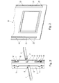
- An arrangement 1 according to the invention has in its substructure 2 at least two, but in particular more than two, retaining rails 3 fastened to any support, eg a building part, in a vertical and essentially vertical orientation.
- the lateral distance of the support member to be fastened to the building part 3 is defined by cross struts 4, which are inserted into holes 5 in the legs 6 of the support rails 3 and which are inserted with downwardly open slots 7 on the lower edge of these holes 5 so that the lateral spacing of the support rails 3 is defined by the transverse struts 4, namely the spacing of the slots 7 in a transverse strut 4.
- locking strips 10 are slidably guided, which, as in Fig. 2 . 4 and 5 shown, locking lugs 12 wear, which are assigned to the front, ie away from the web of the support rails 3, open recesses 11 ("receiving openings") in the legs 5 of the support rails 3.
- slots 17 are provided in the locking strips, which are aligned in the longitudinal direction and in the guide pins 18 which are provided on the inside of the legs 6 of the support rails 3, intervene.
- the locking strips 10 have on one side (away from the web of the support rails 3) open recesses into which from one side the locking lugs 12, which are aligned substantially in the longitudinal direction of the locking strips 10, protrude (see. Fig. 4 )
- the recesses 11 in the legs 6 of the support rails 3 at least partially close, are pivotable, angled locking lever 13 is provided.
- the locking lever 13 are pivotally mounted on the locking strips 10 about bearing 14 and engage with a jaw 15 via a provided on the legs 6 of the support rails 3 pin 16. By pressing (pivoting, see. 4 and 5 ) of the locking lever 13, the locking bar 10 relative to the support rails 3 for locking or unlocking the recesses 11 to be moved.
- the components 20 to be fastened to the substructure of the arrangement for example an in Fig. 3 partially shown video panel, has on its substructure 1, comprising support rails 3, cross braces 4, locking strips 10 and locking lever 13, facing side rails 21, of which tongues 22 protrude.
- the tongues 22 are inserted when attaching the component 20 to the substructure 2 in the recesses 11 in the legs 6 of the support rails 3 and then fixed by pressing the locking lever 13 effected displacement of the locking bar 10 in the recesses 11 of the support rails 3 ("locked") like this in Fig. 4 and 7 is shown.
- a single component 20 of the inventive arrangement 1 is to be removed from the substructure 2, it is possible to detect the locking lever 13 on its actuating part 24 by means of a narrow (flat) hook-like tool, by the tool between the, spaced apart components 20 is introduced and the locking lever 13 from the in Fig. 4 shown position in the in Fig. 5 shown position is pivoted so that the affected component 20 'can be removed in the embodiment of the video panel of the substructure 2, because the tongue 22 after the locking lug 12 has been withdrawn, is unlocked.
Landscapes
- Engineering & Computer Science (AREA)
- Architecture (AREA)
- Civil Engineering (AREA)
- Structural Engineering (AREA)
- Mirrors, Picture Frames, Photograph Stands, And Related Fastening Devices (AREA)
Applications Claiming Priority (1)
| Application Number | Priority Date | Filing Date | Title |
|---|---|---|---|
| AT5802012A AT512295B1 (de) | 2012-05-15 | 2012-05-15 | Anordnung mit flächigen Bauteilen |
Publications (1)
| Publication Number | Publication Date |
|---|---|
| EP2664729A2 true EP2664729A2 (fr) | 2013-11-20 |
Family
ID=48190893
Family Applications (1)
| Application Number | Title | Priority Date | Filing Date |
|---|---|---|---|
| EP13450016.4A Withdrawn EP2664729A2 (fr) | 2012-05-15 | 2013-04-22 | Agencement comprenant des composants plats |
Country Status (2)
| Country | Link |
|---|---|
| EP (1) | EP2664729A2 (fr) |
| AT (1) | AT512295B1 (fr) |
Cited By (1)
| Publication number | Priority date | Publication date | Assignee | Title |
|---|---|---|---|---|
| CN104949156A (zh) * | 2015-06-29 | 2015-09-30 | 王明 | 一种炉灶 |
Families Citing this family (1)
| Publication number | Priority date | Publication date | Assignee | Title |
|---|---|---|---|---|
| JP5647720B1 (ja) * | 2013-10-01 | 2015-01-07 | 菊川工業株式会社 | 壁パネル固定構造 |
Family Cites Families (3)
| Publication number | Priority date | Publication date | Assignee | Title |
|---|---|---|---|---|
| DE2355568A1 (de) * | 1973-11-07 | 1975-05-22 | Boegle Kg Wilhelm | Halteriegel zum loesbaren befestigen von platten an traegerschienen |
| DE29814948U1 (de) * | 1998-08-20 | 1998-12-17 | Wendker Gmbh & Co Kg | Befestigungssystem für Wandelemente an Gebäudewänden |
| CA2685707A1 (fr) * | 2008-11-10 | 2010-05-10 | Groupe Artitalia Inc. | Ensemble de paroi muni de tablettes |
-
2012
- 2012-05-15 AT AT5802012A patent/AT512295B1/de not_active IP Right Cessation
-
2013
- 2013-04-22 EP EP13450016.4A patent/EP2664729A2/fr not_active Withdrawn
Cited By (1)
| Publication number | Priority date | Publication date | Assignee | Title |
|---|---|---|---|---|
| CN104949156A (zh) * | 2015-06-29 | 2015-09-30 | 王明 | 一种炉灶 |
Also Published As
| Publication number | Publication date |
|---|---|
| AT512295B1 (de) | 2013-07-15 |
| AT512295A4 (de) | 2013-07-15 |
Similar Documents
| Publication | Publication Date | Title |
|---|---|---|
| DE4436166C2 (de) | Untergestell für Tischplatten für Einzel- und Reihentische | |
| EP3496571B1 (fr) | Châssis destiné à un tiroir | |
| DE102009048894A1 (de) | System zur Befestigung eines Sitzes, insbesondere eines Luftfahrzeugs, und ein solches System aufweisender Sitz | |
| EP2389836B1 (fr) | Rayonnage | |
| EP0968342A1 (fr) | Echaffaudage a montants verticaux et diagonaux | |
| AT512295B1 (de) | Anordnung mit flächigen Bauteilen | |
| EP3504947A1 (fr) | Dispositif d'aide au montage | |
| DE102008001972A1 (de) | Befestigungselement für eine Rollenleiste und Durchlaufregal | |
| DE10044969B4 (de) | Wandprofilleiste | |
| DE2828192A1 (de) | Skitraeger mit sicherheitsverschluss | |
| DE202005002424U1 (de) | Ausstellungs- oder Verkaufsständer | |
| DE202015003114U1 (de) | Sicherungssystem für Dachziegel | |
| DE202013000152U1 (de) | Gitterboden und Käfiganlage für Geflügel | |
| DE60319315T2 (de) | Verriegelungselement für einen Gitterrost auf einer Entwässerungsrinne und Werkzeug zum Entfernen desselben | |
| DE202012009700U1 (de) | Dachhaken | |
| DE202012101903U1 (de) | Nachtschrank mit abnehmbarem Betttisch | |
| EP2462840B1 (fr) | Siège à suspension | |
| DE202008000021U1 (de) | Stützbock für eine Arbeitsplattform sowie Arbeitsplattform | |
| DE202016003333U1 (de) | Befestigungssystem | |
| DE102004002509B4 (de) | Regalsystem | |
| DE102015000206A1 (de) | Befestigungsvorrichtung für Absperrholme an Pfosten von Absperreinrichtungen | |
| DE102012107524A1 (de) | Einrichtung zur Präsentation und/oder Aufnahme von Gegenständen | |
| DE102017008020A1 (de) | Modulare Wand | |
| DE102009001275A1 (de) | Regalsystem | |
| AT3299U1 (de) | Warengestell mit höhenverstellbarem fachboden |
Legal Events
| Date | Code | Title | Description |
|---|---|---|---|
| PUAI | Public reference made under article 153(3) epc to a published international application that has entered the european phase |
Free format text: ORIGINAL CODE: 0009012 |
|
| AK | Designated contracting states |
Kind code of ref document: A2 Designated state(s): AL AT BE BG CH CY CZ DE DK EE ES FI FR GB GR HR HU IE IS IT LI LT LU LV MC MK MT NL NO PL PT RO RS SE SI SK SM TR |
|
| AX | Request for extension of the european patent |
Extension state: BA ME |
|
| STAA | Information on the status of an ep patent application or granted ep patent |
Free format text: STATUS: THE APPLICATION IS DEEMED TO BE WITHDRAWN |
|
| 18D | Application deemed to be withdrawn |
Effective date: 20161101 |