EP2660184B1 - Système de production d'électricité à régénération d'énergie applicable à un véhicule pour le chargement, le déchargement et le transport - Google Patents
Système de production d'électricité à régénération d'énergie applicable à un véhicule pour le chargement, le déchargement et le transport Download PDFInfo
- Publication number
- EP2660184B1 EP2660184B1 EP11853792.7A EP11853792A EP2660184B1 EP 2660184 B1 EP2660184 B1 EP 2660184B1 EP 11853792 A EP11853792 A EP 11853792A EP 2660184 B1 EP2660184 B1 EP 2660184B1
- Authority
- EP
- European Patent Office
- Prior art keywords
- port
- valve
- switch
- branch
- directional valve
- Prior art date
- Legal status (The legal status is an assumption and is not a legal conclusion. Google has not performed a legal analysis and makes no representation as to the accuracy of the status listed.)
- Active
Links
- 238000010248 power generation Methods 0.000 title 1
- 230000008929 regeneration Effects 0.000 title 1
- 238000011069 regeneration method Methods 0.000 title 1
- 238000001514 detection method Methods 0.000 claims description 28
- 238000011084 recovery Methods 0.000 claims description 17
- 230000011664 signaling Effects 0.000 claims description 16
- 238000013016 damping Methods 0.000 claims description 10
- 238000004146 energy storage Methods 0.000 claims description 4
- 230000006870 function Effects 0.000 description 17
- 238000000034 method Methods 0.000 description 12
- 230000008569 process Effects 0.000 description 12
- 238000005381 potential energy Methods 0.000 description 5
- 230000001360 synchronised effect Effects 0.000 description 5
- 238000006243 chemical reaction Methods 0.000 description 3
- WHXSMMKQMYFTQS-UHFFFAOYSA-N Lithium Chemical compound [Li] WHXSMMKQMYFTQS-UHFFFAOYSA-N 0.000 description 2
- 239000003990 capacitor Substances 0.000 description 2
- 238000010438 heat treatment Methods 0.000 description 2
- 229910052744 lithium Inorganic materials 0.000 description 2
- 230000009471 action Effects 0.000 description 1
- 230000002411 adverse Effects 0.000 description 1
- 230000005611 electricity Effects 0.000 description 1
- 230000004048 modification Effects 0.000 description 1
- 238000012986 modification Methods 0.000 description 1
- 230000007659 motor function Effects 0.000 description 1
- 230000002035 prolonged effect Effects 0.000 description 1
Images


Classifications
-
- F—MECHANICAL ENGINEERING; LIGHTING; HEATING; WEAPONS; BLASTING
- F15—FLUID-PRESSURE ACTUATORS; HYDRAULICS OR PNEUMATICS IN GENERAL
- F15B—SYSTEMS ACTING BY MEANS OF FLUIDS IN GENERAL; FLUID-PRESSURE ACTUATORS, e.g. SERVOMOTORS; DETAILS OF FLUID-PRESSURE SYSTEMS, NOT OTHERWISE PROVIDED FOR
- F15B15/00—Fluid-actuated devices for displacing a member from one position to another; Gearing associated therewith
-
- B—PERFORMING OPERATIONS; TRANSPORTING
- B66—HOISTING; LIFTING; HAULING
- B66F—HOISTING, LIFTING, HAULING OR PUSHING, NOT OTHERWISE PROVIDED FOR, e.g. DEVICES WHICH APPLY A LIFTING OR PUSHING FORCE DIRECTLY TO THE SURFACE OF A LOAD
- B66F9/00—Devices for lifting or lowering bulky or heavy goods for loading or unloading purposes
- B66F9/06—Devices for lifting or lowering bulky or heavy goods for loading or unloading purposes movable, with their loads, on wheels or the like, e.g. fork-lift trucks
- B66F9/075—Constructional features or details
- B66F9/20—Means for actuating or controlling masts, platforms, or forks
- B66F9/22—Hydraulic devices or systems
-
- F—MECHANICAL ENGINEERING; LIGHTING; HEATING; WEAPONS; BLASTING
- F15—FLUID-PRESSURE ACTUATORS; HYDRAULICS OR PNEUMATICS IN GENERAL
- F15B—SYSTEMS ACTING BY MEANS OF FLUIDS IN GENERAL; FLUID-PRESSURE ACTUATORS, e.g. SERVOMOTORS; DETAILS OF FLUID-PRESSURE SYSTEMS, NOT OTHERWISE PROVIDED FOR
- F15B21/00—Common features of fluid actuator systems; Fluid-pressure actuator systems or details thereof, not covered by any other group of this subclass
- F15B21/14—Energy-recuperation means
-
- F—MECHANICAL ENGINEERING; LIGHTING; HEATING; WEAPONS; BLASTING
- F15—FLUID-PRESSURE ACTUATORS; HYDRAULICS OR PNEUMATICS IN GENERAL
- F15B—SYSTEMS ACTING BY MEANS OF FLUIDS IN GENERAL; FLUID-PRESSURE ACTUATORS, e.g. SERVOMOTORS; DETAILS OF FLUID-PRESSURE SYSTEMS, NOT OTHERWISE PROVIDED FOR
- F15B2211/00—Circuits for servomotor systems
- F15B2211/20—Fluid pressure source, e.g. accumulator or variable axial piston pump
- F15B2211/205—Systems with pumps
- F15B2211/2053—Type of pump
- F15B2211/20569—Type of pump capable of working as pump and motor
-
- F—MECHANICAL ENGINEERING; LIGHTING; HEATING; WEAPONS; BLASTING
- F15—FLUID-PRESSURE ACTUATORS; HYDRAULICS OR PNEUMATICS IN GENERAL
- F15B—SYSTEMS ACTING BY MEANS OF FLUIDS IN GENERAL; FLUID-PRESSURE ACTUATORS, e.g. SERVOMOTORS; DETAILS OF FLUID-PRESSURE SYSTEMS, NOT OTHERWISE PROVIDED FOR
- F15B2211/00—Circuits for servomotor systems
- F15B2211/30—Directional control
- F15B2211/31—Directional control characterised by the positions of the valve element
- F15B2211/3105—Neutral or centre positions
- F15B2211/3116—Neutral or centre positions the pump port being open in the centre position, e.g. so-called open centre
-
- F—MECHANICAL ENGINEERING; LIGHTING; HEATING; WEAPONS; BLASTING
- F15—FLUID-PRESSURE ACTUATORS; HYDRAULICS OR PNEUMATICS IN GENERAL
- F15B—SYSTEMS ACTING BY MEANS OF FLUIDS IN GENERAL; FLUID-PRESSURE ACTUATORS, e.g. SERVOMOTORS; DETAILS OF FLUID-PRESSURE SYSTEMS, NOT OTHERWISE PROVIDED FOR
- F15B2211/00—Circuits for servomotor systems
- F15B2211/60—Circuit components or control therefor
- F15B2211/615—Filtering means
-
- F—MECHANICAL ENGINEERING; LIGHTING; HEATING; WEAPONS; BLASTING
- F15—FLUID-PRESSURE ACTUATORS; HYDRAULICS OR PNEUMATICS IN GENERAL
- F15B—SYSTEMS ACTING BY MEANS OF FLUIDS IN GENERAL; FLUID-PRESSURE ACTUATORS, e.g. SERVOMOTORS; DETAILS OF FLUID-PRESSURE SYSTEMS, NOT OTHERWISE PROVIDED FOR
- F15B2211/00—Circuits for servomotor systems
- F15B2211/60—Circuit components or control therefor
- F15B2211/63—Electronic controllers
- F15B2211/6303—Electronic controllers using input signals
- F15B2211/6306—Electronic controllers using input signals representing a pressure
- F15B2211/6313—Electronic controllers using input signals representing a pressure the pressure being a load pressure
-
- F—MECHANICAL ENGINEERING; LIGHTING; HEATING; WEAPONS; BLASTING
- F15—FLUID-PRESSURE ACTUATORS; HYDRAULICS OR PNEUMATICS IN GENERAL
- F15B—SYSTEMS ACTING BY MEANS OF FLUIDS IN GENERAL; FLUID-PRESSURE ACTUATORS, e.g. SERVOMOTORS; DETAILS OF FLUID-PRESSURE SYSTEMS, NOT OTHERWISE PROVIDED FOR
- F15B2211/00—Circuits for servomotor systems
- F15B2211/80—Other types of control related to particular problems or conditions
- F15B2211/88—Control measures for saving energy
Definitions
- the invention relates to an energy-recovery generation system for a handling and carrying electric vehicle, and in particular to an energy-recovery generation system for an electric forkarist truck.
- the working device part of an electric forkarist truck generally includes a battery, a controller, a frequency conversion driving module, an electric motor of a frequency control asynchronous alternating-current pump, a hydraulic pump, a control valve and a hydraulic actuating part.
- the main process thereof includes: operating a hoisting piece handle (3) of a multi-way valve (4)-> signaling by a hoisting electric of the multi-way valve (4)->sensing, by a controller of a converter (21), an incoming signal of an intelligent display (19), and starting an electric motor (16) via a frequency conversion driving module->driving a hydraulic pump (7) to output pressure oil through the electric motor (16)->inputting the pressure oil into a P1 port and an A1 port of the hoisting piece of the multi-way valve (4) via an EF pipeline of a steering priority valve (8)->a governor valve (17)
- JP H03 3897 A discloses a vehicle according to the preamble of claim 1.
- the technical problem to be solved by the invention is to provide an energy-recovery generation system for a handling and carrying electric vehicle; the energy-recovery generation system for a handling and carrying electric vehicle is configured to reduce system heating and saving energy.
- the energy storage device is a battery, a capacitor or a lithium battery.
- the multi-way valve with the operating handle is a mechanically-operated multi-way valve, an electrically-controlled multi-way valve or a hydraulically-controlled multi-way valve.
- the pressure sensor unit is a pressure switch or a pressure sensor.
- the energy-recovery generation system includes a lifting piece handle button, a cargo lowering detection enabling signaling switch, a speed control signal potentiometer and a relay, wherein the pressure sensor unit includes a pressure switch and a hoisting cylinder full-extension detection switch; the relay includes a first normal open switch and a second normal open switch; the hoisting piece handle button, the cargo lowering detection enabling signaling switch, the pressure switch and a coil of the relay are connected in series to form a first control branch; the second normal open switch of the relay and a coil of an electromagnet for controlling the directional valve are connected in series to form a second control branch.
- a pipeline between an inlet of the pump having an oil suction port capable of bearing pressure or the motor and the tank is provided with a check valve.
- the directional valve includes a first reversing unit body and a second reversing unit body; an oil supply path is formed among an oil outlet of the pump having an oil suction port capable of bearing pressure or the motor, the multi-way valve, the directional valve and a working chamber of the hoisting cylinder; a first oil discharge path is formed among the working chamber of the hoisting cylinder, the first reversing unit body of the directional valve, the multi-way valve and the tank; a second oil discharge path is formed among the working chamber of the hoisting cylinder, the first reversing unit body and the second reversing unit body of the directional valve, and the oil inlet of the pump having an oil suction port capable of bearing pressure or the motor; and the first oil discharge path and the second oil discharge path are selectively communicated by the directional valve when the hoisting cylinder drains oil.
- the first reversing unit body includes a first cartridge valve, an electromagnetic directional valve, and a first damping orifice connected to the first cartridge valve and the electromagnetic directional valve;
- the second reversing unit body includes a second cartridge valve, an electromagnetic directional valve, and a second damping orifice connected to the second cartridge valve and to a second control oil port;
- a II port and a IV port of the first cartridge valve are normally communicated;
- a I port of the first cartridge valve is always communicated with the II port and the IV port, and the connection or disconnection from the II port and the IV port to the I port is under the control of the electromagnetic directional valve;
- a i port and a iv port of the second cartridge valve are normally communicated, the i port is always communicated with the ii port and the iv port, and the connection or disconnection from the ii port and the iv port to the i port is under the control of the electromagnetic directional valve.
- the electromagnetic directional valve includes a first port, a second port, a third port and a fourth port.
- the first port is communicated with the third port
- the second port is communicated with the fourth port
- the IV port of the first cartridge valve could be connected to the I port thereof
- the iv port of the second cartridge valve could not be communicated with the i port thereof.
- the electromagnetic directional valve When the electromagnetic directional valve is powered on, the first port is communicated with the fourth port, the second port is communicated with the third port, and now the IV port of the first cartridge valve could not be communicated with the I port thereof, the iv port of the second cartridge valve could be communicated with the i port thereof, and the power on or off of the electromagnetic directional valve respectively controls a control port of the first cartridge valve or that of the second cartridge valve to be in a communicated state.
- the energy-recovery generation system includes a first control mode constituted by a pressure switch latching valve, wherein a first branch are constituted by connecting the hoisting piece handle button, the enabling signaling switch and the hoisting cylinder full-extension detection switch in series; a first sub-branch constituted by connecting the pressure switch and the relay in series and a second sub-branch constituted by a coil of an electromagnet of the pressure switch latching valve are connected in parallel at one end of the first branch, where the hoisting cylinder full-extension detection switch is located, to form the first control branch; the first normal open switch and a coil of an electromagnet of the electromagnetic directional valve of the directional valve are connected in series to form the second control branch; the second normal open switch provides a lowering enabling signal; the speed control signal potentiometer provides a lowering speed control signal; the lowering enabling signal and the speed control signal are accessed to an intelligent display or a controller of the converter.
- a first branch are constituted by connecting the hoisting
- the energy-recovery generation system includes a second control mode constituted by a time relay and an intermediate relay, wherein the time relay includes a first normal close switch, the intermediate relay includes a third normal open switch and a second normal close switch; the hoisting piece handle button, the enabling signaling switch and the hoisting cylinder full-extension detection switch are connected in series to form a first branch; a I sub-branch constituted by connecting the pressure switch, the first normal close switch and a coil of the intermediate relay in series, a II sub-branch constituted by connecting the third normal open switch and the coil of the relay, and a III sub-branch constituted by connecting the second normal close switch and a coil of the time relay in series are connected in parallel at one end of the first branch, where the hoisting cylinder full-extension detection switch is located, to form a third control branch; the first normal open switch and a coil of an electromagnet of the electromagnetic directional valve of the directional valve are connected in series to form the second control branch; the second normal open switch
- the energy-recovery generation system includes a third control mode constituted by an intermediate relay, a resistor and a transistor, wherein the intermediate relay includes a first normal close switch and a second normal close switch, the hoisting piece handle button, the enabling signaling switch and the hoisting cylinder full-extension detection switch are connected in series to form a first branch; a i sub-branch constituted by connecting the normal close switch and the coil of the relay in series, a ii sub-branch constituted by connecting the resistor, the pressure switch and the second normal close switch in series, and a iii sub-branch constituted by connecting a coil of an intermediate relay, a collector and an emitter of the transistor in series are connected in parallel at one end of the first branch where the hoisting cylinder full-extension detection switch is located; a base of the transistor is connected between the resistor of the ii sub-branch and the pressure switch, to form a fourth control branch; the first normal open switch and a coil of an electromagnet of
- Fig. 1 to Fig. 3 1-pressure switch, 2-directional valve, 3-operating handle, 4-multi-way valve, 5-tank, 6-check valve, 7-oil pump, 8-load sensing priority valve, 9-hoisting cylinder, 10-filter, 11-coil of directional valve, 12-coil of relay, pin of K1 for connecting the intelligent display driving module, 13-pump inlet, 14-pressure charging port, 15-pump outlet.
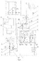
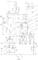
- Fig. 4 to Fig. 6 1-pressure switch SP, 2-directional valve (2a: first unit body, 201: electromagnetic directional valve, 2b: second unit body), 3-operating handle, 4-multi-way valve (401: oil filling piece, 401a: relief valve, 402: hoisting piece, 403: tilting piece, 404: oil returning piece), 5-tank, 6-check valve, 7-oil pump, 8-load sensing priority valve, 9-hoisting cylinder, 10-filter, 16-electric motor, 17-governor valve, 18-pressure switch latching valve, 19-intelligent display, 20-electrical storage device, 21-converter (with a controller).
- 4-multi-way valve 401: oil filling piece, 401a: relief valve, 402: hoisting piece, 403: tilting piece, 404: oil returning piece
- a switching control block with a pressure switch SP and an electromagnetic directional valve is additionally provided between a multi-way valve and a hoisting cylinder, as shown in Fig. 2 ;
- the function of the pressure switch SP is that: as the cargo will consume part of the electric energy when generating, only the cargo, of which the generating capacity is greater than the consumed electric energy for generating power, is the one which could be used for generating power, the SP is set by a demarcation point which is the lightest weight of the available cargo;
- the function of the directional valve is that: an electromagnet 1DT of the directional valve is not powered on when the cargo is in the hoisting operation, the pressure oil from a hoisting piece of the multi-way valve enters the hoisting cylinder via an A port and a P port of the directional valve to carry out the hoisting operation; when the cargo is in the lowering operation, whether the electromagnet of the directional valve is powered on could be carried out according to the instructions, when the cargo is in the lowering operation,
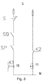
- a button S is additionally provided at an operating handle of the hoisting unit, as shown in Fig.
- the function thereof is that: if the operator does not want the system to enter a generation state in the lowering operation, the operator can press the button S to operate, at the moment, which is similar to the operation having no generation device; the energy collection process: when the electric forkarist truck forks the cargo and prepares to unload from the height, 1 the operator does not press the the hoisting piece handle button S of the multi-way valve when pushing the handle forwards, at the moment, the handle will trigger and switch on the lowering detection switch SQ at the hoisting piece.
- the pressure switch SP If the pressure corresponding to the cargo is greater than or equal to the pressure set by the pressure switch SP, the pressure switch SP is switched on, and the current flows into a coil of a relay via the two switches which are connected in series, the coil is powered on to make two pairs of normal open switches K1 and K2 of the relay closed.
- the K1 is closed so as to make the pin of an intelligent display or a driving module receive an electric signal, the intelligent display or the driving module program detects the signal of the pin and outputs the alternating current with set frequency corresponding to the pin, thus starting the electric motor of the pump and driving the gear pump to rotate.
- the K2 is closed so as to make the electromagnet 1DT of the directional valve of the control block powered on, the electromagnetic valve is reversed to enter the right position, the P port and B port of the directional valve are communicated; the pressure oil in the hoisting cylinder is filled into a pump via the governor valve, the P port and B port of the directional valve, and an F port of the pump.
- a check valve cuts off the pump to an inlet of a tank, the filled flow of the pressure oil is sufficient to make the pump operate with a rotating speed which exceeds that of the electric motor.
- the pump actually works in a motor state and drives the electric motor to rotate, and the electric motor works in the generation state.
- the current generated by the electric motor is converted by the driving module and charged into the battery, thus achieving the purpose of collecting the potential energy of the cargo.
- other operations could be carried out. If no other operations are carried out, the oil of the pump outlet enters the tank via a load sensing priority valve EF, and the unloading oil duct, without flow-saving function in median position, of the multi-way valve. At this time, the consumption quantity of power is minimum, and the generation quantity is maximum. If the pressure corresponding to the cargo is smaller than the pressure value set by the pressure switch SP, the pressure switch SP is not switched on, the coil of the relay will not be powered on, the normal open switches K1 and K2 of the relay will not be closed.
- the pin of the intelligent display or the driving module does not receive the signal, the electric motor of the pump will not be started, the electromagnet 1DT of the directional valve will not be powered on, the directional valve will not be reversed.
- the operation similar to the operation which has no generation device, could be carried out to lower cargo. 2 when the operator presses the hoisting piece handle button S of the multi-way valve and pushes the handle forwards, the operation, similar to the operation which has no generation device at the moment, could be carried out to lower the cargo, and this function is mainly used for the conditions which require the micro-action lowering operations.
- a switch K3 used as a fork swaying enabling switch is additionally provided at a walking accelerator, namely, the K3 is closed when operating the fork sideways, a frequency conversion driving module starts the electric motor with a steering frequency to drive the pump to operate, thus implementing the sideways operation.
- the pin originally connected to the sideways moving switch K1 is used as a generation pin, the lowering speed of the cargo during generation in the process of lowering could be controlled by setting the frequency corresponding to the pin.
- the directional valve 2 includes: a first reversing unit body 2a composed of a first cartridge valve C1, an electromagnetic directional valve 201, and a first damping orifice h1 connected with the first cartridge valve C1 and the electromagnetic directional valve 201; a second reversing unit orifice 2b composed of a second cartridge valve C2, the electromagnetic directional valve 201, and a second damping orifice h2 connected with the second cartridge valve C2 and a second control oil port PS2.
- a II port and a IV port of the first cartridge valve C1 are normally communicated.
- a I port is always capable of being communicated with the II port and the IV port, but the connection or disconnection from the II port and the IV port to the I port is under the control of the electromagnetic directional valve 201.
- a ii port and a iv port of the second cartridge valve C2 are normally communicated, the i port is always capable of being communicated with the ii port and the iv port, but the connection or disconnection from the ii port and the iv port to the i port is under the control of the electromagnetic directional valve 201.
- the electromagnetic directional valve 201 includes a first port d1, a second port d2, a third port d3 and a fourth port d4.
- the first port d1 is communicated with the third port d3, the second port d2 is communicated with the fourth port d4, and now, the IV port of the first cartridge valve C1 could be connected to the I port thereof, the iv port of the second cartridge valve C2 could not be communicated with the i port thereof.
- the electromagnetic directional valve 201 When the electromagnetic directional valve 201 is powered on, the first port d1 is communicated with the fourth port d4, the second port d2 is communicated with the third port d3, and now the IV port of the first cartridge valve C1 could not be communicated with the I port thereof, the iv port of the second cartridge valve C2 could be communicated with the i port thereof, the power on or off of the electromagnetic directional valve 201 respectively controls a control port of the first cartridge valve C1 or the second cartridge valve C2 to be in a communicated state.
- a first oil inlet P3 connected with the IV port of the first cartridge valve C1 is communicated with a working chamber of the hoisting cylinder 9 via the governor valve 17; a first oil outlet P2 connected with the I port of the first cartridge valve C1 is communicated with an A1 port of the multi-way valve 4; a second oil outlet P4 connected with the II port of the first cartridge valve C1 is communicated with a second oil inlet P5 of the second reversing unit body 2b; a first control oil port PS1 connected with the first port d1 of the electromagnetic directional valve 201 is communicated with the second control oil port PS2 of the second reversing unit body 2b; the first damping orifice h1 connected with a III port of the first cartridge valve C1 is communicated with the second port d2 of the electromagnetic directional valve 201; the second oil inlet P5 connected with the iv port of the second cartridge valve C2 is communicated with the second oil outlet P4; a third oil outlet P6 connected with the i port of
- auxiliary ports LC1 and LC2 are communicated with each other, and then are communicated to the general oil returning port T;
- the oil inlet P1 is communicated with the working port A1, the auxiliary ports LC1 and LC2 are not communicated;
- the working port A1 is communicated with the oil returning port T1, and the auxiliary ports LC1 and LC2 are communicated.
- the energy-recovery generation system for the handling and carrying electric vehicle further includes a first control mode constituted by the pressure switch latching valve 18, and a first branch constituted by connecting the hoisting piece handle button S, the enabling signaling switch SQ and the hoisting cylinder full-extension detection switch ST in series; a first sub-branch, constituted by the pressure switch SP and the relay K1 which are connected in series, and a second sub-branch, constituted by a coil of an electromagnet 2DT of the pressure switch latching valve 18, are connected in parallel at one end of the first branch, where the hoisting cylinder full-extension detection switch ST is located, to form a first control branch; the first normal open switch K1-1 and the coil of the electromagnet 1DT of the electromagnetic directional valve 201 of the directional valve 2 are connected in series to form a second control branch; a second normal open switch K1-2 provides a lowering enabling signal; the speed control signal potentiometer DW provides a lowering speed control signal; the lowering enabling signal
- the energy-recovery generation system for the handling and carrying electric vehicle further includes a second control mode constituted by a time relay KT and an intermediate relay K2.
- the time relay KT includes a first normal close switch KT-1
- the intermediate relay K2 includes a third normal open switch K2-1 and a second normal close switch K2-2.
- the hoisting piece handle button S, the enabling signaling switch SQ and the hoisting cylinder full-extension detection switch ST are connected in series to form the first branch; a I sub-branch constituted by the pressure switch SP, the first normal close switch KT-1 and a coil of the intermediate relay K2 which are connected in series is connected in parallel at one end of the first branch, where the hoisting cylinder full-extension detection switch ST is located; a second normal open switch K2-1 and the coil of the relay K1 are connected in series to form a II sub-branch; the second normal close switch K2-2 and the coil of the time relay KT are connected in series to form a III sub-branch, thus forming a third control branch.
- the first normal open switch K1-1 and the coil of the electromagnet 1DT of the electromagnetic directional valve 201 of the directional valve 2 are connected in series to form a second control branch.
- the second normal open switch K1-2 provides a lowering enabling signal;
- the speed control signal potentiometer DW provides a lowering speed control signal;
- the lowering enabling signal and the speed control signal are accessed to the intelligent display 19 or a controller of a converter 21.
- the energy-recovery generation system for the handling and carrying electric vehicle further includes a third control mode constituted by an intermediate relay K2, a resistor R and a transistor VT.
- the intermediate relay includes a first normal close switch K2-1 and a second normal close switch K2-2.
- the hoisting piece handle button S, the enabling signaling switch SQ and the hoisting cylinder full-extension detection switch ST are connected in series to form a first branch; a i sub-branch constituted by the normal close switch K2-1 and the coil of the relay K1 which are connected in series, a ii sub-branch constituted by the resistor R, the pressure switch SP and the second normal close switch K2-2 which are connected sin series, and a iii sub-branch constituted by the coil of the intermediate relay K2, and a collector and an emitter of the transistor VT which are connected in series are connected in parallel at one end of the first branch, where the hoisting cylinder full-extension detection switch ST is located, a base of the transistor VT is connected between the resistor R of the second sub-branch and the pressure switch SP, to form a fourth control branch; the first normal open switch K1-1 and the coil of the electromagnet 1DT of the electromagnetic directional valve 201 of the directional valve 2 are connected in series to form the second control
- the energy-recovery generation system for the handling and carrying electric vehicle wherein the energy storage device is a battery, a capacitor or a lithium battery.
- the energy-recovery generation system for the handling and carrying electric vehicle wherein a check valve is provided at the pipeline between the motor or pump inlet and the tank.
- the oil pump 7 adopts the hydraulic gear pump with motor function, a check valve 6 is additionally provided at the oil suction port; the check valve 6 has two functions:
- a pressure switch 1SP is additionally provided between the governor valve 17 and the hoisting cylinder 9, a first unit body 2a of the directional valve 2 is additionally provided between the multi-way valve 4 and the governor valve 17, a second unit body 2b of the directional valve 2 is additionally provided at the inlet of the motor or pump 7; the function of the pressure switch 1SP is that:
- the function of the pressure switch latching valve 18 is that:
- the function of the full-extension detection switch ST of the hoisting cylinder 9 is that: when the hoisting cylinder 9 fully extends in place, the pressure of the hoisting lowering without load at the moment, the signal collected by the pressure switch is an overflow pressure signal, and the signal meets the generation condition, the electric motor 16 will be started to generate power; however, no energy is recovered under non-load situation, while the power will be consumed in fact; In order to prevent such situation, it needs to set the full-extension detection switch ST of the hoisting cylinder 9.
- the lowering enabling switch SQ for detecting the cargo is additionally provided at the operating handle 3 or the valve rod of the hoisting piece of the control valve, the function thereof is to identify whether the operation is the lowering operation of the hoisting piece , if yes, powering on the switch to prepare for generation;
- the button S is additionally provided at the operating handle 3 of the hoisting piece of the control valve, the function thereof is that: if the operator does not want the system to enter the generation state in the lowering operation, the operator can press the button S to operate, and now, the operation is similar to the operation which has no generation device.
- the energy collection process when the electric forkarist truck forks the cargo and prepares to unload from the height, the operate can choose based on the requirements: 1 when the operator pushes the operating handle of the hoisting piece of the multi-way valve 4 forwards without pressing the button S, the operating handle 3 will trigger and power on the lowering enabling detection switch SQ provided at the hoisting piece.
- the pressure switch 1 SP is not switched on, the coil of K1 are not powered on, the normal open switches K1-1 and K1-2 of the relay K1 are not closed, the pin of the intelligent display 19 or the controller of the converter 21 does not receive the signal, and the electric motor 16 of the pump is not started, the electromagnet 1DT of the electromagnetic valve 201 of the first unit body 2a of the directional valve 2 is not powered on, at the moment, the P3 port and P2 port of the first unit body 2a of the directional valve 2 are communicated, however the second unit body 2b of the directional valve 2 and the oil suction port of the motor or oil pump 7 are disconnected, and now the lowering operations, similar to the original operation which has no generation device, could be operated to lower the cargo.
- the pressure switch 1 SP If the pressure corresponding to the cargo is greater than or equal to the set value of the pressure switch 1 SP, the pressure switch 1 SP is powered on, the current flows into the coil of relay K1 via the two switches which are connected in series, the coil are powered on as so to make the two pairs of the normal open switches K1-1 and K1-2 of the relay closed.
- the K1-2 is closed to make the pin of the intelligent display 19 or the controller of the converter 21 receives the electric signal, the driving program detects the signal of the pin and outputs the alternating current with the corresponding frequency, thus starting the electric motor 16 of the pump so as to drive the motor or the oil pump 7 to rotate.
- the K1-1 is closed to make the electromagnet 1DT of the electromagnetic directional valve 201 of the first unit body 2a of the directional valve 2 powered on, the electromagnetic valve is reversed to the left position, the P3 port and P2 port of the first unit body 2a of the directional valve 2 are cut off, the P5 port and P6 port of the second unit body 2b of the directional valve 2 are communicated, the pressure oil in the hoisting cylinder 9 flows into the inlet of the motor or the oil pump 7 via the governor valve 17, the P3 and P4 ports in the first unit body 2a of the directional valve 2, and the second unit body 2b of the directional valve 2; the check valve 6 at the inlet of the motor or oil pump 7 cuts off the oil duct between the inlet of the motor or oil pump 7 and the outlet of the tank 5.
- the flow of the pressure oil filled is sufficient to make the motor or oil pump 7 have the trend of operating with a speed which exceeds the synchronous rotating speed of the electric motor 16.
- the motor or oil pump 7 actually works in a motor state and drives the rotator of the electric motor 16 to rotate; the electric motor 16 works in a generation state, the current generated by the electric motor 16 is converted by the converter 21 and charged into the electrical storage device 20, thus achieving the purpose of collecting the potential energy of the cargo.
- the potentiometer DW which is under the control of the forward pushing stroke of the handle is further provided at the operating handle 3. The signal output by the potentiometer DW controls the synchronous rotating speed of the electric motor 16.
- the signal output by the potentiometer DW makes the electric motor 16 have a low synchronous rotating speed.
- the signal output by the potentiometer DW makes the electric motor 16 have a high synchronous rotating speed.
- the maximum rotating speed of the motor or oil pump 7 is controlled by the synchronous rotating speed of the electric motor 16 when lowering to generate power, thus the lowering speed of the cargo is finally controlled by the operating handle 3.
- the rotating direction of the electric motor 16 is not changed when lowering to generate power, the original operation will not be affected at all.
- the oil from the oil outlet of the motor or oil pump 7 enters the tank 5 via the load sensing directional valve 8EF and the unloading oil duct without the flow-saving function in the median position of the multi-way valve 4.
- the power consumption quantity is minimum, and the generation quantity is maximum. 2.
- the button S and pushes the operating handle 3 forwards the operation, similar to the operation which has no generation device, could be carried out to lower the cargo, and this button is mainly used for canceling the lowering generation function.
- the difference from the Fig. 4 is that: no pressure switch latching valve is provided at the hydraulic loop of the Fig. 5 and Fig. 6 .
- the Fig. 5 and Fig. 6 realize the following electrical principle: when the cargo, of which the weight pressure is close to the set value of the pressure switch 1, begins to lower, the pressure fluctuation in the pipeline between the hoisting cylinder 9 and the governor valve 17 is aroused due to the excessive speed of the operating handle, so that the directional valve 2 keeps reversing because the pressure switch 1SP is intermittently powered on and off, which causes the vibration in the lowering process of the cargo.
- the electrical principle of the Fig. 2 and Fig. 3 only locks the switch off of the pressure switch 1SP. If the pressure switch 1SP is switched off at the moment that the cargo begins to lower or in the subsequent process, the electrical control will quickly cut off the electrical branch where the pressure switch 1SP is located, and will not detect the state of the pressure switch 1SP anymore; the relay K1 will not be powered on, the potential energy of the cargo will not be recovered, thus removing the above adverse factors. With respect to other control processes, the Fig. 5 and Fig. 6 are similar to the Fig. 4 , and are not repeated.
Claims (8)
- Un véhicule électrique de manutention et de transport comprenant un système de génération de récupération d'énergie, comprenant un vérin de levage (9), dans lequel une canalisation de sortie du vérin de levage (9) est équipée d'une unité de capteur de pression (1) et un distributeur (2) ; le distributeur (2) est sous la commande de l'unité de capteur de pression (1) ; une première sortie du distributeur (2) est connectée à un réservoir (5) au moyen d'une vanne à voies multiples (4) comportant une poignée d'utilisation ; l'huile sous pression s'écoulant depuis une seconde sortie du distributeur (2), passe à travers une pompe (7) présentant un port d'aspiration d'huile susceptible de supporter la pression ou à travers un moteur et passe ensuite à travers la vanne à voies multiples (4), pour enfin s'écouler en sens inverse au réservoir (5) ; la pompe (7) présentant un port d'aspiration d'huile susceptible de supporter la pression ou le moteur entraîne un moteur électrique (16) pour produire l'énergie électrique ; une extrémité de sortie de l'énergie électrique du moteur électrique (16) est connectée à un dispositif de stockage d'énergie (20) au moyen d'un convertisseur (21) ;
le véhicule comprenant en outre un commutateur de signalisation d'activation de la détection d'abaissement de la cargaison (SQ), caractérisés par le véhicule électrique de manutention et de transport comprenant en outre un bouton de poignée de la pièce de levage (S) un potentiomètre du signal de commande de vitesse, (DW) et un relais (K1), dans lequel l'unité de capteur de pression comprend un manostat (SP) et un commutateur de détection d'extension complète du vérin de levage (ST), le relais (K1) comprend un premier commutateur normalement ouvert (K1-1) et un deuxième commutateur normalement ouvert (K1-2) ; le bouton de poignée de la pièce de levage (S), le commutateur de signalisation d'activation de la détection d'abaissement de la cargaison (SQ), le manostat (SP) et une bobine du relais (K1) sont connectés en série pour former une première branche de commande; le deuxième commutateur normalement ouvert (K1-2) du relais (K1) et une bobine (11) d'un électroaimant destinée à commander le distributeur (2) sont connectés en série pour former une deuxième branche de commande. - Le véhicule électrique de manutention et de transport selon la revendication 1, caractérisé en ce que la vanne à voies multiples (4) comportant la poignée de commande est une vanne à voies multiples à commande mécanique, une vanne à voies multiples à commande électrique, une vanne à voies multiples à commande hydraulique.
- Le véhicule électrique de manutention et de transport selon la revendication 1 ou la revendication 2, caractérisé en ce qu'une canalisation entre l'entrée de la pompe (7) présentant un port d'aspiration d'huile susceptible de supporter la pression ou le moteur et le réservoir (5) est équipé d'un clapet de non-retour.
- Le véhicule électrique de manutention et de transport selon la revendication 1, caractérisé en ce que le distributeur (2) comprend un premier corps d'unité d'inversion (2a) et un second corps d'unité d'inversion (2b) ; un chemin d'alimentation en huile est formé entre une sortie d'huile de la pompe (7) présentant un port d'aspiration d'huile susceptible de supporter la pression ou le moteur, la vanne à voies multiples (4), le distributeur (2) et une chambre de travail du vérin de levage (9) ; un premier chemin de décharge d'huile est formé entre la chambre de travail du vérin de levage (9), le premier corps d'unité d'inversion (2a) du distributeur (2), la vanne à voies multiples (4) et le réservoir (5) ; un second chemin de décharge d'huile est formé entre la chambre de travail du vérin de levage (9), le premier corps d'unité d'inversion (2a) et le second corps d'unité d'inversion (2b) du distributeur (2) et l'entrée d'huile de la pompe (7) présentant un port d'aspiration d'huile susceptible de supporter la pression ou le moteur ; et le premier chemin de décharge d'huile et le second chemin de décharge d'huile sont en communication de façon sélective par le distributeur (2) lorsque le vérin de levage (9) vidange l'huile.
- Le véhicule électrique de manutention et de transport selon la revendication 4, caractérisé en ce que le premier corps d'unité d'inversion (2a) comprend une première vanne à cartouche (C1), un distributeur électromagnétique (201), et un premier orifice d'amortissement (h1) connecté à la première vanne à cartouche (C1) et au distributeur électromagnétique (201); le second corps d'unité d'inversion (2b) comprend une seconde vanne à cartouche (C2), un distributeur électromagnétique (201) et un second orifice d'amortissement (h2) connecté à la seconde vanne à cartouche (C2) et à un second port d'huile de commande (PS2) ; un port II et un port IV de la première vanne à cartouche (C1) sont normalement en communication ; un port I de la première vanne à cartouche (C1) est toujours en communication avec le port II et le port IV et la connexion ou la déconnexion du port II et du port IV au port I est sous la commande du distributeur électromagnétique (201) ; un port i et un port iv de la seconde vanne à cartouche (C2) sont normalement en communication, le port i est toujours en communication avec le port ii et le port iv et la connexion ou la déconnexion du port ii et du port iv au port i est sous la commande du distributeur électromagnétique (201) et la mise sous tension ou hors tension du distributeur électromagnétique (201) commande respectivement le port de commande de la première vanne à cartouche (C1) ou celui de la seconde vanne à cartouche (C2) pour être dans un état de communication.
- Le véhicule électrique de manutention et de transport selon la revendication 1, comprenant en outre un premier mode de commande constitué par une vanne à verrouillage du manostat (18),
dans laquelle une première branche est constituée en connectant le bouton de poignée de la pièce de levage (S), le commutateur de signalisation d'activation (SQ) et le commutateur de détection d'extension complète du vérin de levage (ST) en série ; une première sous-branche constituée en connectant le manostat (SP) et le relais (K1) en série et une seconde sous-branche constituée par une bobine d'un électroaimant (2DT) de la vanne à verrouillage du manostat (18) sont connectées en parallèle à une extrémité de la première branche, où le commutateur de détection d'extension complète du vérin de levage (ST) est situé, pour former la première branche de commande ; le premier commutateur normalement ouvert (K1-1) et une bobine d'un électroaimant (1 DT) du distributeur électromagnétique (201) du distributeur (2) sont connectés en série pour former la deuxième branche de commande ; le deuxième commutateur normalement ouvert (K1-2) fournit un signal d'activation d'abaissement ; le potentiomètre du signal de commande de vitesse (DW) fournit un signal de commande de vitesse d'abaissement ; le signal d'activation d'abaissement et le signal de commande de vitesse sont accessibles par un affichage intelligent (19) ou un organe de commande du convertisseur (21). - Le véhicule électrique de manutention et de transport selon la revendication 1, comprenant en outre un second mode de commande constitué par un relais temporisé (KT) et un relais intermédiaire (K2), dans laquelle le relais temporisé (KT) comprend un premier commutateur normalement fermé (KT-1), le relais intermédiaire (K2) comprend un troisième commutateur normalement ouvert (K2-1) et un deuxième commutateur normalement fermé (K2-2) ; le bouton de poignée de la pièce de levage (S), le commutateur de signalisation d'activation (SQ) et le commutateur de détection d'extension complète du vérin de levage (DT) sont connectés en série pour former une première branche ; une sous-branche I constituée en connectant le manostat (SP), le premier commutateur normalement fermé (KT-1) et une bobine de relais intermédiaire (K2) en série, une sous-branche II constituée en connectant le troisième commutateur normalement fermé (K2-1) et la bobine du relais (K1) et une sous-branche III, constitué en connectant le deuxième commutateur normalement fermé (K2-2) et une bobine de relais temporisé (KT) en série sont connectés en parallèle à une extrémité de la première branche, où le commutateur de détection d'extension complète du vérin de levage (ST) est situé, pour former une troisième branche de commande ; le premier commutateur normalement ouvert (K1-1) et une bobine d'un électroaimant (1 DT) du distributeur électromagnétique (201) du distributeur (2) sont connectés en série pour former la deuxième branche de commande ; le deuxième commutateur normalement fermé (K1-2) fournit un signal d'activation d'abaissement ; le potentiomètre du signal de commande de vitesse (DW) fournit un signal de commande de vitesse d'abaissement ; le signal d'activation d'abaissement et le signal de commande de vitesse sont accessibles par un affichage intelligent (19) ou un organe de commande du convertisseur (21).
- Le véhicule électrique de manutention et de transport selon la revendication 1, comprenant en outre un troisième mode de commande constitué par un relais intermédiaire (K2), une résistance (R) et un transistor (VT) dans laquelle le relais intermédiaire comprend un premier commutateur normalement fermé (K2-1) et le deuxième commutateur normalement fermé (K2-2) ; le bouton de poignée de la pièce de levage (S), le commutateur de signalisation d'activation (SQ) et le commutateur de détection d'extension complète du vérin de levage (ST) sont connectés en série pour former une première branche ; une sous-branche i constituée en connectant le premier commutateur normalement fermé (K2-1) et la bobine de relais (K1) en série, une sous-branche ii constituée en connectant la résistance (R), le manostat (SP) et le deuxième commutateur normalement fermé (K2-2) en série et une sous-branche iii, constituée en connectant une bobine d'un relais intermédiaire (K2), un collecteur et un émetteur du transistor (VT) en série sont connectées en parallèle à une extrémité de la première branche, où le commutateur de détection d'extension complète du vérin de levage (ST) est situé ; une base du transistor (VT) est connectée entre la résistance (R) de la sous-branche ii et le manostat (SP) pour former une quatrième branche de commande; le premier commutateur normalement ouvert (K1-1) et une bobine d'un électroaimant (1 DT) du distributeur électromagnétique (201) du distributeur (2) sont connectés en série pour former la deuxième branche de commande ; le deuxième commutateur normalement fermé (K1-2) fournit un signal d'activation d'abaissement; le potentiomètre du signal de commande de vitesse (DW) fournit un signal de commande de vitesse d'abaissement ; le signal d'activation d'abaissement et le signal de commande de vitesse sont accessibles par un affichage intelligent (19) ou un organe de commande du convertisseur (21).
Applications Claiming Priority (2)
| Application Number | Priority Date | Filing Date | Title |
|---|---|---|---|
| CN2010106077920A CN102108948B (zh) | 2010-12-28 | 2010-12-28 | 一种适用于装卸搬运电动车的能量再生发电系统 |
| PCT/CN2011/083265 WO2012088991A1 (fr) | 2010-12-28 | 2011-11-30 | Système de production d'électricité à régénération d'énergie applicable à un véhicule pour le chargement, le déchargement et le transport |
Publications (3)
| Publication Number | Publication Date |
|---|---|
| EP2660184A1 EP2660184A1 (fr) | 2013-11-06 |
| EP2660184A4 EP2660184A4 (fr) | 2014-09-17 |
| EP2660184B1 true EP2660184B1 (fr) | 2016-03-16 |
Family
ID=44173204
Family Applications (1)
| Application Number | Title | Priority Date | Filing Date |
|---|---|---|---|
| EP11853792.7A Active EP2660184B1 (fr) | 2010-12-28 | 2011-11-30 | Système de production d'électricité à régénération d'énergie applicable à un véhicule pour le chargement, le déchargement et le transport |
Country Status (6)
| Country | Link |
|---|---|
| US (1) | US9422949B2 (fr) |
| EP (1) | EP2660184B1 (fr) |
| JP (1) | JP5914517B2 (fr) |
| CN (1) | CN102108948B (fr) |
| RU (1) | RU2603811C2 (fr) |
| WO (1) | WO2012088991A1 (fr) |
Families Citing this family (13)
| Publication number | Priority date | Publication date | Assignee | Title |
|---|---|---|---|---|
| KR20110127773A (ko) * | 2010-05-20 | 2011-11-28 | 두산산업차량 주식회사 | 전동지게차의 에너지 회수 시스템 |
| CN102108948B (zh) | 2010-12-28 | 2012-11-28 | 山河智能装备股份有限公司 | 一种适用于装卸搬运电动车的能量再生发电系统 |
| CN104495697B (zh) * | 2014-12-12 | 2017-01-11 | 牛力机械制造有限公司 | 一种延长电瓶叉车蓄电池工作时间的自动充电机构 |
| CN104828748B (zh) * | 2015-04-03 | 2017-03-29 | 柳州柳工叉车有限公司 | 叉车液压能量回收装置 |
| US10844880B2 (en) * | 2017-01-17 | 2020-11-24 | The Raymond Corporation | Variable hydraulic pressure relief systems and methods for a material handling vehicle |
| CN106995197A (zh) * | 2017-05-10 | 2017-08-01 | 安徽宇锋仓储设备有限公司 | 一种叉车升降液压控制方法 |
| CN107448440B (zh) * | 2017-09-15 | 2019-05-03 | 太原理工大学 | 背压和动力油电液复合调控多执行器系统 |
| CN109854570B (zh) * | 2019-01-07 | 2023-09-26 | 苏州瑞奇安机电科技有限公司 | 一种吸油减压装置以及吸油减压系统 |
| CN111102158A (zh) * | 2019-12-29 | 2020-05-05 | 袁菊花 | 吸污车的真空泵控制机构和启动机构的联动控制装置 |
| CN112408259A (zh) * | 2020-11-17 | 2021-02-26 | 山东大学日照智能制造研究院 | 一种料框自动夹取翻转运输装置及工作方法 |
| CN114619820B (zh) * | 2022-02-28 | 2023-12-01 | 安徽合力股份有限公司 | 基于摆动油缸容积变化的能量回收系统、方法及搬运车 |
| CN114704518A (zh) * | 2022-06-02 | 2022-07-05 | 宁波市博尔法液压有限公司 | 一种动力单元 |
| CN116146551B (zh) * | 2023-04-17 | 2023-08-22 | 山河智能装备股份有限公司 | 一种卷扬机构的液压系统及工程机械 |
Family Cites Families (27)
| Publication number | Priority date | Publication date | Assignee | Title |
|---|---|---|---|---|
| US2931182A (en) * | 1957-04-16 | 1960-04-05 | Cleveland Crane Eng | Hydraulic shear |
| US4614148A (en) * | 1979-08-20 | 1986-09-30 | Nl Industries, Inc. | Control valve system for blowout preventers |
| JPS56108700A (en) * | 1980-01-28 | 1981-08-28 | Nissan Motor | Battery fork lift |
| US4396087A (en) * | 1981-04-24 | 1983-08-02 | International Harvester Co. | Auxiliary drive system for combines |
| SU1260330A1 (ru) * | 1985-04-11 | 1986-09-30 | Псковский Филиал Ленинградского Ордена Ленина Политехнического Института Им.М.И.Калинина | Гидропривод погрузчика |
| DE3602510A1 (de) * | 1986-01-28 | 1987-07-30 | Steinbock Gmbh | Hydraulisches hubwerk |
| JPS63230497A (ja) * | 1987-03-20 | 1988-09-26 | 日産自動車株式会社 | 産業車両の荷役装置 |
| SU1677020A1 (ru) * | 1989-04-24 | 1991-09-15 | Новочеркасский политехнический институт им.С.Орджоникидзе | Механизм вертикального перемещени грузоподъемника крана-штабелера |
| JPH033897A (ja) | 1989-05-31 | 1991-01-09 | Toyota Autom Loom Works Ltd | バッテリ式産業車両における油圧装置 |
| JP3186473B2 (ja) * | 1994-11-10 | 2001-07-11 | 神鋼電機株式会社 | 油圧制御装置 |
| DE69731256T2 (de) * | 1996-06-19 | 2006-03-02 | Kabushiki Kaisha Kobe Seiko Sho Also Known As Kobe Steel Ltd. | Batteriebetriebene Baumaschine |
| US5936375A (en) * | 1997-11-05 | 1999-08-10 | Paceco Corp. | Method for energy storage for load hoisting machinery |
| DE50111349D1 (de) | 2000-09-18 | 2006-12-14 | Still Gmbh | Hubvorrichtung |
| US6877417B2 (en) * | 2001-04-17 | 2005-04-12 | Shin Caterpillar Mitsubishi Ltd. | Fluid pressure circuit |
| JP3679749B2 (ja) * | 2001-10-19 | 2005-08-03 | サクサ株式会社 | 油圧装置 |
| DE10154449A1 (de) | 2001-11-06 | 2003-05-15 | Dambach Lagersysteme Gmbh & Co | Hydraulische Hubvorrichtung insbesondere für batteriegetriebene Flurförderzeuge und Verfahren zu deren Steuerung |
| JP3957061B2 (ja) * | 2002-07-08 | 2007-08-08 | 株式会社小松製作所 | 複数の圧油エネルギー選択回収装置及びその選択回収方法 |
| EP1852388B1 (fr) * | 2005-02-25 | 2013-04-03 | Mitsubishi Heavy Industries, Ltd. | Systeme de regeneration de la capacite de gestion de la charge pour vehicule industriel a batteries d'accumulateurs |
| EP1852387B1 (fr) * | 2005-02-25 | 2013-04-03 | Mitsubishi Heavy Industries, Ltd. | Procede et systeme de recuperation d'energie de manutention sur vehicule industriel alimente par batterie |
| RU2309890C2 (ru) * | 2005-12-15 | 2007-11-10 | Ефим Маркович Певзнер | Устройство управления электроприводом механизма подъема и опускания груза грузоподъемного крана |
| CN100386254C (zh) | 2006-03-31 | 2008-05-07 | 西安交通大学 | 一种能量回收式电动叉车举升控制系统 |
| JP4969164B2 (ja) | 2006-06-28 | 2012-07-04 | 日本輸送機株式会社 | 昇降装置 |
| JP2008087914A (ja) * | 2006-10-02 | 2008-04-17 | Toyota Industries Corp | 荷役装置のエネルギー回収装置 |
| CN101220823A (zh) | 2006-11-14 | 2008-07-16 | 胡斯可国际股份有限公司 | 用于液压系统的能量回收与再利用技术 |
| DE502007003962D1 (de) | 2007-11-06 | 2010-07-08 | Hawe Hydraulik Se | Elektrohydraulische Hubvorrichtung |
| CN102108948B (zh) * | 2010-12-28 | 2012-11-28 | 山河智能装备股份有限公司 | 一种适用于装卸搬运电动车的能量再生发电系统 |
| CN201953584U (zh) * | 2010-12-28 | 2011-08-31 | 湖南山河智能机械股份有限公司 | 一种适用于装卸搬运电动车的能量再生发电系统 |
-
2010
- 2010-12-28 CN CN2010106077920A patent/CN102108948B/zh active Active
-
2011
- 2011-11-30 US US13/977,100 patent/US9422949B2/en active Active
- 2011-11-30 EP EP11853792.7A patent/EP2660184B1/fr active Active
- 2011-11-30 JP JP2013546572A patent/JP5914517B2/ja active Active
- 2011-11-30 RU RU2013131757/11A patent/RU2603811C2/ru active
- 2011-11-30 WO PCT/CN2011/083265 patent/WO2012088991A1/fr active Application Filing
Also Published As
| Publication number | Publication date |
|---|---|
| RU2013131757A (ru) | 2015-02-10 |
| US20130283776A1 (en) | 2013-10-31 |
| WO2012088991A1 (fr) | 2012-07-05 |
| CN102108948B (zh) | 2012-11-28 |
| JP2014502588A (ja) | 2014-02-03 |
| EP2660184A4 (fr) | 2014-09-17 |
| JP5914517B2 (ja) | 2016-05-11 |
| US9422949B2 (en) | 2016-08-23 |
| CN102108948A (zh) | 2011-06-29 |
| RU2603811C2 (ru) | 2016-11-27 |
| EP2660184A1 (fr) | 2013-11-06 |
Similar Documents
| Publication | Publication Date | Title |
|---|---|---|
| EP2660184B1 (fr) | Système de production d'électricité à régénération d'énergie applicable à un véhicule pour le chargement, le déchargement et le transport | |
| US8807155B2 (en) | Control device for hybrid construction machine | |
| CN108978775B (zh) | 一种基于飞轮的挖掘机用混联式机械混合动力系统 | |
| CN108502816B (zh) | 旁通式能量再生叉车液压系统 | |
| CN109764027B (zh) | 具有能量回收功能的电液压作业车辆 | |
| CN108894274B (zh) | 一种挖掘机回转能量回收和再利用系统 | |
| EP2444555B1 (fr) | Excavateur | |
| JP2011017425A (ja) | ハイブリッド建設機械の制御装置 | |
| CN109797797B (zh) | 一种扭矩耦合式挖掘机动臂势能回收与再利用系统 | |
| CN108978774B (zh) | 一种用于挖掘机的混联式混合动力系统 | |
| CN103950870A (zh) | 一种双泵供油带能量回收的叉车液压系统 | |
| CN112249986A (zh) | 基于多液压马达-蓄能器组合电动叉车的能量回收系统 | |
| CN203428881U (zh) | 臂架或梯架的液压控制系统 | |
| CN103015725A (zh) | 臂架液压系统及其控制方法、臂架系统和混凝土泵送设备 | |
| CN208454429U (zh) | 旁通式能量再生叉车液压系统 | |
| CN112594240B (zh) | 一种工作装置液压系统、控制方法及电动装载机 | |
| CN107345411B (zh) | 动臂油缸节能系统及其控制方法、挖掘机 | |
| CN212317029U (zh) | 基于飞轮的挖掘机用混联式机械混合动力系统 | |
| CN103183296B (zh) | 一种泵电机同向下降发电控制系统 | |
| CN108302074B (zh) | 一种电动叉车的能量再生系统及控制方法 | |
| CN109336005B (zh) | 一种电动叉车用外接节能装置及节能控制方法 | |
| CN201914850U (zh) | 一种起重机及其液压控制系统 | |
| CN201953584U (zh) | 一种适用于装卸搬运电动车的能量再生发电系统 | |
| JP2011017426A (ja) | ハイブリッド建設機械の制御装置 | |
| JPH02163300A (ja) | バッテリ式産業車両における油圧装置 |
Legal Events
| Date | Code | Title | Description |
|---|---|---|---|
| PUAI | Public reference made under article 153(3) epc to a published international application that has entered the european phase |
Free format text: ORIGINAL CODE: 0009012 |
|
| 17P | Request for examination filed |
Effective date: 20130705 |
|
| AK | Designated contracting states |
Kind code of ref document: A1 Designated state(s): AL AT BE BG CH CY CZ DE DK EE ES FI FR GB GR HR HU IE IS IT LI LT LU LV MC MK MT NL NO PL PT RO RS SE SI SK SM TR |
|
| DAX | Request for extension of the european patent (deleted) | ||
| A4 | Supplementary search report drawn up and despatched |
Effective date: 20140820 |
|
| RIC1 | Information provided on ipc code assigned before grant |
Ipc: F15B 15/18 20060101ALI20140813BHEP Ipc: F15B 21/14 20060101ALI20140813BHEP Ipc: B66F 9/22 20060101AFI20140813BHEP |
|
| GRAP | Despatch of communication of intention to grant a patent |
Free format text: ORIGINAL CODE: EPIDOSNIGR1 |
|
| INTG | Intention to grant announced |
Effective date: 20151005 |
|
| GRAS | Grant fee paid |
Free format text: ORIGINAL CODE: EPIDOSNIGR3 |
|
| GRAA | (expected) grant |
Free format text: ORIGINAL CODE: 0009210 |
|
| AK | Designated contracting states |
Kind code of ref document: B1 Designated state(s): AL AT BE BG CH CY CZ DE DK EE ES FI FR GB GR HR HU IE IS IT LI LT LU LV MC MK MT NL NO PL PT RO RS SE SI SK SM TR |
|
| REG | Reference to a national code |
Ref country code: GB Ref legal event code: FG4D |
|
| REG | Reference to a national code |
Ref country code: CH Ref legal event code: EP |
|
| REG | Reference to a national code |
Ref country code: IE Ref legal event code: FG4D |
|
| REG | Reference to a national code |
Ref country code: AT Ref legal event code: REF Ref document number: 781034 Country of ref document: AT Kind code of ref document: T Effective date: 20160415 |
|
| REG | Reference to a national code |
Ref country code: DE Ref legal event code: R096 Ref document number: 602011024185 Country of ref document: DE |
|
| REG | Reference to a national code |
Ref country code: NL Ref legal event code: MP Effective date: 20160316 |
|
| REG | Reference to a national code |
Ref country code: LT Ref legal event code: MG4D |
|
| PG25 | Lapsed in a contracting state [announced via postgrant information from national office to epo] |
Ref country code: HR Free format text: LAPSE BECAUSE OF FAILURE TO SUBMIT A TRANSLATION OF THE DESCRIPTION OR TO PAY THE FEE WITHIN THE PRESCRIBED TIME-LIMIT Effective date: 20160316 Ref country code: FI Free format text: LAPSE BECAUSE OF FAILURE TO SUBMIT A TRANSLATION OF THE DESCRIPTION OR TO PAY THE FEE WITHIN THE PRESCRIBED TIME-LIMIT Effective date: 20160316 Ref country code: NO Free format text: LAPSE BECAUSE OF FAILURE TO SUBMIT A TRANSLATION OF THE DESCRIPTION OR TO PAY THE FEE WITHIN THE PRESCRIBED TIME-LIMIT Effective date: 20160616 Ref country code: GR Free format text: LAPSE BECAUSE OF FAILURE TO SUBMIT A TRANSLATION OF THE DESCRIPTION OR TO PAY THE FEE WITHIN THE PRESCRIBED TIME-LIMIT Effective date: 20160617 |
|
| REG | Reference to a national code |
Ref country code: AT Ref legal event code: MK05 Ref document number: 781034 Country of ref document: AT Kind code of ref document: T Effective date: 20160316 |
|
| PG25 | Lapsed in a contracting state [announced via postgrant information from national office to epo] |
Ref country code: RS Free format text: LAPSE BECAUSE OF FAILURE TO SUBMIT A TRANSLATION OF THE DESCRIPTION OR TO PAY THE FEE WITHIN THE PRESCRIBED TIME-LIMIT Effective date: 20160316 Ref country code: NL Free format text: LAPSE BECAUSE OF FAILURE TO SUBMIT A TRANSLATION OF THE DESCRIPTION OR TO PAY THE FEE WITHIN THE PRESCRIBED TIME-LIMIT Effective date: 20160316 Ref country code: LT Free format text: LAPSE BECAUSE OF FAILURE TO SUBMIT A TRANSLATION OF THE DESCRIPTION OR TO PAY THE FEE WITHIN THE PRESCRIBED TIME-LIMIT Effective date: 20160316 Ref country code: LV Free format text: LAPSE BECAUSE OF FAILURE TO SUBMIT A TRANSLATION OF THE DESCRIPTION OR TO PAY THE FEE WITHIN THE PRESCRIBED TIME-LIMIT Effective date: 20160316 Ref country code: SE Free format text: LAPSE BECAUSE OF FAILURE TO SUBMIT A TRANSLATION OF THE DESCRIPTION OR TO PAY THE FEE WITHIN THE PRESCRIBED TIME-LIMIT Effective date: 20160316 |
|
| PG25 | Lapsed in a contracting state [announced via postgrant information from national office to epo] |
Ref country code: IS Free format text: LAPSE BECAUSE OF FAILURE TO SUBMIT A TRANSLATION OF THE DESCRIPTION OR TO PAY THE FEE WITHIN THE PRESCRIBED TIME-LIMIT Effective date: 20160716 Ref country code: EE Free format text: LAPSE BECAUSE OF FAILURE TO SUBMIT A TRANSLATION OF THE DESCRIPTION OR TO PAY THE FEE WITHIN THE PRESCRIBED TIME-LIMIT Effective date: 20160316 Ref country code: PL Free format text: LAPSE BECAUSE OF FAILURE TO SUBMIT A TRANSLATION OF THE DESCRIPTION OR TO PAY THE FEE WITHIN THE PRESCRIBED TIME-LIMIT Effective date: 20160316 |
|
| REG | Reference to a national code |
Ref country code: FR Ref legal event code: PLFP Year of fee payment: 6 |
|
| PG25 | Lapsed in a contracting state [announced via postgrant information from national office to epo] |
Ref country code: AT Free format text: LAPSE BECAUSE OF FAILURE TO SUBMIT A TRANSLATION OF THE DESCRIPTION OR TO PAY THE FEE WITHIN THE PRESCRIBED TIME-LIMIT Effective date: 20160316 Ref country code: PT Free format text: LAPSE BECAUSE OF FAILURE TO SUBMIT A TRANSLATION OF THE DESCRIPTION OR TO PAY THE FEE WITHIN THE PRESCRIBED TIME-LIMIT Effective date: 20160718 Ref country code: CZ Free format text: LAPSE BECAUSE OF FAILURE TO SUBMIT A TRANSLATION OF THE DESCRIPTION OR TO PAY THE FEE WITHIN THE PRESCRIBED TIME-LIMIT Effective date: 20160316 Ref country code: SM Free format text: LAPSE BECAUSE OF FAILURE TO SUBMIT A TRANSLATION OF THE DESCRIPTION OR TO PAY THE FEE WITHIN THE PRESCRIBED TIME-LIMIT Effective date: 20160316 Ref country code: RO Free format text: LAPSE BECAUSE OF FAILURE TO SUBMIT A TRANSLATION OF THE DESCRIPTION OR TO PAY THE FEE WITHIN THE PRESCRIBED TIME-LIMIT Effective date: 20160316 Ref country code: SK Free format text: LAPSE BECAUSE OF FAILURE TO SUBMIT A TRANSLATION OF THE DESCRIPTION OR TO PAY THE FEE WITHIN THE PRESCRIBED TIME-LIMIT Effective date: 20160316 Ref country code: ES Free format text: LAPSE BECAUSE OF FAILURE TO SUBMIT A TRANSLATION OF THE DESCRIPTION OR TO PAY THE FEE WITHIN THE PRESCRIBED TIME-LIMIT Effective date: 20160316 |
|
| REG | Reference to a national code |
Ref country code: DE Ref legal event code: R097 Ref document number: 602011024185 Country of ref document: DE |
|
| PG25 | Lapsed in a contracting state [announced via postgrant information from national office to epo] |
Ref country code: IT Free format text: LAPSE BECAUSE OF FAILURE TO SUBMIT A TRANSLATION OF THE DESCRIPTION OR TO PAY THE FEE WITHIN THE PRESCRIBED TIME-LIMIT Effective date: 20160316 |
|
| PLBE | No opposition filed within time limit |
Free format text: ORIGINAL CODE: 0009261 |
|
| STAA | Information on the status of an ep patent application or granted ep patent |
Free format text: STATUS: NO OPPOSITION FILED WITHIN TIME LIMIT |
|
| PG25 | Lapsed in a contracting state [announced via postgrant information from national office to epo] |
Ref country code: DK Free format text: LAPSE BECAUSE OF FAILURE TO SUBMIT A TRANSLATION OF THE DESCRIPTION OR TO PAY THE FEE WITHIN THE PRESCRIBED TIME-LIMIT Effective date: 20160316 |
|
| 26N | No opposition filed |
Effective date: 20161219 |
|
| PG25 | Lapsed in a contracting state [announced via postgrant information from national office to epo] |
Ref country code: BG Free format text: LAPSE BECAUSE OF FAILURE TO SUBMIT A TRANSLATION OF THE DESCRIPTION OR TO PAY THE FEE WITHIN THE PRESCRIBED TIME-LIMIT Effective date: 20160616 |
|
| PG25 | Lapsed in a contracting state [announced via postgrant information from national office to epo] |
Ref country code: SI Free format text: LAPSE BECAUSE OF FAILURE TO SUBMIT A TRANSLATION OF THE DESCRIPTION OR TO PAY THE FEE WITHIN THE PRESCRIBED TIME-LIMIT Effective date: 20160316 |
|
| REG | Reference to a national code |
Ref country code: DE Ref legal event code: R119 Ref document number: 602011024185 Country of ref document: DE |
|
| REG | Reference to a national code |
Ref country code: CH Ref legal event code: PL |
|
| GBPC | Gb: european patent ceased through non-payment of renewal fee |
Effective date: 20161130 |
|
| PG25 | Lapsed in a contracting state [announced via postgrant information from national office to epo] |
Ref country code: CH Free format text: LAPSE BECAUSE OF NON-PAYMENT OF DUE FEES Effective date: 20161130 Ref country code: LI Free format text: LAPSE BECAUSE OF NON-PAYMENT OF DUE FEES Effective date: 20161130 |
|
| REG | Reference to a national code |
Ref country code: IE Ref legal event code: MM4A |
|
| PG25 | Lapsed in a contracting state [announced via postgrant information from national office to epo] |
Ref country code: LU Free format text: LAPSE BECAUSE OF NON-PAYMENT OF DUE FEES Effective date: 20161130 |
|
| REG | Reference to a national code |
Ref country code: FR Ref legal event code: PLFP Year of fee payment: 7 |
|
| PG25 | Lapsed in a contracting state [announced via postgrant information from national office to epo] |
Ref country code: IE Free format text: LAPSE BECAUSE OF NON-PAYMENT OF DUE FEES Effective date: 20161130 Ref country code: DE Free format text: LAPSE BECAUSE OF NON-PAYMENT OF DUE FEES Effective date: 20170601 Ref country code: GB Free format text: LAPSE BECAUSE OF NON-PAYMENT OF DUE FEES Effective date: 20161130 |
|
| PG25 | Lapsed in a contracting state [announced via postgrant information from national office to epo] |
Ref country code: CY Free format text: LAPSE BECAUSE OF FAILURE TO SUBMIT A TRANSLATION OF THE DESCRIPTION OR TO PAY THE FEE WITHIN THE PRESCRIBED TIME-LIMIT Effective date: 20160316 Ref country code: HU Free format text: LAPSE BECAUSE OF FAILURE TO SUBMIT A TRANSLATION OF THE DESCRIPTION OR TO PAY THE FEE WITHIN THE PRESCRIBED TIME-LIMIT; INVALID AB INITIO Effective date: 20111130 |
|
| PG25 | Lapsed in a contracting state [announced via postgrant information from national office to epo] |
Ref country code: MK Free format text: LAPSE BECAUSE OF FAILURE TO SUBMIT A TRANSLATION OF THE DESCRIPTION OR TO PAY THE FEE WITHIN THE PRESCRIBED TIME-LIMIT Effective date: 20160316 Ref country code: MC Free format text: LAPSE BECAUSE OF FAILURE TO SUBMIT A TRANSLATION OF THE DESCRIPTION OR TO PAY THE FEE WITHIN THE PRESCRIBED TIME-LIMIT Effective date: 20160316 |
|
| PG25 | Lapsed in a contracting state [announced via postgrant information from national office to epo] |
Ref country code: MT Free format text: LAPSE BECAUSE OF NON-PAYMENT OF DUE FEES Effective date: 20161130 |
|
| PG25 | Lapsed in a contracting state [announced via postgrant information from national office to epo] |
Ref country code: TR Free format text: LAPSE BECAUSE OF FAILURE TO SUBMIT A TRANSLATION OF THE DESCRIPTION OR TO PAY THE FEE WITHIN THE PRESCRIBED TIME-LIMIT Effective date: 20160316 Ref country code: AL Free format text: LAPSE BECAUSE OF FAILURE TO SUBMIT A TRANSLATION OF THE DESCRIPTION OR TO PAY THE FEE WITHIN THE PRESCRIBED TIME-LIMIT Effective date: 20160316 |
|
| PGFP | Annual fee paid to national office [announced via postgrant information from national office to epo] |
Ref country code: FR Payment date: 20231123 Year of fee payment: 13 |
|
| PGFP | Annual fee paid to national office [announced via postgrant information from national office to epo] |
Ref country code: BE Payment date: 20231121 Year of fee payment: 13 |