EP2659009B1 - Mehrfach gesicherte koppelvorrichtung für sauerstofflanzen - Google Patents
Mehrfach gesicherte koppelvorrichtung für sauerstofflanzen Download PDFInfo
- Publication number
- EP2659009B1 EP2659009B1 EP11817466.3A EP11817466A EP2659009B1 EP 2659009 B1 EP2659009 B1 EP 2659009B1 EP 11817466 A EP11817466 A EP 11817466A EP 2659009 B1 EP2659009 B1 EP 2659009B1
- Authority
- EP
- European Patent Office
- Prior art keywords
- coupling device
- accordance
- sealing
- connecting part
- plug
- Prior art date
- Legal status (The legal status is an assumption and is not a legal conclusion. Google has not performed a legal analysis and makes no representation as to the accuracy of the status listed.)
- Active
Links
- 230000008878 coupling Effects 0.000 title claims description 40
- 238000010168 coupling process Methods 0.000 title claims description 40
- 238000005859 coupling reaction Methods 0.000 title claims description 40
- 239000001301 oxygen Substances 0.000 title claims description 14
- 229910052760 oxygen Inorganic materials 0.000 title claims description 14
- QVGXLLKOCUKJST-UHFFFAOYSA-N atomic oxygen Chemical compound [O] QVGXLLKOCUKJST-UHFFFAOYSA-N 0.000 title claims description 13
- 238000007789 sealing Methods 0.000 claims description 78
- 239000007789 gas Substances 0.000 claims description 10
- 230000000694 effects Effects 0.000 claims description 7
- 229910001220 stainless steel Inorganic materials 0.000 claims description 4
- 239000010935 stainless steel Substances 0.000 claims description 4
- 229910001369 Brass Inorganic materials 0.000 claims description 2
- 239000010951 brass Substances 0.000 claims description 2
- 239000000161 steel melt Substances 0.000 claims 1
- 239000002184 metal Substances 0.000 description 5
- 229910000831 Steel Inorganic materials 0.000 description 3
- 239000010959 steel Substances 0.000 description 3
- 230000009286 beneficial effect Effects 0.000 description 1
- 239000002737 fuel gas Substances 0.000 description 1
- 238000003780 insertion Methods 0.000 description 1
- 230000037431 insertion Effects 0.000 description 1
- 230000013011 mating Effects 0.000 description 1
- 238000003032 molecular docking Methods 0.000 description 1
- 150000002926 oxygen Chemical class 0.000 description 1
- 230000000717 retained effect Effects 0.000 description 1
- 238000000926 separation method Methods 0.000 description 1
Images
Classifications
-
- F—MECHANICAL ENGINEERING; LIGHTING; HEATING; WEAPONS; BLASTING
- F16—ENGINEERING ELEMENTS AND UNITS; GENERAL MEASURES FOR PRODUCING AND MAINTAINING EFFECTIVE FUNCTIONING OF MACHINES OR INSTALLATIONS; THERMAL INSULATION IN GENERAL
- F16L—PIPES; JOINTS OR FITTINGS FOR PIPES; SUPPORTS FOR PIPES, CABLES OR PROTECTIVE TUBING; MEANS FOR THERMAL INSULATION IN GENERAL
- F16L19/00—Joints in which sealing surfaces are pressed together by means of a member, e.g. a swivel nut, screwed on or into one of the joint parts
- F16L19/02—Pipe ends provided with collars or flanges, integral with the pipe or not, pressed together by a screwed member
-
- C—CHEMISTRY; METALLURGY
- C21—METALLURGY OF IRON
- C21C—PROCESSING OF PIG-IRON, e.g. REFINING, MANUFACTURE OF WROUGHT-IRON OR STEEL; TREATMENT IN MOLTEN STATE OF FERROUS ALLOYS
- C21C5/00—Manufacture of carbon-steel, e.g. plain mild steel, medium carbon steel or cast steel or stainless steel
- C21C5/28—Manufacture of steel in the converter
- C21C5/42—Constructional features of converters
- C21C5/46—Details or accessories
- C21C5/4606—Lances or injectors
- C21C5/462—Means for handling, e.g. adjusting, changing, coupling
-
- F—MECHANICAL ENGINEERING; LIGHTING; HEATING; WEAPONS; BLASTING
- F16—ENGINEERING ELEMENTS AND UNITS; GENERAL MEASURES FOR PRODUCING AND MAINTAINING EFFECTIVE FUNCTIONING OF MACHINES OR INSTALLATIONS; THERMAL INSULATION IN GENERAL
- F16L—PIPES; JOINTS OR FITTINGS FOR PIPES; SUPPORTS FOR PIPES, CABLES OR PROTECTIVE TUBING; MEANS FOR THERMAL INSULATION IN GENERAL
- F16L19/00—Joints in which sealing surfaces are pressed together by means of a member, e.g. a swivel nut, screwed on or into one of the joint parts
- F16L19/02—Pipe ends provided with collars or flanges, integral with the pipe or not, pressed together by a screwed member
- F16L19/025—Pipe ends provided with collars or flanges, integral with the pipe or not, pressed together by a screwed member the pipe ends having integral collars or flanges
Definitions
- the invention relates to a multiply secured coupling device for oxygen lances and other, flammable gases leading and injecting these media in the molten steel tubes, which have a designed as a valve lance holder and a safety tube, which is arranged between the lance holder and a lance tube leading to the supplier or directly connected to the supplier.
- a burner tube holder or an oxygen lance with lance holder is for example from EP 0 372 099 B1 known. At the oxygen inlet of this lance holder, however, only a thread is indicated, on which a safety tube, not shown here, is screwed.
- a safety tube not shown here.
- Such usually made of stainless steel safety pipes or safety routes are helpful in manually operated lance holders and serve above all to increase the reliability, because it is to be achieved through the proper management of flammable gases especially the oxygen to the lance holder. It is difficult, however, if traded carelessly in the coupling device between the oxygen lance and the safety route or the safety tube and the coupling device is not tightened enough, because then the leakage of highly flammable gas can still occur.
- the coupling device is always tightened to ensure the tightness of the connection. In case of carelessness, however, the described hazard is still present.
- the sealing ring is assigned to the male part and has an oblique sealing surface.
- the JP 58 132335 includes a burner having supply channels for oxygen and fuel gas.
- the EP 1 159 513 A concerns such a burner.
- the DE 10 2009 005 940 B3 becomes taught a mounting system in which components are connected via a union nut.
- the DE 10 2008 012 534 A1 has a lance holder to the object, which can be connected to a lance tube or a safety tube.
- the invention is therefore an object of the invention to provide a coupling device for oxygen supply lines in steel mills, in which dangerous leaks are approximately avoided, if possible even completely excluded.
- the safety tube has an insertable into the connection part of the lance holder male part which forms the coupling device with a screw on the lance holder union coupling and as well as connector and union nut is extended by a security piece that a wide insertion in the connection part permitting and thus a sealing effect even with loose seated union nut guaranteed formed and equipped with at least one against the connection part of the lance holder in the region of sealing surfaces sealing, the free end of the connecting part associated ring seal and on the other hand an elongated thread which is associated with the ring seal Sealing surface area of the sealing surface on the extended plug-in part makes up 33-50% of the sealing surface area, which is formed only by the connecting part and plug-in part.
- Connecting part, union nut and plug-in part are formed extended by a security piece, wherein the ring seal associated sealing surface area is significantly shorter than the only formed by the connecting part and plug-in sealing surface area, so it is clear which dimensioning of the security piece in all three components has to be expediently
- a trained coupling device between oxygen lance and safety tube is also the necessary security guaranteed if the nut is not one hundred percent tightened.
- both the connection part and the union nut as well as the plug-in part are extended once to an additional sealing zone create and on the other hand in order to ensure the necessary tightness of the system in the loose arrangement of the union nut nevertheless by the extended plug-in part and the suitably mounted ring seal.
- the ring seal is arranged so that the plug-in part can be inserted far into the connection part of the lance holder and the ring seal is arranged only at the free end of the connection part.
- the ring seal is thus still effective even if the male part is pulled out of the male part by a certain range by a loose union nut.
- the ring seal is formed by two arranged in spaced annular grooves O-rings wherein the male part has over the O-rings of the ring seal projecting free sealing surface area, which is twice as large as that of the two O-rings Covered sealing surface area.
- connection part of the lance holder serves as an extended female part and is designed to have frictional annular seal on the correspondingly extended and serving as a male part male part of the safety tube or lance tube.
- the male part of the safety tube serving as a plug part is associated with a corresponding with the external thread of the connecting part internal thread. Since both threaded areas are the same length and the same shape, the necessary secure connection between the safety tube and lance holder can be ensured with the appropriate union nut.
- the invention provides for this purpose that the male part has a support ring, against the inner surface formed as a sealing surface, the free end of the connecting part of the lance holder can be pressed via the sliding on the external thread union nut.
- the ring seal is thus arranged in the connection part of the lance holder in the extended nut part, that a sealing effect is still present even if the plug-in part is slightly pulled out of the connection part with loose-fitting cap nut. As defined in claim 1, this is ensured by the fact that the ring seal is assigned to the free end of the connecting part and as far as possible at the free end, so as to maintain the said securing the connection as long as possible.
- the lance tube is connected to the safety tube.
- the safety tube has a counterpart connection part designed in accordance with the connection part of the lance holder.
- the lance tube receives accordingly a male part, which corresponds to the male part of the safety tube, so that thus an equally advantageous connection is possible, as with the lance holder.
- the present invention receives the fact that in the deepest part of the connecting part of the lance holder at the same time serving as a stop for the male part ring web is formed. This can be sealed by acting on the union nut at the same time lying in the lowest sealing zone and in the region of the support ring, so that together with the ring seal virtually four sealing zones are present, which are beneficial for the advantageous sealing effect of the coupling device.
- the nut itself is also designed to be extended, as the male part and the connector, which is provided according to an advantageous embodiment that the nut is formed having ten to twenty threads, while conventional union nuts have only five to seven threads. This makes it clear that even over the longer thread additional security is given, since even with a slightly loosened union nut still sufficient thread is present to exclude a separation and thus a complete leak.
- a durable easy production of the connection between the lance holder and safety tube on the coupling device is given in particular, if the union nut made of brass and the male part as well as the rest of the safety tube are made of stainless steel.
- the union nut of the less hard metal can thus be easily screwed onto the likewise made of stainless steel connecting part of the lance holder.
- Another sealing zone is created between the support ring and the free end of the connection part and without a separate sealing ring.
- the existing on the support ring sealing surface on the support ring is formed dense metal, so that metal is metal.
- This advantageous seal achieves the invention primarily by the fact that the sealing surface is inclined starting from the surface base outwards and thereby has an inclination of preferably 5 °. Finally, in this slope, a sealing edge created by aborting the slope, so that a particularly intense seal is created, which acts as a further sealing zone.
- the invention is characterized in particular by the fact that a multiply secured coupling device between the lance holder and the subsequent lance tube is provided, which is of considerable advantage if a safety tube or a safety distance is provided between the lance holder and the lance tube.
- This safety tube has on both sides an overall length increasing safety piece with sealing surface or thread, so that when the safety tube and the connection piece of the lance holder are guided into each other, a complete sealing of this coupling device is achieved.
- the necessary tightness is guaranteed even if due to carelessness, the union nut is not tightened, with another five sealing zones support this tightness.
- this absolute tightness of the joint is enormously advantageous.
- the coupling device meets the particular problem of permanently high pressure of oxygen or other gas in the area of the lance holder.
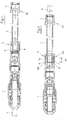
- Both the male part 8 of the coupling device 4 as well as the connection part 18 and ultimately also the union nut 9 have an additional security piece 10, 11, so that a total of an extended security shaft 40 is realized.
- This safety shaft 40 has an annular surface 39, which is practically a first sealing zone.
- the outer surface of the security piece 10 and the male part 8 are designated by the reference numeral 12 as a sealing surface, as well as the inner surface of the connecting part 18 of the lance holder 2 by the reference numeral 13. Lying these Sealing surfaces 12, 13 as in FIG. 4 shown to one another, this results in an advantageous long sealing zone.
- the counter-connection piece 35 of the safety tube 3 is formed as the opposite end of the lance holder 2, namely as the connecting part 18.
- an annular web 37 is formed, which serves as a stop for the inserted or inserted Plug-in part 8 of the safety tube 3 but also serves as a sealing zone, because here on the nut 9, a correspondingly high contact pressure can be generated.
- the extended union nut 9 corresponds with its internal thread 21 with the external thread 20 of the lance holder 2 or its connection part 18, which is in particular also FIG. 3 can take. External thread 20 and internal thread 21 result in the thread 14, over which the union nut 9 can be moved along a total of about fifteen threads 41, 42 on the connection part 18 in order to realize the individual sealing zones.
- the sealing surface 25 is activated and that at the free end 26 of the connecting part 18, which corresponds here with the support ring 22 and the inner surface 23, so that thus the mentioned sealing zone can be realized.
- FIG. 1 shows the not yet closed and FIG. 2 the closed coupling device 4.
- the essential seal is achieved via the ring seal 15 at the free end 26 of the female part 19 formed as a connecting part 18.
- this annular seal 15 is realized by two spaced annular grooves 28, 30 with O-rings 29, 31, wherein these two O-rings 29, 31 each form an optimum sealing zone.
- the main sealing effect remains even if the nut 9 is not properly tightened or has loosened, so that the male part 8 has pulled out of the female part 19 by a certain amount.
- the covered by the O-rings sealing surface area 33 at the male part 8 at about 33 to 50% of the sealing surface area 32 makes up, the only of the female part 19 or plug-in part 8 are formed.
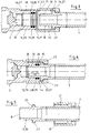
- FIG. 4 clarified, in which case the extended security pieces are provided with the reference numerals 10, 11 and 14 '.
- the security piece 10 belongs to the male part 8, the security piece 11 to the union nut 9 and the security piece 14 'to the connection part 18th
- FIG. 5 makes clear that the union nut 9 is easy to move. It is shown pushed back here very far to show the male part 8 at the front end of the safety tube 3. It is formed elongated, has an acting as a sealing surface 12 annular surface 39 and provides the aforementioned multiple safety both in terms of the seal as well as in terms of stability (kink protection). All this is also of great importance, because even with the valve closed in the lance holder 2 in this area highly flammable gas is pending at high pressure.
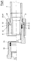
- FIG. 6 Finally, the additional sealing zone in the region of the inside of the support ring 22.
- the inside of the support ring 22 forms a slope 49 and that one of the surface bottom 48 to the outer edge 52 of the support ring 22nd leading slope 49.
- This the sealing surface 25 forming slope 49 is broken off just before the outer edge 52, so that a sealing edge 50 is formed. Since the slope 49 is at an angle of ⁇ 5 ° to the vertical, the sealing edge 50 acts in the sealing of the two metal parts advantageously supporting.
- a sealing zone is realized where the male part 8 abuts against the annular web 37.
- the second sealing zone and the third sealing zone are in the region of the O-rings 29 and 31, which is retained even when pulling out the male part 8, so that a multiple fuse is achieved.
- the fourth Sealing zone is realized when pressing the support ring 22 to the front edge of the connecting part 18 and nut member 19, while the fifth sealing zone of the two sealing surfaces 12, 13 and ring surface 39 is formed.
Priority Applications (1)
| Application Number | Priority Date | Filing Date | Title |
|---|---|---|---|
| PL11817466T PL2659009T3 (pl) | 2010-12-28 | 2011-12-15 | Wielokrotnie zabezpieczony mechanizm sprzęgający do lanc tlenowych |
Applications Claiming Priority (3)
| Application Number | Priority Date | Filing Date | Title |
|---|---|---|---|
| DE102010056153 | 2010-12-28 | ||
| DE102011014323A DE102011014323A1 (de) | 2010-12-28 | 2011-03-18 | Mehrfach gesicherte Koppelvorrichtung für Sauerstofflanzen |
| PCT/DE2011/002127 WO2012089188A2 (de) | 2010-12-28 | 2011-12-15 | Mehrfach gesicherte koppelvorrichtung für sauerstofflanzen |
Publications (2)
| Publication Number | Publication Date |
|---|---|
| EP2659009A2 EP2659009A2 (de) | 2013-11-06 |
| EP2659009B1 true EP2659009B1 (de) | 2018-02-28 |
Family
ID=45592110
Family Applications (1)
| Application Number | Title | Priority Date | Filing Date |
|---|---|---|---|
| EP11817466.3A Active EP2659009B1 (de) | 2010-12-28 | 2011-12-15 | Mehrfach gesicherte koppelvorrichtung für sauerstofflanzen |
Country Status (13)
| Country | Link |
|---|---|
| US (1) | US9500306B2 (tr) |
| EP (1) | EP2659009B1 (tr) |
| JP (1) | JP6084166B2 (tr) |
| KR (1) | KR101805963B1 (tr) |
| CN (1) | CN103429763B (tr) |
| BR (1) | BR112013016111B1 (tr) |
| DE (1) | DE102011014323A1 (tr) |
| ES (1) | ES2663599T3 (tr) |
| PL (1) | PL2659009T3 (tr) |
| PT (1) | PT2659009T (tr) |
| TR (1) | TR201806980T4 (tr) |
| TW (1) | TWI575073B (tr) |
| WO (1) | WO2012089188A2 (tr) |
Families Citing this family (4)
| Publication number | Priority date | Publication date | Assignee | Title |
|---|---|---|---|---|
| US9572171B2 (en) * | 2013-10-31 | 2017-02-14 | Intel IP Corporation | Systems, methods, and devices for efficient device-to-device channel contention |
| CN104989891B (zh) * | 2015-07-10 | 2018-08-21 | 秦皇岛北方管业有限公司 | 一种长寿命防泄漏氧枪冷却水金属软管 |
| US10888886B2 (en) * | 2017-12-19 | 2021-01-12 | Raytheon Technologies Corporation | Modular cold-spray receiver |
| KR102176953B1 (ko) * | 2020-07-28 | 2020-11-10 | 주식회사 비비씨 | 랜스 파이프용 고정홀더 |
Family Cites Families (38)
| Publication number | Priority date | Publication date | Assignee | Title |
|---|---|---|---|---|
| US2829673A (en) * | 1954-08-24 | 1958-04-08 | Ind Instr Corp | Pipe unions |
| US3202442A (en) * | 1961-05-19 | 1965-08-24 | Aeroquip Corp | Coupling |
| US3201148A (en) * | 1963-05-16 | 1965-08-17 | Chatleff Controls Inc | Coupling means for connecting conduits |
| US3476414A (en) * | 1966-11-30 | 1969-11-04 | United States Steel Corp | Pipe joint |
| US3533649A (en) * | 1969-01-30 | 1970-10-13 | Genova Products | Pipe fitting |
| US3900223A (en) * | 1974-01-23 | 1975-08-19 | Sundstrand Corp | Pipe coupling |
| DE2650370C2 (de) * | 1975-11-12 | 1986-12-04 | Kjell Ronny Zug Ekman | Verriegelbare Leitungskupplung |
| SE444712B (sv) * | 1980-06-06 | 1986-04-28 | Ekman K R | Kopplingsanordning med han- och hondelar och dessa tilldelade lasorgan |
| US4555129A (en) * | 1980-12-09 | 1985-11-26 | Davlin Irwin H | Adapter union and improved adapter member therefor |
| JPS58132335U (ja) * | 1982-02-26 | 1983-09-06 | テイサン株式会社 | 自動着火式切断用ト−チ |
| US4801160A (en) * | 1981-09-17 | 1989-01-31 | Michael J. Caddell | High-pressure fluid flow connector |
| JPS619972A (ja) * | 1984-06-26 | 1986-01-17 | Fuaiaaransu Kogyo Kk | ランス用管体の着脱方法及びその着脱確認装置 |
| JPS6246190U (tr) * | 1985-09-03 | 1987-03-20 | ||
| US5678607A (en) * | 1986-01-15 | 1997-10-21 | Krywitsky; Lee A. | Reusable pipe union and pipe cap assembly for wide thermal cycling |
| US4750765A (en) * | 1987-07-27 | 1988-06-14 | Stratoflex, Inc. | Quick-connect coupling |
| JPH01159513A (ja) * | 1987-12-15 | 1989-06-22 | Tanaka Seisakusho:Kk | 切断火口 |
| DE3880841D1 (de) | 1988-12-02 | 1993-06-09 | Beda Oxygentech Armatur | Kompaktlanze mit rohrverdrehsicherung. |
| US5060988A (en) * | 1990-05-08 | 1991-10-29 | Nwd International, Inc. | Hydraulic coupling |
| LU87761A1 (fr) * | 1990-07-04 | 1992-03-11 | Wurth Paul Sa | Dispositif d'accouplement automatique d'une lance d'insufflation a une tete de raccord |
| US5110160A (en) * | 1990-08-23 | 1992-05-05 | Fluid Line Products, Inc. | High pressure port fitting system |
| JPH11257570A (ja) * | 1998-03-11 | 1999-09-21 | Nippon Grease Nipple Kk | 高温流体を通すフッ素樹脂製管状部材用のフッ素樹脂製継手 |
| NO310372B1 (no) * | 1999-08-02 | 2001-06-25 | Bakke Technology As | Delt koplingsanordning med gjennomgående boring |
| JP2001159495A (ja) * | 1999-12-03 | 2001-06-12 | San-Ei Faucet Mfg Co Ltd | 配管用ヘッダー |
| JP2002022074A (ja) * | 2000-07-06 | 2002-01-23 | Zexel Valeo Climate Control Corp | 管継手 |
| US6481761B2 (en) * | 2001-02-21 | 2002-11-19 | Visteon Global Technologies, Inc. | Frusto-conical seal fitting |
| WO2003056227A1 (en) * | 2001-12-25 | 2003-07-10 | Mirai Industry Co., Ltd. | End part structure of water passing tube, water passing tube with the end part structure, structure of connection between water passing tube and connection body, and method of forming end part structure of water passing tube |
| US7077436B1 (en) * | 2002-05-06 | 2006-07-18 | Hilltap Fittings, Ltd. | Gear operated coupler |
| US7032677B2 (en) * | 2003-06-27 | 2006-04-25 | H W Ces International | Multi-lock adapters for independent screwed wellheads and methods of using same |
| US7159652B2 (en) * | 2003-09-04 | 2007-01-09 | Oil States Energy Services, Inc. | Drilling flange and independent screwed wellhead with metal-to-metal seal and method of use |
| KR100497010B1 (ko) * | 2005-03-15 | 2005-06-27 | (주) 영진산기 | 래들에 남아있는 지금을 제거하기 위한 산소홀더 |
| US7690693B2 (en) * | 2005-08-04 | 2010-04-06 | Parker-Hannifin Corporation | Pre-assemblable, push-in fitting connection for corrugated tubing |
| JP4456567B2 (ja) * | 2006-02-01 | 2010-04-28 | 東尾メック株式会社 | 管継手 |
| EP2162662B9 (de) * | 2007-06-18 | 2012-08-22 | Weidmann LTD. | Verbindungsanordnung für eine rohrverschraubung |
| JP5311795B2 (ja) * | 2007-10-25 | 2013-10-09 | 旭有機材工業株式会社 | 管継手 |
| DE102008012554B4 (de) * | 2008-03-04 | 2011-12-22 | Beda Oxygentechnik Armaturen Gmbh | Lanzenhalter |
| CN201259046Y (zh) * | 2008-07-28 | 2009-06-17 | 简明锐 | 一种连接接头 |
| JP2010065386A (ja) * | 2008-09-08 | 2010-03-25 | Amagasaki Juki Kk | 油圧配管連結装置 |
| DE102009005940B3 (de) * | 2009-01-23 | 2010-07-08 | Henco Industries Nv | Montagesystem eines Fittings mit einem Rohr und einem Montagekörper |
-
2011
- 2011-03-18 DE DE102011014323A patent/DE102011014323A1/de not_active Withdrawn
- 2011-10-21 TW TW100138193A patent/TWI575073B/zh active
- 2011-12-15 EP EP11817466.3A patent/EP2659009B1/de active Active
- 2011-12-15 WO PCT/DE2011/002127 patent/WO2012089188A2/de active Application Filing
- 2011-12-15 US US13/977,085 patent/US9500306B2/en active Active
- 2011-12-15 KR KR1020137016392A patent/KR101805963B1/ko active IP Right Grant
- 2011-12-15 TR TR2018/06980T patent/TR201806980T4/tr unknown
- 2011-12-15 JP JP2013546587A patent/JP6084166B2/ja active Active
- 2011-12-15 PT PT118174663T patent/PT2659009T/pt unknown
- 2011-12-15 PL PL11817466T patent/PL2659009T3/pl unknown
- 2011-12-15 CN CN201180063516.5A patent/CN103429763B/zh active Active
- 2011-12-15 ES ES11817466.3T patent/ES2663599T3/es active Active
- 2011-12-15 BR BR112013016111-6A patent/BR112013016111B1/pt active IP Right Grant
Also Published As
| Publication number | Publication date |
|---|---|
| KR20130135874A (ko) | 2013-12-11 |
| ES2663599T3 (es) | 2018-04-16 |
| TR201806980T4 (tr) | 2018-06-21 |
| PT2659009T (pt) | 2018-04-03 |
| CN103429763B (zh) | 2016-02-03 |
| EP2659009A2 (de) | 2013-11-06 |
| WO2012089188A2 (de) | 2012-07-05 |
| JP2014509371A (ja) | 2014-04-17 |
| BR112013016111B1 (pt) | 2019-05-28 |
| TW201226574A (en) | 2012-07-01 |
| TWI575073B (zh) | 2017-03-21 |
| PL2659009T3 (pl) | 2018-08-31 |
| JP6084166B2 (ja) | 2017-02-22 |
| BR112013016111A2 (pt) | 2018-07-10 |
| US9500306B2 (en) | 2016-11-22 |
| US20130285373A1 (en) | 2013-10-31 |
| CN103429763A (zh) | 2013-12-04 |
| WO2012089188A3 (de) | 2012-11-01 |
| KR101805963B1 (ko) | 2017-12-06 |
| DE102011014323A1 (de) | 2012-06-28 |
Similar Documents
| Publication | Publication Date | Title |
|---|---|---|
| EP0207339A1 (de) | Verbindungsanordnung mit einer Schraubmuffe | |
| EP2659009B1 (de) | Mehrfach gesicherte koppelvorrichtung für sauerstofflanzen | |
| EP2192338A2 (de) | Anschlussstück | |
| DD207748A5 (de) | Dichtung fuer stahlrohre, insbesondere aus stahl oder legierungen | |
| DE102013109123A1 (de) | Verbindung zwischen einem Verbindungsteil, einem Rohrteil und einem Hülsenteil, Verfahren zur Verbindung zwischen einem Verbindungsteil, einem Rohrteil und einem Hülsenteil, Einführteil zum Einführen eines Rohrendes und kreisringförmiges Rückzug-Sperrteil | |
| DE808173C (de) | Rohr- und Schlauchkupplung | |
| DE2934491C2 (de) | Mauerdurchführung | |
| DE102017207053B4 (de) | Abgasrohr sowie Verfahren zum Ablängen eines Abgasrohres | |
| DE669605C (de) | Rohrverbindung zum elastischen Kuppeln eines glatten Rohrendes, insbesondere eines Asbestzementrohres, mit einem einen Flansch aufweisenden Anschlussstueck | |
| DE19818571C2 (de) | Rohrverschraubung zur mediendichten Verbindung von Rohrendstücken | |
| DE102008062823B3 (de) | Klemmverschraubung zum Befestigen von länglichen Körpern oder Rohren | |
| DE1911064A1 (de) | Selbstblockierende Rohrverbindung | |
| DE102007036504B4 (de) | Anordnung aus einem rohrförmigen Bauteil und einem Anschlussstück | |
| DE3731222C2 (tr) | ||
| DE2512016C2 (de) | Heizkörperverschraubung | |
| DE202006017177U1 (de) | Fluidleitungsverbindungsanordnung | |
| DE19731565C1 (de) | Rohrverschraubung | |
| WO2010139512A1 (de) | Verschluss, stahlhülse und vorrichtung zur kalibrierung des koenen-tests | |
| DE102007007780C5 (de) | Richtungseinstellbare Rohrverschraubung | |
| DE202007000951U1 (de) | Einwandiges röhrenförmiges Element für Rauchzüge, das mit Schnellverschlussmitteln ausgestattet ist | |
| DE3636082C2 (de) | Gas-Hausanschlußvorrichtung | |
| DE3404632A1 (de) | Schnellverbindung fuer rohre | |
| DE4107048A1 (de) | Verbindung eines mit einem aussenprofil versehenen, rohrfoermigen anschlussstutzens mit einem anschlussstueck, verfahren sowie zwischenstueck und anschlussstueck zur herstellung der verbindung und verwendung der verbindung | |
| EP2774670A1 (de) | Reaktor | |
| DE102011017315B4 (de) | Steckkupplung für medienführende Leitungen mit zwei unter beengten Bedingungen verbindbaren Kupplungselementen |
Legal Events
| Date | Code | Title | Description |
|---|---|---|---|
| PUAI | Public reference made under article 153(3) epc to a published international application that has entered the european phase |
Free format text: ORIGINAL CODE: 0009012 |
|
| 17P | Request for examination filed |
Effective date: 20130729 |
|
| AK | Designated contracting states |
Kind code of ref document: A2 Designated state(s): AL AT BE BG CH CY CZ DE DK EE ES FI FR GB GR HR HU IE IS IT LI LT LU LV MC MK MT NL NO PL PT RO RS SE SI SK SM TR |
|
| DAX | Request for extension of the european patent (deleted) | ||
| 17Q | First examination report despatched |
Effective date: 20161107 |
|
| GRAP | Despatch of communication of intention to grant a patent |
Free format text: ORIGINAL CODE: EPIDOSNIGR1 |
|
| RIC1 | Information provided on ipc code assigned before grant |
Ipc: C21C 5/46 20060101AFI20170928BHEP Ipc: F16L 19/02 20060101ALI20170928BHEP |
|
| INTG | Intention to grant announced |
Effective date: 20171017 |
|
| GRAS | Grant fee paid |
Free format text: ORIGINAL CODE: EPIDOSNIGR3 |
|
| GRAA | (expected) grant |
Free format text: ORIGINAL CODE: 0009210 |
|
| AK | Designated contracting states |
Kind code of ref document: B1 Designated state(s): AL AT BE BG CH CY CZ DE DK EE ES FI FR GB GR HR HU IE IS IT LI LT LU LV MC MK MT NL NO PL PT RO RS SE SI SK SM TR |
|
| REG | Reference to a national code |
Ref country code: GB Ref legal event code: FG4D Free format text: NOT ENGLISH Ref country code: CH Ref legal event code: EP |
|
| REG | Reference to a national code |
Ref country code: AT Ref legal event code: REF Ref document number: 974194 Country of ref document: AT Kind code of ref document: T Effective date: 20180315 |
|
| REG | Reference to a national code |
Ref country code: IE Ref legal event code: FG4D Free format text: LANGUAGE OF EP DOCUMENT: GERMAN |
|
| REG | Reference to a national code |
Ref country code: DE Ref legal event code: R096 Ref document number: 502011013838 Country of ref document: DE Ref country code: CH Ref legal event code: NV Representative=s name: FELBER UND PARTNER AG, CH |
|
| REG | Reference to a national code |
Ref country code: PT Ref legal event code: SC4A Ref document number: 2659009 Country of ref document: PT Date of ref document: 20180403 Kind code of ref document: T Free format text: AVAILABILITY OF NATIONAL TRANSLATION Effective date: 20180327 |
|
| REG | Reference to a national code |
Ref country code: RO Ref legal event code: EPE Ref country code: ES Ref legal event code: FG2A Ref document number: 2663599 Country of ref document: ES Kind code of ref document: T3 Effective date: 20180416 |
|
| REG | Reference to a national code |
Ref country code: NL Ref legal event code: FP |
|
| REG | Reference to a national code |
Ref country code: SE Ref legal event code: TRGR |
|
| REG | Reference to a national code |
Ref country code: NO Ref legal event code: T2 Effective date: 20180228 |
|
| REG | Reference to a national code |
Ref country code: LT Ref legal event code: MG4D |
|
| PG25 | Lapsed in a contracting state [announced via postgrant information from national office to epo] |
Ref country code: CY Free format text: LAPSE BECAUSE OF FAILURE TO SUBMIT A TRANSLATION OF THE DESCRIPTION OR TO PAY THE FEE WITHIN THE PRESCRIBED TIME-LIMIT Effective date: 20180228 Ref country code: LT Free format text: LAPSE BECAUSE OF FAILURE TO SUBMIT A TRANSLATION OF THE DESCRIPTION OR TO PAY THE FEE WITHIN THE PRESCRIBED TIME-LIMIT Effective date: 20180228 Ref country code: HR Free format text: LAPSE BECAUSE OF FAILURE TO SUBMIT A TRANSLATION OF THE DESCRIPTION OR TO PAY THE FEE WITHIN THE PRESCRIBED TIME-LIMIT Effective date: 20180228 |
|
| PG25 | Lapsed in a contracting state [announced via postgrant information from national office to epo] |
Ref country code: LV Free format text: LAPSE BECAUSE OF FAILURE TO SUBMIT A TRANSLATION OF THE DESCRIPTION OR TO PAY THE FEE WITHIN THE PRESCRIBED TIME-LIMIT Effective date: 20180228 Ref country code: BG Free format text: LAPSE BECAUSE OF FAILURE TO SUBMIT A TRANSLATION OF THE DESCRIPTION OR TO PAY THE FEE WITHIN THE PRESCRIBED TIME-LIMIT Effective date: 20180528 Ref country code: RS Free format text: LAPSE BECAUSE OF FAILURE TO SUBMIT A TRANSLATION OF THE DESCRIPTION OR TO PAY THE FEE WITHIN THE PRESCRIBED TIME-LIMIT Effective date: 20180228 |
|
| REG | Reference to a national code |
Ref country code: GR Ref legal event code: EP Ref document number: 20180400954 Country of ref document: GR Effective date: 20180829 |
|
| PG25 | Lapsed in a contracting state [announced via postgrant information from national office to epo] |
Ref country code: MT Free format text: LAPSE BECAUSE OF FAILURE TO SUBMIT A TRANSLATION OF THE DESCRIPTION OR TO PAY THE FEE WITHIN THE PRESCRIBED TIME-LIMIT Effective date: 20180228 |
|
| PG25 | Lapsed in a contracting state [announced via postgrant information from national office to epo] |
Ref country code: AL Free format text: LAPSE BECAUSE OF FAILURE TO SUBMIT A TRANSLATION OF THE DESCRIPTION OR TO PAY THE FEE WITHIN THE PRESCRIBED TIME-LIMIT Effective date: 20180228 Ref country code: EE Free format text: LAPSE BECAUSE OF FAILURE TO SUBMIT A TRANSLATION OF THE DESCRIPTION OR TO PAY THE FEE WITHIN THE PRESCRIBED TIME-LIMIT Effective date: 20180228 |
|
| REG | Reference to a national code |
Ref country code: DE Ref legal event code: R097 Ref document number: 502011013838 Country of ref document: DE |
|
| PG25 | Lapsed in a contracting state [announced via postgrant information from national office to epo] |
Ref country code: SM Free format text: LAPSE BECAUSE OF FAILURE TO SUBMIT A TRANSLATION OF THE DESCRIPTION OR TO PAY THE FEE WITHIN THE PRESCRIBED TIME-LIMIT Effective date: 20180228 Ref country code: DK Free format text: LAPSE BECAUSE OF FAILURE TO SUBMIT A TRANSLATION OF THE DESCRIPTION OR TO PAY THE FEE WITHIN THE PRESCRIBED TIME-LIMIT Effective date: 20180228 |
|
| PLBE | No opposition filed within time limit |
Free format text: ORIGINAL CODE: 0009261 |
|
| STAA | Information on the status of an ep patent application or granted ep patent |
Free format text: STATUS: NO OPPOSITION FILED WITHIN TIME LIMIT |
|
| 26N | No opposition filed |
Effective date: 20181129 |
|
| PG25 | Lapsed in a contracting state [announced via postgrant information from national office to epo] |
Ref country code: SI Free format text: LAPSE BECAUSE OF FAILURE TO SUBMIT A TRANSLATION OF THE DESCRIPTION OR TO PAY THE FEE WITHIN THE PRESCRIBED TIME-LIMIT Effective date: 20180228 |
|
| PG25 | Lapsed in a contracting state [announced via postgrant information from national office to epo] |
Ref country code: MC Free format text: LAPSE BECAUSE OF FAILURE TO SUBMIT A TRANSLATION OF THE DESCRIPTION OR TO PAY THE FEE WITHIN THE PRESCRIBED TIME-LIMIT Effective date: 20180228 |
|
| REG | Reference to a national code |
Ref country code: IE Ref legal event code: MM4A |
|
| PG25 | Lapsed in a contracting state [announced via postgrant information from national office to epo] |
Ref country code: IE Free format text: LAPSE BECAUSE OF NON-PAYMENT OF DUE FEES Effective date: 20181215 |
|
| PG25 | Lapsed in a contracting state [announced via postgrant information from national office to epo] |
Ref country code: MK Free format text: LAPSE BECAUSE OF NON-PAYMENT OF DUE FEES Effective date: 20180228 Ref country code: HU Free format text: LAPSE BECAUSE OF FAILURE TO SUBMIT A TRANSLATION OF THE DESCRIPTION OR TO PAY THE FEE WITHIN THE PRESCRIBED TIME-LIMIT; INVALID AB INITIO Effective date: 20111215 |
|
| PG25 | Lapsed in a contracting state [announced via postgrant information from national office to epo] |
Ref country code: IS Free format text: LAPSE BECAUSE OF FAILURE TO SUBMIT A TRANSLATION OF THE DESCRIPTION OR TO PAY THE FEE WITHIN THE PRESCRIBED TIME-LIMIT Effective date: 20180628 |
|
| PGFP | Annual fee paid to national office [announced via postgrant information from national office to epo] |
Ref country code: ES Payment date: 20230118 Year of fee payment: 12 Ref country code: CH Payment date: 20221228 Year of fee payment: 12 |
|
| PGFP | Annual fee paid to national office [announced via postgrant information from national office to epo] |
Ref country code: SK Payment date: 20231127 Year of fee payment: 13 |
|
| PGFP | Annual fee paid to national office [announced via postgrant information from national office to epo] |
Ref country code: GR Payment date: 20231220 Year of fee payment: 13 Ref country code: GB Payment date: 20231219 Year of fee payment: 13 |
|
| PGFP | Annual fee paid to national office [announced via postgrant information from national office to epo] |
Ref country code: TR Payment date: 20231127 Year of fee payment: 13 Ref country code: SE Payment date: 20231222 Year of fee payment: 13 Ref country code: RO Payment date: 20231128 Year of fee payment: 13 Ref country code: PT Payment date: 20231124 Year of fee payment: 13 Ref country code: NO Payment date: 20231219 Year of fee payment: 13 Ref country code: NL Payment date: 20231226 Year of fee payment: 13 Ref country code: LU Payment date: 20231226 Year of fee payment: 13 Ref country code: IT Payment date: 20231221 Year of fee payment: 13 Ref country code: FR Payment date: 20231226 Year of fee payment: 13 Ref country code: FI Payment date: 20231228 Year of fee payment: 13 Ref country code: DE Payment date: 20231215 Year of fee payment: 13 Ref country code: CZ Payment date: 20231128 Year of fee payment: 13 Ref country code: AT Payment date: 20231219 Year of fee payment: 13 |
|
| PGFP | Annual fee paid to national office [announced via postgrant information from national office to epo] |
Ref country code: PL Payment date: 20231121 Year of fee payment: 13 Ref country code: BE Payment date: 20231226 Year of fee payment: 13 |
|
| PGFP | Annual fee paid to national office [announced via postgrant information from national office to epo] |
Ref country code: ES Payment date: 20240118 Year of fee payment: 13 |
|
| PGFP | Annual fee paid to national office [announced via postgrant information from national office to epo] |
Ref country code: CH Payment date: 20240102 Year of fee payment: 13 |