EP2659009B1 - Mehrfach gesicherte koppelvorrichtung für sauerstofflanzen - Google Patents
Mehrfach gesicherte koppelvorrichtung für sauerstofflanzen Download PDFInfo
- Publication number
- EP2659009B1 EP2659009B1 EP11817466.3A EP11817466A EP2659009B1 EP 2659009 B1 EP2659009 B1 EP 2659009B1 EP 11817466 A EP11817466 A EP 11817466A EP 2659009 B1 EP2659009 B1 EP 2659009B1
- Authority
- EP
- European Patent Office
- Prior art keywords
- coupling device
- accordance
- sealing
- connecting part
- plug
- Prior art date
- Legal status (The legal status is an assumption and is not a legal conclusion. Google has not performed a legal analysis and makes no representation as to the accuracy of the status listed.)
- Active
Links
- 230000008878 coupling Effects 0.000 title claims description 40
- 238000010168 coupling process Methods 0.000 title claims description 40
- 238000005859 coupling reaction Methods 0.000 title claims description 40
- 239000001301 oxygen Substances 0.000 title claims description 14
- 229910052760 oxygen Inorganic materials 0.000 title claims description 14
- QVGXLLKOCUKJST-UHFFFAOYSA-N atomic oxygen Chemical compound [O] QVGXLLKOCUKJST-UHFFFAOYSA-N 0.000 title claims description 13
- 238000007789 sealing Methods 0.000 claims description 78
- 239000007789 gas Substances 0.000 claims description 10
- 230000000694 effects Effects 0.000 claims description 7
- 229910001220 stainless steel Inorganic materials 0.000 claims description 4
- 239000010935 stainless steel Substances 0.000 claims description 4
- 229910001369 Brass Inorganic materials 0.000 claims description 2
- 239000010951 brass Substances 0.000 claims description 2
- 239000000161 steel melt Substances 0.000 claims 1
- 239000002184 metal Substances 0.000 description 5
- 229910000831 Steel Inorganic materials 0.000 description 3
- 239000010959 steel Substances 0.000 description 3
- 230000009286 beneficial effect Effects 0.000 description 1
- 239000002737 fuel gas Substances 0.000 description 1
- 238000003780 insertion Methods 0.000 description 1
- 230000037431 insertion Effects 0.000 description 1
- 230000013011 mating Effects 0.000 description 1
- 238000003032 molecular docking Methods 0.000 description 1
- 150000002926 oxygen Chemical class 0.000 description 1
- 230000000717 retained effect Effects 0.000 description 1
- 238000000926 separation method Methods 0.000 description 1
Images
Classifications
-
- F—MECHANICAL ENGINEERING; LIGHTING; HEATING; WEAPONS; BLASTING
- F16—ENGINEERING ELEMENTS AND UNITS; GENERAL MEASURES FOR PRODUCING AND MAINTAINING EFFECTIVE FUNCTIONING OF MACHINES OR INSTALLATIONS; THERMAL INSULATION IN GENERAL
- F16L—PIPES; JOINTS OR FITTINGS FOR PIPES; SUPPORTS FOR PIPES, CABLES OR PROTECTIVE TUBING; MEANS FOR THERMAL INSULATION IN GENERAL
- F16L19/00—Joints in which sealing surfaces are pressed together by means of a member, e.g. a swivel nut, screwed on or into one of the joint parts
- F16L19/02—Pipe ends provided with collars or flanges, integral with the pipe or not, pressed together by a screwed member
-
- C—CHEMISTRY; METALLURGY
- C21—METALLURGY OF IRON
- C21C—PROCESSING OF PIG-IRON, e.g. REFINING, MANUFACTURE OF WROUGHT-IRON OR STEEL; TREATMENT IN MOLTEN STATE OF FERROUS ALLOYS
- C21C5/00—Manufacture of carbon-steel, e.g. plain mild steel, medium carbon steel or cast steel or stainless steel
- C21C5/28—Manufacture of steel in the converter
- C21C5/42—Constructional features of converters
- C21C5/46—Details or accessories
- C21C5/4606—Lances or injectors
- C21C5/462—Means for handling, e.g. adjusting, changing, coupling
-
- F—MECHANICAL ENGINEERING; LIGHTING; HEATING; WEAPONS; BLASTING
- F16—ENGINEERING ELEMENTS AND UNITS; GENERAL MEASURES FOR PRODUCING AND MAINTAINING EFFECTIVE FUNCTIONING OF MACHINES OR INSTALLATIONS; THERMAL INSULATION IN GENERAL
- F16L—PIPES; JOINTS OR FITTINGS FOR PIPES; SUPPORTS FOR PIPES, CABLES OR PROTECTIVE TUBING; MEANS FOR THERMAL INSULATION IN GENERAL
- F16L19/00—Joints in which sealing surfaces are pressed together by means of a member, e.g. a swivel nut, screwed on or into one of the joint parts
- F16L19/02—Pipe ends provided with collars or flanges, integral with the pipe or not, pressed together by a screwed member
- F16L19/025—Pipe ends provided with collars or flanges, integral with the pipe or not, pressed together by a screwed member the pipe ends having integral collars or flanges
Definitions
- the invention relates to a multiply secured coupling device for oxygen lances and other, flammable gases leading and injecting these media in the molten steel tubes, which have a designed as a valve lance holder and a safety tube, which is arranged between the lance holder and a lance tube leading to the supplier or directly connected to the supplier.
- a burner tube holder or an oxygen lance with lance holder is for example from EP 0 372 099 B1 known. At the oxygen inlet of this lance holder, however, only a thread is indicated, on which a safety tube, not shown here, is screwed.
- a safety tube not shown here.
- Such usually made of stainless steel safety pipes or safety routes are helpful in manually operated lance holders and serve above all to increase the reliability, because it is to be achieved through the proper management of flammable gases especially the oxygen to the lance holder. It is difficult, however, if traded carelessly in the coupling device between the oxygen lance and the safety route or the safety tube and the coupling device is not tightened enough, because then the leakage of highly flammable gas can still occur.
- the coupling device is always tightened to ensure the tightness of the connection. In case of carelessness, however, the described hazard is still present.
- the sealing ring is assigned to the male part and has an oblique sealing surface.
- the JP 58 132335 includes a burner having supply channels for oxygen and fuel gas.
- the EP 1 159 513 A concerns such a burner.
- the DE 10 2009 005 940 B3 becomes taught a mounting system in which components are connected via a union nut.
- the DE 10 2008 012 534 A1 has a lance holder to the object, which can be connected to a lance tube or a safety tube.
- the invention is therefore an object of the invention to provide a coupling device for oxygen supply lines in steel mills, in which dangerous leaks are approximately avoided, if possible even completely excluded.
- the safety tube has an insertable into the connection part of the lance holder male part which forms the coupling device with a screw on the lance holder union coupling and as well as connector and union nut is extended by a security piece that a wide insertion in the connection part permitting and thus a sealing effect even with loose seated union nut guaranteed formed and equipped with at least one against the connection part of the lance holder in the region of sealing surfaces sealing, the free end of the connecting part associated ring seal and on the other hand an elongated thread which is associated with the ring seal Sealing surface area of the sealing surface on the extended plug-in part makes up 33-50% of the sealing surface area, which is formed only by the connecting part and plug-in part.
- Connecting part, union nut and plug-in part are formed extended by a security piece, wherein the ring seal associated sealing surface area is significantly shorter than the only formed by the connecting part and plug-in sealing surface area, so it is clear which dimensioning of the security piece in all three components has to be expediently
- a trained coupling device between oxygen lance and safety tube is also the necessary security guaranteed if the nut is not one hundred percent tightened.
- both the connection part and the union nut as well as the plug-in part are extended once to an additional sealing zone create and on the other hand in order to ensure the necessary tightness of the system in the loose arrangement of the union nut nevertheless by the extended plug-in part and the suitably mounted ring seal.
- the ring seal is arranged so that the plug-in part can be inserted far into the connection part of the lance holder and the ring seal is arranged only at the free end of the connection part.
- the ring seal is thus still effective even if the male part is pulled out of the male part by a certain range by a loose union nut.
- the ring seal is formed by two arranged in spaced annular grooves O-rings wherein the male part has over the O-rings of the ring seal projecting free sealing surface area, which is twice as large as that of the two O-rings Covered sealing surface area.
- connection part of the lance holder serves as an extended female part and is designed to have frictional annular seal on the correspondingly extended and serving as a male part male part of the safety tube or lance tube.
- the male part of the safety tube serving as a plug part is associated with a corresponding with the external thread of the connecting part internal thread. Since both threaded areas are the same length and the same shape, the necessary secure connection between the safety tube and lance holder can be ensured with the appropriate union nut.
- the invention provides for this purpose that the male part has a support ring, against the inner surface formed as a sealing surface, the free end of the connecting part of the lance holder can be pressed via the sliding on the external thread union nut.
- the ring seal is thus arranged in the connection part of the lance holder in the extended nut part, that a sealing effect is still present even if the plug-in part is slightly pulled out of the connection part with loose-fitting cap nut. As defined in claim 1, this is ensured by the fact that the ring seal is assigned to the free end of the connecting part and as far as possible at the free end, so as to maintain the said securing the connection as long as possible.
- the lance tube is connected to the safety tube.
- the safety tube has a counterpart connection part designed in accordance with the connection part of the lance holder.
- the lance tube receives accordingly a male part, which corresponds to the male part of the safety tube, so that thus an equally advantageous connection is possible, as with the lance holder.
- the present invention receives the fact that in the deepest part of the connecting part of the lance holder at the same time serving as a stop for the male part ring web is formed. This can be sealed by acting on the union nut at the same time lying in the lowest sealing zone and in the region of the support ring, so that together with the ring seal virtually four sealing zones are present, which are beneficial for the advantageous sealing effect of the coupling device.
- the nut itself is also designed to be extended, as the male part and the connector, which is provided according to an advantageous embodiment that the nut is formed having ten to twenty threads, while conventional union nuts have only five to seven threads. This makes it clear that even over the longer thread additional security is given, since even with a slightly loosened union nut still sufficient thread is present to exclude a separation and thus a complete leak.
- a durable easy production of the connection between the lance holder and safety tube on the coupling device is given in particular, if the union nut made of brass and the male part as well as the rest of the safety tube are made of stainless steel.
- the union nut of the less hard metal can thus be easily screwed onto the likewise made of stainless steel connecting part of the lance holder.
- Another sealing zone is created between the support ring and the free end of the connection part and without a separate sealing ring.
- the existing on the support ring sealing surface on the support ring is formed dense metal, so that metal is metal.
- This advantageous seal achieves the invention primarily by the fact that the sealing surface is inclined starting from the surface base outwards and thereby has an inclination of preferably 5 °. Finally, in this slope, a sealing edge created by aborting the slope, so that a particularly intense seal is created, which acts as a further sealing zone.
- the invention is characterized in particular by the fact that a multiply secured coupling device between the lance holder and the subsequent lance tube is provided, which is of considerable advantage if a safety tube or a safety distance is provided between the lance holder and the lance tube.
- This safety tube has on both sides an overall length increasing safety piece with sealing surface or thread, so that when the safety tube and the connection piece of the lance holder are guided into each other, a complete sealing of this coupling device is achieved.
- the necessary tightness is guaranteed even if due to carelessness, the union nut is not tightened, with another five sealing zones support this tightness.
- this absolute tightness of the joint is enormously advantageous.
- the coupling device meets the particular problem of permanently high pressure of oxygen or other gas in the area of the lance holder.
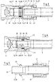
- Both the male part 8 of the coupling device 4 as well as the connection part 18 and ultimately also the union nut 9 have an additional security piece 10, 11, so that a total of an extended security shaft 40 is realized.
- This safety shaft 40 has an annular surface 39, which is practically a first sealing zone.
- the outer surface of the security piece 10 and the male part 8 are designated by the reference numeral 12 as a sealing surface, as well as the inner surface of the connecting part 18 of the lance holder 2 by the reference numeral 13. Lying these Sealing surfaces 12, 13 as in FIG. 4 shown to one another, this results in an advantageous long sealing zone.
- the counter-connection piece 35 of the safety tube 3 is formed as the opposite end of the lance holder 2, namely as the connecting part 18.
- an annular web 37 is formed, which serves as a stop for the inserted or inserted Plug-in part 8 of the safety tube 3 but also serves as a sealing zone, because here on the nut 9, a correspondingly high contact pressure can be generated.
- the extended union nut 9 corresponds with its internal thread 21 with the external thread 20 of the lance holder 2 or its connection part 18, which is in particular also FIG. 3 can take. External thread 20 and internal thread 21 result in the thread 14, over which the union nut 9 can be moved along a total of about fifteen threads 41, 42 on the connection part 18 in order to realize the individual sealing zones.
- the sealing surface 25 is activated and that at the free end 26 of the connecting part 18, which corresponds here with the support ring 22 and the inner surface 23, so that thus the mentioned sealing zone can be realized.
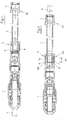
- FIG. 1 shows the not yet closed and FIG. 2 the closed coupling device 4.
- the essential seal is achieved via the ring seal 15 at the free end 26 of the female part 19 formed as a connecting part 18.
- this annular seal 15 is realized by two spaced annular grooves 28, 30 with O-rings 29, 31, wherein these two O-rings 29, 31 each form an optimum sealing zone.
- the main sealing effect remains even if the nut 9 is not properly tightened or has loosened, so that the male part 8 has pulled out of the female part 19 by a certain amount.
- the covered by the O-rings sealing surface area 33 at the male part 8 at about 33 to 50% of the sealing surface area 32 makes up, the only of the female part 19 or plug-in part 8 are formed.
- FIG. 4 clarified, in which case the extended security pieces are provided with the reference numerals 10, 11 and 14 '.
- the security piece 10 belongs to the male part 8, the security piece 11 to the union nut 9 and the security piece 14 'to the connection part 18th
- FIG. 5 makes clear that the union nut 9 is easy to move. It is shown pushed back here very far to show the male part 8 at the front end of the safety tube 3. It is formed elongated, has an acting as a sealing surface 12 annular surface 39 and provides the aforementioned multiple safety both in terms of the seal as well as in terms of stability (kink protection). All this is also of great importance, because even with the valve closed in the lance holder 2 in this area highly flammable gas is pending at high pressure.
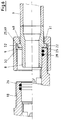
- FIG. 6 Finally, the additional sealing zone in the region of the inside of the support ring 22.
- the inside of the support ring 22 forms a slope 49 and that one of the surface bottom 48 to the outer edge 52 of the support ring 22nd leading slope 49.
- This the sealing surface 25 forming slope 49 is broken off just before the outer edge 52, so that a sealing edge 50 is formed. Since the slope 49 is at an angle of ⁇ 5 ° to the vertical, the sealing edge 50 acts in the sealing of the two metal parts advantageously supporting.
- a sealing zone is realized where the male part 8 abuts against the annular web 37.
- the second sealing zone and the third sealing zone are in the region of the O-rings 29 and 31, which is retained even when pulling out the male part 8, so that a multiple fuse is achieved.
- the fourth Sealing zone is realized when pressing the support ring 22 to the front edge of the connecting part 18 and nut member 19, while the fifth sealing zone of the two sealing surfaces 12, 13 and ring surface 39 is formed.
Landscapes
- Engineering & Computer Science (AREA)
- General Engineering & Computer Science (AREA)
- Chemical & Material Sciences (AREA)
- Mechanical Engineering (AREA)
- Materials Engineering (AREA)
- Organic Chemistry (AREA)
- Metallurgy (AREA)
- Manufacturing & Machinery (AREA)
- Quick-Acting Or Multi-Walled Pipe Joints (AREA)
- Joints With Pressure Members (AREA)
- Gasket Seals (AREA)
- Telescopes (AREA)
- Mutual Connection Of Rods And Tubes (AREA)
- Carbon Steel Or Casting Steel Manufacturing (AREA)
Description
- Die Erfindung betrifft eine mehrfach gesicherte Koppelvorrichtung für Sauerstofflanzen und andere, leicht entzündliche Gase führenden und diese Medien in die Stahlschmelze injizierende Rohre, wobei diese über einen als Ventil ausgebildeten Lanzenhalter und ein Sicherheitsrohr verfügen, das zwischen dem Lanzenhalter und einem zum Versorger führenden Lanzenschlauch angeordnet oder direkt mit dem Versorger verbunden ist.
- Ein Brennrohrhalter bzw. eine Sauerstofflanze mit Lanzenhalter ist beispielsweise aus der
EP 0 372 099 B1 bekannt. Am Sauerstoffeingang dieses Lanzenhalters ist allerdings nur ein Gewinde angedeutet, auf welches ein hier nicht gezeigtes Sicherheitsrohr aufgeschraubt wird. Solche meist aus Edelstahl bestehende Sicherheitsrohre oder Sicherheitsstrecken sind bei handbetätigten Lanzenhaltern hilfreich und dienen vor allem der Erhöhung der Betriebssicherheit, weil über sie die einwandfreie Führung der entzündlichen Gase vor allem des Sauerstoffs bis in den Lanzenhalter erreicht werden soll. Schwierig ist es allerdings, wenn bei der Koppelvorrichtung zwischen der Sauerstofflanze und der Sicherheitsstrecke bzw. dem Sicherheitsrohr unachtsam gehandelt und die Koppelvorrichtung nicht fest genug angezogen wird, weil dann das Austreten des leicht entzündlichen Gases doch auftreten kann. Von daher ist es wichtig, dass die Koppelvorrichtung immer fest angezogen ist, um die Dichtheit der Verbindung zu garantieren. Bei Unachtsamkeit ist allerdings die beschriebene Gefährdung nach wie vor vorhanden. Auch bei derEP 0 456 377 A2 ist der Dichtring dem Steckteil zugeordnet und weist eine schräge Dichtfläche auf. DieJP 58 132335 EP 1 159 513 A betrifft einen solchen Brenner. In derDE 10 2009 005 940 B3 wird ein Montagesystem gelehrt, bei dem Bauteile über eine Überwurfmutter miteinander verbunden werden. DieDE 10 2008 012 534 A1 hat einen Lanzenhalter zum Gegenstand, der mit einem Lanzenschlauch oder einem Sicherheitsrohr verbunden werden kann. - Der Erfindung liegt daher die Aufgabe zugrunde, eine Koppelvorrichtung für Sauerstoff führende Versorgungsleitungen in Stahlwerken zu schaffen, bei der gefährliche Leckagen annähernd vermieden, nach Möglichkeit sogar gänzlich ausgeschlossen sind.
- Die Aufgabe wird gemäß der Erfindung dadurch gelöst, dass das Sicherheitsrohr ein in das Anschlussteil des Lanzenhalters einführbares Steckteil aufweist, das mit einer auf den Lanzenhalter aufschraubbaren Überwurfmutter die Koppelvorrichtung bildet und wie auch Anschlussteil und Überwurfmutter um ein Sicherheitsstück verlängert ist, das ein weites Einführen in das Anschlussteil ermöglichend und damit eine Dichtwirkung auch noch bei locker aufsitzender Überwurfmutter gewährleistend ausgebildet und einmal mit mindestens einer gegen das Anschlussteil des Lanzenhalters im Bereich von Dichtflächen dichtenden, dem freien Ende des Anschlussteils zugeordneten Ringdichtung und andererseits einem verlängerten Gewinde ausgerüstet ist wobei der der Ringdichtung zugeordnete Dichtflächenbereich der Dichtfläche am verlängerten Steckteil 33-50% des Dichtflächenbereiches ausmacht, der nur vom Anschlussteil und Steckteil gebildet ist.
- Anschlussteil, Überwurfmutter und Steckteil sind um ein Sicherheitsstück verlängert ausgebildet, wobei der der Ringdichtung zugeordnete Dichtflächenbereich deutlich kürzer ist als der nur von Anschlussteil und Steckteil gebildete Dichtflächenbereich, sodass deutlich wird, welche Bemaßung des Sicherheitsstückes bei allen drei Bauteilen sich zweckmäßigerweise zu ergeben hat.Bei einer derart ausgebildeten Koppelvorrichtung zwischen Sauerstofflanze und Sicherheitsrohr ist auch dann die notwendige Sicherheit gewährleistet, wenn die Überwurfmutter nicht hundertprozentig angezogen ist. Dies erreicht die Erfindung dadurch, dass sowohl das Anschlussteil wie die Überwurfmutter wie auch das Steckteil verlängert sind, einmal um eine zusätzliche Dichtzone zu schaffen und zum anderen um bei der lockeren Anordnung der Überwurfmutter dennoch durch das verlängerte Steckteil und die zweckmäßig angebrachte Ringdichtung die notwendige Dichtheit des Systems zu gewährleisten. Die Ringdichtung ist so angeordnet, dass das Steckteil weit in das Anschlussteil des Lanzenhalters einführbar ist und die Ringdichtung erst am freien Ende des Anschlussteils angeordnet ist. Die Ringdichtung ist also auch dann immer noch wirksam, wenn das Steckteil um einen gewissen Bereich durch eine lockere Überwurfmutter aus dem Steckteil herausgezogen ist. Vorteilhaft ist darüber hinaus, dass in dem verlängerten Bereich des Steckteils bzw. im Bereich des Sicherheitsstücks eine zusätzliche Dichtfläche geschaffen ist, die das Austreten von leicht entzündlichem Gas zusätzlich erschwert bzw. unmöglich macht.
- Zweckmäßig ist es gemäß der Erfindung, wenn die Ringdichtung von zwei in beabstandeten Ringnuten angeordneten O-Ringen gebildet ist wobei das Steckteil einen über die O-Ringe der Ringdichtung vorstehenden freien Dichtflächenbereich aufweist, der doppelt so groß ist wie der von den beiden O-Ringen überdeckte Dichtflächenbereich. Damit ist eine Maßangabe gegeben, die je nach Gegebenheiten zu verwirklichen ist, ohne dass es größerer Veränderungen bedarf und die beiden O-Ringe entfalten ihre Dichtwirkung in zwei hintereinander liegenden Dichtzonen und darüber hinaus in einem verlängerten Dichtflächenbereich.
- Nach einer zweckmäßigen Ausführungsform der Erfindung ist vorgesehen, dass das Anschlussteil des Lanzenhalters als verlängertes Mutterteil dient und über die auf dem entsprechend verlängerten und als Vaterteil dienenden Steckteil des Sicherheitsrohres oder auch des Lanzenschlauches reibende Ringdichtung verfügend ausgebildet ist. Mit dieser besonderen Ausbildung ist es vorteilhaft möglich, mit dem verlängerten Vaterteil soweit in das verlängerte Mutterteil einzutauchen, dass wie schon weiter vorn erwähnt auch bei nicht ganz angezogener Überwurfmutter dennoch die notwendige Dichtheit gegeben ist. Außerdem ist ein Abkanten oder Abknicken in diesem Bereich durch das weite Ineinanderschieben beider Bauteile ausgeschlossen.
- Nach einer weiteren zweckmäßigen Ausbildung ist vorgesehen, dass dem als Steckteil dienenden Vaterteil des Sicherheitsrohres die Überwurfmutter mit einem mit dem Außengewinde des Anschlussteils korrespondierenden Innengewinde zugeordnet ist. Da beide Gewindebereiche gleich lang und gleich geformt sind, kann mit der entsprechenden Überwurfmutter die notwendig sichere Verbindung zwischen Sicherheitsrohr und Lanzenhalter gewährleistet werden.
- Ergänzend sieht die Erfindung hierzu vor, dass das Steckteil einen Stützring aufweist, gegen dessen als Dichtfläche ausgebildete Innenseite das freie Ende des Anschlussteils des Lanzenhalters über die auf dem Außengewinde verschiebbare Überwurfmutter anpressbar ist. Mit Hilfe dieser Weiterbildung ist es möglich, beim richtigen Anpressen der Überwurfmutter das Anschlussteil so gegen das Steckteil anzupressen, dass hier eine weitere Dichtzone entsteht. Dies ist von Vorteil, auch wenn dort kein gesonderter Dichtring angeordnet ist, weil die aufeinander angepassten Flächen eine entsprechende Dichtwirkung entwickeln können.
- Weiter vorne ist darauf hingewiesen worden, dass die Ringdichtung so im Anschlussteil des Lanzenhalters also im verlängerten Mutterteil angeordnet ist, dass eine Dichtwirkung auch dann noch vorhanden ist, wenn bei locker aufsitzender Überwurfmutter das Steckteil etwas aus dem Anschlussteil herausgezogen ist. Dies wird wie in Anspruch 1 festgelegt dadurch sichergestellt, dass die Ringdichtung dem freien Ende des Anschlussteils zugeordnet ist und zwar möglichst weit am freien Ende, um so die besagte Sicherung der Verbindung möglichst lange aufrecht zu erhalten.
- Am anderen Ende des Sicherheitsrohres ist der Lanzenschlauch mit dem Sicherheitsrohr verbunden. Auch hier wird eine höhere Sicherheit dadurch erreicht, dass das Sicherheitsrohres ein dem Anschlussteil des Lanzenhalters entsprechend ausgebildetes Gegenanschlussteil aufweist. Auch der Lanzenschlauch erhält dementsprechend ein Steckteil, das dem Steckteil des Sicherheitsrohres entspricht, sodass damit eine ebenso vorteilhafte Verbindung möglich ist, wie mit dem Lanzenhalter.
- Eine weitere Dichtzone erhält die vorliegende Erfindung dadurch, dass im Tiefsten des Anschlussteils des Lanzenhalters ein zugleich als Anschlag für das Steckteil dienender Ringsteg ausgebildet ist. Damit kann mit Beaufschlagung der Überwurfmutter zugleich die im Tiefsten liegende Dichtzone abgedichtet werden und die im Bereich des Stützringes, sodass zusammen mit der Ringdichtung praktisch vier Dichtzonen vorhanden sind, die für die vorteilhafte Dichtwirkung der Koppelvorrichtung von Nutzen sind.
- Die Überwurfmutter selbst ist ebenso verlängert ausgebildet, wie das Steckteil und das Anschlussteil, wobei nach einer vorteilhaften Ausbildung vorgesehen ist, dass die Überwurfmutter zehn bis zwanzig Gewindegänge aufweisend ausgebildet ist, während übliche Überwurfmuttern lediglich fünf bis sieben Gewindegänge aufweisen. Damit ist verdeutlicht, dass auch über das längere Gewinde eine zusätzliche Sicherheit gegeben ist, da auch bei einer leicht gelockerten Überwurfmutter immer noch ausreichendes Gewinde vorhanden ist, um eine Abtrennung und damit ein völliges Undichtwerden auszuschließen.
- Vorteilhaft ist es insbesondere, wenn die Überwurfmutter 15 Gewindegänge aufweisend ausgebildet ist.
- Eine dauerhafte leichte Herstellung der Verbindung zwischen Lanzenhalter und Sicherheitsrohr über die Koppelvorrichtung ist insbesondere gegeben, wenn die Überwurfmutter aus Messing und das Steckteil wie auch das übrige Sicherheitsrohr aus Edelstahl hergestellt sind. Die Überwurfmutter aus dem weniger harten Metall kann somit leichtgängig auf das ebenfalls aus Edelstahl bestehende Anschlussteil des Lanzenhalters aufgeschraubt werden.
- Neben den schon erwähnten insgesamt vier Dichtzonen ergibt sich eine fünfte Dichtzone im Bereich zwischen Steckteil und Mutterteil des Lanzenhalters dadurch, dass das Steckteil des Sicherheitsrohres und das Mutterteil des Lanzenhalters zusammen einen Sicherheitsschaft ergebend ausgeführt sind, der über eine durchgehend dichtende Ringfläche verfügt. Dieser Sicherheitsschaft hat also nicht nur die Aufgabe eine höhere Stabilität vorzugeben, sondern auch eine durchgehende Dichtfläche, die ergänzend sicherstellt, dass keinerlei leicht entzündliche Gase diesen Bereich durchfließen können.
- Eine weitere Dichtzone ist zwischen Stützring und freiem Ende des Anschlussteils geschaffen und zwar ohne gesonderten Dichtring. Nach einer zweckmäßigen Ausführungsform ist die am Stützring bestehende Dichtfläche am Stützring metallisch dicht ausgebildet, sodass Metall auf Metall liegt. Diese vorteilhafte Dichtung erreicht die Erfindung vor allem dadurch, dass die Dichtfläche vom Flächengrund ausgehend nach außen schräg gestellt ist und dabei eine Neigung von vorzugsweise 5° aufweist. Schließlich wird in dieser Schräge eine Dichtkante durch Abbruch der Schräge geschaffen, sodass eine besonders intensive Dichtung geschaffen ist, die als weitere Dichtzone wirkt.
- Die Erfindung zeichnet sich insbesondere dadurch aus, dass eine mehrfach gesicherte Koppelvorrichtung zwischen Lanzenhalter und dem anschließenden Lanzenschlauch geschaffen ist, die von erheblichem Vorteil ist, wenn zwischen Lanzenhalter und Lanzenschlauch ein Sicherheitsrohr oder eine Sicherheitsstrecke vorgesehen ist. Dieses Sicherheitsrohr verfügt beidseitig über ein die Gesamtlänge vergrößerndes Sicherheitsstück mit Dichtfläche bzw. Gewinde, sodass bei Ineinanderführen von Sicherheitsrohr und Anschlussteil des Lanzenhalters eine völlige Abdichtung dieser Koppelvorrichtung erreicht wird. Die notwendige Dichtheit ist auch dann gewährleistet, wenn durch Unachtsamkeit die Überwurfmutter nicht fest angezogen ist, wobei weitere fünf Dichtzonen diese Dichtheit unterstützen. Gerade bei dem hier angesprochenen Arbeitsgebiet, wo leicht entzündliche Gase in die Stahlschmelze injiziert werden, ist diese absolute Dichtigkeit der Verbindungsstelle enorm vorteilhaft. Außerdem genügt die Koppelvorrichtung dem besonderen Problem des dauerhaft hohen Druckes des Sauerstoffes oder sonstigen Gases im Bereich des Lanzenhalters.
- Weitere Einzelheiten und Vorteile der Erfindung ergeben sich aus der nachfolgenden Beschreibung der zugehörigen Zeichnungen, in denen ein bevorzugtes Ausführungsbeispiel mit den dazu notwendigen Einzelheiten und Einzelteilen dargestellt ist. Es zeigen:
- Figur 1
- einen Schnitt durch einen Lanzenhalter und dem noch nicht angekoppelten Sicherheitsrohr,
- Figur 2
- den Schnitt gemäß
Figur 1 mit angekoppeltem Sicherheitsrohr, - Figur 3
- einen vergrößerten Ausschnitt der Koppelverbindung nach
Figur 1 vordem Ankoppeln, - Figur 4
- einen vergrößerten Ausschnitt der Koppelverbindung nach
Figur 2 nach dem Ankoppeln, - Figur 5
- einen vergrößerten Schnitt des Sicherheitsrohres mit zurückgeschobener Überwurfmutter und
- Figur 6
- einen Schnitt mit der eine weitere Dichtzone erbringenden Dichtkante.
- Von der eigentlichen Sauerstofflanze 1 ist in
Figur 1 nur ein Teilbereich zu sehen. Diese Sauerstofflanze 1 bzw. das entsprechende Rohr wird in den Lanzenhalter 2 eingeschoben und dort wirksam festgelegt. Auf der gegenüberliegenden Seite dieses Lanzenhalters 2 ist ein Sicherheitsrohr 3 mit dem Anschlussteil 18 des Lanzenhalters 2 verbunden. Dies erfolgt über die Koppelvorrichtung 4, die aus dem Steckteil 8 des Sicherheitsrohres 3 sowie der Überwurfmutter 9 besteht. Die Überwurfmutter 9 wird auf das Anschlussteil 18 des Lanzenhalters 2 aufgeschraubt. Auf der gegenüberliegenden Seite des Sicherheitsrohres 3 ist die gleiche Koppelvorrichtung 5 vorgesehen, mit der das Sicherheitsrohr 3 mit einem Lanzenschlauch 6 verbunden wird. - Sowohl das Steckteil 8 der Koppelvorrichtung 4 wie auch das Anschlussteil 18 und letztlich auch die Überwurfmutter 9 verfügen über ein zusätzliches Sicherheitsstück 10, 11, sodass damit insgesamt ein verlängerter Sicherheitsschaft 40 verwirklicht wird. Dieser Sicherheitsschaft 40 verfügt über eine Ringfläche 39, die praktisch eine erste Dichtzone darstellt. In
Figur 3 sind daher die Außenfläche des Sicherheitsstücks 10 bzw. des Steckteils 8 mit dem Bezugszeichen 12 als Dichtfläche bezeichnet, ebenso wie die Innenfläche des Anschlussteils 18 des Lanzenhalters 2 mit dem Bezugszeichen 13. Liegen diese Dichtflächen 12, 13 wie inFigur 4 dargestellt aufeinander, ergibt sich so eine vorteilhaft lange Dichtzone. - Aus den
Figuren 1 und 2 ist zu entnehmen, dass auch das Gegenanschlussstück 35 des Sicherheitsrohres 3 so ausgebildet ist, wie das gegenüberliegende Ende des Lanzenhalters 2, nämlich wie das Anschlussteil 18. Im Tiefsten 36 dieses Anschlussstückes 35 ist ein Ringsteg 37 ausgebildet, der als Anschlag für das eingeführte oder einzuführende Steckteil 8 des Sicherheitsrohres 3 dient aber gleichzeitig auch als Dichtzone, weil hier über die Überwurfmutter 9 ein entsprechend hoher Anpressdruck erzeugt werden kann. Die verlängerte Überwurfmutter 9 korrespondiert mit ihrem Innengewinde 21 mit dem Außengewinde 20 des Lanzenhalters 2 bzw. dessen Anschlussteil 18, was man insbesondere auchFigur 3 entnehmen kann. Außengewinde 20 und Innengewinde 21 ergeben das Gewinde 14, über das die Überwurfmutter 9 über insgesamt rund fünfzehn Gewindegänge 41, 42 auf dem Anschlussteil 18 entlang verschoben werden kann, um die einzelnen Dichtzonen zu verwirklichen. - Dabei wird auch die Dichtfläche 25 aktiviert und zwar die am freien Ende 26 des Anschlussteils 18, das hier mit dem Stützring 22 bzw. dessen Innenfläche 23 korrespondiert, sodass damit die erwähnte Dichtzone verwirklicht werden kann.
-
Figur 1 zeigt die noch nicht geschlossene undFigur 2 die geschlossene Koppelvorrichtung 4. - Die wesentliche Dichtung erreicht man über die Ringdichtung 15 am freien Ende 26 des als Mutterteil 19 ausgebildeten Anschlussteils 18. Bei der in den
Figuren 1 bis 5 gezeigten Ausführung ist diese Ringdichtung 15 durch zwei beabstandete Ringnuten 28, 30 mit O-Ringen 29, 31 verwirklicht, wobei diese beiden O-Ringe 29, 31 jeweils eine optimale Dichtzone bilden. Dadurch bleibt die Hauptdichtwirkung auch dann existent, wenn die Überwurfmutter 9 nicht richtig angezogen ist oder sich gelockert hat, sodass sich das Steckteil 8 um einen gewissen Betrag aus dem Mutterteil 19 herausgezogen hat. Vorteilhaft ist es, wenn die von den O-Ringen überdeckte Dichtflächenbereich 33 am Steckteil 8 bei etwa 33 bis 50% der Dichtflächenbereich 32 ausmacht, die nur vom Mutterteil 19 bzw. Steckteil 8 gebildet sind. Entsprechendes ist inFigur 4 verdeutlicht, wobei hier die verlängerten Sicherheitsstücke mit den Bezugszeichen 10, 11 und 14' versehen sind. Das Sicherheitsstück 10 gehört zum Steckteil 8, das Sicherheitsstück 11 zur Überwurfmutter 9 und das Sicherheitsstück 14' zum Anschlussteil 18. -
Figur 5 verdeutlicht, dass die Überwurfmutter 9 leicht zu verschieben ist. Sie ist hier sehr weit zurückgeschoben dargestellt, um das Steckteil 8 am vorderen Ende des Sicherheitsrohres 3 zu zeigen. Es ist verlängert ausgebildet, weist eine als Dichtfläche 12 wirkende Ringfläche 39 auf und erbringt die erwähnte Mehrfachsicherung sowohl bezüglich der Dichtung wie auch bezüglich Stabilität (Abknicksicherung). All dies ist auch deshalb von großer Bedeutung, weil auch bei geschlossenem Ventil im Lanzenhalter 2 in diesem Bereich leicht entzündliches Gas mit hohem Druck ansteht. -
Figur 6 schließlich zeigt die zusätzliche Dichtzone im Bereich der Innenseite des Stützringes 22. Im oberen Teilbereich mit dem aus der Überwurfmutter 9 herausgezogenen Vaterventil 8 ist erkennbar, dass die Innenseite des Stützringes 22 eine Schräge 49 bildet und zwar eine vom Flächengrund 48 zum Außenrand 52 des Stützringes 22 hoch führende Schräge 49. Diese die Dichtfläche 25 bildende Schräge 49 ist kurz vor dem Außenrand 52 abgebrochen, sodass eine Dichtkante 50 entsteht. Da die Schräge 49 unter einem Winkel von ∼ 5° zur Senkrechten steht, wirkt die Dichtkante 50 bei der Dichtung der beiden aus Metall bestehenden Teile vorteilhaft unterstützend. - Zusammenfassend wird noch einmal darauf hingewiesen, dass bei der erfindungsgemäßen Koppelvorrichtung vier bzw. auch insgesamt fünf Dichtzonen verwirklicht werden, die dafür sorgen, dass bei optimaler Koppelvorrichtung aber auch bei gelockerter Koppelvorrichtung immer noch die notwendige Dichtung gegeben ist, die das Austreten der leicht entzündlichen Gase insbesondere des Sauerstoffs unterbinden. Eine Dichtzone ist dort verwirklicht, wo das Steckteil 8 gegen den Ringsteg 37 stößt. Die zweite Dichtzone und die dritte Dichtzone liegen im Bereich der O-Ringe 29 und 31, wobei diese auch beim Herausziehen des Steckteils 8 erhalten bleibt, so dass eine Mehrfachsicherung erreicht ist. Die vierte Dichtzone wird beim Anpressen des Stützringes 22 an die Vorderkante des Anschlussteils 18 bzw. Mutterteils 19 verwirklicht, während die fünfte Dichtzone von den beiden Dichtflächen 12, 13 bzw. Ringfläche 39 gebildet wird. Damit ist eine optimal sichere Verbindung von Lanzenhalter 2 und Sicherheitsrohr 3 bzw. gegebenenfalls auch Lanzenschlauch 6 immer gegeben.
- Alle genannten Merkmale, auch die den Zeichnungen allein zu entnehmenden, werden allein und in Kombination als erfindungswesentlich angesehen.
Claims (14)
- Mehrfach gesicherte Koppelvorrichtung (4) für Sauerstofflanzen (1) und andere, leicht entzündliche Gase führenden und diese Medien in die Stahlschmelze injizierende Rohre, wobei diese über ein Ventil, in Form eines Lanzenhalters (2) und ein zwischengeschaltetes Sicherheitsrohr (3), und die Koppelvorrichtung (4,5) mit einem zum Versorger führenden Lanzenschlauch (6) verbunden ist, dadurch gekennzeichnet,
dass das Sicherheitsrohr (3) ein in das Anschlussteil (18) des Lanzenhalters (2) einführbares Steckteil (8) aufweist, das mit einer auf den Lanzenhalter (2) aufschraubbaren Überwurfmutter (9) die Koppelvorrichtung (4) bildet und wie auch Anschlussteil (18) und Überwurfmutter (9) um ein Sicherheitsstück (10, 11, 14') verlängert ist, das ein weites Einführen in das Anschlussteil (18) ermöglichend und damit eine Dichtwirkung auch noch bei locker aufsitzender Überwurfmutter (9) gewährleistend ausgebildet und einmal mit mindestens einer gegen das Anschlussteil (18) des Lanzenhalters (2) im Bereich von Dichtflächen (12, 13) dichtenden, dem freien Ende (26) des Anschlussteils (18) zugeordneten Ringdichtung (15) und andererseits einem verlängerten Gewinde (14) ausgerüstet ist, wobei der der Ringdichtung (15) zugeordnete Dichtflächenbereich (33) der Dichtfläche (12, 13) am verlängerten Steckteil (8) 33-50% des Dichtflächenbereiches (32) ausmacht, die nur vom Anschlussteil (18) und Steckteil (8) gebildet ist. - Koppelvorrichtung nach Anspruch 1,
dadurch gekennzeichnet,
dass die Ringdichtung (15) von zwei in beanstandeten Ringnuten (28, 30) angeordneten O-Ringen (29, 31) gebildet ist. - Koppelvorrichtung nach Anspruch 1,
dadurch gekennzeichnet
dass das Anschlussteil (18) des Lanzenhalters (2) als verlängertes Mutterteil (19) dient und über die auf dem entsprechend verlängerten und als Vaterteil dienenden Steckteil (8) des Sicherheitsrohres (3) oder auch des Lanzenschlauches (6) reibende Ringdichtung (15) verfügend ausgebildet ist. - Koppelvorrichtung nach Anspruch 1,
dadurch gekennzeichnet,
dass dem als Steckteil (8) dienenden Vaterteil des Sicherheitsrohres (3) die Überwurfmutter (9) mit einem mit dem Außengewinde (20) des Anschlussteils (18) korrespondierenden Innengewinde (21) zugeordnet ist. - Koppelvorrichtung nach Anspruch 4,
dadurch gekennzeichnet,
dass das Steckteil (8) einen Stützring (22) aufweist, gegen dessen als Dichtfläche (25) ausgebildete Innenseite das freie Ende (26) des Anschlussteils (18) des Lanzenhalters (2) über die auf dem Außengewinde (20) verschiebbare Überwurfmutter (9) anpressbar ist. - Koppelvorrichtung nach einem der vorhergehenden Ansprüche,
dadurch gekennzeichnet,
dass das Sicherheitsrohr (3) ein dem Anschlussteil (18) des Lanzenhalters (2) entsprechend ausgebildetes Gegenanschlussteil (35) aufweist. - Koppelvorrichtung nach einem der vorhergehenden Ansprüche,
dadurch gekennzeichnet,
dass im Tiefsten (36) des Anschlussteils (18) des Lanzenhalters (2) ein zugleich als Anschlag für das Steckteil (8) dienender Ringsteg (37) ausgebildet ist. - Koppelvorrichtung nach einem der vorhergehenden Ansprüche,
dadurch gekennzeichnet,
dass die Überwurfmutter (9) zehn bis zwanzig Gewindegänge (41, 42) aufweisend ausgebildet ist. - Koppelvorrichtung nach Anspruch 8,
dadurch gekennzeichnet,
dass die Überwurfmutter (9) fünfzehn Gewindegänge (41, 42) aufweisend ausgebildet ist. - Koppelvorrichtung nach einem der vorhergehenden Ansprüche,
dadurch gekennzeichnet,
dass die Überwurfmutter (9) aus Messing und das Steckteil (8) wie auch das übrige Sicherheitsrohr (3) aus Edelstahl hergestellt sind. - Koppelvorrichtung nach einem der vorhergehenden Ansprüche,
dadurch gekennzeichnet,
dass das Steckteil (8) des Sicherheitsrohres (3) und das Mutterteil (19) des Lanzenhalters (2) zusammen einen Sicherheitsschaft (40) ergebend ausgeführt sind, der über eine durchgehend dichtende Ringfläche (39) verfügt. - Koppelvorrichtung nach Anspruch 5,
dadurch gekennzeichnet,
dass die Dichtfläche (25) am Stützring (22) metallisch dicht ausgebildet ist. - Koppelvorrichtung nach Anspruch 12,
dadurch gekennzeichnet
dass die Dichtfläche (25) vom Flächengrund (48) ausgehend nach außen schräg gestellt und dabei eine Neigung von 5° zur Senkrechten aufweisend ausgebildet ist. - Koppelvorrichtung nach Anspruch 13,
dadurch gekennzeichnet
dass die Schräge (49) der Dichtfläche (25) kurz vor dem Außenrand (52) des Stützringes (22) eine Dichtkante (50) bildend abgebrochen ausgeführt ist.
Priority Applications (1)
| Application Number | Priority Date | Filing Date | Title |
|---|---|---|---|
| PL11817466T PL2659009T3 (pl) | 2010-12-28 | 2011-12-15 | Wielokrotnie zabezpieczony mechanizm sprzęgający do lanc tlenowych |
Applications Claiming Priority (3)
| Application Number | Priority Date | Filing Date | Title |
|---|---|---|---|
| DE102010056153 | 2010-12-28 | ||
| DE102011014323A DE102011014323A1 (de) | 2010-12-28 | 2011-03-18 | Mehrfach gesicherte Koppelvorrichtung für Sauerstofflanzen |
| PCT/DE2011/002127 WO2012089188A2 (de) | 2010-12-28 | 2011-12-15 | Mehrfach gesicherte koppelvorrichtung für sauerstofflanzen |
Publications (2)
| Publication Number | Publication Date |
|---|---|
| EP2659009A2 EP2659009A2 (de) | 2013-11-06 |
| EP2659009B1 true EP2659009B1 (de) | 2018-02-28 |
Family
ID=45592110
Family Applications (1)
| Application Number | Title | Priority Date | Filing Date |
|---|---|---|---|
| EP11817466.3A Active EP2659009B1 (de) | 2010-12-28 | 2011-12-15 | Mehrfach gesicherte koppelvorrichtung für sauerstofflanzen |
Country Status (13)
| Country | Link |
|---|---|
| US (1) | US9500306B2 (de) |
| EP (1) | EP2659009B1 (de) |
| JP (1) | JP6084166B2 (de) |
| KR (1) | KR101805963B1 (de) |
| CN (1) | CN103429763B (de) |
| BR (1) | BR112013016111B1 (de) |
| DE (1) | DE102011014323A1 (de) |
| ES (1) | ES2663599T3 (de) |
| PL (1) | PL2659009T3 (de) |
| PT (1) | PT2659009T (de) |
| TR (1) | TR201806980T4 (de) |
| TW (1) | TWI575073B (de) |
| WO (1) | WO2012089188A2 (de) |
Families Citing this family (4)
| Publication number | Priority date | Publication date | Assignee | Title |
|---|---|---|---|---|
| US9572171B2 (en) * | 2013-10-31 | 2017-02-14 | Intel IP Corporation | Systems, methods, and devices for efficient device-to-device channel contention |
| CN104989891B (zh) * | 2015-07-10 | 2018-08-21 | 秦皇岛北方管业有限公司 | 一种长寿命防泄漏氧枪冷却水金属软管 |
| US10888886B2 (en) * | 2017-12-19 | 2021-01-12 | Raytheon Technologies Corporation | Modular cold-spray receiver |
| KR102176953B1 (ko) * | 2020-07-28 | 2020-11-10 | 주식회사 비비씨 | 랜스 파이프용 고정홀더 |
Family Cites Families (38)
| Publication number | Priority date | Publication date | Assignee | Title |
|---|---|---|---|---|
| US2829673A (en) * | 1954-08-24 | 1958-04-08 | Ind Instr Corp | Pipe unions |
| US3202442A (en) * | 1961-05-19 | 1965-08-24 | Aeroquip Corp | Coupling |
| US3201148A (en) * | 1963-05-16 | 1965-08-17 | Chatleff Controls Inc | Coupling means for connecting conduits |
| US3476414A (en) * | 1966-11-30 | 1969-11-04 | United States Steel Corp | Pipe joint |
| US3533649A (en) * | 1969-01-30 | 1970-10-13 | Genova Products | Pipe fitting |
| US3900223A (en) * | 1974-01-23 | 1975-08-19 | Sundstrand Corp | Pipe coupling |
| DE2650370C2 (de) * | 1975-11-12 | 1986-12-04 | Kjell Ronny Zug Ekman | Verriegelbare Leitungskupplung |
| SE444712B (sv) * | 1980-06-06 | 1986-04-28 | Ekman K R | Kopplingsanordning med han- och hondelar och dessa tilldelade lasorgan |
| US4555129A (en) * | 1980-12-09 | 1985-11-26 | Davlin Irwin H | Adapter union and improved adapter member therefor |
| JPS58132335U (ja) | 1982-02-26 | 1983-09-06 | テイサン株式会社 | 自動着火式切断用ト−チ |
| US4801160A (en) * | 1981-09-17 | 1989-01-31 | Michael J. Caddell | High-pressure fluid flow connector |
| JPS619972A (ja) * | 1984-06-26 | 1986-01-17 | Fuaiaaransu Kogyo Kk | ランス用管体の着脱方法及びその着脱確認装置 |
| JPS6246190U (de) * | 1985-09-03 | 1987-03-20 | ||
| US5678607A (en) * | 1986-01-15 | 1997-10-21 | Krywitsky; Lee A. | Reusable pipe union and pipe cap assembly for wide thermal cycling |
| US4750765A (en) * | 1987-07-27 | 1988-06-14 | Stratoflex, Inc. | Quick-connect coupling |
| JPH01159513A (ja) | 1987-12-15 | 1989-06-22 | Tanaka Seisakusho:Kk | 切断火口 |
| DE3880841D1 (de) | 1988-12-02 | 1993-06-09 | Beda Oxygentech Armatur | Kompaktlanze mit rohrverdrehsicherung. |
| US5060988A (en) * | 1990-05-08 | 1991-10-29 | Nwd International, Inc. | Hydraulic coupling |
| LU87761A1 (fr) * | 1990-07-04 | 1992-03-11 | Wurth Paul Sa | Dispositif d'accouplement automatique d'une lance d'insufflation a une tete de raccord |
| US5110160A (en) * | 1990-08-23 | 1992-05-05 | Fluid Line Products, Inc. | High pressure port fitting system |
| JPH11257570A (ja) * | 1998-03-11 | 1999-09-21 | Nippon Grease Nipple Kk | 高温流体を通すフッ素樹脂製管状部材用のフッ素樹脂製継手 |
| NO310372B1 (no) * | 1999-08-02 | 2001-06-25 | Bakke Technology As | Delt koplingsanordning med gjennomgående boring |
| JP2001159495A (ja) * | 1999-12-03 | 2001-06-12 | San-Ei Faucet Mfg Co Ltd | 配管用ヘッダー |
| JP2002022074A (ja) * | 2000-07-06 | 2002-01-23 | Zexel Valeo Climate Control Corp | 管継手 |
| US6481761B2 (en) * | 2001-02-21 | 2002-11-19 | Visteon Global Technologies, Inc. | Frusto-conical seal fitting |
| CN100406797C (zh) * | 2001-12-25 | 2008-07-30 | 未来工业株式会社 | 水管的端部结构及制造方法、水管 |
| US7077436B1 (en) * | 2002-05-06 | 2006-07-18 | Hilltap Fittings, Ltd. | Gear operated coupler |
| US7032677B2 (en) * | 2003-06-27 | 2006-04-25 | H W Ces International | Multi-lock adapters for independent screwed wellheads and methods of using same |
| US7159652B2 (en) * | 2003-09-04 | 2007-01-09 | Oil States Energy Services, Inc. | Drilling flange and independent screwed wellhead with metal-to-metal seal and method of use |
| KR100497010B1 (ko) * | 2005-03-15 | 2005-06-27 | (주) 영진산기 | 래들에 남아있는 지금을 제거하기 위한 산소홀더 |
| US7690693B2 (en) * | 2005-08-04 | 2010-04-06 | Parker-Hannifin Corporation | Pre-assemblable, push-in fitting connection for corrugated tubing |
| JP4456567B2 (ja) * | 2006-02-01 | 2010-04-28 | 東尾メック株式会社 | 管継手 |
| CA2690214A1 (en) * | 2007-06-18 | 2008-12-24 | Weidmann Ltd. | Connecting arrangement for a pipe union |
| JP5311795B2 (ja) * | 2007-10-25 | 2013-10-09 | 旭有機材工業株式会社 | 管継手 |
| DE102008012554B4 (de) | 2008-03-04 | 2011-12-22 | Beda Oxygentechnik Armaturen Gmbh | Lanzenhalter |
| CN201259046Y (zh) * | 2008-07-28 | 2009-06-17 | 简明锐 | 一种连接接头 |
| JP2010065386A (ja) * | 2008-09-08 | 2010-03-25 | Amagasaki Juki Kk | 油圧配管連結装置 |
| DE102009005940B3 (de) | 2009-01-23 | 2010-07-08 | Henco Industries Nv | Montagesystem eines Fittings mit einem Rohr und einem Montagekörper |
-
2011
- 2011-03-18 DE DE102011014323A patent/DE102011014323A1/de not_active Withdrawn
- 2011-10-21 TW TW100138193A patent/TWI575073B/zh active
- 2011-12-15 EP EP11817466.3A patent/EP2659009B1/de active Active
- 2011-12-15 BR BR112013016111-6A patent/BR112013016111B1/pt active IP Right Grant
- 2011-12-15 PT PT118174663T patent/PT2659009T/pt unknown
- 2011-12-15 US US13/977,085 patent/US9500306B2/en active Active
- 2011-12-15 JP JP2013546587A patent/JP6084166B2/ja active Active
- 2011-12-15 CN CN201180063516.5A patent/CN103429763B/zh active Active
- 2011-12-15 KR KR1020137016392A patent/KR101805963B1/ko active IP Right Grant
- 2011-12-15 PL PL11817466T patent/PL2659009T3/pl unknown
- 2011-12-15 WO PCT/DE2011/002127 patent/WO2012089188A2/de active Application Filing
- 2011-12-15 TR TR2018/06980T patent/TR201806980T4/tr unknown
- 2011-12-15 ES ES11817466.3T patent/ES2663599T3/es active Active
Also Published As
| Publication number | Publication date |
|---|---|
| EP2659009A2 (de) | 2013-11-06 |
| US20130285373A1 (en) | 2013-10-31 |
| WO2012089188A3 (de) | 2012-11-01 |
| KR20130135874A (ko) | 2013-12-11 |
| BR112013016111A2 (pt) | 2018-07-10 |
| JP2014509371A (ja) | 2014-04-17 |
| PT2659009T (pt) | 2018-04-03 |
| BR112013016111B1 (pt) | 2019-05-28 |
| CN103429763A (zh) | 2013-12-04 |
| PL2659009T3 (pl) | 2018-08-31 |
| KR101805963B1 (ko) | 2017-12-06 |
| US9500306B2 (en) | 2016-11-22 |
| TWI575073B (zh) | 2017-03-21 |
| ES2663599T3 (es) | 2018-04-16 |
| TR201806980T4 (tr) | 2018-06-21 |
| CN103429763B (zh) | 2016-02-03 |
| TW201226574A (en) | 2012-07-01 |
| DE102011014323A1 (de) | 2012-06-28 |
| JP6084166B2 (ja) | 2017-02-22 |
| WO2012089188A2 (de) | 2012-07-05 |
Similar Documents
| Publication | Publication Date | Title |
|---|---|---|
| EP0207339A1 (de) | Verbindungsanordnung mit einer Schraubmuffe | |
| EP2659009B1 (de) | Mehrfach gesicherte koppelvorrichtung für sauerstofflanzen | |
| EP2192338A2 (de) | Anschlussstück | |
| DD207748A5 (de) | Dichtung fuer stahlrohre, insbesondere aus stahl oder legierungen | |
| DE102013109123A1 (de) | Verbindung zwischen einem Verbindungsteil, einem Rohrteil und einem Hülsenteil, Verfahren zur Verbindung zwischen einem Verbindungsteil, einem Rohrteil und einem Hülsenteil, Einführteil zum Einführen eines Rohrendes und kreisringförmiges Rückzug-Sperrteil | |
| DE808173C (de) | Rohr- und Schlauchkupplung | |
| DE2934491C2 (de) | Mauerdurchführung | |
| DE102017207053B4 (de) | Abgasrohr sowie Verfahren zum Ablängen eines Abgasrohres | |
| DE669605C (de) | Rohrverbindung zum elastischen Kuppeln eines glatten Rohrendes, insbesondere eines Asbestzementrohres, mit einem einen Flansch aufweisenden Anschlussstueck | |
| DE19818571C2 (de) | Rohrverschraubung zur mediendichten Verbindung von Rohrendstücken | |
| DE102008062823B3 (de) | Klemmverschraubung zum Befestigen von länglichen Körpern oder Rohren | |
| DE1911064A1 (de) | Selbstblockierende Rohrverbindung | |
| DE102007036504B4 (de) | Anordnung aus einem rohrförmigen Bauteil und einem Anschlussstück | |
| DE3731222C2 (de) | ||
| DE2512016C2 (de) | Heizkörperverschraubung | |
| DE202006017177U1 (de) | Fluidleitungsverbindungsanordnung | |
| DE19731565C1 (de) | Rohrverschraubung | |
| WO2010139512A1 (de) | Verschluss, stahlhülse und vorrichtung zur kalibrierung des koenen-tests | |
| DE102007007780C5 (de) | Richtungseinstellbare Rohrverschraubung | |
| DE202007000951U1 (de) | Einwandiges röhrenförmiges Element für Rauchzüge, das mit Schnellverschlussmitteln ausgestattet ist | |
| DE3636082C2 (de) | Gas-Hausanschlußvorrichtung | |
| DE3404632A1 (de) | Schnellverbindung fuer rohre | |
| DE4107048A1 (de) | Verbindung eines mit einem aussenprofil versehenen, rohrfoermigen anschlussstutzens mit einem anschlussstueck, verfahren sowie zwischenstueck und anschlussstueck zur herstellung der verbindung und verwendung der verbindung | |
| EP2774670A1 (de) | Reaktor | |
| DE102011017315B4 (de) | Steckkupplung für medienführende Leitungen mit zwei unter beengten Bedingungen verbindbaren Kupplungselementen |
Legal Events
| Date | Code | Title | Description |
|---|---|---|---|
| PUAI | Public reference made under article 153(3) epc to a published international application that has entered the european phase |
Free format text: ORIGINAL CODE: 0009012 |
|
| 17P | Request for examination filed |
Effective date: 20130729 |
|
| AK | Designated contracting states |
Kind code of ref document: A2 Designated state(s): AL AT BE BG CH CY CZ DE DK EE ES FI FR GB GR HR HU IE IS IT LI LT LU LV MC MK MT NL NO PL PT RO RS SE SI SK SM TR |
|
| DAX | Request for extension of the european patent (deleted) | ||
| 17Q | First examination report despatched |
Effective date: 20161107 |
|
| GRAP | Despatch of communication of intention to grant a patent |
Free format text: ORIGINAL CODE: EPIDOSNIGR1 |
|
| RIC1 | Information provided on ipc code assigned before grant |
Ipc: C21C 5/46 20060101AFI20170928BHEP Ipc: F16L 19/02 20060101ALI20170928BHEP |
|
| INTG | Intention to grant announced |
Effective date: 20171017 |
|
| GRAS | Grant fee paid |
Free format text: ORIGINAL CODE: EPIDOSNIGR3 |
|
| GRAA | (expected) grant |
Free format text: ORIGINAL CODE: 0009210 |
|
| AK | Designated contracting states |
Kind code of ref document: B1 Designated state(s): AL AT BE BG CH CY CZ DE DK EE ES FI FR GB GR HR HU IE IS IT LI LT LU LV MC MK MT NL NO PL PT RO RS SE SI SK SM TR |
|
| REG | Reference to a national code |
Ref country code: GB Ref legal event code: FG4D Free format text: NOT ENGLISH Ref country code: CH Ref legal event code: EP |
|
| REG | Reference to a national code |
Ref country code: AT Ref legal event code: REF Ref document number: 974194 Country of ref document: AT Kind code of ref document: T Effective date: 20180315 |
|
| REG | Reference to a national code |
Ref country code: IE Ref legal event code: FG4D Free format text: LANGUAGE OF EP DOCUMENT: GERMAN |
|
| REG | Reference to a national code |
Ref country code: DE Ref legal event code: R096 Ref document number: 502011013838 Country of ref document: DE Ref country code: CH Ref legal event code: NV Representative=s name: FELBER UND PARTNER AG, CH |
|
| REG | Reference to a national code |
Ref country code: PT Ref legal event code: SC4A Ref document number: 2659009 Country of ref document: PT Date of ref document: 20180403 Kind code of ref document: T Free format text: AVAILABILITY OF NATIONAL TRANSLATION Effective date: 20180327 |
|
| REG | Reference to a national code |
Ref country code: RO Ref legal event code: EPE Ref country code: ES Ref legal event code: FG2A Ref document number: 2663599 Country of ref document: ES Kind code of ref document: T3 Effective date: 20180416 |
|
| REG | Reference to a national code |
Ref country code: NL Ref legal event code: FP |
|
| REG | Reference to a national code |
Ref country code: SE Ref legal event code: TRGR |
|
| REG | Reference to a national code |
Ref country code: NO Ref legal event code: T2 Effective date: 20180228 |
|
| REG | Reference to a national code |
Ref country code: LT Ref legal event code: MG4D |
|
| PG25 | Lapsed in a contracting state [announced via postgrant information from national office to epo] |
Ref country code: CY Free format text: LAPSE BECAUSE OF FAILURE TO SUBMIT A TRANSLATION OF THE DESCRIPTION OR TO PAY THE FEE WITHIN THE PRESCRIBED TIME-LIMIT Effective date: 20180228 Ref country code: LT Free format text: LAPSE BECAUSE OF FAILURE TO SUBMIT A TRANSLATION OF THE DESCRIPTION OR TO PAY THE FEE WITHIN THE PRESCRIBED TIME-LIMIT Effective date: 20180228 Ref country code: HR Free format text: LAPSE BECAUSE OF FAILURE TO SUBMIT A TRANSLATION OF THE DESCRIPTION OR TO PAY THE FEE WITHIN THE PRESCRIBED TIME-LIMIT Effective date: 20180228 |
|
| PG25 | Lapsed in a contracting state [announced via postgrant information from national office to epo] |
Ref country code: LV Free format text: LAPSE BECAUSE OF FAILURE TO SUBMIT A TRANSLATION OF THE DESCRIPTION OR TO PAY THE FEE WITHIN THE PRESCRIBED TIME-LIMIT Effective date: 20180228 Ref country code: BG Free format text: LAPSE BECAUSE OF FAILURE TO SUBMIT A TRANSLATION OF THE DESCRIPTION OR TO PAY THE FEE WITHIN THE PRESCRIBED TIME-LIMIT Effective date: 20180528 Ref country code: RS Free format text: LAPSE BECAUSE OF FAILURE TO SUBMIT A TRANSLATION OF THE DESCRIPTION OR TO PAY THE FEE WITHIN THE PRESCRIBED TIME-LIMIT Effective date: 20180228 |
|
| REG | Reference to a national code |
Ref country code: GR Ref legal event code: EP Ref document number: 20180400954 Country of ref document: GR Effective date: 20180829 |
|
| PG25 | Lapsed in a contracting state [announced via postgrant information from national office to epo] |
Ref country code: MT Free format text: LAPSE BECAUSE OF FAILURE TO SUBMIT A TRANSLATION OF THE DESCRIPTION OR TO PAY THE FEE WITHIN THE PRESCRIBED TIME-LIMIT Effective date: 20180228 |
|
| PG25 | Lapsed in a contracting state [announced via postgrant information from national office to epo] |
Ref country code: AL Free format text: LAPSE BECAUSE OF FAILURE TO SUBMIT A TRANSLATION OF THE DESCRIPTION OR TO PAY THE FEE WITHIN THE PRESCRIBED TIME-LIMIT Effective date: 20180228 Ref country code: EE Free format text: LAPSE BECAUSE OF FAILURE TO SUBMIT A TRANSLATION OF THE DESCRIPTION OR TO PAY THE FEE WITHIN THE PRESCRIBED TIME-LIMIT Effective date: 20180228 |
|
| REG | Reference to a national code |
Ref country code: DE Ref legal event code: R097 Ref document number: 502011013838 Country of ref document: DE |
|
| PG25 | Lapsed in a contracting state [announced via postgrant information from national office to epo] |
Ref country code: SM Free format text: LAPSE BECAUSE OF FAILURE TO SUBMIT A TRANSLATION OF THE DESCRIPTION OR TO PAY THE FEE WITHIN THE PRESCRIBED TIME-LIMIT Effective date: 20180228 Ref country code: DK Free format text: LAPSE BECAUSE OF FAILURE TO SUBMIT A TRANSLATION OF THE DESCRIPTION OR TO PAY THE FEE WITHIN THE PRESCRIBED TIME-LIMIT Effective date: 20180228 |
|
| PLBE | No opposition filed within time limit |
Free format text: ORIGINAL CODE: 0009261 |
|
| STAA | Information on the status of an ep patent application or granted ep patent |
Free format text: STATUS: NO OPPOSITION FILED WITHIN TIME LIMIT |
|
| 26N | No opposition filed |
Effective date: 20181129 |
|
| PG25 | Lapsed in a contracting state [announced via postgrant information from national office to epo] |
Ref country code: SI Free format text: LAPSE BECAUSE OF FAILURE TO SUBMIT A TRANSLATION OF THE DESCRIPTION OR TO PAY THE FEE WITHIN THE PRESCRIBED TIME-LIMIT Effective date: 20180228 |
|
| PG25 | Lapsed in a contracting state [announced via postgrant information from national office to epo] |
Ref country code: MC Free format text: LAPSE BECAUSE OF FAILURE TO SUBMIT A TRANSLATION OF THE DESCRIPTION OR TO PAY THE FEE WITHIN THE PRESCRIBED TIME-LIMIT Effective date: 20180228 |
|
| REG | Reference to a national code |
Ref country code: IE Ref legal event code: MM4A |
|
| PG25 | Lapsed in a contracting state [announced via postgrant information from national office to epo] |
Ref country code: IE Free format text: LAPSE BECAUSE OF NON-PAYMENT OF DUE FEES Effective date: 20181215 |
|
| PG25 | Lapsed in a contracting state [announced via postgrant information from national office to epo] |
Ref country code: MK Free format text: LAPSE BECAUSE OF NON-PAYMENT OF DUE FEES Effective date: 20180228 Ref country code: HU Free format text: LAPSE BECAUSE OF FAILURE TO SUBMIT A TRANSLATION OF THE DESCRIPTION OR TO PAY THE FEE WITHIN THE PRESCRIBED TIME-LIMIT; INVALID AB INITIO Effective date: 20111215 |
|
| PG25 | Lapsed in a contracting state [announced via postgrant information from national office to epo] |
Ref country code: IS Free format text: LAPSE BECAUSE OF FAILURE TO SUBMIT A TRANSLATION OF THE DESCRIPTION OR TO PAY THE FEE WITHIN THE PRESCRIBED TIME-LIMIT Effective date: 20180628 |
|
| PGFP | Annual fee paid to national office [announced via postgrant information from national office to epo] |
Ref country code: SK Payment date: 20231127 Year of fee payment: 13 |
|
| PGFP | Annual fee paid to national office [announced via postgrant information from national office to epo] |
Ref country code: GR Payment date: 20231220 Year of fee payment: 13 Ref country code: GB Payment date: 20231219 Year of fee payment: 13 |
|
| PGFP | Annual fee paid to national office [announced via postgrant information from national office to epo] |
Ref country code: TR Payment date: 20231127 Year of fee payment: 13 Ref country code: SE Payment date: 20231222 Year of fee payment: 13 Ref country code: RO Payment date: 20231128 Year of fee payment: 13 Ref country code: PT Payment date: 20231124 Year of fee payment: 13 Ref country code: NO Payment date: 20231219 Year of fee payment: 13 Ref country code: NL Payment date: 20231226 Year of fee payment: 13 Ref country code: LU Payment date: 20231226 Year of fee payment: 13 Ref country code: IT Payment date: 20231221 Year of fee payment: 13 Ref country code: FR Payment date: 20231226 Year of fee payment: 13 Ref country code: FI Payment date: 20231228 Year of fee payment: 13 Ref country code: DE Payment date: 20231215 Year of fee payment: 13 Ref country code: CZ Payment date: 20231128 Year of fee payment: 13 Ref country code: AT Payment date: 20231219 Year of fee payment: 13 |
|
| PGFP | Annual fee paid to national office [announced via postgrant information from national office to epo] |
Ref country code: PL Payment date: 20231121 Year of fee payment: 13 Ref country code: BE Payment date: 20231226 Year of fee payment: 13 |
|
| PGFP | Annual fee paid to national office [announced via postgrant information from national office to epo] |
Ref country code: ES Payment date: 20240118 Year of fee payment: 13 |
|
| PGFP | Annual fee paid to national office [announced via postgrant information from national office to epo] |
Ref country code: CH Payment date: 20240102 Year of fee payment: 13 |