EP2656064B1 - Dissolved nitrogen concentration monitoring method and substrate cleaning method - Google Patents
Dissolved nitrogen concentration monitoring method and substrate cleaning method Download PDFInfo
- Publication number
- EP2656064B1 EP2656064B1 EP11805808.0A EP11805808A EP2656064B1 EP 2656064 B1 EP2656064 B1 EP 2656064B1 EP 11805808 A EP11805808 A EP 11805808A EP 2656064 B1 EP2656064 B1 EP 2656064B1
- Authority
- EP
- European Patent Office
- Prior art keywords
- dissolved
- nitrogen concentration
- oxygen concentration
- dissolved nitrogen
- cleaning
- Prior art date
- Legal status (The legal status is an assumption and is not a legal conclusion. Google has not performed a legal analysis and makes no representation as to the accuracy of the status listed.)
- Active
Links
- IJGRMHOSHXDMSA-UHFFFAOYSA-N Atomic nitrogen Chemical compound N#N IJGRMHOSHXDMSA-UHFFFAOYSA-N 0.000 title claims description 264
- 238000004140 cleaning Methods 0.000 title claims description 148
- 229910052757 nitrogen Inorganic materials 0.000 title claims description 125
- 238000000034 method Methods 0.000 title claims description 62
- 239000000758 substrate Substances 0.000 title claims description 43
- 238000012544 monitoring process Methods 0.000 title claims description 40
- QVGXLLKOCUKJST-UHFFFAOYSA-N atomic oxygen Chemical compound [O] QVGXLLKOCUKJST-UHFFFAOYSA-N 0.000 claims description 122
- 239000001301 oxygen Substances 0.000 claims description 122
- 229910052760 oxygen Inorganic materials 0.000 claims description 122
- 239000007788 liquid Substances 0.000 claims description 68
- XLYOFNOQVPJJNP-UHFFFAOYSA-N water Substances O XLYOFNOQVPJJNP-UHFFFAOYSA-N 0.000 claims description 26
- 239000007789 gas Substances 0.000 claims description 24
- 229910001873 dinitrogen Inorganic materials 0.000 claims description 14
- 230000007423 decrease Effects 0.000 claims description 8
- 238000007348 radical reaction Methods 0.000 claims description 8
- 239000000203 mixture Substances 0.000 claims description 6
- MYMOFIZGZYHOMD-UHFFFAOYSA-N Dioxygen Chemical compound O=O MYMOFIZGZYHOMD-UHFFFAOYSA-N 0.000 claims description 5
- 230000008859 change Effects 0.000 claims description 5
- 230000001678 irradiating effect Effects 0.000 claims description 4
- 229910021642 ultra pure water Inorganic materials 0.000 description 72
- 239000012498 ultrapure water Substances 0.000 description 72
- 239000002245 particle Substances 0.000 description 30
- 238000010586 diagram Methods 0.000 description 21
- 238000005259 measurement Methods 0.000 description 18
- 230000008569 process Effects 0.000 description 10
- XUIMIQQOPSSXEZ-UHFFFAOYSA-N Silicon Chemical compound [Si] XUIMIQQOPSSXEZ-UHFFFAOYSA-N 0.000 description 9
- 229910052710 silicon Inorganic materials 0.000 description 9
- 239000010703 silicon Substances 0.000 description 9
- 238000002474 experimental method Methods 0.000 description 8
- 238000003969 polarography Methods 0.000 description 8
- 238000003860 storage Methods 0.000 description 8
- 230000008878 coupling Effects 0.000 description 6
- 238000010168 coupling process Methods 0.000 description 6
- 238000005859 coupling reaction Methods 0.000 description 6
- 238000004506 ultrasonic cleaning Methods 0.000 description 6
- 230000009467 reduction Effects 0.000 description 5
- 238000006722 reduction reaction Methods 0.000 description 5
- VYPSYNLAJGMNEJ-UHFFFAOYSA-N Silicium dioxide Chemical compound O=[Si]=O VYPSYNLAJGMNEJ-UHFFFAOYSA-N 0.000 description 4
- 238000005070 sampling Methods 0.000 description 4
- 239000004065 semiconductor Substances 0.000 description 4
- QGZKDVFQNNGYKY-UHFFFAOYSA-N Ammonia Chemical compound N QGZKDVFQNNGYKY-UHFFFAOYSA-N 0.000 description 3
- 239000001257 hydrogen Substances 0.000 description 3
- 229910052739 hydrogen Inorganic materials 0.000 description 3
- 239000002184 metal Substances 0.000 description 3
- 229910052751 metal Inorganic materials 0.000 description 3
- KRHYYFGTRYWZRS-UHFFFAOYSA-N Fluorane Chemical compound F KRHYYFGTRYWZRS-UHFFFAOYSA-N 0.000 description 2
- VEXZGXHMUGYJMC-UHFFFAOYSA-N Hydrochloric acid Chemical compound Cl VEXZGXHMUGYJMC-UHFFFAOYSA-N 0.000 description 2
- MHAJPDPJQMAIIY-UHFFFAOYSA-N Hydrogen peroxide Chemical compound OO MHAJPDPJQMAIIY-UHFFFAOYSA-N 0.000 description 2
- 230000003247 decreasing effect Effects 0.000 description 2
- 238000007598 dipping method Methods 0.000 description 2
- 230000000694 effects Effects 0.000 description 2
- 239000008151 electrolyte solution Substances 0.000 description 2
- 238000004519 manufacturing process Methods 0.000 description 2
- 150000002739 metals Chemical class 0.000 description 2
- 125000004433 nitrogen atom Chemical group N* 0.000 description 2
- 229910017464 nitrogen compound Inorganic materials 0.000 description 2
- 150000002830 nitrogen compounds Chemical class 0.000 description 2
- 239000000243 solution Substances 0.000 description 2
- 239000000126 substance Substances 0.000 description 2
- 229910052581 Si3N4 Inorganic materials 0.000 description 1
- 229910021529 ammonia Inorganic materials 0.000 description 1
- 238000011088 calibration curve Methods 0.000 description 1
- 238000006243 chemical reaction Methods 0.000 description 1
- 239000000356 contaminant Substances 0.000 description 1
- 230000007547 defect Effects 0.000 description 1
- 238000001035 drying Methods 0.000 description 1
- -1 e.g. Chemical compound 0.000 description 1
- 239000000284 extract Substances 0.000 description 1
- 239000010419 fine particle Substances 0.000 description 1
- 239000012530 fluid Substances 0.000 description 1
- 239000011521 glass Substances 0.000 description 1
- 230000002209 hydrophobic effect Effects 0.000 description 1
- 239000012535 impurity Substances 0.000 description 1
- 239000004973 liquid crystal related substance Substances 0.000 description 1
- 230000007246 mechanism Effects 0.000 description 1
- 239000011859 microparticle Substances 0.000 description 1
- 239000011259 mixed solution Substances 0.000 description 1
- 229920005597 polymer membrane Polymers 0.000 description 1
- 239000000843 powder Substances 0.000 description 1
- 238000006479 redox reaction Methods 0.000 description 1
- HQVNEWCFYHHQES-UHFFFAOYSA-N silicon nitride Chemical compound N12[Si]34N5[Si]62N3[Si]51N64 HQVNEWCFYHHQES-UHFFFAOYSA-N 0.000 description 1
Images

Classifications
-
- G—PHYSICS
- G01—MEASURING; TESTING
- G01N—INVESTIGATING OR ANALYSING MATERIALS BY DETERMINING THEIR CHEMICAL OR PHYSICAL PROPERTIES
- G01N29/00—Investigating or analysing materials by the use of ultrasonic, sonic or infrasonic waves; Visualisation of the interior of objects by transmitting ultrasonic or sonic waves through the object
- G01N29/02—Analysing fluids
-
- G—PHYSICS
- G01—MEASURING; TESTING
- G01N—INVESTIGATING OR ANALYSING MATERIALS BY DETERMINING THEIR CHEMICAL OR PHYSICAL PROPERTIES
- G01N33/00—Investigating or analysing materials by specific methods not covered by groups G01N1/00 - G01N31/00
- G01N33/18—Water
-
- B—PERFORMING OPERATIONS; TRANSPORTING
- B08—CLEANING
- B08B—CLEANING IN GENERAL; PREVENTION OF FOULING IN GENERAL
- B08B3/00—Cleaning by methods involving the use or presence of liquid or steam
- B08B3/04—Cleaning involving contact with liquid
- B08B3/10—Cleaning involving contact with liquid with additional treatment of the liquid or of the object being cleaned, e.g. by heat, by electricity or by vibration
- B08B3/12—Cleaning involving contact with liquid with additional treatment of the liquid or of the object being cleaned, e.g. by heat, by electricity or by vibration by sonic or ultrasonic vibrations
-
- H—ELECTRICITY
- H01—ELECTRIC ELEMENTS
- H01L—SEMICONDUCTOR DEVICES NOT COVERED BY CLASS H10
- H01L21/00—Processes or apparatus adapted for the manufacture or treatment of semiconductor or solid state devices or of parts thereof
- H01L21/02—Manufacture or treatment of semiconductor devices or of parts thereof
- H01L21/02041—Cleaning
- H01L21/02043—Cleaning before device manufacture, i.e. Begin-Of-Line process
- H01L21/02052—Wet cleaning only
-
- H—ELECTRICITY
- H01—ELECTRIC ELEMENTS
- H01L—SEMICONDUCTOR DEVICES NOT COVERED BY CLASS H10
- H01L21/00—Processes or apparatus adapted for the manufacture or treatment of semiconductor or solid state devices or of parts thereof
- H01L21/67—Apparatus specially adapted for handling semiconductor or electric solid state devices during manufacture or treatment thereof; Apparatus specially adapted for handling wafers during manufacture or treatment of semiconductor or electric solid state devices or components ; Apparatus not specifically provided for elsewhere
- H01L21/67005—Apparatus not specifically provided for elsewhere
- H01L21/67011—Apparatus for manufacture or treatment
- H01L21/67017—Apparatus for fluid treatment
- H01L21/67028—Apparatus for fluid treatment for cleaning followed by drying, rinsing, stripping, blasting or the like
- H01L21/6704—Apparatus for fluid treatment for cleaning followed by drying, rinsing, stripping, blasting or the like for wet cleaning or washing
- H01L21/67057—Apparatus for fluid treatment for cleaning followed by drying, rinsing, stripping, blasting or the like for wet cleaning or washing with the semiconductor substrates being dipped in baths or vessels
-
- H—ELECTRICITY
- H01—ELECTRIC ELEMENTS
- H01L—SEMICONDUCTOR DEVICES NOT COVERED BY CLASS H10
- H01L21/00—Processes or apparatus adapted for the manufacture or treatment of semiconductor or solid state devices or of parts thereof
- H01L21/67—Apparatus specially adapted for handling semiconductor or electric solid state devices during manufacture or treatment thereof; Apparatus specially adapted for handling wafers during manufacture or treatment of semiconductor or electric solid state devices or components ; Apparatus not specifically provided for elsewhere
- H01L21/67005—Apparatus not specifically provided for elsewhere
- H01L21/67242—Apparatus for monitoring, sorting or marking
- H01L21/67253—Process monitoring, e.g. flow or thickness monitoring
-
- Y—GENERAL TAGGING OF NEW TECHNOLOGICAL DEVELOPMENTS; GENERAL TAGGING OF CROSS-SECTIONAL TECHNOLOGIES SPANNING OVER SEVERAL SECTIONS OF THE IPC; TECHNICAL SUBJECTS COVERED BY FORMER USPC CROSS-REFERENCE ART COLLECTIONS [XRACs] AND DIGESTS
- Y10—TECHNICAL SUBJECTS COVERED BY FORMER USPC
- Y10T—TECHNICAL SUBJECTS COVERED BY FORMER US CLASSIFICATION
- Y10T436/00—Chemistry: analytical and immunological testing
- Y10T436/17—Nitrogen containing
- Y10T436/176152—Total nitrogen determined
-
- Y—GENERAL TAGGING OF NEW TECHNOLOGICAL DEVELOPMENTS; GENERAL TAGGING OF CROSS-SECTIONAL TECHNOLOGIES SPANNING OVER SEVERAL SECTIONS OF THE IPC; TECHNICAL SUBJECTS COVERED BY FORMER USPC CROSS-REFERENCE ART COLLECTIONS [XRACs] AND DIGESTS
- Y10—TECHNICAL SUBJECTS COVERED BY FORMER USPC
- Y10T—TECHNICAL SUBJECTS COVERED BY FORMER US CLASSIFICATION
- Y10T436/00—Chemistry: analytical and immunological testing
- Y10T436/20—Oxygen containing
- Y10T436/207497—Molecular oxygen
- Y10T436/209163—Dissolved or trace oxygen or oxygen content of a sealed environment
Definitions
- the present invention relates to a dissolved nitrogen concentration monitoring method, substrate cleaning method, and substrate cleaning apparatus for a wafer cleaning process. More specifically, the present invention relates to a dissolved nitrogen concentration monitoring method, substrate cleaning method, and substrate cleaning apparatus for monitoring the dissolved nitrogen concentration of a cleaning liquid into which a substrate, such as a wafer, is dipped.
- a substrate cleaning process using dipping, single-wafer, or like method is performed to remove factors responsible for defect of semiconductor devices.
- factors include organic substances, metal impurities, particles (fine particles), and chemical oxide films.
- a substrate cleaning process employs various types of cleaning methods depending on the purpose.
- a substrate is dipped into a cleaning liquid contained in a cleaning bath, and ultrasonic waves are irradiated onto the cleaning liquid where the substrate is dipped.
- ultrasonic waves are called megasonic waves, whose frequency range is around 1 MHz. It is generally recognized that use of ultrasonic waves in a frequency range of around 1 MHz reduces damage to the substrate and increases the effectiveness of cleaning micro particles of submicron sizes on the substrate.
- the particle removal efficiency is known to be affected by the dissolved nitrogen concentration of a cleaning liquid. Specifically, in a specific range of the dissolved nitrogen concentration of a cleaning liquid, the particle removal efficiency for substrate increases. If the dissolved nitrogen concentration of a cleaning liquid is monitored and controlled to be in a certain range during the cleaning process, effective removal of particles is theoretically possible.
- Patent Document 1 gas components contained in a fluid medium are introduced into a container through a polymer membrane, and the concentration of the gas components are calculated based on changes in the thermal conductivity in the container. This method has been employed to monitor the dissolved nitrogen concentration of a cleaning liquid.
- Irradiation of ultrasonic waves onto sample water containing nitrogen gas generates hydrogen radicals derived from water molecules.
- the hydrogen radicals react with the nitrogen gas, and nitrogen compounds (NO x - , NH 4 + ) are produced.
- a method based on this mechanism has been proposed for calculating the dissolved nitrogen concentration of a sample (Patent Document 2).
- the ion amount derived from nitrogen atoms is measured by a resistivity meter, and the dissolved nitrogen concentration of the sample is calculated based on the ion amount.
- the dissolved oxygen concentration of gas components are measured using the polarography method or the like, and measurements of the dissolved oxygen concentration are used to correct the value of the dissolved nitrogen concentration for calculation thereof.
- measurement of the dissolved oxygen concentration needs to be performed in addition to measurement of the dissolved nitrogen concentration, which requires complicated operations.
- this method requires more than 10 seconds for each measurement of the thermal conductivity of gas components. As the dissolved nitrogen concentration cannot be monitored real-time, the monitoring is not accurate.
- the ion amount derived from nitrogen atoms cannot be accurately measured with presence of another component ionized in sample water, and the dissolved nitrogen concentration of the sample water cannot be accurately calculated.
- This method is focused only on changes in the amount of nitrogen compounds due to ultrasonic wave irradiation, but not on changes in the dissolved oxygen concentration.
- Patent Document 3 discloses a dissolved nitrogen concentration monitoring method of monitoring a dissolved nitrogen concentration of a cleaning liquid when an ultrasonic wave is irradiated onto the cleaning liquid in which a substrate is dipped.
- the dissolved nitrogen concentration is directly determined by a dissolved nitrogen concentration sensor in pure water before mixed with other components of the cleaning liquid. Due to the addition of other components to the cleaning liquid, the dissolved nitrogen concentration of the sample water cannot be accurately calculated.
- a dissolved nitrogen concentration monitoring method directed to monitoring a dissolved nitrogen concentration of a cleaning liquid when an ultrasonic wave is irradiated onto the cleaning liquid in which a substrate is dipped.
- the dissolved nitrogen concentration monitoring method is characterized by comprising the steps of: measuring an increase amount of dissolved oxygen concentration of the cleaning liquid, which is due to an oxygen molecule generated from a water molecule as a result of a radical reaction caused by ultrasonic wave irradiation; and calculating a dissolved nitrogen concentration of the cleaning liquid from the measured increase amount of dissolved oxygen concentration based on a predetermined relationship between a dissolved nitrogen concentration and an increase amount of dissolved oxygen concentration.
- the dissolved nitrogen concentration of the cleaning liquid is calculated from an increase amount of dissolved oxygen concentration measured by a dissolved oxygen concentration meter based on dissolved gas information indicating a relationship between the dissolved nitrogen concentration of the cleaning liquid and the increase amount of dissolved oxygen concentration thereof.
- the dissolved gas information is compiled in advance for each of cleaning conditions of the substrate.
- the cleaning conditions of the substrate include an ultrasonic output power level.
- the dissolved gas information indicates that as the ultrasonic output power level increases, the increase amount of dissolved oxygen concentration corresponding to a specific dissolved nitrogen concentration increases.
- the cleaning conditions of the substrate include an overflow rate of a cleaning liquid.
- the dissolved gas information indicates that as the overflow rate decreases, a rate of change in the increase amount of dissolved oxygen concentration increases with respect to the dissolved nitrogen concentration.
- the cleaning liquid is water.
- the substrate cleaning method of the present invention is a method for cleaning a substrate by irradiating an ultrasonic wave onto a cleaning liquid into which the substrate is dipped.
- the increase amount of the dissolved oxygen concentration in the cleaning liquid which is due to an oxygen molecule generated from a water molecule as a result of a radical reaction caused by ultrasonic wave irradiation, is measured.
- the mixture ratio of a cleaning liquid with dissolved nitrogen gas, which is to be introduced into a cleaning bath is adjusted so that the increase amount of the dissolved oxygen concentration is in a specific range where the cleaning performance is high.
- the substrate cleaning apparatus of the present invention is an apparatus for cleaning a substrate by irradiating an ultrasonic wave to a cleaning liquid into which the substrate is dipped.
- This apparatus measures the increase amount of the dissolved oxygen concentration in the cleaning liquid, which is due to an oxygen molecule generated from a water molecule as a result of a radical reaction caused by ultrasonic wave irradiation.
- this apparatus adjusts the mixture ratio of a cleaning liquid with dissolved nitrogen gas, which is to be introduced into a cleaning bath, so that the increase amount of the dissolved oxygen concentration is in a specific range where the cleaning performance is high.
- an increase amount of dissolved oxygen concentration which is due to oxygen molecules generated from water molecules as a result of a radical reaction caused by ultrasonic wave irradiation, is measured. Then the dissolved nitrogen concentration of a cleaning liquid is calculated from the measured increase amount of dissolved oxygen concentration based on a predetermined relationship between the dissolved nitrogen concentration and the increase amount of dissolved oxygen concentration.
- the dissolved nitrogen concentration can be calculated by measuring the dissolved oxygen concentration of a cleaning liquid, no complicated operation is required. Since the relationship between the dissolved nitrogen concentration and the increase amount of dissolved oxygen concentration is predetermined, the dissolved nitrogen concentration can be accurately calculated using this relationship.
- Cost reduction is also possible as use of expensive dissolved nitrogen concentration meters is not necessary, and real-time measurement is possible since the dissolved oxygen concentration can be measured using a dissolved oxygen concentration meter of the polarography type or the like.
- real-time accurate monitoring of the dissolved nitrogen concentration of a cleaning liquid can be made without complicated operations.
- the relationship between the dissolved nitrogen concentration of a cleaning liquid and the increase amount of dissolved oxygen concentration thereof is indicated by dissolved gas information. Based on this information, the dissolved nitrogen concentration of the cleaning liquid is calculated from the increase amount of dissolved oxygen concentration measured by a dissolved oxygen concentration meter. As an inexpensive dissolved oxygen concentration meter can be used for measurement of the dissolved nitrogen concentration, further cost reduction is possible.
- the dissolved gas information is produced in advance for each of substrate cleaning conditions, even when a cleaning condition is changed, the dissolved nitrogen concentration of a cleaning liquid can be accurately calculated.
- the aforementioned substrate cleaning conditions include the ultrasonic output power level. Even when the output power level of ultrasonic waves irradiated onto a cleaning liquid is changed, the dissolved nitrogen concentration can be accurately calculated based on the dissolved gas information that corresponds to the changed output power level.
- the aforementioned dissolved gas information indicates that as the ultrasonic output power level increases, the increase amount of dissolved oxygen concentration corresponding to a specific dissolved nitrogen concentration increases. By increasing the ultrasonic output power level, the calculatable value of the dissolved nitrogen concentration increases, and the accuracy of measurement thereof increases.
- the aforementioned substrate cleaning conditions include the overflow rate of a cleaning liquid. Even when the overflow rate of a cleaning liquid is changed, the dissolved nitrogen concentration can be accurately calculated based on the dissolved gas information that corresponds to the changed overflow rate.
- the aforementioned dissolved gas information indicates that as the overflow rate decreases, the rate of change in the increase amount of dissolved oxygen concentration increases with respect to the dissolved nitrogen concentration. By decreasing the overflow rate, the dissolved nitrogen concentration can be accurately calculated.
- the mixture ratio of a cleaning liquid with dissolved nitrogen gas, which is to be introduced into a cleaning bath is adjusted so that the increase amount of the dissolved oxygen concentration is in a specific range where the cleaning performance is high.
- Substrate cleaning with a high particle removal efficiency can be achieved without using a dissolved nitrogen concentration meter.
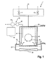
- FIG. 1 is a diagram schematically showing a configuration of an ultrasonic cleaning apparatus to which a monitoring method according to an embodiment of the present invention is applied.
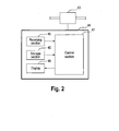
- FIG. 2 is a block diagram showing a configuration of a monitoring unit that performs the monitoring method according the present embodiment.
- an ultrasonic cleaning apparatus 1 is comprised of a supply unit 10, a coupling bath 21, an irradiation unit 30, and a monitoring unit 40.
- the supply unit 10 supplies a cleaning liquid, such as ultrapure water, to a cleaning bath 20.
- the coupling bath 21 houses the cleaning bath 20.
- the irradiation unit 30 is disposed at the bottom of the coupling bath 21 and irradiates ultrasonic waves onto inside the cleaning bath 20.
- the monitoring unit 40 monitors the dissolved nitrogen concentration of the cleaning liquid supplied to inside the cleaning bath 20.
- the supply unit 10 has a first supply valve 11 that supplies ultrapure water with dissolved nitrogen gas to a below-described mixed bath and a second supply valve 12 that supplies degassed ultrapure water to the below-described mixed bath.
- the ultrapure water with dissolved nitrogen gas and the degassed ultrapure water are mixed at a location downstream from the first supply valve 11 and the second supply valve 12.
- the mixed pure water is supplied to a liquid introduction pipe, which will be described below, via a pipe installed inside the cleaning bath 20.
- the cleaning bath 20 has a wafer holder 22 that holds inside a wafer W, e.g., a semiconductor wafer, and stores the mixed ultrapure water while the wafer holder 22 is holding a substrate W.
- the substrate W is thereby dipped into the mixed cleaning liquid in the cleaning bath 20.
- Liquid introduction pipes 23 are arranged at a lower portion of the cleaning bath 20, so that the liquid introduction pipes 23 supply the mixed ultrapure water to the cleaning bath at a predetermined overflow rate.
- the coupling bath 21 is connected with a supply line (not shown) other than the supply unit 10 and is supplied with water at a predetermined overflow rate.
- the irradiation unit 30 irradiates the ultrasonic waves onto the mixed ultrapure water in the cleaning bath 20 via the water stored in the coupling bath 21.
- the wafer W dipped in the mixed ultrapure water is thereby cleaned. It is preferable to use ultrasonic waves whose frequency ranges from 400 kHz to 1 MHz.
- the monitoring unit 40 includes a sampling pipe 41, a pump 42, a dissolved oxygen concentration meter 43, and a determination unit 44.
- the sampling pipe 41 extracts the mixed ultrapure water in a predetermined amount.
- the pump 42 is connected to the sampling pipe 41 and supplies a predetermined amount of mixed ultrapure water to a below-described dissolved oxygen concentration meter.
- the dissolved oxygen concentration meter 43 which is connected to the pump 42 at a location downstream thereof, measures the dissolved oxygen concentration of the mixed ultrapure water and sends electric signals corresponding to the measured dissolved oxygen concentration to the below-described determination unit.
- the determination unit 44 determines the dissolved nitrogen concentration in the cleaning bath 20 based on the electric signals sent from the dissolved oxygen concentration meter 43.
- the dissolved oxygen concentration meter 43 is, for example, a dissolved oxygen concentration meter using the polarography method.
- polarography method two types of metals are dipped in an electrolyte solution, and a certain voltage is applied between the two metals to cause an oxidation reduction reaction. Then the current proportional to the dissolved oxygen concentration of the electrolyte solution is measured.
- the determination unit 44 has a receiving section 45, a storage section 46, a control section 47, and a display 48.
- the receiving section 45 receives electric signals from the dissolved oxygen concentration meter 43.
- the storage section 46 stores dissolved gas information, which indicates a predetermined relationship between the dissolved nitrogen concentration and the increase amount of dissolved oxygen concentration.
- the control section 47 calculates the increase amount of dissolved oxygen concentration based on the electric signals received from the receiving section 45 when ultrasonic waves are irradiated.
- control section 47 calculates the dissolved nitrogen concentration of a cleaning liquid from the increase amount of dissolved oxygen concentration measured by a dissolved oxygen concentration meter based on the dissolved gas information, which indicates the relationship between the dissolved nitrogen concentration of the cleaning liquid and the increase amount of dissolved oxygen concentration thereof.
- the display 48 displays the dissolved nitrogen concentration calculated by the control section 47.
- the control section 47 performs overall control of each section of the monitoring unit 40 and reads out a program stored in the storage section 46 to execute the below-described dissolved nitrogen concentration calculating process ( FIG. 7 ).
- the particle removal efficiency of a cleaning method using ultrasonic waves is affected by the dissolved nitrogen concentration of ultrapure water. Specifically, it is known that the particle removal efficiency for a wafer increases when the dissolved nitrogen concentration of a cleaning liquid is in a specific range.
- the present inventors focused on dissolved oxygen concentration, which can be effortlessly measured at low costs, and found out a method for monitoring the dissolved nitrogen concentration of a cleaning liquid. In this method, the dissolved nitrogen concentration is calculated based on the dissolved oxygen concentration during irradiation of ultrasonic waves. The specifics of this monitoring method are explained in the text to follow.
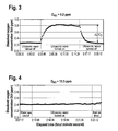
- FIG. 3 is a diagram showing changes in the dissolved oxygen concentration of ultrapure water when ultrasonic waves are irradiated onto ultrapure water.
- ultrapure water with a dissolved nitrogen concentration D N2 of 0.2 ppm is used to explain changes in the dissolved oxygen concentration.
- the cleaning bath 20 in FIGs. 3 and 4 is a rectangular water bath made of 3.0 mm-thick plates of quartz glass. The internal dimensions of this bath were 270 mm wide ⁇ 69 mm deep ⁇ 270 mm high, and its capacity was 5 L. The volume of ultrapure water supplied to the cleaning bath 20 is 5 L/min.
- the frequency and output power level of the used ultrasonic waves were 950 kHz and 1200 W (watt density 5.6 W/cm 2 ), respectively.
- the irradiated area of a vibration plate was 80 mm ⁇ 270 mm, and ultrasonic waves were irradiated onto the whole bottom surface of the cleaning bath 20.
- irradiation of ultrasonic waves onto ultrapure water with an initial dissolved oxygen concentration D 0 of approximately 0.25 ppm causes the dissolved oxygen concentration to increase to approximately 0.8 ppm.
- the dissolved oxygen concentration of the ultrapure water decreases to the level of the initial dissolved oxygen concentration.
- the above trends show that the dissolved oxygen concentration of ultrapure water is increased by ultrasonic wave irradiation.
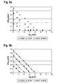
- FIG. 4 is a diagram showing changes in the dissolved oxygen concentration of ultrapure water when ultrasonic waves are irradiated onto ultrapure water.
- the dissolved nitrogen concentration D N2 is 13.5 ppm.
- this equation can be used to calculate the dissolved nitrogen concentration D N2 .
- the dissolved nitrogen concentration D N2 corresponds to the increase amount of dissolved oxygen concentration ⁇ D O2 measured by the dissolved oxygen concentration meter 43.
- the dissolved nitrogen concentration of the ultrapure water can be monitored by performing the aforementioned calculation. For example, if changes in the increase amount of dissolved oxygen concentration ⁇ D O2 are monitored, the increase and decrease in the dissolved nitrogen concentration D N2 can be monitored using the above equation.
- the increase amount of dissolved oxygen concentration ⁇ D O2 corresponding to an arbitrary dissolved nitrogen concentration D N2 is calculated and the increase amount of dissolved oxygen concentration of a cleaning liquid ⁇ D O2 is monitored, it is possible to determine whether the dissolved nitrogen concentration of the cleaning liquid is greater, smaller, or equal to the arbitrary dissolved nitrogen concentration D N2 .
- the present inventors conducted a survey to identify factors influencing the relationship between the dissolved nitrogen concentration D N2 of ultrapure water and the increase amount of dissolved oxygen concentration thereof ⁇ D O2 .
- the survey identified that this relationship is influenced by the following factors: (1) the output power level of ultrasonic waves irradiated onto the ultrapure water; and (2) the overflow rate of ultrapure water supplied to the cleaning bath 20.
- the text to follow explains the relationship between D N2 and ⁇ D O2 at different ultrasonic output power levels and at different overflow rates of ultrapure water.
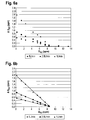
- FIGs. 5 (a) and (b) are diagrams that indicate a relationship between the dissolved nitrogen concentration D N2 of ultrapure water and the increase amount of dissolved oxygen concentration thereof ⁇ D O2 for each ultrasonic output power level.
- FIG. 5 (a) is a diagram plotting measurements of the ultrasonic output power levels.
- FIG. 5 (b) is a diagram depicting approximation equations for each ultrasonic output power levels.
- FIG. 5(a) depicts the results of selecting 900 W (watt density: 4.2 W/cm 2 ), 1000 W (watt density: 4.6 W/cm 2 ), 1100 W (watt density: 5.1 W/cm 2 ), and 1200 W (watt density: 5.6 W/cm 2 ) as ultrasonic output power levels and plotting values indicating the relationship between D N2 and ⁇ D O2 at the above output power levels. Approximation equations (calibration curves) determined from the plotted values have the slopes and y-intercepts presented in the drawing ( FIG. 5(b) ). The plotted values of FIG.
- the cleaning bath 20 which is a rectangular water bath made of 3.0 mm-thick plates of quartz glass.
- the internal dimensions of this bath were 270 mm wide ⁇ 69 mm deep ⁇ 270 mm high, and its capacity is 5 L.
- the volume of ultrapure water supplied to the cleaning bath 20 was 5 L/min.
- the frequency of the used ultrasonic waves was 950 kHz.
- the irradiated area of a transducer was 80 mm ⁇ 270 mm, and ultrasonic waves were irradiated onto the whole bottom surface of the cleaning bath 20.
- FIGs. 6 (a) and (b) are diagrams that indicate the relationship between the dissolved nitrogen concentration D N2 of ultrapure water and the increase amount of dissolved oxygen concentration thereof ⁇ D O2 for each overflow rate of ultrapure water.
- FIG. 6 (a) is a diagram plotting each measurement of the overflow rates.
- FIG. 6 (b) is a diagram depicting approximation equations of overflow rates.
- FIG. 6(a) depicts the results of selecting 5 L/min, 2.5 L/min, and 1 L/min as overflow rates of ultrapure water and plotting values indicating the relationship between D N2 and ⁇ D O2 at the above overflow rates. Approximation equations determined from the plotted values have the slopes and y-intercepts presented in the drawing ( FIG. 6(b) ).
- the plotted values of FIG. 6(a) were obtained from measurement conducted using the cleaning bath 20, which is a rectangular water bath made of 3.0 mm-thick plates of quartz glass. The internal dimensions of this bath were 270 mm wide ⁇ 69 mm deep ⁇ 270 mm high, and its capacity is 5 L.
- the frequency and output power level of the used ultrasonic waves were 950 kHz and 1200 W (watt density: 5.6 W/cm 2 ), respectively.
- the irradiated area of a transducer was 80 mm ⁇ 270 mm, and ultrasonic waves were irradiated onto the whole bottom surface of the cleaning bath 20.
- dissolved gas information it is preferable to compile in advance dissolved gas information, as shown in FIGs. 3 and 4 , on cleaning conditions, such as ultrasonic output power level and overflow rate, and to store the compiled information in the storage section 46.
- An approximation equation that corresponds to the ultrasonic output power level or overflow rate actually used in a wafer cleaning process can be selected from the dissolved gas information stored in the storage section 46.
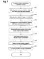
- FIG. 7 is a flowchart of a dissolved nitrogen concentration calculation process executed during performance of the monitoring method according to the embodiment of the present invention.
- a predetermined amount of mixed ultrapure water is extracted from the cleaning bath 20 (step S71). Then the dissolved oxygen concentration meter 43 is used to measure the initial dissolved oxygen concentration D 0 prior to ultrasonic wave irradiation (step S72). Next, while ultrasonic waves at a predetermined output power level are irradiated onto the cleaning bath 20, a predetermined amount of mixed ultrapure water is extracted from the cleaning bath 20 (step S73), and the dissolved oxygen concentration D O2 during ultrasonic wave irradiation is measured by the dissolved oxygen concentration meter 43 (step S74).
- the increase amount of dissolved oxygen concentration ⁇ D O2 is calculated by subtracting the initial dissolved oxygen concentration D 0 from the measured dissolved oxygen concentration D O2 (step S75). Subsequently, an approximation equation corresponding to the predetermined overflow rate or ultrasonic output power level is read out from the storage section 46 (step S76), and the approximation equation read out from the storage section 46 is used to calculate the dissolved nitrogen concentration D N2 of the mixed ultrapure water from the increase amount of dissolved oxygen concentration ⁇ D O2 measured in step S75 (step S77). Upon completion thereof, the dissolved nitrogen concentration calculation process is terminated.
- the increase amount of dissolved oxygen concentration ⁇ D O2 which is due to a radical reaction in a cleaning liquid irradiated with ultrasonic waves, is measured.
- the dissolved nitrogen concentration D N2 of the cleaning liquid is calculated from the measured increase amount of dissolved oxygen concentration ⁇ D O2 based on a predetermined relationship between the dissolved nitrogen concentration and the increase amount of dissolved oxygen concentration. Namely, as the dissolved nitrogen concentration D N2 can be calculated by measuring the dissolved oxygen concentration D O2 of the cleaning liquid, complicated operations are exempted. Also, since the relationship between the dissolved nitrogen concentration and the increase amount of dissolved oxygen concentration is predetermined, this relationship can be used to accurately calculate the dissolved nitrogen concentration D N2 . In addition, cost reduction is possible as an expensive dissolved nitrogen concentration meter does not need to be used. As well as cost reduction, accurate monitoring of the dissolved nitrogen concentration D N2 of the cleaning liquid can be achieved without complicated operations.
- the dissolved oxygen concentration meter 43 is of the polarography type.
- the type of dissolved oxygen concentration meter is not limited to the polarography type. It may be of the galvanic cell type.
- the cleaning liquid is ultrapure water, but the type of the cleaning liquid is not limited to ultrapure water. It may be generally used water. Any cleaning liquid whose dissolved oxygen can be accurately measured by a dissolved oxygen concentration meter of the polarography type or the like may be used. A mixed solution of hydrogen peroxide and ammonia (SC-1, APM) with a high ability to remove particles and organic contaminant may be used as well.
- SC-1, APM hydrogen peroxide and ammonia
- a wafer W is cleaned as the target substrate of the cleaning process, but it is not limited to the wafer W.
- Another substrate such as a glass substrate for liquid crystal display or hard disk drives, may be cleaned as well.
- the mixture ratio of ultrapure water with dissolved nitrogen gas (the first supply valve 11) to degassed ultrapure water (the second supply valve 12) is adjusted to produce a cleaning liquid with dissolved nitrogen gas.
- the above embodiment is not limited thereto.
- the dissolved nitrogen concentration of ultrapure water may be directly adjusted by adjusting the pressure of nitrogen gas dissolved in the ultrapure water using a regulator (not shown) or the like.
- the present inventors conducted the following experiment:
- a p-type silicon wafer with a diameter of 200 mm was dipped in hydrofluoric acid with a concentration of 0.5% for five minutes to remove a native oxide film from a surface thereof so that it is hydrophobic.
- Particle removal efficiency Number of particles before cleaning - Number of particles after cleaning / Number of particles before cleaning ⁇ 100 %
- the silicon wafer cleaning experiment was conducted using the ultrasonic cleaning apparatus shown in Fig. 1 .
- the cleaning bath 20 is a rectangular water bath made of 3.0 mm-thick plates of quartz glass.
- the internal dimensions of this bath are 270 mm wide ⁇ 69 mm deep ⁇ 270 mm high, and its capacity is 5 L.
- the supply flow rate of ultrapure water supplied to the cleaning bath 20 was 5 L/min.
- the frequency of the used ultrasonic waves was 950 kHz, and the output was 1200 W (watt density: 5.6 W/cm 2 ).
- the irradiated area of a transducer was 80 mm ⁇ 270 mm, and ultrasonic waves were irradiated onto the whole bottom surface of the cleaning bath 20.
- the amount of the valve opening of the first supply valve 11 that supplies ultrapure water with dissolved nitrogen gas and that of the second supply valve 12 that supplies degassed ultrapure water were adjusted.
- the dissolved nitrogen concentration and flow rate of the ultrapure water to be supplied to inside the cleaning bath 20 were thereby controlled.
- the flow rate was controlled to be 5 L/min.
- Ultrasonic waves were irradiated onto the ultrapure water in the cleaning bath 20.
- the value of ⁇ D O2 was measured by the monitoring unit 40.
- a dissolved oxygen concentration meter of the polarography type was used as the dissolved oxygen concentration meter 43.
- the amount of the valve opening of the first supply valve 11 that supplies ultrapure water with dissolved nitrogen gas and that of the second supply valve 12 that supplies degassed ultrapure water were adjusted so that the ⁇ D O2 values are 0 ppm, 0.05 ppm, 0.1 ppm, 0.2 ppm, 0.3 ppm, 0.35 ppm, 0.4 ppm, and 0.5 ppm.
- the cleaning experiment was conducted at these eight ⁇ D O2 values.
- the silicon wafer intentionally contaminated for particle removal efficiency measurement produced in (1) above was dipped for ten minutes and subsequently dried by a spin drier for two minutes.
- Fig. 8 shows the relationship between ⁇ D O2 and the particle removal efficiency obtained from the results of the cleaning experiment.
- the particle removal efficiency is found to be high in the ⁇ D O2 value range between 0.1 and 0.3 ppm.
- the mixture ratio of ultrapure water with dissolved nitrogen gas (the first supply valve 11) to degassed ultrapure water (the second supply valve 12) was adjusted so that the ⁇ D O2 value ranges between 0.1 and 0.3 ppm. It is found that by making such an adjustment, cleaning with a high particle removal efficiency is possible without using a dissolved nitrogen concentration meter.
Landscapes
- Engineering & Computer Science (AREA)
- Physics & Mathematics (AREA)
- General Physics & Mathematics (AREA)
- Condensed Matter Physics & Semiconductors (AREA)
- Manufacturing & Machinery (AREA)
- Computer Hardware Design (AREA)
- Microelectronics & Electronic Packaging (AREA)
- Power Engineering (AREA)
- Chemical & Material Sciences (AREA)
- Life Sciences & Earth Sciences (AREA)
- Health & Medical Sciences (AREA)
- Analytical Chemistry (AREA)
- Biochemistry (AREA)
- General Health & Medical Sciences (AREA)
- Immunology (AREA)
- Pathology (AREA)
- Acoustics & Sound (AREA)
- Food Science & Technology (AREA)
- Medicinal Chemistry (AREA)
- Cleaning Or Drying Semiconductors (AREA)
- Investigating Or Analyzing Non-Biological Materials By The Use Of Chemical Means (AREA)
Applications Claiming Priority (2)
| Application Number | Priority Date | Filing Date | Title |
|---|---|---|---|
| JP2010283078A JP5298112B2 (ja) | 2010-12-20 | 2010-12-20 | 溶存窒素濃度のモニタリング方法 |
| PCT/EP2011/072639 WO2012084610A1 (en) | 2010-12-20 | 2011-12-13 | Dissolved nitrogen concentration monitoring method, substrate cleaning method, and substrate cleaning apparatus |
Publications (2)
| Publication Number | Publication Date |
|---|---|
| EP2656064A1 EP2656064A1 (en) | 2013-10-30 |
| EP2656064B1 true EP2656064B1 (en) | 2014-10-22 |
Family
ID=45464511
Family Applications (1)
| Application Number | Title | Priority Date | Filing Date |
|---|---|---|---|
| EP11805808.0A Active EP2656064B1 (en) | 2010-12-20 | 2011-12-13 | Dissolved nitrogen concentration monitoring method and substrate cleaning method |
Country Status (8)
| Country | Link |
|---|---|
| US (1) | US8778085B2 (enExample) |
| EP (1) | EP2656064B1 (enExample) |
| JP (1) | JP5298112B2 (enExample) |
| KR (1) | KR101516905B1 (enExample) |
| CN (1) | CN103261885B (enExample) |
| MY (1) | MY168210A (enExample) |
| SG (1) | SG189963A1 (enExample) |
| WO (1) | WO2012084610A1 (enExample) |
Families Citing this family (1)
| Publication number | Priority date | Publication date | Assignee | Title |
|---|---|---|---|---|
| EP3858501B1 (en) * | 2018-09-26 | 2024-04-03 | Nippon Steel Corporation | Metal pipe cleaning method and cleaning device |
Family Cites Families (10)
| Publication number | Priority date | Publication date | Assignee | Title |
|---|---|---|---|---|
| CH679890A5 (enExample) | 1989-11-17 | 1992-04-30 | Orbisphere Lab | |
| JP3742451B2 (ja) * | 1996-01-17 | 2006-02-01 | 昌之 都田 | 洗浄方法 |
| US6058945A (en) * | 1996-05-28 | 2000-05-09 | Canon Kabushiki Kaisha | Cleaning methods of porous surface and semiconductor surface |
| US5800626A (en) * | 1997-02-18 | 1998-09-01 | International Business Machines Corporation | Control of gas content in process liquids for improved megasonic cleaning of semiconductor wafers and microelectronics substrates |
| JPH10335294A (ja) * | 1997-06-05 | 1998-12-18 | Toshiba Corp | 基板洗浄装置、洗浄方法およびその方法を用いて製造した半導体装置 |
| JP4232186B2 (ja) * | 1998-10-23 | 2009-03-04 | 栗田工業株式会社 | 超純水中の溶存窒素濃度測定装置及び測定方法 |
| JP2003234320A (ja) | 2002-02-06 | 2003-08-22 | Nec Electronics Corp | 基板の洗浄方法、洗浄薬液、洗浄装置及び半導体装置 |
| US6848455B1 (en) * | 2002-04-22 | 2005-02-01 | Novellus Systems, Inc. | Method and apparatus for removing photoresist and post-etch residue from semiconductor substrates by in-situ generation of oxidizing species |
| JP2006310456A (ja) * | 2005-04-27 | 2006-11-09 | Dainippon Screen Mfg Co Ltd | パーティクル除去方法および基板処理装置 |
| JP2009054919A (ja) * | 2007-08-29 | 2009-03-12 | Dainippon Screen Mfg Co Ltd | 基板処理装置 |
-
2010
- 2010-12-20 JP JP2010283078A patent/JP5298112B2/ja active Active
-
2011
- 2011-12-13 SG SG2013030630A patent/SG189963A1/en unknown
- 2011-12-13 US US13/995,568 patent/US8778085B2/en active Active
- 2011-12-13 EP EP11805808.0A patent/EP2656064B1/en active Active
- 2011-12-13 CN CN201180061112.2A patent/CN103261885B/zh active Active
- 2011-12-13 KR KR1020137018767A patent/KR101516905B1/ko active Active
- 2011-12-13 WO PCT/EP2011/072639 patent/WO2012084610A1/en not_active Ceased
- 2011-12-13 MY MYPI2013001645A patent/MY168210A/en unknown
Also Published As
| Publication number | Publication date |
|---|---|
| CN103261885A (zh) | 2013-08-21 |
| JP5298112B2 (ja) | 2013-09-25 |
| SG189963A1 (en) | 2013-06-28 |
| KR101516905B1 (ko) | 2015-05-04 |
| US20130263887A1 (en) | 2013-10-10 |
| MY168210A (en) | 2018-10-15 |
| US8778085B2 (en) | 2014-07-15 |
| WO2012084610A1 (en) | 2012-06-28 |
| KR20130106423A (ko) | 2013-09-27 |
| CN103261885B (zh) | 2016-07-13 |
| EP2656064A1 (en) | 2013-10-30 |
| JP2012132708A (ja) | 2012-07-12 |
Similar Documents
| Publication | Publication Date | Title |
|---|---|---|
| US7683525B2 (en) | Method for cavitation threshold characterization and control | |
| JP5398806B2 (ja) | 洗浄装置、測定方法および校正方法 | |
| JP2832173B2 (ja) | 半導体基板の洗浄装置および洗浄方法 | |
| CN111132577B (zh) | Pva刷子的清洗方法及清洗装置 | |
| JP4785039B2 (ja) | シリコンウェーハのライフタイム測定方法 | |
| KR101473562B1 (ko) | 초음파 세정 방법 및 초음파 세정 장치 | |
| EP2656064B1 (en) | Dissolved nitrogen concentration monitoring method and substrate cleaning method | |
| US20110146717A1 (en) | Systems And Methods For Analysis of Water and Substrates Rinsed in Water | |
| US5882598A (en) | Wafer gap conductivity cell for characterizing process vessels and semiconductor fabrication processes and method of use | |
| JP4299515B2 (ja) | 水素水製造装置 | |
| JP4232186B2 (ja) | 超純水中の溶存窒素濃度測定装置及び測定方法 | |
| JP4253914B2 (ja) | ガス溶解洗浄水の評価装置 | |
| JP2002071647A (ja) | 溶存ガス濃度計、洗浄装置及び洗浄方法 | |
| TW202109043A (zh) | 腔室部件清潔度量測系統 | |
| JP2002353199A (ja) | プラズマ処理装置およびこれを用いたプラズマモニタリング方法 | |
| JPS61169753A (ja) | 測定方法および装置 | |
| Fujita et al. | Study of the cleaning control using a megahertz nozzle sound pressure monitor system for single-plate spin cleaners | |
| JPH09162252A (ja) | 半導体基板の欠陥検査方法及び欠陥検査装置 |
Legal Events
| Date | Code | Title | Description |
|---|---|---|---|
| PUAI | Public reference made under article 153(3) epc to a published international application that has entered the european phase |
Free format text: ORIGINAL CODE: 0009012 |
|
| 17P | Request for examination filed |
Effective date: 20130605 |
|
| AK | Designated contracting states |
Kind code of ref document: A1 Designated state(s): AL AT BE BG CH CY CZ DE DK EE ES FI FR GB GR HR HU IE IS IT LI LT LU LV MC MK MT NL NO PL PT RO RS SE SI SK SM TR |
|
| DAX | Request for extension of the european patent (deleted) | ||
| 17Q | First examination report despatched |
Effective date: 20140509 |
|
| GRAP | Despatch of communication of intention to grant a patent |
Free format text: ORIGINAL CODE: EPIDOSNIGR1 |
|
| RIC1 | Information provided on ipc code assigned before grant |
Ipc: G01N 33/18 20060101AFI20140522BHEP Ipc: H01L 21/02 20060101ALI20140522BHEP Ipc: B08B 3/12 20060101ALI20140522BHEP Ipc: H01L 21/67 20060101ALI20140522BHEP |
|
| INTG | Intention to grant announced |
Effective date: 20140620 |
|
| GRAS | Grant fee paid |
Free format text: ORIGINAL CODE: EPIDOSNIGR3 |
|
| GRAA | (expected) grant |
Free format text: ORIGINAL CODE: 0009210 |
|
| AK | Designated contracting states |
Kind code of ref document: B1 Designated state(s): AL AT BE BG CH CY CZ DE DK EE ES FI FR GB GR HR HU IE IS IT LI LT LU LV MC MK MT NL NO PL PT RO RS SE SI SK SM TR |
|
| REG | Reference to a national code |
Ref country code: GB Ref legal event code: FG4D |
|
| REG | Reference to a national code |
Ref country code: CH Ref legal event code: EP |
|
| REG | Reference to a national code |
Ref country code: AT Ref legal event code: REF Ref document number: 692885 Country of ref document: AT Kind code of ref document: T Effective date: 20141115 |
|
| REG | Reference to a national code |
Ref country code: IE Ref legal event code: FG4D |
|
| REG | Reference to a national code |
Ref country code: DE Ref legal event code: R096 Ref document number: 602011010848 Country of ref document: DE Effective date: 20141204 |
|
| REG | Reference to a national code |
Ref country code: NL Ref legal event code: VDEP Effective date: 20141022 |
|
| REG | Reference to a national code |
Ref country code: AT Ref legal event code: MK05 Ref document number: 692885 Country of ref document: AT Kind code of ref document: T Effective date: 20141022 |
|
| REG | Reference to a national code |
Ref country code: LT Ref legal event code: MG4D |
|
| PG25 | Lapsed in a contracting state [announced via postgrant information from national office to epo] |
Ref country code: ES Free format text: LAPSE BECAUSE OF FAILURE TO SUBMIT A TRANSLATION OF THE DESCRIPTION OR TO PAY THE FEE WITHIN THE PRESCRIBED TIME-LIMIT Effective date: 20141022 Ref country code: LT Free format text: LAPSE BECAUSE OF FAILURE TO SUBMIT A TRANSLATION OF THE DESCRIPTION OR TO PAY THE FEE WITHIN THE PRESCRIBED TIME-LIMIT Effective date: 20141022 Ref country code: NO Free format text: LAPSE BECAUSE OF FAILURE TO SUBMIT A TRANSLATION OF THE DESCRIPTION OR TO PAY THE FEE WITHIN THE PRESCRIBED TIME-LIMIT Effective date: 20150122 Ref country code: NL Free format text: LAPSE BECAUSE OF FAILURE TO SUBMIT A TRANSLATION OF THE DESCRIPTION OR TO PAY THE FEE WITHIN THE PRESCRIBED TIME-LIMIT Effective date: 20141022 Ref country code: FI Free format text: LAPSE BECAUSE OF FAILURE TO SUBMIT A TRANSLATION OF THE DESCRIPTION OR TO PAY THE FEE WITHIN THE PRESCRIBED TIME-LIMIT Effective date: 20141022 Ref country code: PT Free format text: LAPSE BECAUSE OF FAILURE TO SUBMIT A TRANSLATION OF THE DESCRIPTION OR TO PAY THE FEE WITHIN THE PRESCRIBED TIME-LIMIT Effective date: 20150223 Ref country code: IS Free format text: LAPSE BECAUSE OF FAILURE TO SUBMIT A TRANSLATION OF THE DESCRIPTION OR TO PAY THE FEE WITHIN THE PRESCRIBED TIME-LIMIT Effective date: 20150222 |
|
| PG25 | Lapsed in a contracting state [announced via postgrant information from national office to epo] |
Ref country code: LV Free format text: LAPSE BECAUSE OF FAILURE TO SUBMIT A TRANSLATION OF THE DESCRIPTION OR TO PAY THE FEE WITHIN THE PRESCRIBED TIME-LIMIT Effective date: 20141022 Ref country code: RS Free format text: LAPSE BECAUSE OF FAILURE TO SUBMIT A TRANSLATION OF THE DESCRIPTION OR TO PAY THE FEE WITHIN THE PRESCRIBED TIME-LIMIT Effective date: 20141022 Ref country code: CY Free format text: LAPSE BECAUSE OF FAILURE TO SUBMIT A TRANSLATION OF THE DESCRIPTION OR TO PAY THE FEE WITHIN THE PRESCRIBED TIME-LIMIT Effective date: 20141022 Ref country code: SE Free format text: LAPSE BECAUSE OF FAILURE TO SUBMIT A TRANSLATION OF THE DESCRIPTION OR TO PAY THE FEE WITHIN THE PRESCRIBED TIME-LIMIT Effective date: 20141022 Ref country code: PL Free format text: LAPSE BECAUSE OF FAILURE TO SUBMIT A TRANSLATION OF THE DESCRIPTION OR TO PAY THE FEE WITHIN THE PRESCRIBED TIME-LIMIT Effective date: 20141022 Ref country code: GR Free format text: LAPSE BECAUSE OF FAILURE TO SUBMIT A TRANSLATION OF THE DESCRIPTION OR TO PAY THE FEE WITHIN THE PRESCRIBED TIME-LIMIT Effective date: 20150123 Ref country code: HR Free format text: LAPSE BECAUSE OF FAILURE TO SUBMIT A TRANSLATION OF THE DESCRIPTION OR TO PAY THE FEE WITHIN THE PRESCRIBED TIME-LIMIT Effective date: 20141022 Ref country code: AT Free format text: LAPSE BECAUSE OF FAILURE TO SUBMIT A TRANSLATION OF THE DESCRIPTION OR TO PAY THE FEE WITHIN THE PRESCRIBED TIME-LIMIT Effective date: 20141022 |
|
| PG25 | Lapsed in a contracting state [announced via postgrant information from national office to epo] |
Ref country code: BE Free format text: LAPSE BECAUSE OF NON-PAYMENT OF DUE FEES Effective date: 20141231 |
|
| REG | Reference to a national code |
Ref country code: DE Ref legal event code: R097 Ref document number: 602011010848 Country of ref document: DE |
|
| PG25 | Lapsed in a contracting state [announced via postgrant information from national office to epo] |
Ref country code: RO Free format text: LAPSE BECAUSE OF FAILURE TO SUBMIT A TRANSLATION OF THE DESCRIPTION OR TO PAY THE FEE WITHIN THE PRESCRIBED TIME-LIMIT Effective date: 20141022 Ref country code: CZ Free format text: LAPSE BECAUSE OF FAILURE TO SUBMIT A TRANSLATION OF THE DESCRIPTION OR TO PAY THE FEE WITHIN THE PRESCRIBED TIME-LIMIT Effective date: 20141022 Ref country code: LU Free format text: LAPSE BECAUSE OF FAILURE TO SUBMIT A TRANSLATION OF THE DESCRIPTION OR TO PAY THE FEE WITHIN THE PRESCRIBED TIME-LIMIT Effective date: 20141213 Ref country code: EE Free format text: LAPSE BECAUSE OF FAILURE TO SUBMIT A TRANSLATION OF THE DESCRIPTION OR TO PAY THE FEE WITHIN THE PRESCRIBED TIME-LIMIT Effective date: 20141022 Ref country code: SK Free format text: LAPSE BECAUSE OF FAILURE TO SUBMIT A TRANSLATION OF THE DESCRIPTION OR TO PAY THE FEE WITHIN THE PRESCRIBED TIME-LIMIT Effective date: 20141022 Ref country code: DK Free format text: LAPSE BECAUSE OF FAILURE TO SUBMIT A TRANSLATION OF THE DESCRIPTION OR TO PAY THE FEE WITHIN THE PRESCRIBED TIME-LIMIT Effective date: 20141022 |
|
| REG | Reference to a national code |
Ref country code: CH Ref legal event code: PL |
|
| PLBE | No opposition filed within time limit |
Free format text: ORIGINAL CODE: 0009261 |
|
| STAA | Information on the status of an ep patent application or granted ep patent |
Free format text: STATUS: NO OPPOSITION FILED WITHIN TIME LIMIT |
|
| PG25 | Lapsed in a contracting state [announced via postgrant information from national office to epo] |
Ref country code: IT Free format text: LAPSE BECAUSE OF FAILURE TO SUBMIT A TRANSLATION OF THE DESCRIPTION OR TO PAY THE FEE WITHIN THE PRESCRIBED TIME-LIMIT Effective date: 20141022 |
|
| REG | Reference to a national code |
Ref country code: IE Ref legal event code: MM4A |
|
| REG | Reference to a national code |
Ref country code: FR Ref legal event code: ST Effective date: 20150831 |
|
| 26N | No opposition filed |
Effective date: 20150723 |
|
| PG25 | Lapsed in a contracting state [announced via postgrant information from national office to epo] |
Ref country code: LI Free format text: LAPSE BECAUSE OF NON-PAYMENT OF DUE FEES Effective date: 20141231 Ref country code: CH Free format text: LAPSE BECAUSE OF NON-PAYMENT OF DUE FEES Effective date: 20141231 Ref country code: IE Free format text: LAPSE BECAUSE OF NON-PAYMENT OF DUE FEES Effective date: 20141213 |
|
| PG25 | Lapsed in a contracting state [announced via postgrant information from national office to epo] |
Ref country code: FR Free format text: LAPSE BECAUSE OF NON-PAYMENT OF DUE FEES Effective date: 20141231 |
|
| PG25 | Lapsed in a contracting state [announced via postgrant information from national office to epo] |
Ref country code: SI Free format text: LAPSE BECAUSE OF FAILURE TO SUBMIT A TRANSLATION OF THE DESCRIPTION OR TO PAY THE FEE WITHIN THE PRESCRIBED TIME-LIMIT Effective date: 20141022 |
|
| PG25 | Lapsed in a contracting state [announced via postgrant information from national office to epo] |
Ref country code: SM Free format text: LAPSE BECAUSE OF FAILURE TO SUBMIT A TRANSLATION OF THE DESCRIPTION OR TO PAY THE FEE WITHIN THE PRESCRIBED TIME-LIMIT Effective date: 20141022 |
|
| PG25 | Lapsed in a contracting state [announced via postgrant information from national office to epo] |
Ref country code: MC Free format text: LAPSE BECAUSE OF FAILURE TO SUBMIT A TRANSLATION OF THE DESCRIPTION OR TO PAY THE FEE WITHIN THE PRESCRIBED TIME-LIMIT Effective date: 20141022 |
|
| PG25 | Lapsed in a contracting state [announced via postgrant information from national office to epo] |
Ref country code: BG Free format text: LAPSE BECAUSE OF FAILURE TO SUBMIT A TRANSLATION OF THE DESCRIPTION OR TO PAY THE FEE WITHIN THE PRESCRIBED TIME-LIMIT Effective date: 20141022 |
|
| PG25 | Lapsed in a contracting state [announced via postgrant information from national office to epo] |
Ref country code: HU Free format text: LAPSE BECAUSE OF FAILURE TO SUBMIT A TRANSLATION OF THE DESCRIPTION OR TO PAY THE FEE WITHIN THE PRESCRIBED TIME-LIMIT; INVALID AB INITIO Effective date: 20111213 Ref country code: MT Free format text: LAPSE BECAUSE OF FAILURE TO SUBMIT A TRANSLATION OF THE DESCRIPTION OR TO PAY THE FEE WITHIN THE PRESCRIBED TIME-LIMIT Effective date: 20141022 Ref country code: TR Free format text: LAPSE BECAUSE OF FAILURE TO SUBMIT A TRANSLATION OF THE DESCRIPTION OR TO PAY THE FEE WITHIN THE PRESCRIBED TIME-LIMIT Effective date: 20141022 |
|
| GBPC | Gb: european patent ceased through non-payment of renewal fee |
Effective date: 20151213 |
|
| PG25 | Lapsed in a contracting state [announced via postgrant information from national office to epo] |
Ref country code: GB Free format text: LAPSE BECAUSE OF NON-PAYMENT OF DUE FEES Effective date: 20151213 |
|
| PG25 | Lapsed in a contracting state [announced via postgrant information from national office to epo] |
Ref country code: MK Free format text: LAPSE BECAUSE OF FAILURE TO SUBMIT A TRANSLATION OF THE DESCRIPTION OR TO PAY THE FEE WITHIN THE PRESCRIBED TIME-LIMIT Effective date: 20141022 |
|
| PG25 | Lapsed in a contracting state [announced via postgrant information from national office to epo] |
Ref country code: AL Free format text: LAPSE BECAUSE OF FAILURE TO SUBMIT A TRANSLATION OF THE DESCRIPTION OR TO PAY THE FEE WITHIN THE PRESCRIBED TIME-LIMIT Effective date: 20141022 |
|
| PGFP | Annual fee paid to national office [announced via postgrant information from national office to epo] |
Ref country code: DE Payment date: 20241210 Year of fee payment: 14 |