EP2648334A1 - Mems device front-end charge amplifier - Google Patents
Mems device front-end charge amplifier Download PDFInfo
- Publication number
- EP2648334A1 EP2648334A1 EP13001721.3A EP13001721A EP2648334A1 EP 2648334 A1 EP2648334 A1 EP 2648334A1 EP 13001721 A EP13001721 A EP 13001721A EP 2648334 A1 EP2648334 A1 EP 2648334A1
- Authority
- EP
- European Patent Office
- Prior art keywords
- frequency
- amplifier
- charge amplifier
- feedback
- pole
- Prior art date
- Legal status (The legal status is an assumption and is not a legal conclusion. Google has not performed a legal analysis and makes no representation as to the accuracy of the status listed.)
- Granted
Links
Images


Classifications
-
- G—PHYSICS
- G01—MEASURING; TESTING
- G01C—MEASURING DISTANCES, LEVELS OR BEARINGS; SURVEYING; NAVIGATION; GYROSCOPIC INSTRUMENTS; PHOTOGRAMMETRY OR VIDEOGRAMMETRY
- G01C19/00—Gyroscopes; Turn-sensitive devices using vibrating masses; Turn-sensitive devices without moving masses; Measuring angular rate using gyroscopic effects
- G01C19/56—Turn-sensitive devices using vibrating masses, e.g. vibratory angular rate sensors based on Coriolis forces
- G01C19/5776—Signal processing not specific to any of the devices covered by groups G01C19/5607 - G01C19/5719
-
- H—ELECTRICITY
- H02—GENERATION; CONVERSION OR DISTRIBUTION OF ELECTRIC POWER
- H02N—ELECTRIC MACHINES NOT OTHERWISE PROVIDED FOR
- H02N1/00—Electrostatic generators or motors using a solid moving electrostatic charge carrier
-
- H—ELECTRICITY
- H03—ELECTRONIC CIRCUITRY
- H03F—AMPLIFIERS
- H03F1/00—Details of amplifiers with only discharge tubes, only semiconductor devices or only unspecified devices as amplifying elements
-
- H—ELECTRICITY
- H03—ELECTRONIC CIRCUITRY
- H03F—AMPLIFIERS
- H03F1/00—Details of amplifiers with only discharge tubes, only semiconductor devices or only unspecified devices as amplifying elements
- H03F1/34—Negative-feedback-circuit arrangements with or without positive feedback
-
- H—ELECTRICITY
- H03—ELECTRONIC CIRCUITRY
- H03F—AMPLIFIERS
- H03F3/00—Amplifiers with only discharge tubes or only semiconductor devices as amplifying elements
- H03F3/45—Differential amplifiers
-
- H—ELECTRICITY
- H03—ELECTRONIC CIRCUITRY
- H03F—AMPLIFIERS
- H03F3/00—Amplifiers with only discharge tubes or only semiconductor devices as amplifying elements
- H03F3/45—Differential amplifiers
- H03F3/45071—Differential amplifiers with semiconductor devices only
- H03F3/45076—Differential amplifiers with semiconductor devices only characterised by the way of implementation of the active amplifying circuit in the differential amplifier
- H03F3/45475—Differential amplifiers with semiconductor devices only characterised by the way of implementation of the active amplifying circuit in the differential amplifier using IC blocks as the active amplifying circuit
-
- H—ELECTRICITY
- H03—ELECTRONIC CIRCUITRY
- H03F—AMPLIFIERS
- H03F3/00—Amplifiers with only discharge tubes or only semiconductor devices as amplifying elements
- H03F3/70—Charge amplifiers
-
- H—ELECTRICITY
- H03—ELECTRONIC CIRCUITRY
- H03F—AMPLIFIERS
- H03F2200/00—Indexing scheme relating to amplifiers
- H03F2200/294—Indexing scheme relating to amplifiers the amplifier being a low noise amplifier [LNA]
Definitions
- a front-end charge amplifier for a microelectromechanical system (MEMS) device can include a charge amplifier configured to couple to the MEMS device and to provide sense information of a proof mass of the MEMS device, a feedback circuit configured to receive the sense information and to provide feedback to an input of the charge amplifier, and wherein the charge amplifier includes a transfer function having a first pole at a first frequency, a second pole at a second frequency, and one zero at a third frequency.
- MEMS microelectromechanical system
- the present inventors have recognized an improved front-end amplifier for use with microelectromechanical system (MEMS) device such as a MEMS gyroscope.
- MEMS microelectromechanical system
- the front end amplifiers can convert charge from MEMS device electrodes to voltage for further processing to assist in providing feedback for driving the MEMS device or to assist in sensing movement of the MEMS device.
- the improved front-end amplifiers can reduce noise, reduce distortion, reduce offset, and provide improved temperature stability of gain drift and phase drift over existing amplifiers that convert charge from capacitive MEMS sensors to voltage.
- FIG. 1 illustrates generally an example front-end amplifier 100.
- the front-end amplifier 100 can be used to convert charge of a capacitive MEMS device sensor to voltage to assist in driving a proof mass 102 of a MEMS device such as a MEMS gyroscope 101, for example, or to assist in providing an indication of movement of the MEMS gyroscope 101.
- the front-end amplifier 100 can receive a differential sense signal from a pair of capacitive sensor electrodes 103 of the MEMS gyroscope 101, and can provide a differential voltage (V OUT ) that is representative of the charge on the capacitive sensor electrodes 103.
- the capacitive sensor electrodes 103 can be associated with a proof mass of the MEMS device and the sense signal can provide sense information about position and movement of the proof mass.
- the front-end amplifier 100 can include a feedback loop 104 coupled between the input of the front-end amplifier 100 and the output of the front-end amplifier 100.
- the feedback loop 104 can include an adjustable capacitance (C F ) such as an adjustable capacitor.
- the feedback loop 104 can include a resistor network 105 and a current-based reference resistor 106 that can include a current mirror 107.
- the resistor network 105 and current-based reference resistor 106 can be coupled in parallel with the adjustable capacitance (C F ).
- the overall gain of the front-end amplifier 100 can be set using the adjustable capacitance (C F ).
- the value of current supplied by the current-based reference resistor 106 can also change with the adjustable capacitance (C F ) such that closed loop pole locations of the front-end amplifier 100 do not change, thereby preserving phase relationship at a predetermined frequency or frequency range such as the resonant frequency of the MEMS gyroscope 101.
- the front-end amplifier 100 can include multiple amplifier stages, such as a first stage 108, a second stage 109, and a third stage 110.
- FIG. 2 illustrates generally example amplifier stages of an example multistage front-end charge amplifier 200.
- the multistage front-end amplifier 200 can include a first amplifier stage 208, a second amplifier stage 209, and a third amplifier stage 210.
- a transfer function of the three amplifier stages 208, 209, 210 can include two poles and one zero.
- the first amplifier stage 208 can provide a straight, or fixed, gain with low noise.
- the gain of the first amplifier stage 208 can be about 10.
- the second amplifier stage 209 can provide a transfer function including a pole.
- the second amplifier stage 209 can include a variable gain configured to accommodate loop gain factors and the ensure feedback loop stability.
- the second amplifier stage 209 can have a gain of about 25 micro-amps per volt (uA/V) to about 250 uA/V.
- the second amplifier stage 209 can include an amplifier 212 with a feedback loop with a capacitive element 211. It is understood that the gains provided above are example gains and that other gains are possible without departing from the scope of the present subject matter.
- the third amplifier stage 210 can provide a transfer function including a pole and one zero.
- the third amplifier stage 210 can include an amplifier 214 with a first capacitive element 215 in a feedback loop, and a second capacitive element 216 coupled to the input of the third amplifier stage 210 and configured to receive the input signal to the third amplifier stage 210.
- the second capacitive element 216 can be coupled to the input signal of the third amplifier stage 210 through a resistive element.
- the third amplifier stage 210 can receive the output of the second amplifier stage 209, and the second amplifier stage can receive the output of the first amplifier stage 208. It is understood that different sequential arrangements of the amplifier stages, including different sequential arrangements of the amplifier stages including the poles and the zero, are possible without departing from the scope of the present subject matter. It is understood that a front-end amplifier can include more or less amplifier stages without departing from the scope of the present subject matter.
- the example front-end amplifier can provide low ⁇ gain/gain drift versus temperature (40dB additional open loop gain). In certain examples, the front-end amplifier can provide low variation of ⁇ phase drift versus temperature (5-50 times improvement over a single pole front-end amplifier). In certain examples, the front-end amplifier can provide low output offset. In some examples, the multistage front-end charge amplifier 200 can provide at least 60dB of gain, a high pass filter corner at ⁇ 2Hz, and a closed loop bandwidth up to 20MHz, to allow phase at 20kHz to not drift much due to RC variation vs. temperature. Gain of each stage in the multistage front-end charge amplifier 200 can be set by a ratio of resistors to provide constant gain vs. temp.
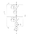
- FIG. 3 illustrates generally an example front-end amplifier 300 employing a transconductor 317 and current attenuator 318 in the feedback loop 304.
- the front-end amplifier 300 can include a three stage amplifier 319 having a transfer function that includes two poles and one zero.
- the front-end amplifier can be used to process capacitive signals received from a MEMS device, such as a MEMS gyroscope (not shown).
- the use of the transconductor 317 to convert the voltage signal to a current signal can improve performance of the front-end amplifier 300 over the example front end amplifier of FIG.
- the front-end amplifier 300 can include a common mode feedback circuit 320 to stabilize common mode voltages of the differential input of the front-end amplifier 300.
- the common mode feedback circuit 320 can set the common mode voltage to the common mode reference (ref).
- a front-end charge amplifier can provide improved processing performance of the MEMS device sense signals.
- a front-end amplifier having a transfer function including two poles and one zero can reduce signal attenuation and phase shift of the sense signal at or near a frequency of interest, or frequency range of interest, over existing front-end amplifiers employing a single pole transfer function.
- FIGS. 4A and 4B illustrate general comparisons of a single-pole charge amplifier 401 compared to an example front-end charge amplifier 402 having two poles and a single zero.
- an example front-end charge amplifier can provide 100dB DC gain compared to 80dB DC gain of a single pole front-end amplifier, as illustrated in FIG. 4A .
- the plots of FIGS. 4A and 4B are taken from an example front-end charge amplifier having two poles at 20kHz and one zero at 2MHz and a single-pole front-end amplifier having a single pole at 2kHz. It is understood that other pole and zero frequencies are possible, including but not limited to, pole frequencies below or near the resonant frequency of the MEMS device, without departing from the scope of the present subject matter.
- pole and zero frequencies can be selected to provide improved phase and gain stability.
- the pole and zero frequencies can be selected to reduce a noise bandwidth.
- FIG. 4B illustrates comparisons of open loop frequency phase characteristics of the single-pole charge amplifier 401 and an example front-end charge amplifier 402 having two poles and a single zero.
- the example front-end amplifier can reduce the phase shift to about -1.2 millidegrees (mdeg) compared to about -57.3 mdeg for the single-pole front-end amplifier.
- Example 1 con include a charge amplifier configured to couple to a microelectromechanical system (MEMS) device and to provide sense information of a proof mass of the MEMS device, a feedback circuit configured to receive the sense information and to provide feedback to an input of the charge amplifier; and wherein the charge amplifier includes a transfer function having a first pole at a first frequency, a second pole at a second frequency, and one zero at a third frequency.
- MEMS microelectromechanical system
- the charge amplifier includes a transfer function having a first pole at a first frequency, a second pole at a second frequency, and one zero at a third frequency.
- Example 2 the first frequency and the second frequency of Example 1 are at or below a resonance frequency of the proof mass.
- Example 3 the third frequency of any one or more of Examples 1-2 optionally is substantially higher than the first frequency and the second frequency.
- Example 4 the two poles and the zero of any one or more of Examples 1-3 optionally are configured to reduce phase offset of the sense information to substantially zero over a predetermined frequency range.
- Example 5 the charge amplifier of any one or more of Examples 1-4 optionally includes a multistage charge amplifier.
- Example 6 the multistage charge amplifier of any one or more of Examples 1-5 optionally includes a first amplifier stage configured to provide a fixed gain.
- Example 7 the multistage charge amplifier of any one or more of Examples 1-6 optionally includes a second amplifier stage having a transfer function including the first pole.
- a gain of the second amplifier stageof any one or more of Examples 1-7 optionally is a variable gain.
- Example 9 the multistage charge amplifier of any one or more of Examples 1-8 optionally includes a third amplifier stage having a transfer function including the second pole and the zero.
- Example 10 the feedback circuit of any one or more of Examples 1-9 optionally includes an adjustable capacitance.
- the feedback circuit of any one or more of Examples 1-10 optionally includes a resistor network, the resistor network including a current mirror coupled to the input of the charge amplifier; a first feedback resistor coupled to an output of the charge amplifier and coupled in series with the current mirror to the input of the charge amplifier, and a second feedback resistor having a first terminal coupled to a voltage supply and a second terminal coupled to the current mirror and the first feedback resistor.
- Example 12 the feedback circuit of any one or more of Examples 1-11 optionally includes a current attenuator coupled to the input of the charge amplifier, and a transconductor coupled to the current attenuator and an output of the charge amplifier, the transconductor configured provide a current signal representative of the sense information.
- a method can include receiving a sense signal from a microelectromechanical system (MEMS) device, and providing a voltage representative of a capacitance of the MEMS device using the sense signal and an amplifier having a first transfer function pole at a first frequency, a second transfer function pole at a second frequency, and one transfer function zero at a third frequency.
- MEMS microelectromechanical system
- Example 14 the receiving a sense signal of any one or more of Examples 1-13 optionally includes receiving a sense signal associated with a proof mass of the MEMS device, and wherein the first frequency and the second frequency are below or about equal to a resonance frequency of the proof mass.
- Example 15 the providing a voltage representative of the capacitance of any one or more of Examples 1-14 optionally includes providing substantially zero phase offset over a predetermined frequency range between the sense signal and the voltage using the two transfer function poles and the transfer function zero.
- Example 16 the method of any one or more of Examples 1-15 optionally includes providing first feedback to an input of the amplifier using an adjustable capacitance coupled to an output of the amplifier.
- Example 17 the method of any one or more of Examples 1-16 optionally includes providing second feedback to the input of the amplifier using a current signal representative of the sense information.
- Example 18 the providing the second feedback of any one or more of Examples 1-17 optionally includes converting the sense information from a voltage signal to a current signal using a transconductor, and attenuating the current signal using a current attenuator to provide the second feedback to the input.
- a system can include a microelectromechanical system (MEMS) sensor, and a front-end charge amplifier configured to provide sense information of the MEMS sensor.
- the front-end charge amplifier can include a charge amplifier configured to couple to the MEMS sensor and to provide the sense information of a proof mass of the MEMS sensor, a feedback circuit configured to receive the sense information and to provide feedback to an input of the charge amplifier, and wherein the charge amplifier includes a transfer function having a first pole at a first frequency, a second pole at a second frequency, and one zero at a third frequency.
- Example 20 the MEMS sensor of any one or more of Examples 1-19 optionally includes a MEMS gyroscope.
- Method examples described herein can be machine or computer-implemented at least in part. Some examples can include a computer-readable medium or machine-readable medium encoded with instructions operable to configure an electronic device to perform methods as described in the above examples.
- An implementation of such methods can include code, such as microcode, assembly language code, a higher-level language code, or the like. Such code can include computer readable instructions for performing various methods. The code may form portions of computer program products. Further, in an example, the code can be tangibly stored on one or more volatile, non-transitory, or non-volatile tangible computer-readable media, such as during execution or at other times.
- Examples of these tangible computer-readable media can include, but are not limited to, hard disks, removable magnetic disks, removable optical disks (e.g., compact disks and digital video disks), magnetic cassettes, memory cards or sticks, random access memories (RAMs), read only memories (ROMs), and the like.
Landscapes
- Engineering & Computer Science (AREA)
- Power Engineering (AREA)
- Signal Processing (AREA)
- Physics & Mathematics (AREA)
- General Physics & Mathematics (AREA)
- Radar, Positioning & Navigation (AREA)
- Remote Sensing (AREA)
- Gyroscopes (AREA)
- Micromachines (AREA)
- Amplifiers (AREA)
Abstract
Description
- This application claims the benefit of priority to
Opris et al., U.S. Provisional Patent Application Serial Number, 61/620,622 - This document discusses, among other things, apparatus and methods for a front-end charge amplifier. In certain examples, a front-end charge amplifier for a microelectromechanical system (MEMS) device can include a charge amplifier configured to couple to the MEMS device and to provide sense information of a proof mass of the MEMS device, a feedback circuit configured to receive the sense information and to provide feedback to an input of the charge amplifier, and wherein the charge amplifier includes a transfer function having a first pole at a first frequency, a second pole at a second frequency, and one zero at a third frequency.
- This overview is intended to provide a general overview of subject matter of the present patent application. It is not intended to provide an exclusive or exhaustive explanation of the invention. The detailed description is included to provide further information about the present patent application.
- In the drawings, which are not necessarily drawn to scale, like numerals may describe similar components in different views. Like numerals having different letter suffixes may represent different instances of similar components. The drawings illustrate generally, by way of example, but not by way of limitation, various embodiments discussed in the present document.
-
FIG. 1 illustrates generally an example front-end amplifier. -
FIG. 2 illustrates generally example amplifier stages of an example front-end amplifier. -
FIG. 3 illustrates generally an example front-end amplifier employing a transconductor and current attenuator in the feedback loop. -
FIGS. 4A and 4B illustrate general comparisons of a single-pole charge amplifier and an example front-end charge amplifier having two poles and a single zero - The present inventors have recognized an improved front-end amplifier for use with microelectromechanical system (MEMS) device such as a MEMS gyroscope. The front end amplifiers can convert charge from MEMS device electrodes to voltage for further processing to assist in providing feedback for driving the MEMS device or to assist in sensing movement of the MEMS device. The improved front-end amplifiers can reduce noise, reduce distortion, reduce offset, and provide improved temperature stability of gain drift and phase drift over existing amplifiers that convert charge from capacitive MEMS sensors to voltage.
-
FIG. 1 illustrates generally an example front-end amplifier 100. In certain examples, the front-end amplifier 100 can be used to convert charge of a capacitive MEMS device sensor to voltage to assist in driving aproof mass 102 of a MEMS device such as aMEMS gyroscope 101, for example, or to assist in providing an indication of movement of theMEMS gyroscope 101. In certain examples, the front-end amplifier 100 can receive a differential sense signal from a pair ofcapacitive sensor electrodes 103 of theMEMS gyroscope 101, and can provide a differential voltage (VOUT) that is representative of the charge on thecapacitive sensor electrodes 103. In certain examples, thecapacitive sensor electrodes 103 can be associated with a proof mass of the MEMS device and the sense signal can provide sense information about position and movement of the proof mass. - In an example, the front-
end amplifier 100 can include afeedback loop 104 coupled between the input of the front-end amplifier 100 and the output of the front-end amplifier 100. In certain examples, thefeedback loop 104 can include an adjustable capacitance (CF) such as an adjustable capacitor. In an example, thefeedback loop 104 can include aresistor network 105 and a current-basedreference resistor 106 that can include acurrent mirror 107. In certain examples, theresistor network 105 and current-basedreference resistor 106 can be coupled in parallel with the adjustable capacitance (CF). In certain examples, the overall gain of the front-end amplifier 100 can be set using the adjustable capacitance (CF). In an example, the value of current supplied by the current-basedreference resistor 106 can also change with the adjustable capacitance (CF) such that closed loop pole locations of the front-end amplifier 100 do not change, thereby preserving phase relationship at a predetermined frequency or frequency range such as the resonant frequency of theMEMS gyroscope 101. In certain examples, the front-end amplifier 100 can include multiple amplifier stages, such as afirst stage 108, asecond stage 109, and athird stage 110. -
FIG. 2 illustrates generally example amplifier stages of an example multistage front-end charge amplifier 200. In certain examples, the multistage front-end amplifier 200 can include afirst amplifier stage 208, asecond amplifier stage 209, and athird amplifier stage 210. In some examples, a transfer function of the threeamplifier stages first amplifier stage 208 can provide a straight, or fixed, gain with low noise. In an example, the gain of thefirst amplifier stage 208 can be about 10. In certain examples, thesecond amplifier stage 209 can provide a transfer function including a pole. In some examples, thesecond amplifier stage 209 can include a variable gain configured to accommodate loop gain factors and the ensure feedback loop stability. In an example, thesecond amplifier stage 209 can have a gain of about 25 micro-amps per volt (uA/V) to about 250 uA/V. In an example, thesecond amplifier stage 209 can include anamplifier 212 with a feedback loop with acapacitive element 211. It is understood that the gains provided above are example gains and that other gains are possible without departing from the scope of the present subject matter. Thethird amplifier stage 210 can provide a transfer function including a pole and one zero. In an example, thethird amplifier stage 210 can include anamplifier 214 with a firstcapacitive element 215 in a feedback loop, and a secondcapacitive element 216 coupled to the input of thethird amplifier stage 210 and configured to receive the input signal to thethird amplifier stage 210. In certain examples, the secondcapacitive element 216 can be coupled to the input signal of thethird amplifier stage 210 through a resistive element. In an example, thethird amplifier stage 210 can receive the output of thesecond amplifier stage 209, and the second amplifier stage can receive the output of thefirst amplifier stage 208. It is understood that different sequential arrangements of the amplifier stages, including different sequential arrangements of the amplifier stages including the poles and the zero, are possible without departing from the scope of the present subject matter. It is understood that a front-end amplifier can include more or less amplifier stages without departing from the scope of the present subject matter. - In addition to the above improvements, the example front-end amplifier can provide low Δgain/gain drift versus temperature (40dB additional open loop gain). In certain examples, the front-end amplifier can provide low variation of Δphase drift versus temperature (5-50 times improvement over a single pole front-end amplifier). In certain examples, the front-end amplifier can provide low output offset. In some examples, the multistage front-
end charge amplifier 200 can provide at least 60dB of gain, a high pass filter corner at ∼2Hz, and a closed loop bandwidth up to 20MHz, to allow phase at 20kHz to not drift much due to RC variation vs. temperature. Gain of each stage in the multistage front-end charge amplifier 200 can be set by a ratio of resistors to provide constant gain vs. temp. -
FIG. 3 illustrates generally an example front-end amplifier 300 employing atransconductor 317 andcurrent attenuator 318 in thefeedback loop 304. The front-end amplifier 300 can include a threestage amplifier 319 having a transfer function that includes two poles and one zero. The front-end amplifier can be used to process capacitive signals received from a MEMS device, such as a MEMS gyroscope (not shown). The use of thetransconductor 317 to convert the voltage signal to a current signal can improve performance of the front-end amplifier 300 over the example front end amplifier ofFIG. 1 because the current basedreference resistor 106 can distort an input signal non-linearly whereas thetransconductor 317 does not distort the sensor signal in a non-linear fashion near the frequency of interest. In certain examples, the front-end amplifier 300 can include a commonmode feedback circuit 320 to stabilize common mode voltages of the differential input of the front-end amplifier 300. In some examples, the commonmode feedback circuit 320 can set the common mode voltage to the common mode reference (ref). - In certain examples, a front-end charge amplifier according to the present subject matter can provide improved processing performance of the MEMS device sense signals. For example, a front-end amplifier having a transfer function including two poles and one zero can reduce signal attenuation and phase shift of the sense signal at or near a frequency of interest, or frequency range of interest, over existing front-end amplifiers employing a single pole transfer function.
FIGS. 4A and 4B illustrate general comparisons of a single-pole charge amplifier 401 compared to an example front-end charge amplifier 402 having two poles and a single zero. In an example, such as with a MEMS gyroscope having a gyroscope resonant frequency at about 20kHz, an example front-end charge amplifier can provide 100dB DC gain compared to 80dB DC gain of a single pole front-end amplifier, as illustrated inFIG. 4A . The plots ofFIGS. 4A and 4B are taken from an example front-end charge amplifier having two poles at 20kHz and one zero at 2MHz and a single-pole front-end amplifier having a single pole at 2kHz. It is understood that other pole and zero frequencies are possible, including but not limited to, pole frequencies below or near the resonant frequency of the MEMS device, without departing from the scope of the present subject matter. In certain examples, such pole and zero frequencies can be selected to provide improved phase and gain stability. In some examples, the pole and zero frequencies can be selected to reduce a noise bandwidth.FIG. 4B illustrates comparisons of open loop frequency phase characteristics of the single-pole charge amplifier 401 and an example front-end charge amplifier 402 having two poles and a single zero. With respect to phase shift, the example front-end amplifier can reduce the phase shift to about -1.2 millidegrees (mdeg) compared to about -57.3 mdeg for the single-pole front-end amplifier. - In Example 1, and apparatus con include a charge amplifier configured to couple to a microelectromechanical system (MEMS) device and to provide sense information of a proof mass of the MEMS device, a feedback circuit configured to receive the sense information and to provide feedback to an input of the charge amplifier; and wherein the charge amplifier includes a transfer function having a first pole at a first frequency, a second pole at a second frequency, and one zero at a third frequency.
- In Example 2, the first frequency and the second frequency of Example 1 are at or below a resonance frequency of the proof mass.
- In Example 3, the third frequency of any one or more of Examples 1-2 optionally is substantially higher than the first frequency and the second frequency.
- In Example 4, the two poles and the zero of any one or more of Examples 1-3 optionally are configured to reduce phase offset of the sense information to substantially zero over a predetermined frequency range.
- In Example 5, the charge amplifier of any one or more of Examples 1-4 optionally includes a multistage charge amplifier.
- In Example 6, the multistage charge amplifier of any one or more of Examples 1-5 optionally includes a first amplifier stage configured to provide a fixed gain.
- In Example 7, the multistage charge amplifier of any one or more of Examples 1-6 optionally includes a second amplifier stage having a transfer function including the first pole.
- In Example 8, a gain of the second amplifier stageof any one or more of Examples 1-7 optionally is a variable gain.
- In Example 9, the multistage charge amplifier of any one or more of Examples 1-8 optionally includes a third amplifier stage having a transfer function including the second pole and the zero.
- In Example 10, the feedback circuit of any one or more of Examples 1-9 optionally includes an adjustable capacitance.
- In Example 11, the feedback circuit of any one or more of Examples 1-10 optionally includes a resistor network, the resistor network including a current mirror coupled to the input of the charge amplifier; a first feedback resistor coupled to an output of the charge amplifier and coupled in series with the current mirror to the input of the charge amplifier, and a second feedback resistor having a first terminal coupled to a voltage supply and a second terminal coupled to the current mirror and the first feedback resistor.
- In Example 12, the feedback circuit of any one or more of Examples 1-11 optionally includes a current attenuator coupled to the input of the charge amplifier, and a transconductor coupled to the current attenuator and an output of the charge amplifier, the transconductor configured provide a current signal representative of the sense information.
- In Example 13, a method can include receiving a sense signal from a microelectromechanical system (MEMS) device, and providing a voltage representative of a capacitance of the MEMS device using the sense signal and an amplifier having a first transfer function pole at a first frequency, a second transfer function pole at a second frequency, and one transfer function zero at a third frequency.
- In Example 14, the receiving a sense signal of any one or more of Examples 1-13 optionally includes receiving a sense signal associated with a proof mass of the MEMS device, and wherein the first frequency and the second frequency are below or about equal to a resonance frequency of the proof mass.
- In Example 15, the providing a voltage representative of the capacitance of any one or more of Examples 1-14 optionally includes providing substantially zero phase offset over a predetermined frequency range between the sense signal and the voltage using the two transfer function poles and the transfer function zero.
- In Example 16, the method of any one or more of Examples 1-15 optionally includes providing first feedback to an input of the amplifier using an adjustable capacitance coupled to an output of the amplifier.
- In Example 17, the method of any one or more of Examples 1-16 optionally includes providing second feedback to the input of the amplifier using a current signal representative of the sense information.
- In Example 18, the providing the second feedback of any one or more of Examples 1-17 optionally includes converting the sense information from a voltage signal to a current signal using a transconductor, and attenuating the current signal using a current attenuator to provide the second feedback to the input.
- In Example 19, a system can include a microelectromechanical system (MEMS) sensor, and a front-end charge amplifier configured to provide sense information of the MEMS sensor. The front-end charge amplifier can include a charge amplifier configured to couple to the MEMS sensor and to provide the sense information of a proof mass of the MEMS sensor, a feedback circuit configured to receive the sense information and to provide feedback to an input of the charge amplifier, and wherein the charge amplifier includes a transfer function having a first pole at a first frequency, a second pole at a second frequency, and one zero at a third frequency.
- In Example 20, the MEMS sensor of any one or more of Examples 1-19 optionally includes a MEMS gyroscope.
- The above detailed description includes references to the accompanying drawings, which form a part of the detailed description. The drawings show, by way of illustration, specific embodiments in which the invention can be practiced. These embodiments are also referred to herein as "examples." Such examples can include elements in addition to those shown or described. However, the present inventors also contemplate examples in which only those elements shown or described are provided. Moreover, the present inventors also contemplate examples using any combination or permutation of those elements shown or described (or one or more aspects thereof), either with respect to a particular example (or one or more aspects thereof), or with respect to other examples (or one or more aspects thereof) shown or described herein.
- All publications, patents, and patent documents referred to in this document are incorporated by reference herein in their entirety, as though individually incorporated by reference. In the event of inconsistent usages between this document and those documents so incorporated by reference, the usage in the incorporated reference(s) should be considered supplementary to that of this document; for irreconcilable inconsistencies, the usage in this document controls.
- In this document, the terms "a" or "an" are used, as is common in patent documents, to include one or more than one, independent of any other instances or usages of "at least one" or "one or more." In this document, the term "or" is used to refer to a nonexclusive or, such that "A or B" includes "A but not B," "B but not A," and "A and B," unless otherwise indicated. In this document, the terms "including" and "in which" are used as the plain-English equivalents of the respective terms "comprising" and "wherein." Also, in the following claims, the terms "including" and "comprising" are open-ended, that is, a system, device, article, or process that includes elements in addition to those listed after such a term in a claim are still deemed to fall within the scope of that claim. Moreover, in the following claims, the terms "first," "second," and "third," etc. are used merely as labels, and are not intended to impose numerical requirements on their objects.
- Method examples described herein can be machine or computer-implemented at least in part. Some examples can include a computer-readable medium or machine-readable medium encoded with instructions operable to configure an electronic device to perform methods as described in the above examples. An implementation of such methods can include code, such as microcode, assembly language code, a higher-level language code, or the like. Such code can include computer readable instructions for performing various methods. The code may form portions of computer program products. Further, in an example, the code can be tangibly stored on one or more volatile, non-transitory, or non-volatile tangible computer-readable media, such as during execution or at other times. Examples of these tangible computer-readable media can include, but are not limited to, hard disks, removable magnetic disks, removable optical disks (e.g., compact disks and digital video disks), magnetic cassettes, memory cards or sticks, random access memories (RAMs), read only memories (ROMs), and the like.
- The above description is intended to be illustrative, and not restrictive. For example, the above-described examples (or one or more aspects thereof) may be used in combination with each other. Other embodiments can be used, such as by one of ordinary skill in the art upon reviewing the above description. The Abstract is provided to comply with 37 C.F.R. §1.72(b), to allow the reader to quickly ascertain the nature of the technical disclosure. It is submitted with the understanding that it will not be used to interpret or limit the scope or meaning of the claims. Also, in the above Detailed Description, various features may be grouped together to streamline the disclosure. This should not be interpreted as intending that an unclaimed disclosed feature is essential to any claim. Rather, inventive subject matter may lie in less than all features of a particular disclosed embodiment. Thus, the following claims are hereby incorporated into the Detailed Description, with each claim standing on its own as a separate embodiment, and it is contemplated that such embodiments can be combined with each other in various combinations or permutations. The scope of the invention should be determined with reference to the appended claims, along with the full scope of equivalents to which such claims are entitled.
Claims (15)
- An apparatus comprising:a charge amplifier configured to couple to a microelectromechanical system (MEMS) device and to provide sense information of a proof mass of the MEMS device;a feedback circuit configured to receive the sense information and to provide feedback to an input of the charge amplifier; andwherein the charge amplifier includes a transfer function having a first pole at a first frequency, a second pole at a second frequency, and one zero at a third frequency.
- The apparatus of claim 1, wherein the first frequency and the second frequency are at or below a resonance frequency of the proof mass.
- The apparatus of claim 1, wherein the third frequency is substantially higher than the first frequency and the second frequency.
- The apparatus of claim 1, wherein the charge amplifier include a multistage charge amplifier, and wherein the multistage charge amplifier includes a first amplifier stage configured to provide a fixed gain.
- The apparatus of claim 4, wherein the multistage charge amplifier includes a second amplifier stage having a transfer function including the first pole, and wherein a gain of the second amplifier stage is a variable gain.
- The apparatus of claim 5, wherein the multistage charge amplifier includes a third amplifier stage having a transfer function including the second pole and the zero.
- The apparatus of claim 1, wherein the feedback circuit includes an adjustable capacitance.
- The apparatus of claim 1, wherein the feedback circuit includes a resistor network, the resistor network including:a current mirror coupled to the input of the charge amplifiera first feedback resistor coupled to an output of the charge amplifier and coupled in series with the current mirror to the input of the charge amplifier; anda second feedback resistor having a first terminal coupled to a voltage supply and a second terminal coupled to the current mirror and the first feedback resistor.
- The apparatus of claim 1, wherein the feedback circuit includes;
a current attenuator coupled to the input of the charge amplifier; and
a transconductor coupled to the current attenuator and an output of the charge amplifier, the transconductor configured provide a current signal representative of the sense information. - A method comprising:receiving a sense signal from a microelectromechanical system (MEMS) device; andproviding a voltage representative of a capacitance of the MEMS device using the sense signal and an amplifier having a first transfer function pole at a first frequency, a second transfer function pole at a second frequency, and one transfer function zero at a third frequency.
- The method of claim 10, wherein the receiving a sense signal includes receiving a sense signal associated with a proof mass of the MEMS device; and
wherein the first frequency and the second frequency are below or about equal to a resonance frequency of the proof mass. - The method of claim 10, including providing first feedback to an input of the amplifier using an adjustable capacitance coupled to an output of the amplifier.
- The method of claim 12, including providing second feedback to the input of the amplifier using a current signal representative of the sense information.
- The method of claim 13, wherein the providing the second feedback includes:converting the sense information from a voltage signal to a current signal using a transconductor; andattenuating the current signal using a current attenuator to provide the second feedback to the input.
- A system comprising:a microelectromechanical system (MEMS) sensor; anda front-end charge amplifier configured to provide sense information of the MEMS sensor, the front-end charge amplifier comprising:a charge amplifier configured to couple to the MEMS sensor and to provide the sense information of a proof mass of the MEMS sensor;a feedback circuit configured to receive the sense information and to provide feedback to an input of the charge amplifier; andwherein the charge amplifier includes a transfer function having a first pole at a first frequency, a second pole at a second frequency, and one zero at a third frequency.
Applications Claiming Priority (1)
| Application Number | Priority Date | Filing Date | Title |
|---|---|---|---|
| US201261620622P | 2012-04-05 | 2012-04-05 |
Publications (2)
| Publication Number | Publication Date |
|---|---|
| EP2648334A1 true EP2648334A1 (en) | 2013-10-09 |
| EP2648334B1 EP2648334B1 (en) | 2020-06-10 |
Family
ID=48045250
Family Applications (1)
| Application Number | Title | Priority Date | Filing Date |
|---|---|---|---|
| EP13001721.3A Active EP2648334B1 (en) | 2012-04-05 | 2013-04-04 | Mems device front-end charge amplifier |
Country Status (4)
| Country | Link |
|---|---|
| US (1) | US9444404B2 (en) |
| EP (1) | EP2648334B1 (en) |
| KR (1) | KR102058489B1 (en) |
| CN (3) | CN203368406U (en) |
Cited By (2)
| Publication number | Priority date | Publication date | Assignee | Title |
|---|---|---|---|---|
| WO2017019288A1 (en) * | 2015-07-29 | 2017-02-02 | Qualcomm Incorporated | Swing limiter circuit |
| ITUB20159233A1 (en) * | 2015-12-23 | 2017-06-23 | St Microelectronics Srl | ELECTRONIC AMPLIFICATION CIRCUIT WITH REDUCED START-UP TIME FOR A SIGNAL INCLUDING COMPONENTS IN SQUARE |
Families Citing this family (27)
| Publication number | Priority date | Publication date | Assignee | Title |
|---|---|---|---|---|
| US8739626B2 (en) | 2009-08-04 | 2014-06-03 | Fairchild Semiconductor Corporation | Micromachined inertial sensor devices |
| CN103221331B (en) | 2010-09-18 | 2016-02-03 | 快捷半导体公司 | Hermetically sealed for MEMS |
| DE112011103124T5 (en) | 2010-09-18 | 2013-12-19 | Fairchild Semiconductor Corporation | Bearing for reducing quadrature for resonant micromechanical devices |
| EP2616772B1 (en) | 2010-09-18 | 2016-06-22 | Fairchild Semiconductor Corporation | Micromachined monolithic 3-axis gyroscope with single drive |
| US8813564B2 (en) | 2010-09-18 | 2014-08-26 | Fairchild Semiconductor Corporation | MEMS multi-axis gyroscope with central suspension and gimbal structure |
| KR101871865B1 (en) | 2010-09-18 | 2018-08-02 | 페어차일드 세미컨덕터 코포레이션 | Multi-die mems package |
| KR101938609B1 (en) | 2010-09-18 | 2019-01-15 | 페어차일드 세미컨덕터 코포레이션 | Micromachined monolithic 6-axis inertial sensor |
| WO2012040245A2 (en) | 2010-09-20 | 2012-03-29 | Fairchild Semiconductor Corporation | Through silicon via with reduced shunt capacitance |
| WO2012040211A2 (en) | 2010-09-20 | 2012-03-29 | Fairchild Semiconductor Corporation | Microelectromechanical pressure sensor including reference capacitor |
| US9062972B2 (en) | 2012-01-31 | 2015-06-23 | Fairchild Semiconductor Corporation | MEMS multi-axis accelerometer electrode structure |
| US8978475B2 (en) | 2012-02-01 | 2015-03-17 | Fairchild Semiconductor Corporation | MEMS proof mass with split z-axis portions |
| US9488693B2 (en) | 2012-04-04 | 2016-11-08 | Fairchild Semiconductor Corporation | Self test of MEMS accelerometer with ASICS integrated capacitors |
| EP2647955B8 (en) | 2012-04-05 | 2018-12-19 | Fairchild Semiconductor Corporation | MEMS device quadrature phase shift cancellation |
| US9069006B2 (en) | 2012-04-05 | 2015-06-30 | Fairchild Semiconductor Corporation | Self test of MEMS gyroscope with ASICs integrated capacitors |
| EP2647952B1 (en) | 2012-04-05 | 2017-11-15 | Fairchild Semiconductor Corporation | Mems device automatic-gain control loop for mechanical amplitude drive |
| KR102058489B1 (en) | 2012-04-05 | 2019-12-23 | 페어차일드 세미컨덕터 코포레이션 | Mems device front-end charge amplifier |
| KR101999745B1 (en) | 2012-04-12 | 2019-10-01 | 페어차일드 세미컨덕터 코포레이션 | Micro-electro-mechanical-system(mems) driver |
| US9625272B2 (en) | 2012-04-12 | 2017-04-18 | Fairchild Semiconductor Corporation | MEMS quadrature cancellation and signal demodulation |
| DE102013014881B4 (en) | 2012-09-12 | 2023-05-04 | Fairchild Semiconductor Corporation | Enhanced silicon via with multi-material fill |
| US9644963B2 (en) | 2013-03-15 | 2017-05-09 | Fairchild Semiconductor Corporation | Apparatus and methods for PLL-based gyroscope gain control, quadrature cancellation and demodulation |
| CN104348431B (en) | 2013-07-31 | 2017-04-26 | 快捷半导体(苏州)有限公司 | Common-mode feedback differential amplification circuit, method and integrated circuit |
| DE102013217102B4 (en) * | 2013-08-28 | 2023-03-16 | Robert Bosch Gmbh | Controller for controlling a micromechanical actuator, control system for controlling a micromechanical actuator, micromirror system and method for controlling a micromechanical actuator |
| CN104883134B (en) * | 2014-02-27 | 2018-11-27 | 无锡华润上华科技有限公司 | A kind of gyroscope pre-amplification circuit and electronic device |
| US9835647B2 (en) | 2014-03-18 | 2017-12-05 | Fairchild Semiconductor Corporation | Apparatus and method for extending analog front end sense range of a high-Q MEMS sensor |
| GB2588557B (en) * | 2017-03-31 | 2021-09-15 | Cirrus Logic Int Semiconductor Ltd | MEMS transducer system and associated methods |
| US11009350B2 (en) * | 2018-01-11 | 2021-05-18 | Invensense, Inc. | Proof mass offset compensation |
| KR102160673B1 (en) * | 2020-01-13 | 2020-09-29 | 서울대학교산학협력단 | Current-reuse low power instrumentation amplifier and fully differential differential amplifiers included therein |
Citations (2)
| Publication number | Priority date | Publication date | Assignee | Title |
|---|---|---|---|---|
| US7305880B2 (en) * | 2004-08-03 | 2007-12-11 | Stmicroelectronics S.R.L. | Resonant micro-electro-mechanical system with analog driving |
| EP2259019A1 (en) * | 2009-06-03 | 2010-12-08 | STMicroelectronics S.r.l. | Microelectromechanical gyroscope with position control driving and method for controlling a microelectromechanical gyroscope |
Family Cites Families (310)
| Publication number | Priority date | Publication date | Assignee | Title |
|---|---|---|---|---|
| US3231729A (en) | 1961-03-31 | 1966-01-25 | Systems Inc Comp | Dynamic storage analog computer |
| US4511848A (en) | 1983-06-15 | 1985-04-16 | Watson Industries, Inc. | Synchronous AM demodulator with quadrature signal cancellation |
| US5354695A (en) | 1992-04-08 | 1994-10-11 | Leedy Glenn J | Membrane dielectric isolation IC fabrication |
| US4896156A (en) | 1988-10-03 | 1990-01-23 | General Electric Company | Switched-capacitance coupling networks for differential-input amplifiers, not requiring balanced input signals |
| TW520072U (en) | 1991-07-08 | 2003-02-01 | Samsung Electronics Co Ltd | A semiconductor device having a multi-layer metal contact |
| DE4142101A1 (en) | 1991-11-28 | 1993-06-03 | Lueder Ernst Prof Dr Ing | PRESSURE MEASUREMENT ARRAY WITH HIGH LINEARITY |
| EP0547742B1 (en) | 1991-12-19 | 1995-12-13 | Motorola, Inc. | Triaxial accelerometer |
| US5491604A (en) | 1992-12-11 | 1996-02-13 | The Regents Of The University Of California | Q-controlled microresonators and tunable electronic filters using such resonators |
| FR2700003B1 (en) | 1992-12-28 | 1995-02-10 | Commissariat Energie Atomique | Method for manufacturing a pressure sensor using silicon on insulator technology and sensor obtained. |
| WO1995003534A1 (en) | 1993-07-24 | 1995-02-02 | Endress + Hauser Gmbh + Co. | High linearity capacitive pressure sensor |
| US5426970A (en) | 1993-08-02 | 1995-06-27 | New Sd, Inc. | Rotation rate sensor with built in test circuit |
| US5481914A (en) | 1994-03-28 | 1996-01-09 | The Charles Stark Draper Laboratory, Inc. | Electronics for coriolis force and other sensors |
| US5703292A (en) | 1994-03-28 | 1997-12-30 | The Charles Stark Draper Laboratory, Inc. | Sensor having an off-frequency drive scheme and a sense bias generator utilizing tuned circuits |
| US5765046A (en) | 1994-08-31 | 1998-06-09 | Nikon Corporation | Piezoelectric vibration angular velocity meter and camera using the same |
| JPH0989927A (en) | 1995-09-28 | 1997-04-04 | Zexel Corp | Multi-axial acceleration sensor |
| SE9500729L (en) | 1995-02-27 | 1996-08-28 | Gert Andersson | Apparatus for measuring angular velocity in single crystalline material and method for making such |
| US5656778A (en) | 1995-04-24 | 1997-08-12 | Kearfott Guidance And Navigation Corporation | Micromachined acceleration and coriolis sensor |
| US5659195A (en) | 1995-06-08 | 1997-08-19 | The Regents Of The University Of California | CMOS integrated microsensor with a precision measurement circuit |
| US5760465A (en) | 1996-02-01 | 1998-06-02 | International Business Machines Corporation | Electronic package with strain relief means |
| JP3125675B2 (en) | 1996-03-29 | 2001-01-22 | 三菱電機株式会社 | Capacitive sensor interface circuit |
| JPH09318649A (en) | 1996-05-30 | 1997-12-12 | Texas Instr Japan Ltd | Composite sensor |
| JPH10239347A (en) | 1997-02-28 | 1998-09-11 | Japan Aviation Electron Ind Ltd | Motion sensor |
| EP0871213A3 (en) | 1997-03-27 | 1999-03-03 | Siemens Aktiengesellschaft | Method for producing vias having variable sidewall profile |
| JP3050161B2 (en) | 1997-04-18 | 2000-06-12 | 日本電気株式会社 | Semiconductor device and manufacturing method thereof |
| CN1206110A (en) | 1997-07-14 | 1999-01-27 | 利顿系统有限公司 | Signal processing system for inertial sensor |
| KR100326878B1 (en) * | 1997-08-05 | 2002-05-09 | 니시무로 타이죠 | Amplification circuit |
| JPH11352143A (en) | 1998-04-06 | 1999-12-24 | Matsushita Electric Ind Co Ltd | Acceleration sensor |
| US6253612B1 (en) | 1998-06-05 | 2001-07-03 | Integrated Micro Instruments, Inc. | Generation of mechanical oscillation applicable to vibratory rate gyroscopes |
| JP3882972B2 (en) | 1998-06-18 | 2007-02-21 | アイシン精機株式会社 | Angular velocity sensor |
| JP3882973B2 (en) | 1998-06-22 | 2007-02-21 | アイシン精機株式会社 | Angular velocity sensor |
| WO2000003476A1 (en) * | 1998-07-13 | 2000-01-20 | Steensgaard Madsen Jesper | Wide-bandwidth operational amplifier |
| JP2000046560A (en) | 1998-07-31 | 2000-02-18 | Aisin Seiki Co Ltd | Angular velocity sensor |
| US6236096B1 (en) | 1998-10-06 | 2001-05-22 | National Science Council Of Republic Of China | Structure of a three-electrode capacitive pressure sensor |
| US6351996B1 (en) | 1998-11-12 | 2002-03-05 | Maxim Integrated Products, Inc. | Hermetic packaging for semiconductor pressure sensors |
| JP3363862B2 (en) | 1999-01-22 | 2003-01-08 | キヤノン株式会社 | Gyro, camera, lens and automobile having the same |
| DE19910415B4 (en) | 1999-03-10 | 2010-12-09 | Robert Bosch Gmbh | Method and device for tuning a first oscillator with a second oscillator |
| DE60041472D1 (en) | 1999-05-28 | 2009-03-19 | Alps Electric Co Ltd | Excitation device of a piezoelectric vibrator |
| US7051590B1 (en) | 1999-06-15 | 2006-05-30 | Analog Devices Imi, Inc. | Structure for attenuation or cancellation of quadrature error |
| US6516651B1 (en) | 1999-07-22 | 2003-02-11 | Analog Devices, Inc. | Coriolis effect transducer |
| US6522762B1 (en) | 1999-09-07 | 2003-02-18 | Microtronic A/S | Silicon-based sensor system |
| US6230566B1 (en) | 1999-10-01 | 2001-05-15 | The Regents Of The University Of California | Micromachined low frequency rocking accelerometer with capacitive pickoff |
| US6301965B1 (en) | 1999-12-14 | 2001-10-16 | Sandia Corporation | Microelectromechanical accelerometer with resonance-cancelling control circuit including an idle state |
| IT1314296B1 (en) | 1999-12-21 | 2002-12-09 | St Microelectronics Srl | RESISTIVE STRUCTURE INTEGRATED ON A SEMICONDUCTIVE SUBSTRATE |
| US6390905B1 (en) | 2000-03-31 | 2002-05-21 | Speedfam-Ipec Corporation | Workpiece carrier with adjustable pressure zones and barriers |
| JP2004506176A (en) | 2000-04-04 | 2004-02-26 | ローズマウント エアロスペイス インコーポレイテッド | 3-axis accelerometer |
| US6366468B1 (en) | 2000-04-28 | 2002-04-02 | Hewlett-Packard Company | Self-aligned common carrier |
| US6214644B1 (en) | 2000-06-30 | 2001-04-10 | Amkor Technology, Inc. | Flip-chip micromachine package fabrication method |
| US6988408B2 (en) | 2000-07-13 | 2006-01-24 | Dong-Il Cho | Surface/bulk micromachined single-crystalline silicon micro-gyroscope |
| US7523537B1 (en) | 2000-07-13 | 2009-04-28 | Custom Sensors & Technologies, Inc. | Method of manufacturing a tuning fork with reduced quadrature errror and symmetrical mass balancing |
| US7083997B2 (en) | 2000-08-03 | 2006-08-01 | Analog Devices, Inc. | Bonded wafer optical MEMS process |
| US6553835B1 (en) | 2000-09-15 | 2003-04-29 | Bei Technologies, Inc. | Inertial rate sensor and method with improved clocking |
| US6501282B1 (en) | 2000-09-29 | 2002-12-31 | Rockwell Automation Technologies, Inc. | Highly sensitive capacitance comparison circuit |
| US7166910B2 (en) | 2000-11-28 | 2007-01-23 | Knowles Electronics Llc | Miniature silicon condenser microphone |
| DE10059775C2 (en) | 2000-12-01 | 2003-11-27 | Hahn Schickard Ges | Method and device for processing analog output signals from capacitive sensors |
| FR2819064B1 (en) * | 2000-12-29 | 2003-04-04 | St Microelectronics Sa | VOLTAGE REGULATOR WITH IMPROVED STABILITY |
| SG106612A1 (en) | 2001-05-29 | 2004-10-29 | Sony Electronics Singapore Pte | A force sensing device |
| US6504385B2 (en) | 2001-05-31 | 2003-01-07 | Hewlett-Pakcard Company | Three-axis motion sensor |
| US6513380B2 (en) | 2001-06-19 | 2003-02-04 | Microsensors, Inc. | MEMS sensor with single central anchor and motion-limiting connection geometry |
| US6683692B2 (en) | 2001-06-21 | 2004-01-27 | Honeywell International | Dither system for motion sensors |
| US20030033850A1 (en) | 2001-08-09 | 2003-02-20 | Challoner A. Dorian | Cloverleaf microgyroscope with electrostatic alignment and tuning |
| US6937479B2 (en) | 2001-08-21 | 2005-08-30 | The Charles Stark Draper Laboratory, Inc. | Sensor isolation system |
| US6598475B2 (en) | 2001-09-20 | 2003-07-29 | Honeywell International Inc. | Micromechanical inertial sensor having increased pickoff resonance damping |
| ATE509254T1 (en) | 2002-02-06 | 2011-05-15 | Analog Devices Inc | MICRO-MADE GYRO |
| US6714070B1 (en) | 2002-02-07 | 2004-03-30 | Bei Technologies, Inc. | Differential charge amplifier with built-in testing for rotation rate sensor |
| US6785117B2 (en) | 2002-03-15 | 2004-08-31 | Denso Corporation | Capacitive device |
| US6725719B2 (en) | 2002-04-17 | 2004-04-27 | Milli Sensor Systems And Actuators, Inc. | MEMS-integrated inertial measurement units on a common substrate |
| US7217588B2 (en) | 2005-01-05 | 2007-05-15 | Sharp Laboratories Of America, Inc. | Integrated MEMS packaging |
| CN1659810B (en) | 2002-04-29 | 2012-04-25 | 三星电子株式会社 | Direct-connect signaling system |
| US6701786B2 (en) | 2002-04-29 | 2004-03-09 | L-3 Communications Corporation | Closed loop analog gyro rate sensor |
| US6992399B2 (en) | 2002-05-24 | 2006-01-31 | Northrop Grumman Corporation | Die connected with integrated circuit component for electrical signal passing therebetween |
| US6915215B2 (en) | 2002-06-25 | 2005-07-05 | The Boeing Company | Integrated low power digital gyro control electronics |
| US6781231B2 (en) | 2002-09-10 | 2004-08-24 | Knowles Electronics Llc | Microelectromechanical system package with environmental and interference shield |
| US6737742B2 (en) | 2002-09-11 | 2004-05-18 | International Business Machines Corporation | Stacked package for integrated circuits |
| US7477529B2 (en) | 2002-11-01 | 2009-01-13 | Honeywell International Inc. | High-voltage power supply |
| US7187735B2 (en) | 2003-01-28 | 2007-03-06 | Raytheon Company | Mixed technology MEMS/SiGe BiCMOS digitalized analog front end with direct RF sampling |
| US20040231420A1 (en) | 2003-02-24 | 2004-11-25 | Huikai Xie | Integrated monolithic tri-axial micromachined accelerometer |
| JP4336946B2 (en) | 2003-03-20 | 2009-09-30 | セイコーエプソン株式会社 | Method and apparatus for measuring rotational angular velocity |
| US6848304B2 (en) | 2003-04-28 | 2005-02-01 | Analog Devices, Inc. | Six degree-of-freedom micro-machined multi-sensor |
| US7005193B2 (en) | 2003-04-29 | 2006-02-28 | Motorola, Inc. | Method of adding mass to MEMS structures |
| JP4123044B2 (en) | 2003-05-13 | 2008-07-23 | ソニー株式会社 | Micromachine and manufacturing method thereof |
| JP2005024310A (en) | 2003-06-30 | 2005-01-27 | Kyocera Kinseki Corp | Inertia sensor |
| US6845670B1 (en) | 2003-07-08 | 2005-01-25 | Freescale Semiconductor, Inc. | Single proof mass, 3 axis MEMS transducer |
| GB0322236D0 (en) | 2003-09-23 | 2003-10-22 | Qinetiq Ltd | Resonant magnetometer device |
| JP2005123591A (en) | 2003-09-25 | 2005-05-12 | Rohm Co Ltd | Semiconductor device and electronic apparatus packaging the same |
| JP4433747B2 (en) | 2003-09-29 | 2010-03-17 | 株式会社村田製作所 | Angular velocity detector |
| JP4645013B2 (en) | 2003-10-03 | 2011-03-09 | パナソニック株式会社 | Acceleration sensor and composite sensor using the same |
| JP2007516746A (en) | 2003-12-11 | 2007-06-28 | プロテウス バイオメディカル インコーポレイテッド | Implantable pressure sensor |
| US7173402B2 (en) * | 2004-02-25 | 2007-02-06 | O2 Micro, Inc. | Low dropout voltage regulator |
| US20050189622A1 (en) | 2004-03-01 | 2005-09-01 | Tessera, Inc. | Packaged acoustic and electromagnetic transducer chips |
| US6912082B1 (en) | 2004-03-11 | 2005-06-28 | Palo Alto Research Center Incorporated | Integrated driver electronics for MEMS device using high voltage thin film transistors |
| JP3875240B2 (en) | 2004-03-31 | 2007-01-31 | 株式会社東芝 | Manufacturing method of electronic parts |
| TWI255341B (en) | 2004-06-10 | 2006-05-21 | Chung Shan Inst Of Science | Miniature accelerator |
| JP4412477B2 (en) | 2004-06-11 | 2010-02-10 | 株式会社デンソー | Vibration type angular velocity sensor |
| CN100368772C (en) | 2004-06-29 | 2008-02-13 | 东南大学 | Method for extracting two-way harmonic wave of condenser type micro-gyroscope responsive signals and extraction apparatus therefor |
| CN100368773C (en) | 2004-06-29 | 2008-02-13 | 东南大学 | Method for extracting one-way harmonic wave of condenser type micro-gyroscope responsive signals and extraction apparatus therefor |
| US7301212B1 (en) | 2004-07-30 | 2007-11-27 | National Semiconductor Corporation | MEMS microphone |
| US7266349B2 (en) | 2004-08-06 | 2007-09-04 | Broadcom Corporation | Multi-mode crystal oscillator |
| US7929714B2 (en) | 2004-08-11 | 2011-04-19 | Qualcomm Incorporated | Integrated audio codec with silicon audio transducer |
| US7421898B2 (en) | 2004-08-16 | 2008-09-09 | The Regents Of The University Of California | Torsional nonresonant z-axis micromachined gyroscope with non-resonant actuation to measure the angular rotation of an object |
| US7170187B2 (en) | 2004-08-31 | 2007-01-30 | International Business Machines Corporation | Low stress conductive polymer bump |
| CN101044684B (en) | 2004-09-17 | 2012-11-14 | 美国亚德诺半导体公司 | Multi-bit continuous-time front-end sigma-delta adc using chopper stabilization |
| JP4353087B2 (en) | 2004-12-01 | 2009-10-28 | 株式会社デンソー | Rotational vibration type angular velocity sensor |
| JP4969822B2 (en) | 2004-12-06 | 2012-07-04 | 株式会社デンソー | Sensor device |
| US7358151B2 (en) | 2004-12-21 | 2008-04-15 | Sony Corporation | Microelectromechanical system microphone fabrication including signal processing circuitry on common substrate |
| US20060169041A1 (en) | 2005-02-02 | 2006-08-03 | Madni Asad M | Combined gyroscope and 2-axis accelerometer |
| DE102005008512B4 (en) | 2005-02-24 | 2016-06-23 | Epcos Ag | Electrical module with a MEMS microphone |
| US20060207327A1 (en) | 2005-03-16 | 2006-09-21 | Zarabadi Seyed R | Linear accelerometer |
| US7442570B2 (en) | 2005-03-18 | 2008-10-28 | Invensence Inc. | Method of fabrication of a AL/GE bonding in a wafer packaging environment and a product produced therefrom |
| US7213458B2 (en) | 2005-03-22 | 2007-05-08 | Honeywell International Inc. | Quadrature reduction in MEMS gyro devices using quad steering voltages |
| US7231824B2 (en) | 2005-03-22 | 2007-06-19 | Honeywell International Inc. | Use of electrodes to cancel lift effects in inertial sensors |
| JP4453587B2 (en) | 2005-03-24 | 2010-04-21 | 株式会社デンソー | Acceleration sensor |
| EP1715580B1 (en) | 2005-03-31 | 2018-11-28 | STMicroelectronics Srl | Device for controlling the resonance frequency of a MEMS resonator |
| US7885423B2 (en) | 2005-04-25 | 2011-02-08 | Analog Devices, Inc. | Support apparatus for microphone diaphragm |
| US20070071268A1 (en) | 2005-08-16 | 2007-03-29 | Analog Devices, Inc. | Packaged microphone with electrically coupled lid |
| US7449355B2 (en) | 2005-04-27 | 2008-11-11 | Robert Bosch Gmbh | Anti-stiction technique for electromechanical systems and electromechanical device employing same |
| EP1882127A2 (en) | 2005-05-18 | 2008-01-30 | Kolo Technologies, Inc. | Micro-electro-mechanical transducers |
| CN101180516B (en) | 2005-05-24 | 2011-09-14 | 独立行政法人宇宙航空研究开发机构 | Gyroscopes |
| WO2006130828A2 (en) * | 2005-06-02 | 2006-12-07 | Georgia Tech Research Corporation | System and method for sensing capacitance change of a capacitive sensor |
| CN101213461B (en) | 2005-06-03 | 2013-01-02 | 辛纳普蒂克斯公司 | Methods and systems for detecting a capacitance using SIGMA-DELTA measurement techniques |
| US7240552B2 (en) | 2005-06-06 | 2007-07-10 | Bei Technologies, Inc. | Torsional rate sensor with momentum balance and mode decoupling |
| JP2007024864A (en) | 2005-06-16 | 2007-02-01 | Mitsubishi Electric Corp | Oscillating gyroscope |
| JP5128470B2 (en) | 2005-06-17 | 2013-01-23 | コロ テクノロジーズ インコーポレイテッド | Microelectromechanical transducer with insulation extension |
| FI119299B (en) | 2005-06-17 | 2008-09-30 | Vti Technologies Oy | Method for manufacturing a capacitive accelerometer and a capacitive accelerometer |
| US7202552B2 (en) | 2005-07-15 | 2007-04-10 | Silicon Matrix Pte. Ltd. | MEMS package using flexible substrates, and method thereof |
| JP4740678B2 (en) | 2005-07-27 | 2011-08-03 | Okiセミコンダクタ株式会社 | Semiconductor device |
| CN101238060A (en) | 2005-08-11 | 2008-08-06 | 皇家飞利浦电子股份有限公司 | Method for manufacturing a microelectronic package comprising a silicon MEMS microphone |
| US20070220973A1 (en) | 2005-08-12 | 2007-09-27 | Cenk Acar | Multi-axis micromachined accelerometer and rate sensor |
| US7284430B2 (en) | 2005-08-15 | 2007-10-23 | The Regents Of The University Of California | Robust micromachined gyroscopes with two degrees of freedom sense-mode oscillator |
| US20070040231A1 (en) | 2005-08-16 | 2007-02-22 | Harney Kieran P | Partially etched leadframe packages having different top and bottom topologies |
| US7932182B2 (en) | 2005-08-19 | 2011-04-26 | Honeywell International Inc. | Creating novel structures using deep trenching of oriented silicon substrates |
| US8130979B2 (en) | 2005-08-23 | 2012-03-06 | Analog Devices, Inc. | Noise mitigating microphone system and method |
| US7622782B2 (en) | 2005-08-24 | 2009-11-24 | General Electric Company | Pressure sensors and methods of making the same |
| EP1938345B1 (en) | 2005-10-14 | 2009-03-11 | Nxp B.V. | Mems tunable device |
| US7679364B2 (en) | 2005-10-18 | 2010-03-16 | Tursiop Technologies Llc | Method and apparatus for high-gain magnetic resonance imaging |
| JP2009511232A (en) | 2005-10-18 | 2009-03-19 | ターシオップ テクノロジーズ リミテッド ライアビリティ カンパニー | Method and apparatus for high gain nuclear magnetic resonance imaging |
| JP2007114078A (en) | 2005-10-21 | 2007-05-10 | Sony Corp | Drive unit and method for mems sensor, and active sensor using mems sensor |
| US7258011B2 (en) | 2005-11-21 | 2007-08-21 | Invensense Inc. | Multiple axis accelerometer |
| US20070114643A1 (en) | 2005-11-22 | 2007-05-24 | Honeywell International Inc. | Mems flip-chip packaging |
| US7539003B2 (en) | 2005-12-01 | 2009-05-26 | Lv Sensors, Inc. | Capacitive micro-electro-mechanical sensors with single crystal silicon electrodes |
| US7518493B2 (en) | 2005-12-01 | 2009-04-14 | Lv Sensors, Inc. | Integrated tire pressure sensor system |
| EP1793497B1 (en) | 2005-12-02 | 2011-04-27 | STMicroelectronics Srl | Device and method for reading a capacitive sensor, in particular of a micro-electromechanical type |
| US8113050B2 (en) | 2006-01-25 | 2012-02-14 | The Regents Of The University Of California | Robust six degree-of-freedom micromachined gyroscope with anti-phase drive scheme and method of operation of the same |
| US7290435B2 (en) | 2006-02-06 | 2007-11-06 | Invensense Inc. | Method and apparatus for electronic cancellation of quadrature error |
| GB2435544B (en) | 2006-02-24 | 2008-11-19 | Oligon Ltd | Mems device |
| US7436054B2 (en) | 2006-03-03 | 2008-10-14 | Silicon Matrix, Pte. Ltd. | MEMS microphone with a stacked PCB package and method of producing the same |
| CN100451547C (en) | 2006-03-09 | 2009-01-14 | 上海交通大学 | Micro-rotation top with double-stator electromagnetic suspension rotor |
| EP1832841B1 (en) | 2006-03-10 | 2015-12-30 | STMicroelectronics Srl | Microelectromechanical integrated sensor structure with rotary driving motion |
| US7589390B2 (en) | 2006-03-10 | 2009-09-15 | Teledyne Technologies, Incorporated | Shielded through-via |
| DE112007000637T5 (en) | 2006-03-13 | 2009-01-02 | Yishay Sensors Ltd. | 2-axis resonator gyroscope |
| FR2898683B1 (en) | 2006-03-14 | 2008-05-23 | Commissariat Energie Atomique | TRIAXIAL MEMBRANE ACCELEROMETER |
| GB0605576D0 (en) | 2006-03-20 | 2006-04-26 | Oligon Ltd | MEMS device |
| JP2007292499A (en) | 2006-04-21 | 2007-11-08 | Sony Corp | Motion sensor and manufacturing method therefor |
| US7726188B2 (en) | 2006-04-24 | 2010-06-01 | Millisensor Systems + Actuators | Scale factor measurement for mems gyroscopes and accelerometers |
| US7561277B2 (en) | 2006-05-19 | 2009-07-14 | New Jersey Institute Of Technology | MEMS fiber optic microphone |
| JP4310325B2 (en) | 2006-05-24 | 2009-08-05 | 日立金属株式会社 | Angular velocity sensor |
| US7454967B2 (en) | 2006-07-10 | 2008-11-25 | Lv Sensors, Inc. | Signal conditioning methods and circuits for a capacitive sensing integrated tire pressure sensor |
| US7538705B2 (en) | 2006-07-25 | 2009-05-26 | Microchip Technology Incorporated | Offset cancellation and reduced source induced 1/f noise of voltage reference by using bit stream from over-sampling analog-to-digital converter |
| TWI301823B (en) | 2006-08-29 | 2008-10-11 | Ind Tech Res Inst | Package structure and packaging method of mems microphone |
| JP5294228B2 (en) | 2006-09-27 | 2013-09-18 | シチズンホールディングス株式会社 | Physical quantity sensor |
| AU2007302788B2 (en) | 2006-09-28 | 2010-12-16 | Medtronic, Inc. | Capacitive interface circuit for low power sensor system |
| KR100831405B1 (en) | 2006-10-02 | 2008-05-21 | (주) 파이오닉스 | Wafer bonding packaging method |
| US7675162B2 (en) | 2006-10-03 | 2010-03-09 | Innovative Micro Technology | Interconnect structure using through wafer vias and method of fabrication |
| US20080083958A1 (en) | 2006-10-05 | 2008-04-10 | Wen-Chieh Wei | Micro-electromechanical system package |
| DE102006048381A1 (en) | 2006-10-12 | 2008-04-17 | Fraunhofer-Gesellschaft zur Förderung der angewandten Forschung e.V. | Sensor for detecting accelerations |
| US7461552B2 (en) | 2006-10-23 | 2008-12-09 | Custom Sensors & Technologies, Inc. | Dual axis rate sensor |
| US7982570B2 (en) | 2006-11-07 | 2011-07-19 | General Electric Company | High performance low volume inductor and method of making same |
| CN1948906B (en) | 2006-11-10 | 2011-03-23 | 北京大学 | Capacitive type complete decoupling horizontal axis miniature mechanical gyro |
| EP2053413B1 (en) | 2006-11-14 | 2013-05-22 | Panasonic Corporation | Sensor |
| US7403756B1 (en) | 2006-11-22 | 2008-07-22 | Rockwell Collins, Inc. | Highly-integrated MEMS-based miniaturized transceiver |
| US8026771B2 (en) | 2006-11-27 | 2011-09-27 | Seiko Epson Corporation | Driver device, physical quantity measuring device, and electronic instrument |
| TWI315295B (en) | 2006-12-29 | 2009-10-01 | Advanced Semiconductor Eng | Mems microphone module and method thereof |
| US7550828B2 (en) | 2007-01-03 | 2009-06-23 | Stats Chippac, Inc. | Leadframe package for MEMS microphone assembly |
| US8047075B2 (en) | 2007-06-21 | 2011-11-01 | Invensense, Inc. | Vertically integrated 3-axis MEMS accelerometer with electronics |
| US8250921B2 (en) | 2007-07-06 | 2012-08-28 | Invensense, Inc. | Integrated motion processing unit (MPU) with MEMS inertial sensing and embedded digital electronics |
| WO2008087578A2 (en) | 2007-01-17 | 2008-07-24 | Nxp B.V. | A system-in-package with through substrate via holes |
| JP4924370B2 (en) | 2007-01-26 | 2012-04-25 | パナソニック株式会社 | ΣΔ AD converter and angular velocity sensor using the same |
| CN101239697B (en) | 2007-02-06 | 2013-02-13 | 万长风 | Vertical integration microelectron mechanical structure, implementing method and system thereof |
| US7859113B2 (en) | 2007-02-27 | 2010-12-28 | International Business Machines Corporation | Structure including via having refractory metal collar at copper wire and dielectric layer liner-less interface and related method |
| US7950281B2 (en) | 2007-02-28 | 2011-05-31 | Infineon Technologies Ag | Sensor and method for sensing linear acceleration and angular velocity |
| US7544531B1 (en) | 2007-03-13 | 2009-06-09 | Sitime Inc. | Ground strap for suppressing stiction during MEMS fabrication |
| JP2008256438A (en) | 2007-04-03 | 2008-10-23 | Sony Corp | Inertial sensor, and electric/electronic device |
| US20080251866A1 (en) | 2007-04-10 | 2008-10-16 | Honeywell International Inc. | Low-stress hermetic die attach |
| CN101038299A (en) | 2007-04-21 | 2007-09-19 | 中北大学 | Uniaxle integrated inertia measurement device based on single mass-block |
| US8006557B2 (en) | 2007-05-16 | 2011-08-30 | Intellisense Software Corporation | Multi-axis sensor |
| CN100526800C (en) | 2007-05-31 | 2009-08-12 | 上海交通大学 | Flexible static compensation type coil moment-increasing fluid gyroscope |
| CN101316462B (en) | 2007-06-01 | 2012-11-28 | 财团法人工业技术研究院 | Packaging body and packaging component for microphone of micro electro-mechanical systems |
| US8049326B2 (en) | 2007-06-07 | 2011-11-01 | The Regents Of The University Of Michigan | Environment-resistant module, micropackage and methods of manufacturing same |
| CN101067555B (en) | 2007-06-08 | 2010-11-10 | 北京航空航天大学 | Force balancing resonance micro-mechanical gyro |
| US7817331B2 (en) | 2007-06-21 | 2010-10-19 | Jds Uniphase Corporation | MEMS device with an angular vertical comb actuator |
| US8061201B2 (en) | 2007-07-13 | 2011-11-22 | Georgia Tech Research Corporation | Readout method and electronic bandwidth control for a silicon in-plane tuning fork gyroscope |
| DE102007035806B4 (en) | 2007-07-31 | 2011-03-17 | Sensordynamics Ag | Micromechanical rotation rate sensor |
| TWI333933B (en) | 2007-08-17 | 2010-12-01 | Advanced Semiconductor Eng | Microelectromechanical-system package and method for manufacturing the same |
| US20090175477A1 (en) | 2007-08-20 | 2009-07-09 | Yamaha Corporation | Vibration transducer |
| JP5045616B2 (en) | 2007-08-30 | 2012-10-10 | 株式会社デンソー | Capacitive physical quantity detector |
| US8042394B2 (en) | 2007-09-11 | 2011-10-25 | Stmicroelectronics S.R.L. | High sensitivity microelectromechanical sensor with rotary driving motion |
| WO2009038736A2 (en) | 2007-09-19 | 2009-03-26 | Georgia Tech Research Corporation | Single-resonator dual-frequency lateral-extension mode piezoelectric oscillators, and operating methods thereof |
| US7786738B2 (en) | 2007-09-19 | 2010-08-31 | Robert Bosch Gmbh | Cancelling low frequency errors in MEMS systems |
| GB0720412D0 (en) | 2007-10-18 | 2007-11-28 | Melexis Nv | Combined mems accelerometer and gyroscope |
| US7677099B2 (en) | 2007-11-05 | 2010-03-16 | Invensense Inc. | Integrated microelectromechanical systems (MEMS) vibrating mass Z-axis rate sensor |
| JP5487546B2 (en) | 2008-02-18 | 2014-05-07 | パナソニック株式会社 | Angular velocity sensor |
| JP4508230B2 (en) | 2007-11-21 | 2010-07-21 | ソニー株式会社 | Inertial sensor and its detection device |
| CN101459866B (en) | 2007-12-14 | 2016-02-03 | 财团法人工业技术研究院 | Electric microphone module for microcomputer and manufacture method |
| TW200929852A (en) * | 2007-12-25 | 2009-07-01 | Analogtek Corp | A micro-electromechanical capacitive sensing circuit |
| US7830003B2 (en) | 2007-12-27 | 2010-11-09 | Honeywell International, Inc. | Mechanical isolation for MEMS devices |
| CN101217263B (en) | 2008-01-17 | 2010-12-15 | 埃派克森微电子有限公司 | A compensatory method and device for DC offset voltage of amplifier |
| US20090183570A1 (en) | 2008-01-18 | 2009-07-23 | Custom Sensors & Technologies, Inc. | Micromachined cross-differential dual-axis accelerometer |
| US20090194829A1 (en) | 2008-01-31 | 2009-08-06 | Shine Chung | MEMS Packaging Including Integrated Circuit Dies |
| JP2009186213A (en) | 2008-02-04 | 2009-08-20 | Denso Corp | Gyro sensor unit |
| JP5365173B2 (en) | 2008-02-29 | 2013-12-11 | セイコーエプソン株式会社 | Physical quantity measuring device and electronic device |
| CN101270988B (en) | 2008-03-14 | 2011-11-30 | 江苏英特神斯科技有限公司 | Multi-shaft inertial sensor and method for measuring multi-shaft translation and rotation acceleration |
| US7984648B2 (en) | 2008-04-10 | 2011-07-26 | Honeywell International Inc. | Systems and methods for acceleration and rotational determination from an in-plane and out-of-plane MEMS device |
| DE102008002748A1 (en) | 2008-06-27 | 2009-12-31 | Sensordynamics Ag | Microgyroscope |
| TW201004857A (en) | 2008-07-23 | 2010-02-01 | Ind Tech Res Inst | A packaging structure and method for integration of microelectronics and MEMS devices by 3D stacking |
| JP2010025898A (en) | 2008-07-24 | 2010-02-04 | Yamaha Corp | Mems sensor |
| CN101638211A (en) | 2008-08-01 | 2010-02-03 | 财团法人工业技术研究院 | Integrated three-dimensional stacked package structure and manufacturing method thereof |
| US8450817B2 (en) | 2008-08-14 | 2013-05-28 | Knowles Electronics Llc | Microelectromechanical system package with strain relief bridge |
| US8193596B2 (en) | 2008-09-03 | 2012-06-05 | Solid State System Co., Ltd. | Micro-electro-mechanical systems (MEMS) package |
| CN101666813B (en) | 2008-09-05 | 2011-12-21 | 财团法人工业技术研究院 | Multi-axis capacitive accelerometer |
| TWI374268B (en) | 2008-09-05 | 2012-10-11 | Ind Tech Res Inst | Multi-axis capacitive accelerometer |
| US7851925B2 (en) | 2008-09-19 | 2010-12-14 | Infineon Technologies Ag | Wafer level packaged MEMS integrated circuit |
| JP2010078500A (en) | 2008-09-26 | 2010-04-08 | Toshiba Corp | Inertial sensor |
| US8499629B2 (en) | 2008-10-10 | 2013-08-06 | Honeywell International Inc. | Mounting system for torsional suspension of a MEMS device |
| US7859352B2 (en) | 2008-10-15 | 2010-12-28 | Honeywell International Inc. | Systems and methods to overcome DC offsets in amplifiers used to start resonant micro-electro mechanical systems |
| WO2010044741A1 (en) | 2008-10-15 | 2010-04-22 | ÅAC Microtec AB | Method for making via interconnection |
| US7965067B2 (en) * | 2008-10-31 | 2011-06-21 | Texas Instruments Incorporated | Dynamic compensation for a pre-regulated charge pump |
| US8763459B2 (en) | 2008-11-03 | 2014-07-01 | Georgia Tech Research Corporation | Vibratory gyroscope utilizing a frequency-based measurement and providing a frequency output |
| WO2010056236A1 (en) * | 2008-11-12 | 2010-05-20 | Freescale Semiconductor Inc. | Charge amplifiers with dc stabilization |
| JP2010118556A (en) | 2008-11-13 | 2010-05-27 | Furukawa Electric Co Ltd:The | Semiconductor device and its manufacturing method |
| US8205498B2 (en) | 2008-11-18 | 2012-06-26 | Industrial Technology Research Institute | Multi-axis capacitive accelerometer |
| TW201020548A (en) | 2008-11-18 | 2010-06-01 | Ind Tech Res Inst | Multi-axis capacitive accelerometer |
| IT1391972B1 (en) | 2008-11-26 | 2012-02-02 | St Microelectronics Rousset | MICROELETTROMECHANICAL GYROSCOPE WITH ROTARY DRIVE MOVEMENT AND IMPROVED ELECTRICAL CHARACTERISTICS |
| GB2466785B (en) | 2008-12-30 | 2011-06-08 | Wolfson Microelectronics Plc | Apparatus and method for testing a capacitive transducer and/or associated electronic circuitry |
| US7817075B2 (en) | 2009-02-03 | 2010-10-19 | Windtop Technology Corp. | Apparatus for converting MEMS inductive capacitance |
| JP2010185714A (en) | 2009-02-10 | 2010-08-26 | Panasonic Corp | System and device for physical quantity sensor |
| JP2010190766A (en) | 2009-02-19 | 2010-09-02 | Seiko Epson Corp | Oscillation drive device, physical quantity measurement device and electronic apparatus |
| TWI391663B (en) | 2009-02-25 | 2013-04-01 | Nat Univ Tsing Hua | Accelerometer |
| US7775119B1 (en) | 2009-03-03 | 2010-08-17 | S3C, Inc. | Media-compatible electrically isolated pressure sensor for high temperature applications |
| US8256290B2 (en) | 2009-03-17 | 2012-09-04 | Minyao Mao | Tri-axis angular rate sensor |
| CN101858928B (en) | 2009-04-10 | 2012-09-05 | 利顺精密科技股份有限公司 | Capacitance-type triaxial accelerator for micromotor system |
| US8156805B2 (en) | 2009-04-15 | 2012-04-17 | Freescale Semiconductor, Inc. | MEMS inertial sensor with frequency control and method |
| EP2252077B1 (en) | 2009-05-11 | 2012-07-11 | STMicroelectronics Srl | Assembly of a capacitive acoustic transducer of the microelectromechanical type and package thereof |
| US8151641B2 (en) | 2009-05-21 | 2012-04-10 | Analog Devices, Inc. | Mode-matching apparatus and method for micromachined inertial sensors |
| CN101561275B (en) | 2009-05-27 | 2012-01-04 | 上海交通大学 | Suspension rotor micro gyro by utilizing electromagnetism and charge relaxation to work |
| IT1394627B1 (en) * | 2009-06-05 | 2012-07-05 | St Microelectronics Rousset | PASSABANDA FILTER WITH SWITCHED CAPACITORS OF A TIME-DISCRETE TYPE, IN PARTICULAR FOR THE CANCELLATION OF OFFSET AND LOW-FREQUENCY NOISE OF STAGES WITH SWITCHED CAPACITORS |
| US8661871B2 (en) | 2009-07-31 | 2014-03-04 | Stmicroelectronics S.R.L. | Method for testing a microelectromechanical device, microelectromechanical device |
| US8266961B2 (en) | 2009-08-04 | 2012-09-18 | Analog Devices, Inc. | Inertial sensors with reduced sensitivity to quadrature errors and micromachining inaccuracies |
| US8739626B2 (en) | 2009-08-04 | 2014-06-03 | Fairchild Semiconductor Corporation | Micromachined inertial sensor devices |
| CN102597699B (en) | 2009-08-04 | 2015-07-08 | 飞兆半导体公司 | Micromachined inertial sensor devices |
| CN101634662B (en) | 2009-08-07 | 2011-01-26 | 北京大学 | Micro-accelerometer and preparation method thereof |
| US8456173B2 (en) * | 2009-09-30 | 2013-06-04 | Tektronix, Inc. | Signal acquisition system having probe cable termination in a signal processing instrument |
| US8549915B2 (en) | 2009-10-23 | 2013-10-08 | The Regents Of The University Of California | Micromachined gyroscopes with 2-DOF sense modes allowing interchangeable robust and precision operation |
| US8421168B2 (en) | 2009-11-17 | 2013-04-16 | Fairchild Semiconductor Corporation | Microelectromechanical systems microphone packaging systems |
| JP2011112455A (en) | 2009-11-25 | 2011-06-09 | Seiko Epson Corp | Mems sensor, method of manufacturing thereof, and electronic apparatus |
| JP5115618B2 (en) | 2009-12-17 | 2013-01-09 | 株式会社デンソー | Semiconductor device |
| EP2336717B1 (en) | 2009-12-21 | 2012-09-19 | STMicroelectronics Srl | Microelectromechanical device having an oscillating mass, and method for controlling a microelectromechanical device having an oscillating mass |
| US8004354B1 (en) | 2010-02-12 | 2011-08-23 | Taiwan Semiconductor Manufacturing Company, Ltd. | Automatic level control |
| GB201003539D0 (en) | 2010-03-03 | 2010-04-21 | Silicon Sensing Systems Ltd | Sensor |
| CN102893128B (en) | 2010-03-17 | 2016-02-17 | 大陆-特韦斯贸易合伙股份公司及两合公司 | The decoupling control method of the orthogonal and resonant frequency of micro-mechanical gyroscope |
| US20110234312A1 (en) * | 2010-03-24 | 2011-09-29 | Texas Instruments Incorporated | Amplifier with improved stability |
| CN101813480B (en) | 2010-04-20 | 2012-02-15 | 浙江大学 | Micro-mechanics comb-typed gate capacitance top having electric tuning function |
| US9021880B2 (en) | 2010-04-30 | 2015-05-05 | Qualcomm Mems Technologies, Inc. | Micromachined piezoelectric three-axis gyroscope and stacked lateral overlap transducer (slot) based three-axis accelerometer |
| US8378756B2 (en) | 2010-05-18 | 2013-02-19 | Taiwan Semiconductor Manufacturing Company, Ltd. | Drive loop for MEMS oscillator |
| CN201688848U (en) | 2010-05-28 | 2010-12-29 | 南京理工大学 | Interface circuit of dual mass vibration type silicon micromechanical gyroscope |
| JP2011259293A (en) | 2010-06-10 | 2011-12-22 | Alps Electric Co Ltd | Digital filter |
| CN101916754B (en) | 2010-06-29 | 2012-08-29 | 香港应用科技研究院有限公司 | Through-hole, through-hole forming method and through-hole filling method |
| US8508290B2 (en) | 2010-09-14 | 2013-08-13 | Ayman Elsayed | Interface for MEMS inertial sensors |
| EP2616772B1 (en) | 2010-09-18 | 2016-06-22 | Fairchild Semiconductor Corporation | Micromachined monolithic 3-axis gyroscope with single drive |
| KR101938609B1 (en) | 2010-09-18 | 2019-01-15 | 페어차일드 세미컨덕터 코포레이션 | Micromachined monolithic 6-axis inertial sensor |
| US8813564B2 (en) | 2010-09-18 | 2014-08-26 | Fairchild Semiconductor Corporation | MEMS multi-axis gyroscope with central suspension and gimbal structure |
| CN103221331B (en) | 2010-09-18 | 2016-02-03 | 快捷半导体公司 | Hermetically sealed for MEMS |
| KR101871865B1 (en) | 2010-09-18 | 2018-08-02 | 페어차일드 세미컨덕터 코포레이션 | Multi-die mems package |
| DE112011103124T5 (en) | 2010-09-18 | 2013-12-19 | Fairchild Semiconductor Corporation | Bearing for reducing quadrature for resonant micromechanical devices |
| CN103210278B (en) | 2010-09-20 | 2015-09-09 | 快捷半导体公司 | pattern matching circuit, method and system |
| WO2012040211A2 (en) | 2010-09-20 | 2012-03-29 | Fairchild Semiconductor Corporation | Microelectromechanical pressure sensor including reference capacitor |
| WO2012040245A2 (en) | 2010-09-20 | 2012-03-29 | Fairchild Semiconductor Corporation | Through silicon via with reduced shunt capacitance |
| US9003882B1 (en) | 2010-11-03 | 2015-04-14 | Georgia Tech Research Corporation | Vibratory tuning fork based six-degrees of freedom inertial measurement MEMS device |
| US9171964B2 (en) | 2010-11-23 | 2015-10-27 | Honeywell International Inc. | Systems and methods for a three-layer chip-scale MEMS device |
| CN102156201B (en) | 2010-11-30 | 2013-01-30 | 电子科技大学 | Three-axis capacitive micro accelerometer based on silicon on insulator (SOI) process and micropackage technology |
| US9726489B2 (en) | 2010-12-07 | 2017-08-08 | Georgia Tech Research Corporation | Mode-matched single proof-mass dual-axis gyroscope and method of fabrication |
| CN102109345B (en) | 2010-12-13 | 2012-12-12 | 谢元平 | Digital signal processing method and device for micro-mechanical gyroscope |
| EP2466257A1 (en) | 2010-12-15 | 2012-06-20 | SensoNor Technologies AS | Method for matching the natural frequencies of the drive and sense oscillators in a vibrating coriolis gyroscope |
| US9540230B2 (en) | 2011-06-27 | 2017-01-10 | Invensense, Inc. | Methods for CMOS-MEMS integrated devices with multiple sealed cavities maintained at various pressures |
| US8824706B2 (en) | 2011-08-30 | 2014-09-02 | Qualcomm Mems Technologies, Inc. | Piezoelectric microphone fabricated on glass |
| CN102337541A (en) | 2011-09-23 | 2012-02-01 | 中国科学院上海微系统与信息技术研究所 | Etching method used in process of manufacturing conical through silicon via (TSV) |
| KR20130037462A (en) | 2011-10-06 | 2013-04-16 | 주식회사 포스코 | Unit for protecting mould of continuous casting machine and apparatus for continuous casting comprising it |
| US8991247B2 (en) | 2011-10-21 | 2015-03-31 | The Regents Of The University Of California | High range digital angular rate sensor based on frequency modulation |
| US8884710B2 (en) | 2011-10-25 | 2014-11-11 | Invensense, Inc. | Gyroscope with phase and duty-cycle locked loop |
| CN102364671B (en) | 2011-11-03 | 2013-07-24 | 中国科学院微电子研究所 | Method for manufacturing silicon through hole |
| WO2013070545A1 (en) | 2011-11-07 | 2013-05-16 | Landy Toth | Metabolic and cardiopulmonary monitor |
| US9062972B2 (en) | 2012-01-31 | 2015-06-23 | Fairchild Semiconductor Corporation | MEMS multi-axis accelerometer electrode structure |
| US8978475B2 (en) | 2012-02-01 | 2015-03-17 | Fairchild Semiconductor Corporation | MEMS proof mass with split z-axis portions |
| CN104220840B (en) | 2012-02-01 | 2016-06-01 | 快捷半导体公司 | There is MEMS (micro electro mechanical system) (MEMS) the multiaxis gyrostat of centric sus-pension part and ring shelf structure |
| KR102048393B1 (en) | 2012-04-03 | 2019-11-25 | 페어차일드 세미컨덕터 코포레이션 | Accurate ninety degree phase shifter |
| US8754694B2 (en) | 2012-04-03 | 2014-06-17 | Fairchild Semiconductor Corporation | Accurate ninety-degree phase shifter |
| KR102034604B1 (en) | 2012-04-04 | 2019-10-21 | 페어차일드 세미컨덕터 코포레이션 | Self test of mems accelerometer with asics integrated capacitors |
| US8742964B2 (en) | 2012-04-04 | 2014-06-03 | Fairchild Semiconductor Corporation | Noise reduction method with chopping for a merged MEMS accelerometer sensor |
| KR102045784B1 (en) | 2012-04-04 | 2019-11-18 | 페어차일드 세미컨덕터 코포레이션 | Noise reduction method with chopping for a merged mems accelerometer sensor |
| US9300259B2 (en) * | 2012-04-04 | 2016-03-29 | Ams Ag | Sensor amplifier arrangement and method for amplification of a sensor signal |
| US9488693B2 (en) | 2012-04-04 | 2016-11-08 | Fairchild Semiconductor Corporation | Self test of MEMS accelerometer with ASICS integrated capacitors |
| EP2647955B8 (en) | 2012-04-05 | 2018-12-19 | Fairchild Semiconductor Corporation | MEMS device quadrature phase shift cancellation |
| KR102058489B1 (en) | 2012-04-05 | 2019-12-23 | 페어차일드 세미컨덕터 코포레이션 | Mems device front-end charge amplifier |
| US9069006B2 (en) | 2012-04-05 | 2015-06-30 | Fairchild Semiconductor Corporation | Self test of MEMS gyroscope with ASICs integrated capacitors |
| KR20130113386A (en) | 2012-04-05 | 2013-10-15 | 페어차일드 세미컨덕터 코포레이션 | Self test of mems gyroscope with asics integrated capacitors |
| EP2647952B1 (en) | 2012-04-05 | 2017-11-15 | Fairchild Semiconductor Corporation | Mems device automatic-gain control loop for mechanical amplitude drive |
| US9625272B2 (en) | 2012-04-12 | 2017-04-18 | Fairchild Semiconductor Corporation | MEMS quadrature cancellation and signal demodulation |
| KR101999745B1 (en) | 2012-04-12 | 2019-10-01 | 페어차일드 세미컨덕터 코포레이션 | Micro-electro-mechanical-system(mems) driver |
| DE102013014881B4 (en) | 2012-09-12 | 2023-05-04 | Fairchild Semiconductor Corporation | Enhanced silicon via with multi-material fill |
| US9360319B2 (en) | 2013-09-05 | 2016-06-07 | Freescale Semiconductor, Inc. | Multiple sense axis MEMS gyroscope having a single drive mode |
| US9404747B2 (en) | 2013-10-30 | 2016-08-02 | Stmicroelectroncs S.R.L. | Microelectromechanical gyroscope with compensation of quadrature error drift |
| US9835647B2 (en) | 2014-03-18 | 2017-12-05 | Fairchild Semiconductor Corporation | Apparatus and method for extending analog front end sense range of a high-Q MEMS sensor |
-
2013
- 2013-04-04 KR KR1020130036876A patent/KR102058489B1/en active IP Right Grant
- 2013-04-04 EP EP13001721.3A patent/EP2648334B1/en active Active
- 2013-04-05 US US13/857,349 patent/US9444404B2/en active Active
- 2013-04-08 CN CN2013201721287U patent/CN203368406U/en not_active Expired - Lifetime
- 2013-04-08 CN CN201811467266.1A patent/CN110120787B/en active Active
- 2013-04-08 CN CN2013101198068A patent/CN103368503A/en active Pending
Patent Citations (2)
| Publication number | Priority date | Publication date | Assignee | Title |
|---|---|---|---|---|
| US7305880B2 (en) * | 2004-08-03 | 2007-12-11 | Stmicroelectronics S.R.L. | Resonant micro-electro-mechanical system with analog driving |
| EP2259019A1 (en) * | 2009-06-03 | 2010-12-08 | STMicroelectronics S.r.l. | Microelectromechanical gyroscope with position control driving and method for controlling a microelectromechanical gyroscope |
Non-Patent Citations (5)
| Title |
|---|
| ADEL S. SEDRA, KENNETH C. SMITH: "Microelectronic Circuits, 5th edition", 2004, OXFORD UNIVERSITY PRESS, New York Oxford, ISBN: 978-0-19-514252-5, XP002700174 * |
| ANTOINE FERREIRA ET AL: "A Survey of Modeling and Control Techniques for Micro- and Nanoelectromechanical Systems", IEEE TRANSACTIONS ON SYSTEMS, MAN, AND CYBERNETICS: PART C:APPLICATIONS AND REVIEWS, IEEE SERVICE CENTER, PISCATAWAY, NJ, US, vol. 41, no. 3, 1 May 2011 (2011-05-01), pages 350 - 364, XP011353009, ISSN: 1094-6977, DOI: 10.1109/TSMCC.2010.2072779 * |
| BRANIMIR D. RELJIN: "Properties of sab filters with the two-pole single-zero compensated operational amplifier", INTERNATIONAL JOURNAL OF CIRCUIT THEORY AND APPLICATIONS, vol. 10, no. 3, 1 July 1982 (1982-07-01), pages 277 - 285, XP055069942, ISSN: 0098-9886, DOI: 10.1002/cta.4490100308 * |
| CINDY PAIK SONG-HEE: "A MEMS-Based Precision Operational Amplifier", 1 January 2004 (2004-01-01), Massachusetts, XP055067642, Retrieved from the Internet <URL:http://dspace.mit.edu/bitstream/handle/1721.1/16682/57138272.pdf?...> [retrieved on 20130620] * |
| PAUL E FLEISCHER: "Sensitivity Minimization in a Single Amplifier Biquad Circuit", IEEE CAS - 23 NO 1, 1 January 1976 (1976-01-01), pages 45 - 55, XP055069827, Retrieved from the Internet <URL:http://ieeexplore.ieee.org/ielx5/31/23449/01084125.pdf?tp=&arnumber=1084125&isnumber=23449> [retrieved on 20130705] * |
Cited By (4)
| Publication number | Priority date | Publication date | Assignee | Title |
|---|---|---|---|---|
| WO2017019288A1 (en) * | 2015-07-29 | 2017-02-02 | Qualcomm Incorporated | Swing limiter circuit |
| ITUB20159233A1 (en) * | 2015-12-23 | 2017-06-23 | St Microelectronics Srl | ELECTRONIC AMPLIFICATION CIRCUIT WITH REDUCED START-UP TIME FOR A SIGNAL INCLUDING COMPONENTS IN SQUARE |
| EP3185416A1 (en) * | 2015-12-23 | 2017-06-28 | STMicroelectronics Srl | An amplifying electronic circuit with reduced start-up time for a signal including quadrature components |
| US10177720B2 (en) | 2015-12-23 | 2019-01-08 | Stmicroelectronics S.R.L. | Amplifying electronic circuit with reduced start-up time for a signal including quadrature components |
Also Published As
| Publication number | Publication date |
|---|---|
| EP2648334B1 (en) | 2020-06-10 |
| CN103368503A (en) | 2013-10-23 |
| CN110120787B (en) | 2023-07-25 |
| US9444404B2 (en) | 2016-09-13 |
| US20130263665A1 (en) | 2013-10-10 |
| CN110120787A (en) | 2019-08-13 |
| KR102058489B1 (en) | 2019-12-23 |
| KR20130113385A (en) | 2013-10-15 |
| CN203368406U (en) | 2013-12-25 |
Similar Documents
| Publication | Publication Date | Title |
|---|---|---|
| EP2648334A1 (en) | Mems device front-end charge amplifier | |
| US7454967B2 (en) | Signal conditioning methods and circuits for a capacitive sensing integrated tire pressure sensor | |
| US10352742B2 (en) | Electromagnetic flow sensor interface including sensor drive circuit | |
| EP2650643A2 (en) | MEMS quadrature cancellation and signal demodulation | |
| EP2709276B1 (en) | Signal Amplification Circuit and Signal Amplification Determination Circuit Including the Signal Amplification Circuit | |
| WO2016077100A1 (en) | Microphone with trimming | |
| EP2996244A1 (en) | Two differential amplifier configuration | |
| CN104038228A (en) | Amplifier, a residue amplifier, and an ADC including a residue amplifier | |
| EP2845317B1 (en) | Amplifier and filter having cutoff frequency controlled according to digital code | |
| US20130082740A1 (en) | Configurable analog front end | |
| CN107453733B (en) | Temperature-adaptive ferrite switch driver | |
| Ding et al. | A switch-bridge-based readout circuit for differential capacitance measurement in MEMS resonators | |
| EP3331160B1 (en) | Mems sensor | |
| US10063214B2 (en) | Programmable band-pass filter circuit of analog front-end used for capacitance detection | |
| US8866553B2 (en) | Output stage with fast feedback for driving ADC | |
| EP3576301A1 (en) | Buffer amplifier circuit | |
| EP3143776B1 (en) | Microphone assembly and method of manufacturing a microphone assembly | |
| US9509264B2 (en) | Differential amplifying circuit and microphone/amplifier system | |
| KR101397252B1 (en) | Hybrid analog to digital converter and sensing apparatus using its | |
| US8941438B2 (en) | Bandwidth limiting for amplifiers | |
| US8988113B2 (en) | Comparator circuit having a calibration circuit | |
| US9917558B1 (en) | Apparatus and methods for a difference amplifier | |
| US20230344398A1 (en) | Logarithmic Amplifiers in Silicon Microphones | |
| JP5538465B2 (en) | Sample and hold circuit | |
| WO2011063101A1 (en) | Chopper stabilized amplifier with filtering |
Legal Events
| Date | Code | Title | Description |
|---|---|---|---|
| PUAI | Public reference made under article 153(3) epc to a published international application that has entered the european phase |
Free format text: ORIGINAL CODE: 0009012 |
|
| AK | Designated contracting states |
Kind code of ref document: A1 Designated state(s): AL AT BE BG CH CY CZ DE DK EE ES FI FR GB GR HR HU IE IS IT LI LT LU LV MC MK MT NL NO PL PT RO RS SE SI SK SM TR |
|
| AX | Request for extension of the european patent |
Extension state: BA ME |
|
| 17P | Request for examination filed |
Effective date: 20140407 |
|
| RBV | Designated contracting states (corrected) |
Designated state(s): AL AT BE BG CH CY CZ DE DK EE ES FI FR GB GR HR HU IE IS IT LI LT LU LV MC MK MT NL NO PL PT RO RS SE SI SK SM TR |
|
| STAA | Information on the status of an ep patent application or granted ep patent |
Free format text: STATUS: EXAMINATION IS IN PROGRESS |
|
| 17Q | First examination report despatched |
Effective date: 20180806 |
|
| GRAP | Despatch of communication of intention to grant a patent |
Free format text: ORIGINAL CODE: EPIDOSNIGR1 |
|
| STAA | Information on the status of an ep patent application or granted ep patent |
Free format text: STATUS: GRANT OF PATENT IS INTENDED |
|
| INTG | Intention to grant announced |
Effective date: 20200107 |
|
| GRAS | Grant fee paid |
Free format text: ORIGINAL CODE: EPIDOSNIGR3 |
|
| GRAA | (expected) grant |
Free format text: ORIGINAL CODE: 0009210 |
|
| STAA | Information on the status of an ep patent application or granted ep patent |
Free format text: STATUS: THE PATENT HAS BEEN GRANTED |
|
| AK | Designated contracting states |
Kind code of ref document: B1 Designated state(s): AL AT BE BG CH CY CZ DE DK EE ES FI FR GB GR HR HU IE IS IT LI LT LU LV MC MK MT NL NO PL PT RO RS SE SI SK SM TR |
|
| REG | Reference to a national code |
Ref country code: GB Ref legal event code: FG4D |
|
| REG | Reference to a national code |
Ref country code: CH Ref legal event code: EP Ref country code: AT Ref legal event code: REF Ref document number: 1279980 Country of ref document: AT Kind code of ref document: T Effective date: 20200615 |
|
| REG | Reference to a national code |
Ref country code: DE Ref legal event code: R096 Ref document number: 602013069722 Country of ref document: DE |
|
| REG | Reference to a national code |
Ref country code: IE Ref legal event code: FG4D |
|
| REG | Reference to a national code |
Ref country code: LT Ref legal event code: MG4D |
|
| PG25 | Lapsed in a contracting state [announced via postgrant information from national office to epo] |
Ref country code: SE Free format text: LAPSE BECAUSE OF FAILURE TO SUBMIT A TRANSLATION OF THE DESCRIPTION OR TO PAY THE FEE WITHIN THE PRESCRIBED TIME-LIMIT Effective date: 20200610 Ref country code: NO Free format text: LAPSE BECAUSE OF FAILURE TO SUBMIT A TRANSLATION OF THE DESCRIPTION OR TO PAY THE FEE WITHIN THE PRESCRIBED TIME-LIMIT Effective date: 20200910 Ref country code: FI Free format text: LAPSE BECAUSE OF FAILURE TO SUBMIT A TRANSLATION OF THE DESCRIPTION OR TO PAY THE FEE WITHIN THE PRESCRIBED TIME-LIMIT Effective date: 20200610 Ref country code: GR Free format text: LAPSE BECAUSE OF FAILURE TO SUBMIT A TRANSLATION OF THE DESCRIPTION OR TO PAY THE FEE WITHIN THE PRESCRIBED TIME-LIMIT Effective date: 20200911 Ref country code: LT Free format text: LAPSE BECAUSE OF FAILURE TO SUBMIT A TRANSLATION OF THE DESCRIPTION OR TO PAY THE FEE WITHIN THE PRESCRIBED TIME-LIMIT Effective date: 20200610 |
|
| REG | Reference to a national code |
Ref country code: NL Ref legal event code: MP Effective date: 20200610 |
|
| PG25 | Lapsed in a contracting state [announced via postgrant information from national office to epo] |
Ref country code: RS Free format text: LAPSE BECAUSE OF FAILURE TO SUBMIT A TRANSLATION OF THE DESCRIPTION OR TO PAY THE FEE WITHIN THE PRESCRIBED TIME-LIMIT Effective date: 20200610 Ref country code: BG Free format text: LAPSE BECAUSE OF FAILURE TO SUBMIT A TRANSLATION OF THE DESCRIPTION OR TO PAY THE FEE WITHIN THE PRESCRIBED TIME-LIMIT Effective date: 20200910 Ref country code: LV Free format text: LAPSE BECAUSE OF FAILURE TO SUBMIT A TRANSLATION OF THE DESCRIPTION OR TO PAY THE FEE WITHIN THE PRESCRIBED TIME-LIMIT Effective date: 20200610 Ref country code: HR Free format text: LAPSE BECAUSE OF FAILURE TO SUBMIT A TRANSLATION OF THE DESCRIPTION OR TO PAY THE FEE WITHIN THE PRESCRIBED TIME-LIMIT Effective date: 20200610 |
|
| REG | Reference to a national code |
Ref country code: AT Ref legal event code: MK05 Ref document number: 1279980 Country of ref document: AT Kind code of ref document: T Effective date: 20200610 |
|
| PG25 | Lapsed in a contracting state [announced via postgrant information from national office to epo] |
Ref country code: NL Free format text: LAPSE BECAUSE OF FAILURE TO SUBMIT A TRANSLATION OF THE DESCRIPTION OR TO PAY THE FEE WITHIN THE PRESCRIBED TIME-LIMIT Effective date: 20200610 Ref country code: AL Free format text: LAPSE BECAUSE OF FAILURE TO SUBMIT A TRANSLATION OF THE DESCRIPTION OR TO PAY THE FEE WITHIN THE PRESCRIBED TIME-LIMIT Effective date: 20200610 |
|
| PG25 | Lapsed in a contracting state [announced via postgrant information from national office to epo] |
Ref country code: RO Free format text: LAPSE BECAUSE OF FAILURE TO SUBMIT A TRANSLATION OF THE DESCRIPTION OR TO PAY THE FEE WITHIN THE PRESCRIBED TIME-LIMIT Effective date: 20200610 Ref country code: CZ Free format text: LAPSE BECAUSE OF FAILURE TO SUBMIT A TRANSLATION OF THE DESCRIPTION OR TO PAY THE FEE WITHIN THE PRESCRIBED TIME-LIMIT Effective date: 20200610 Ref country code: IT Free format text: LAPSE BECAUSE OF FAILURE TO SUBMIT A TRANSLATION OF THE DESCRIPTION OR TO PAY THE FEE WITHIN THE PRESCRIBED TIME-LIMIT Effective date: 20200610 Ref country code: AT Free format text: LAPSE BECAUSE OF FAILURE TO SUBMIT A TRANSLATION OF THE DESCRIPTION OR TO PAY THE FEE WITHIN THE PRESCRIBED TIME-LIMIT Effective date: 20200610 Ref country code: SM Free format text: LAPSE BECAUSE OF FAILURE TO SUBMIT A TRANSLATION OF THE DESCRIPTION OR TO PAY THE FEE WITHIN THE PRESCRIBED TIME-LIMIT Effective date: 20200610 Ref country code: EE Free format text: LAPSE BECAUSE OF FAILURE TO SUBMIT A TRANSLATION OF THE DESCRIPTION OR TO PAY THE FEE WITHIN THE PRESCRIBED TIME-LIMIT Effective date: 20200610 Ref country code: ES Free format text: LAPSE BECAUSE OF FAILURE TO SUBMIT A TRANSLATION OF THE DESCRIPTION OR TO PAY THE FEE WITHIN THE PRESCRIBED TIME-LIMIT Effective date: 20200610 Ref country code: PT Free format text: LAPSE BECAUSE OF FAILURE TO SUBMIT A TRANSLATION OF THE DESCRIPTION OR TO PAY THE FEE WITHIN THE PRESCRIBED TIME-LIMIT Effective date: 20201012 |
|
| PG25 | Lapsed in a contracting state [announced via postgrant information from national office to epo] |
Ref country code: PL Free format text: LAPSE BECAUSE OF FAILURE TO SUBMIT A TRANSLATION OF THE DESCRIPTION OR TO PAY THE FEE WITHIN THE PRESCRIBED TIME-LIMIT Effective date: 20200610 Ref country code: SK Free format text: LAPSE BECAUSE OF FAILURE TO SUBMIT A TRANSLATION OF THE DESCRIPTION OR TO PAY THE FEE WITHIN THE PRESCRIBED TIME-LIMIT Effective date: 20200610 Ref country code: IS Free format text: LAPSE BECAUSE OF FAILURE TO SUBMIT A TRANSLATION OF THE DESCRIPTION OR TO PAY THE FEE WITHIN THE PRESCRIBED TIME-LIMIT Effective date: 20201010 |
|
| REG | Reference to a national code |
Ref country code: DE Ref legal event code: R097 Ref document number: 602013069722 Country of ref document: DE |
|
| PLBE | No opposition filed within time limit |
Free format text: ORIGINAL CODE: 0009261 |
|
| STAA | Information on the status of an ep patent application or granted ep patent |
Free format text: STATUS: NO OPPOSITION FILED WITHIN TIME LIMIT |
|
| PG25 | Lapsed in a contracting state [announced via postgrant information from national office to epo] |
Ref country code: DK Free format text: LAPSE BECAUSE OF FAILURE TO SUBMIT A TRANSLATION OF THE DESCRIPTION OR TO PAY THE FEE WITHIN THE PRESCRIBED TIME-LIMIT Effective date: 20200610 |
|
| 26N | No opposition filed |
Effective date: 20210311 |
|
| PG25 | Lapsed in a contracting state [announced via postgrant information from national office to epo] |
Ref country code: SI Free format text: LAPSE BECAUSE OF FAILURE TO SUBMIT A TRANSLATION OF THE DESCRIPTION OR TO PAY THE FEE WITHIN THE PRESCRIBED TIME-LIMIT Effective date: 20200610 |
|
| PG25 | Lapsed in a contracting state [announced via postgrant information from national office to epo] |
Ref country code: MC Free format text: LAPSE BECAUSE OF FAILURE TO SUBMIT A TRANSLATION OF THE DESCRIPTION OR TO PAY THE FEE WITHIN THE PRESCRIBED TIME-LIMIT Effective date: 20200610 |
|
| GBPC | Gb: european patent ceased through non-payment of renewal fee |
Effective date: 20210404 |
|
| PG25 | Lapsed in a contracting state [announced via postgrant information from national office to epo] |
Ref country code: LU Free format text: LAPSE BECAUSE OF NON-PAYMENT OF DUE FEES Effective date: 20210404 |
|
| REG | Reference to a national code |
Ref country code: BE Ref legal event code: MM Effective date: 20210430 |
|
| PG25 | Lapsed in a contracting state [announced via postgrant information from national office to epo] |
Ref country code: GB Free format text: LAPSE BECAUSE OF NON-PAYMENT OF DUE FEES Effective date: 20210404 Ref country code: FR Free format text: LAPSE BECAUSE OF NON-PAYMENT OF DUE FEES Effective date: 20210430 Ref country code: LI Free format text: LAPSE BECAUSE OF NON-PAYMENT OF DUE FEES Effective date: 20210430 Ref country code: CH Free format text: LAPSE BECAUSE OF NON-PAYMENT OF DUE FEES Effective date: 20210430 |
|
| PG25 | Lapsed in a contracting state [announced via postgrant information from national office to epo] |
Ref country code: IE Free format text: LAPSE BECAUSE OF NON-PAYMENT OF DUE FEES Effective date: 20210404 |
|
| PG25 | Lapsed in a contracting state [announced via postgrant information from national office to epo] |
Ref country code: IS Free format text: LAPSE BECAUSE OF FAILURE TO SUBMIT A TRANSLATION OF THE DESCRIPTION OR TO PAY THE FEE WITHIN THE PRESCRIBED TIME-LIMIT Effective date: 20201010 |
|
| PG25 | Lapsed in a contracting state [announced via postgrant information from national office to epo] |
Ref country code: BE Free format text: LAPSE BECAUSE OF NON-PAYMENT OF DUE FEES Effective date: 20210430 |
|
| PG25 | Lapsed in a contracting state [announced via postgrant information from national office to epo] |
Ref country code: HU Free format text: LAPSE BECAUSE OF FAILURE TO SUBMIT A TRANSLATION OF THE DESCRIPTION OR TO PAY THE FEE WITHIN THE PRESCRIBED TIME-LIMIT; INVALID AB INITIO Effective date: 20130404 |
|
| PG25 | Lapsed in a contracting state [announced via postgrant information from national office to epo] |
Ref country code: CY Free format text: LAPSE BECAUSE OF FAILURE TO SUBMIT A TRANSLATION OF THE DESCRIPTION OR TO PAY THE FEE WITHIN THE PRESCRIBED TIME-LIMIT Effective date: 20200610 |
|
| PGFP | Annual fee paid to national office [announced via postgrant information from national office to epo] |
Ref country code: DE Payment date: 20230321 Year of fee payment: 11 |