EP2642345A2 - Bilderzeugungsvorrichtung - Google Patents
Bilderzeugungsvorrichtung Download PDFInfo
- Publication number
- EP2642345A2 EP2642345A2 EP13155366.1A EP13155366A EP2642345A2 EP 2642345 A2 EP2642345 A2 EP 2642345A2 EP 13155366 A EP13155366 A EP 13155366A EP 2642345 A2 EP2642345 A2 EP 2642345A2
- Authority
- EP
- European Patent Office
- Prior art keywords
- toner
- image
- photosensitive drum
- developing
- bearing member
- Prior art date
- Legal status (The legal status is an assumption and is not a legal conclusion. Google has not performed a legal analysis and makes no representation as to the accuracy of the status listed.)
- Withdrawn
Links
- 230000002093 peripheral effect Effects 0.000 claims abstract description 74
- 230000033001 locomotion Effects 0.000 claims abstract description 33
- 238000011161 development Methods 0.000 description 93
- 239000002245 particle Substances 0.000 description 53
- 239000010410 layer Substances 0.000 description 36
- 238000000034 method Methods 0.000 description 29
- 238000011156 evaluation Methods 0.000 description 28
- 239000000463 material Substances 0.000 description 27
- 230000008569 process Effects 0.000 description 18
- 229910021417 amorphous silicon Inorganic materials 0.000 description 16
- 230000005684 electric field Effects 0.000 description 14
- 230000007547 defect Effects 0.000 description 11
- 238000012546 transfer Methods 0.000 description 10
- 238000000151 deposition Methods 0.000 description 8
- 230000008021 deposition Effects 0.000 description 7
- 244000208734 Pisonia aculeata Species 0.000 description 5
- 230000007246 mechanism Effects 0.000 description 5
- 230000015572 biosynthetic process Effects 0.000 description 4
- 230000003247 decreasing effect Effects 0.000 description 4
- 238000011144 upstream manufacturing Methods 0.000 description 4
- 230000035559 beat frequency Effects 0.000 description 3
- 230000005540 biological transmission Effects 0.000 description 3
- 238000004140 cleaning Methods 0.000 description 3
- 238000009826 distribution Methods 0.000 description 3
- 239000002344 surface layer Substances 0.000 description 3
- 239000000654 additive Substances 0.000 description 2
- 230000000996 additive effect Effects 0.000 description 2
- 229910052782 aluminium Inorganic materials 0.000 description 2
- XAGFODPZIPBFFR-UHFFFAOYSA-N aluminium Chemical compound [Al] XAGFODPZIPBFFR-UHFFFAOYSA-N 0.000 description 2
- 239000003795 chemical substances by application Substances 0.000 description 2
- 238000005286 illumination Methods 0.000 description 2
- 229910052751 metal Inorganic materials 0.000 description 2
- 239000002184 metal Substances 0.000 description 2
- 238000012821 model calculation Methods 0.000 description 2
- 230000001105 regulatory effect Effects 0.000 description 2
- 230000004044 response Effects 0.000 description 2
- 238000000926 separation method Methods 0.000 description 2
- 238000004088 simulation Methods 0.000 description 2
- 239000007787 solid Substances 0.000 description 2
- 230000000007 visual effect Effects 0.000 description 2
- NAWXUBYGYWOOIX-SFHVURJKSA-N (2s)-2-[[4-[2-(2,4-diaminoquinazolin-6-yl)ethyl]benzoyl]amino]-4-methylidenepentanedioic acid Chemical compound C1=CC2=NC(N)=NC(N)=C2C=C1CCC1=CC=C(C(=O)N[C@@H](CC(=C)C(O)=O)C(O)=O)C=C1 NAWXUBYGYWOOIX-SFHVURJKSA-N 0.000 description 1
- IJGRMHOSHXDMSA-UHFFFAOYSA-N Atomic nitrogen Chemical compound N#N IJGRMHOSHXDMSA-UHFFFAOYSA-N 0.000 description 1
- 230000000903 blocking effect Effects 0.000 description 1
- 238000004364 calculation method Methods 0.000 description 1
- 230000001276 controlling effect Effects 0.000 description 1
- 150000004696 coordination complex Chemical class 0.000 description 1
- 230000006866 deterioration Effects 0.000 description 1
- 229910001873 dinitrogen Inorganic materials 0.000 description 1
- 239000012530 fluid Substances 0.000 description 1
- 125000005843 halogen group Chemical group 0.000 description 1
- 230000009931 harmful effect Effects 0.000 description 1
- 238000010438 heat treatment Methods 0.000 description 1
- 125000004435 hydrogen atom Chemical group [H]* 0.000 description 1
- AMGQUBHHOARCQH-UHFFFAOYSA-N indium;oxotin Chemical compound [In].[Sn]=O AMGQUBHHOARCQH-UHFFFAOYSA-N 0.000 description 1
- 238000002347 injection Methods 0.000 description 1
- 239000007924 injection Substances 0.000 description 1
- 239000000203 mixture Substances 0.000 description 1
- 238000012986 modification Methods 0.000 description 1
- 230000004048 modification Effects 0.000 description 1
- 230000003287 optical effect Effects 0.000 description 1
- 239000011368 organic material Substances 0.000 description 1
- 239000000843 powder Substances 0.000 description 1
- 238000003825 pressing Methods 0.000 description 1
- 239000011241 protective layer Substances 0.000 description 1
- 230000035945 sensitivity Effects 0.000 description 1
- 238000004904 shortening Methods 0.000 description 1
- 230000001629 suppression Effects 0.000 description 1
- 238000012800 visualization Methods 0.000 description 1
Images





Classifications
-
- G—PHYSICS
- G03—PHOTOGRAPHY; CINEMATOGRAPHY; ANALOGOUS TECHNIQUES USING WAVES OTHER THAN OPTICAL WAVES; ELECTROGRAPHY; HOLOGRAPHY
- G03G—ELECTROGRAPHY; ELECTROPHOTOGRAPHY; MAGNETOGRAPHY
- G03G13/00—Electrographic processes using a charge pattern
- G03G13/06—Developing
- G03G13/08—Developing using a solid developer, e.g. powder developer
-
- G—PHYSICS
- G03—PHOTOGRAPHY; CINEMATOGRAPHY; ANALOGOUS TECHNIQUES USING WAVES OTHER THAN OPTICAL WAVES; ELECTROGRAPHY; HOLOGRAPHY
- G03G—ELECTROGRAPHY; ELECTROPHOTOGRAPHY; MAGNETOGRAPHY
- G03G15/00—Apparatus for electrographic processes using a charge pattern
- G03G15/50—Machine control of apparatus for electrographic processes using a charge pattern, e.g. regulating differents parts of the machine, multimode copiers, microprocessor control
- G03G15/5008—Driving control for rotary photosensitive medium, e.g. speed control, stop position control
-
- G—PHYSICS
- G03—PHOTOGRAPHY; CINEMATOGRAPHY; ANALOGOUS TECHNIQUES USING WAVES OTHER THAN OPTICAL WAVES; ELECTROGRAPHY; HOLOGRAPHY
- G03G—ELECTROGRAPHY; ELECTROPHOTOGRAPHY; MAGNETOGRAPHY
- G03G15/00—Apparatus for electrographic processes using a charge pattern
- G03G15/06—Apparatus for electrographic processes using a charge pattern for developing
- G03G15/08—Apparatus for electrographic processes using a charge pattern for developing using a solid developer, e.g. powder developer
- G03G15/0806—Apparatus for electrographic processes using a charge pattern for developing using a solid developer, e.g. powder developer on a donor element, e.g. belt, roller
- G03G15/0813—Apparatus for electrographic processes using a charge pattern for developing using a solid developer, e.g. powder developer on a donor element, e.g. belt, roller characterised by means in the developing zone having an interaction with the image carrying member, e.g. distance holders
-
- G—PHYSICS
- G03—PHOTOGRAPHY; CINEMATOGRAPHY; ANALOGOUS TECHNIQUES USING WAVES OTHER THAN OPTICAL WAVES; ELECTROGRAPHY; HOLOGRAPHY
- G03G—ELECTROGRAPHY; ELECTROPHOTOGRAPHY; MAGNETOGRAPHY
- G03G15/00—Apparatus for electrographic processes using a charge pattern
- G03G15/06—Apparatus for electrographic processes using a charge pattern for developing
- G03G15/08—Apparatus for electrographic processes using a charge pattern for developing using a solid developer, e.g. powder developer
- G03G15/09—Apparatus for electrographic processes using a charge pattern for developing using a solid developer, e.g. powder developer using magnetic brush
Definitions
- the present invention relates to an image forming apparatus for developing an electrostatic image on an image bearing member into a toner image by applying an oscillating voltage to a developer carrying member rotating at a peripheral speed higher than that of the image bearing member. Specifically, the present invention relates to an operating condition in which a trailing end improper development is suppressed by using a parameter obtained by actually measuring behavior of individual toner particles.
- the image forming apparatus in which the electrostatic image formed on the image bearing member is developed into the toner image by a developing device and the toner image is transferred, directly or via an intermediary transfer member, from the image bearing member onto a recording material, and then the recording material on which the toner image is transferred is heated and pressed by a fixing device (apparatus) to fix an image thereon, has been widely used. Also an image forming apparatus of a two-component development type in which a developer principally containing a toner and a carrier is used when the electrostatic image is developed into the toner image has been used widely.
- the developer in a state in which the toner and the carrier are reversely charged and thus the toner is deposited on the carrier, the developer is magnetically attracted on a developer carrying member 41 of the developing device to form a magnetic chain thereof in a developing region G as an opposing portion where the developer carrying member 41 opposes an image bearing member 1.
- the magnetic chain rubs (slides on) the surface of the image bearing member 1 in the developing region G, by applying to the developer carrying member 41 an oscillating voltage in the form of a predetermined DC voltage biased with a predetermined AC voltage, the toner of the magnetic chain is transferred onto the electrostatic image on the image bearing member 1.
- a phenomenon which is called a trailing end improper development such that a toner amount per unit area at a trailing end portion (final development portion) of a halftone image is lowered is generated.
- the trailing end improper development has been conventionally considered as being generated due to a phenomenon that the magnetic chain on the developer carrying member 41 rotating at a speed higher than that of the image bearing member 1 in the same direction as that of the image bearing member 1 follows the toner developed from the electrostatic image to scrape off the toner.
- JP-A 2003-323051 on the basis of an interpretation of such toner behavior, by adding a magnetic pole in a developing region G of a magnet 42 provided inside a developer carrying member 41, a magnetic chain having a distribution shape such that scraping-off of the toner is not readily generated is formed.
- a special magnet 42 to which the magnetic pole is added in the developing region G is needed.
- the added magnetic pole not only complicates a structure of the magnet but also weaken a magnetic force of original magnetic poles. For that reason, there is a need to modify various image forming conditions (voltage, rotational speed and the like).
- the toner is averagely moved toward a base portion of the magnetic chain, and it was observed that the toner carried by the magnetic chain was insufficient at the time when the magnetic chain caught up with the trailing end of the image with rotation of the developer carrying member. Further, it was also observed that an average toner distribution was moved toward the image bearing member with a somewhat delay time when the magnetic chain caught up with the trailing end of the image. Further, it was observed that a size of the shot trailing end improper development was substantially proportional to the delay time.
- a principal object of the present invention is to provide an image forming apparatus in which a trailing end improper development is visibly eliminated by defining an operating condition on the basis of an actually measured parameter without adding a magnetic pole to a magnet on the basis of the above-described knowledge.
- an image forming apparatus comprising: an image bearing member; an electrostatic image forming device for forming an electrostatic image on the image bearing member; and a developer carrying member for carrying a developer magnetically attracted on its surface to a developing position where the developer carrying member opposes the image bearing member, wherein the developer carrying member is provided so as to be rotated in a direction opposite to a rotational direction of the image bearing member at a peripheral speed higher than that of the image bearing member, wherein when the peripheral speed of the image bearing member is Vp (m/sec), the peripheral speed of the developer carrying member is Vs (m/sec), and a time, of movement of the developer from the surface of the developer carrying member to the image bearing member, actually measured in a gap between the image bearing member and the developer carrying member is Tsd (sec), the peripheral speeds Vp and Vs and the time Tsd satisfy the following relationship: Vs - Vp x Tsd ⁇ 3 ⁇ x ⁇ 10 5 m .
- Figure 1 is an illustration of a structure of an image forming apparatus.
- Figure 2 is an illustration of a structure of a photosensitive layer of a photosensitive drum.
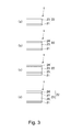
- Parts (a) to (d) of Figure 3 are illustrations of structures of photosensitive layers of other photosensitive drums.
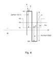
- Figure 4 is an illustration of an oscillating voltage applied to a developing sleeve.
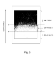
- Figure 5 is an illustration of a trailing end improper development.
- Figure 6 is an illustration of a toner on the developing sleeve opposing a non-image region of the photosensitive drum.
- Figure 7 is an illustration of the toner having reached a trailing end of an image region.
- Figure 8 is an illustration of a toner locus in a developing process in the image region.
- Figure 9 is an illustration of a range in which the trailing end improper development is not generated.
- Figure 10 is an illustration of a practical range in which the trailing end improper development is not generated.
- Figure 11 is an illustration of a surface potential of the photosensitive drum before and after development.
- Figure 12 is an illustration of a developing property.
- Figure 13 is an illustration of a developing bias.
- Figure 14 is an illustration of loci of toner particles obtained by model calculation.
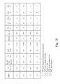
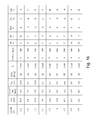
- Figures 15 and 16 are illustrations of experimental results under contacts in Embodiment 1 and Comparison Example 1, respectively.
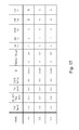
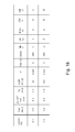
- Figures 17 and 18 are illustrations of experimental results under contacts in Embodiment 2 and Comparison Example 2, respectively.
- Figures 19 and 20 are illustrations of experimental results under contacts in Embodiment 3 and Comparison Example 3, respectively.
- Embodiments of the present invention will be described specifically with reference to the drawings.
- the present invention can also be carried out in other embodiments in which a part or all of constitutions of the following embodiments are replaced with alternative constitutions so long as a member for regulating a layer thickness of a developer also functions as a member for rectify a flow of the developer in its upstream side and thus is unified into a single part.
- the present invention can also be carried out by an image forming apparatus including a developing device using not only a two-component developer but also a one-component developer.
- an image forming apparatus including a developing device using not only a two-component developer but also a one-component developer.
- the present invention can be carried out in various fields of apparatuses or machines such as printers, various printing machines, copying machines, facsimile machines, and multi-function machines.
- Figure 1 is an illustration of a structure of an image forming apparatus 100.
- the image forming apparatus 100 is a monochromatic printer in which a toner image is transferred and fixed on a recording material conveyed one by one.
- the image forming apparatus 100 includes a photosensitive drum 1, around which a corona charter 2, an exposure device 3, a developing device 4, a transfer charger 5 and a drum cleaning device 7 are provided.
- the photosensitive drum 1 has a photosensitive layer at its outer peripheral surface, and is rotated in an arrow A direction at a predetermined process speed.
- the corona charger 2 emits negatively charged particles with corona discharge, thus electrically charging the photosensitive drum 1 to a uniform negative dark portion potential VD.
- the exposure device 3 scans the photosensitive drum surface, through a rotating mirror, with a laser beam obtained by ON-OFF modulation of a scanning line image signal developed from a monochromatic image and thus the surface potential of the charged photosensitive drum 1 is lowered to a light portion potential VL, so that an electrostatic image for an image is written (formed) on the photosensitive drum 1.
- the developing device 4 transfers a toner onto the photosensitive drum 1 to develop the electrostatic image into a toner image.
- a separation roller 62 separates sheets of the recording material P, one by one, pulled out from a recording material cassette 61, and sends the recording material P to a registration roller pair 64.
- the registration roller pair 64 sends the recording material P to a transfer portion 51 while timing the recording material P to the toner image on the photosensitive drum 1.
- the recording material P on which the toner image is transferred is subjected to application of heat and pressure by a fixing device 6, so that the toner image is fixed on the surface of the recording material P.
- the drum cleaning device 7 rubs the photosensitive drum 1 with a cleaning blade to remove a transfer residual toner deposited on the photosensitive drum 1 without being transferred onto the recording material P.
- a pre-exposure device 8 irradiates the surface of the photosensitive drum 1 with light to electrically initialize the photosensitive drum surface, thus enabling repetition of the above-described image forming operation.
- Figure 2 is an illustration of a structure of the photosensitive layer of the photosensitive drum 1.
- Parts (a) to (d) of Figure 3 are illustrations of photosensitive layer structures of other photosensitive drums 1.
- an ordinary OPC type photosensitive member which is a photosensitive member including at least an organic photoconductor layer is used.
- the OPC type photosensitive member is prepared by forming, on an electroconductive support, a photosensitive layer (photosensitive film) including a photoconductive layer formed of an organic photoconductor as a main component.
- a photosensitive layer photosensitive film
- layers consisting of a charge generating layer 12, a charge transporting layer 13 and a surface protective layer which are formed of organic materials are laminated.
- an a-Si photosensitive member which is a photosensitive member including at least an amorphous silicon layer.
- the a-Si photosensitive member includes the electroconductive support and a photosensitive layer (photosensitive film), provided on the support, including a photoconductive layer principally formed of an amorphous silicon.
- the a-Si photosensitive member generally has the following layer structures.
- the layer structure of the photosensitive drum 1 is not limited to those as shown in Figures 2 and 3 but the photosensitive drum 1 may also have other layer structures.
- an output image has a value as an original output product and thus the image forming apparatus is expected to move into a printing market.
- the image forming apparatus is required to output an image with high and stable image quality (high definition).
- the image forming apparatus is required that a developing property is improved and a degree of image defect is reduced.
- the developing device 4 carries on a developing sleeve 41 a two-component developer obtained by mixing a toner T as non-magnetic toner particles with a carrier C as magnetic carrier particles in a weight ratio of about 10 %, and supplies the developer to the photosensitive drum 1, thus developing the electrostatic image into the toner image.
- the toner image is substantially formed only of the toner of the two-component developer.
- the toner and the carrier in the present invention are not limited but specifically those of various types described later may be used.
- the toner may preferably contain a wax as a parting agent and a charge control agent such as an organic metal complex.
- a desired toner charge amount Q/M is ensured by adjusting the weight ratio of the toner to the carrier and the type and amount of an external additive to be added to the toner.
- a developing container (developing device body) 44 accommodates the two-component developer.
- the developing sleeve 41 is rotatably provided at an opening of the developing container 44 and incorporates therein a magnet 42 as a magnetic field generating means.
- the developing sleeve 41 is rotated so that its surface moves in a B direction, which is the same direction as that of the photosensitive drum 1, at a developing portion G where the developing sleeve 41 opposes the photosensitive drum 1.
- the developing sleeve 41 is rotationally driven so that its surface moves at a speed Vs higher than that of the photosensitive drum 1.
- the two-component developer is carried on the surface of the developing sleeve 41 in the developing container 44 and then a layer thickness of the developer is uniformly controlled by a layer thickness regulating member 43, and thereafter the developer is conveyed to the developing portion G where the developing sleeve 41 opposes the photosensitive drum 1.
- a positively charged carrier C is constrained by the surface of the developing sleeve 41 and adsorbs a negatively charged toner T to convey the toner T to the developing portion G.
- the toner T is stirred and mixed with the carrier C to be triboelectrically charged to the desired toner charge amount Q/M.
- the two-component developer on the developing sleeve 41 is erected at the developing portion G by the magnetic field generated by the magnet 42 to form a magnetic brush, so that the surface of the photosensitive drum 1 is rubbed with an end of the magnetic brush.
- An oscillating voltage in the form of a DC voltage Vdc biased with an AC voltage Vac is applied to the peripheral speed 41, so that only the toner T is transferred from the developing sleeve 41 onto the photosensitive drum 1.
- the photosensitive drum 1 is negatively charged, and the electrostatic image is formed by an image exposure system in which the electrostatic image is formed by effecting exposure at an image portion.
- the toner is charged to the negative polarity identical to a charge polarity of the photosensitive drum 1 by triboelectric charge with the carrier.
- the electrostatic image is developed into the toner image by a reverse development system in which the electrostatic image is developed at the image portion exposed to light on the photosensitive drum 1.
- FIG 4 is an illustration of the oscillating voltage applied to the developing sleeve.
- an abscissa represents a time, and an ordinate represents a potential.
- the developing bias is the oscillating voltage in the form of the DC voltage Vdc, determined as an intermediate value between the above-described light portion potential VL and dark portion potential VD, biased with the AC voltage Vac having a peak-to-peak voltage Vpp which has peak potentials Vp1 and Vp2.
- the developing bias is applied between the photosensitive drum 1 and the developing sleeve 41.
- the dark portion potential VD is the negative potential of the photosensitive drum 1 charged by the corona charger 2.
- the light portion potential VL is the potential of the first portion where the dark portion potential VD is lowered by subjecting the photosensitive drum 1 to exposure to light by the exposure device 3.
- the light portion potential VL is the potential at which a toner deposition amount becomes largest to obtain a maximum density of the fixed image.
- a field intensity Ea of the developing electric field and a field intensity Eb of the pull-back electric field are represented by the following formulas (1) and (2), respectively.
- Ea Vp ⁇ 1 - VL / D
- Eb Vp ⁇ 2 - VL / D
- VL electrostatic image potential (V) for obtaining maximum density
- Vp1 peak potential (V) of oscillating voltage for moving toner to photosensitive drum portion with light portion potential
- Vp2 peak potential (V) of oscillating voltage for moving toner from photosensitive drum portion with light portion potential VL to developing sleeve 41
- Vdc PC component (V) of oscillating voltage
- D closest distance (m) between photosensitive drum 1 and developing sleeve 41
- the field intensity Ea of the developing electric field is referred to as a developing field intensity.
- the field intensity Eb of the pull-back electric field is referred to as a pull-back field intensity.
- Figure 5 is an illustration of the trailing end improper development.
- the two-component developer carried on the developing sleeve 41 provided to the developing device 4 is conveyed to the developing portion G where the developer opposes the electrostatic image on the photosensitive drum 1. Then, in a state in which the magnetic chain of the two-component developer on the developing sleeve is caused to contact or come near to the photosensitive drum 1, only the toner is moved onto the photosensitive drum 1 by the developing bias applied between the developing sleeve 41 and the photosensitive drum 1, so that the toner image depending on the electrostatic image is formed.
- the two-component development type for the purposes of improving the developing property and of reducing the degree of image defect, various contrivances are made.
- One of the contrivances is provision of a peripheral speed difference between the developing sleeve and the photosensitive drum.
- a peripheral speed difference between the developing sleeve and the photosensitive drum.
- the image defect is generated.
- One of the types of the image defect is image defect caused by a lowering in image density at a trailing end (portion) of the image. This is conspicuous particularly in the case of an image with intermediary gradation level (halftone image) of a digital type. It would be considered that the image defect is generated by the following three reasons.
- the present inventors prepares, not an actual copying machine, an experimental machine for high-speed shooting which simulates the actual copying machine, and shoots the toner behavior by using the experimental machine to observe the toner behavior in slow motion, thus specifying the mechanism of the trailing end improper development.
- the experimental machine is specifically constituted by a high-speed camera, a developing device for the experimental machine, and a charging drum of aluminum.
- a high-speed camera a high-speed camera ("APX-RS", mfd. by Photron Ltd.) was used.
- the developing device for the experimental machine was prepared in the same cross-sectional constitution and dimension as those of the image forming apparatus 100, and a diameter was 84 mm for the charging drum (corresponding to the photosensitive drum 1) and was 24.5 mm for the developing sleeve. In view of shooting, a length of each of the charging drum and the developing sleeve with respect to a rotational axis direction was 16 mm.
- As the charging drum a cylindrical member of aluminum the surface of which is coated with an about 30 ⁇ m-thick film of indium-tin oxide was used.
- a rubber roller For charging the charging drum (corresponding to formation of the electrostatic image), a rubber roller was used.
- a material of a rubber used for the rubber roller may only be required to maintain electroconductivity and is not limited.
- First and Second (two) rubber rollers were used and provided upstream of the developing device for the experimental machine with respect to the rotational direction of the charging drum.
- the first number roller was disposed upstream of the second rubber and to which the function of charging the charging drum uniformly to the dark portion potential VD was imparted.
- an oscillating voltage was applied so that a 10 mm-portion of the light portion potential VL was intermittently formed, as the electrostatic image, at an interval of 10 mm with respect to the rotational direction in a region where the charging drum was uniformly charged to the dark-portion potential VD.
- a high-voltage source unit was connected to the first and second rubber rollers, and a voltage applied from the high-voltage source unit is adjusted so that each of the dark portion potential VD and the light portion potential VL to which the charging roller was charged was a desired potential.
- a trailing end improper development phenomenon itself can be regarded as being the same between the actual machine of the image forming apparatus and the experimental machine for high-speed shooting. Further, by analyzing the toner behavior by using motion picture images shot by the experimental machine for high-speed shooting, a cause of the image defect generated in the actual machine of the image forming apparatus could be formed.
- the trailing end improper development phenomenon is a phenomenon generated because movement of the toner attracted toward the developing sleeve is not in time when the developing sleeve has the higher peripheral speed than that of the photosensitive drum.
- a length of the trailing end improper development generated on the charging drum tended to be longer than that observed by print output by the actual machine.
- This may be because the toner image formed on the photosensitive drum by development is subjected to a fixing process in which the image is fixed on the recording material, after being subjected to a transfer process in which the toner image is transferred onto the recording material. That is, in the transfer process, the location of the toner image on the photosensitive drum cannot be accurately reproduced on the paper (recording material), so that an amount of the toner scattered onto the non-image portion is not so small.
- Figure 6 is an illustration of a toner on the developing sleeve opposing a non-image region of the photosensitive drum.
- Figure 7 is an illustration of the toner having reached a trailing end of an image region.
- Figure 8 is an illustration of a toner locus in a developing process in the image region.
- Figures 6, 7 and 8 are schematic views drawn by paying attention to a sing particle of the toner T during the developing process. For brief explanation, only the single particle of the toner is drawn, so that other toner particles and carrier particles at a periphery of the single toner particle are omitted from illustration.
- an electrostatic image S is formed on the photosensitive drum 1 and the toner T opposes the non-image region in front of the electrostatic image S.
- the potential of the electrostatic image S is -300 V
- the potential in the non-image region is -500 V
- the DC voltage of the developing bias applied to the developing sleeve 41 is -350 V
- the toner is charged to the negative polarity.
- the toner T is positioned upstream of the electrostatic image in the developing region G and opposes the non-image region.
- the negatively charged toner T is attracted to the developing sleeve 41.
- the toner T opposes the non-image region and based on a potential relationship, is attracted to the developing sleeve 41.
- the magnetic chain formed by the carrier and carried on the developing sleeve 41 is rotated at the speed equal to that of the developing sleeve 41 and therefore also the toner T carried on the magnetic chain (or the toner T floating between closely formed magnetic chains) is moved at the speed equal to that of the developing sleeve 41.
- the speed of the toner T in an x direction is Vs.
- the developing sleeve 41 is rotated at the speed higher than that of the photosensitive drum 1 and therefore the toner T surrounded by the magnetic chain of the developer is moved in the x direction at the speed equal to that of the developing sleeve 41.
- the peripheral speed Vs of the developing sleeve 41 is set at a value larger than that of the peripheral speed of the photosensitive drum 1. For that reason, the toner opposing the non-image region of the photosensitive drum 1 catches up with the trailing end of the electrostatic image S in a state in which the toner is still attracted to the developing sleeve 41, and then starts to move toward the photosensitive drum 1 in response to the potential difference between the photosensitive drum 1 and the developing sleeve 41.
- the trailing end improper development phenomenon stands out in relief.
- the toner opposing the non-image region is attracted to the developing sleeve 41 based on the potential relationship. Further, when there is no peripheral speed difference between the developing sleeve 41 and the photosensitive drum 1, the trailing end improper development is not generated. However, unless the amount of the toner sent to the developing portion G is increased by providing the peripheral speed difference at a certain level or more, at a high process speed, the toner supply is insufficient and thus the developing property is remarkably lowered. For this reason, the developing sleeve 41 is rotated at the peripheral speed higher than that of the photosensitive drum 1, so that the toner T is moved to a position where the toner T opposes the image region.
- the toner T starts development from the time when it catches up with the electrostatic image S by the peripheral speed difference between the developing sleeve 41 and the photosensitive drum 1.
- the toner T cannot reach the trailing end of the image region which first opposes the toner T, so that the electrostatic image is developed with the toner at a place spaced from the image region trailing end by a certain distance X.
- the toner image with the trailing end improper development is visualized macroscopically. With respect to a halftone image, visual sensitivity to a difference in toner amount per unit area becomes high and therefore a density difference in trailing end improper development becomes conspicuous especially.
- the toner originally placed in the state in which it is attracted to the developing sleeve 41 reaches the photosensitive drum 1 along its locus, thus developing the electrostatic image into the toner image.
- the locus can be mathematically analyzed as described later.
- the present inventors analyzed the shot image to study shortening of a time Tsd required until the toner reaches the photosensitive drum 1. In the following, a generating mechanism of the trailing end improper development and a measuring method of the time will be described.
- the present inventors analyzed the shot motion picture images of the experimental machine for high-speed shooting by a manual operation, so that the time Tsd required until an individual toner particle reached from the developing sleeve to the charging drum was measured.
- many still picture images constituting the motion picture images was edited by using an editing software for a photographic image ("Adobe Photoshop CS2" (registered trademark), available from Adobe Systems Inc.).
- a contour of the toner particle was emphasized by subjecting the still picture images to unsharp mask so as to be converted into gray-scale images.
- the individual toner particle was tracked by eye observation by using an image analyzing software ("Image-Pro Plus” (registered trademark), available from Adobe Systems Inc.) to specify a movement position of each still picture image for motion picture image.
- Image-Pro Plus registered trademark
- the times required until 100 toner particles reached the charging drum was individually measured, and were averaged to obtain the time Tsd required until each toner particle reached the charging drum.
- the motion picture image shot by the experimental machine for high-speed shooting is an aggregate of the still picture images and is discontinuous in terms of time, and therefore the toner particle may only be required to be accidentally shot as an image at an instant when it reaches the charging drum but is ordinarily shot as two continuous images consisting of an image thereof before reaching and an image thereof bounced after reaching.
- the time required until the toner particle reaches the charging drum cannot be accurately specified but when a shooting frame rate of the high-speed camera is increased to a certain level, the time may be substituted with an intermediate value for the images before and after the toner particle reaches the charging drum.
- the high-speed camera frame rate is 500,000 frames/sec or more, it would be considered that an error is less even when the time is substituted with the intermediate value.
- the reason therefor is that in the case where the toner particle is shot at the frame rate of 500,000 frames/sec or more, a time interval between the two still picture images is 1/500,000 sec or less, i.e., 2 ⁇ sec or less although it depends on a shutter speed. Therefore, the error, of the time required until the toner particle reaches the charging drum, generated by using the intermediate value of the images before and after the toner particle is suppressed to 2 ⁇ sec or less, so that sufficient accuracy can be ensured with respect to the time Tsd at a level of 100 - 300 ⁇ sec.
- Figure 9 is an illustration of a range in which the trailing end improper development is not generated.
- Figure 10 is an illustration of a practical range in which the trailing end improper development is not generated.
- the magnetic chain formed of the carrier is closely present actually.
- the rotational direction of the developing sleeve 41 is the x direction.
- the toner removed from the carrier becomes in motion between the closely present magnetic chains and therefore the toner is rotated in the same direction as that of the developing sleeve 41 at the speed equal to that of the magnetic chain.
- the magnetic chain is carried on the developing sleeve 41, and the toner is rotated while being constrained by the magnetic chain and therefore, at the developing portion G, the speed of the toner with respect to the x direction is equal to that of the developing sleeve 41.
- a position x(t) of the toner with respect to the x direction at an arbitrary time t is represented by the following formula (6).
- x t x 0 + V s ⁇ t
- the developing sleeve 41 has the peripheral speed higher than that of the photosensitive drum 1 and therefore the toner moved in the x direction at the speed equal to that of the developing sleeve 41 necessarily passes the electrostatic image, so that the position of the opposing electrostatic image is changed in real time.
- the distance X from the trailing end of the image on the photosensitive drum at the toner-opposing position is represented by the following formula (7).
- the toner T starts movement from the developing sleeve 41 and reaches the surface of the photosensitive drum 1 with reciprocation movement in response to a pulse polarity of the AC voltage of the oscillating voltage.
- the toner T passes the photosensitive drum 1 by the distance X represented by the formula (7) and therefore the toner T does not develop the electrostatic image on the photosensitive drum at a point B but develops the electrostatic image at a point B' spaced from the point B by the distance X with respect to the photosensitive drum rotational direction.
- the distance X was determined as a visually allowable range. This is because at present, as the carrier used for electrophotography, particles of about several tens of ⁇ m in particle size are used and when even one particle of the carrier is deposited on the image as an output product, the carrier is visualized as the image defect and therefore a minimum of distance X is required to be in a range smaller than the carrier particle size. Further, when the distance X is 30 ⁇ m or less, the resultant image is actually allowable as an image. This is also confirmed by study of the present inventors. Thus, from the formula (7), the following formula (8) is obtained. Vsd ⁇ 30 ⁇ x ⁇ 10 - 6 / Tsd
- a region represented by the formula (8) is shown in Figure 9 as a hatched line portion.
- the peripheral speed difference Vsd between the developing sleeve 41 and the photosensitive drum 1 closely relates to also the developing property, the carrier deposition, and an image property such as disturbance of the image. For that reason, the peripheral speed difference Vsd is not required to only satisfy the formula (8) but is required to find out a condition for satisfying the formula (8) while satisfying the developing property and the image property.
- a performed range of an ideal peripheral speed difference Vsd study was made in Embodiments 1 to 3, so that the range was specified.
- the specified range (region) in Embodiments 1 to 3 is shown in Figure 10 as a hatched line portion.
- An object of the following embodiments is to provide an image forming apparatus capable of obtaining a high developing property while reducing a degree of the trailing end improper development and also ensuring an opportunity to develop the electrostatic image with the toner.
- Figure 15 is an illustration of an experimental result under an operating condition in Embodiment 1.
- Figure 16 is an illustration of an experimental result in Comparison Example 1.
- the exposure device 3 as an example of an electrostatic image forming means forms the electrostatic image on the photosensitive drum 1 as an example of the image bearing member.
- the developing device 4 as an example of the developer carrying member is provided and spaced from the photosensitive drum 1 with a predetermined gap from the photosensitive drum 1, and magnetically attracts the developer and rotates in the same direction as that of the opposing surface of the photosensitive drum 1 at the peripheral speed higher than that of the photosensitive drum 1.
- the developing sleeve 41 rubs the photosensitive drum 1 with the magnetic chain of the developer, containing the toner and the carrier, with the predetermined gap to develop the electrostatic image.
- a voltage source D4 as an example of the voltage source applies the oscillating voltage, in the form of the predetermined DC voltage biased with the predetermined AC voltage, to the developing sleeve 41.
- the peripheral speed of the photosensitive drum 1 is Vp
- the peripheral speed of the developing sleeve 41 is Vs
- the actually measured time of movement of the developer from the developing sleeve 41 to the photosensitive drum 1 in the predetermined gap is Tsd.
- the peripheral speed Vp of the photosensitive drum 1 is 0.1 m/sec or more and 0.5 m/sec or less, and the relationship: 0.2 (m/sec) ⁇ (Vs-Vp) ⁇ 0.5 (m/sec) is satisfied.
- An evaluation method of the image forming apparatus is as follows. At a boundary position of the electrostatic image on the photosensitive drum 1 with respect to the rotational direction, the time of the movement of the toner from the developing sleeve 41 to the photosensitive drum 1 is actually measured. Then, whether or not the measured time is shorter than a predetermined time associated with the trailing end improper development is discriminated. As a result, whether or not a combination of various conditions such as the opposing distance, the relative speed, the field intensity, and the toner charge amount Q/M is problematic in terms of the trailing end improper development can be accurately discriminated. Properness of these many physical parameters can be evaluated by using only a single parameter actually measured.
- Tsd is the parameter of the trailing end improper development.
- the experimental machine for high-speed shooting is a simulation apparatus of the toner behavior in an opposing gap in which an operation state of the photosensitive drum 1 and developing sleeve 41 is reproduced in cross-section perpendicular to the axis by using the charging drum and the developing sleeve.
- the opposing distance between the charging drum and the developing sleeve is shot as the motion picture image from the rotational axis direction to track the individual toner particle on the still picture image constituting the motion picture image, thus obtaining the time Tsd of the movement of the toner particle from the developing sleeve 41 to the photosensitive drum 1.
- the toner particle tracked in the still picture image is the toner particle moved in the opposing gap from a position opposing a potential region corresponding to the dark portion potential to a potential region corresponding to the light portion potential with rotation of the charging drum.
- Embodiment 1 in the image forming apparatus 100, the trailing end improper development was evaluated by variously changing the peripheral speed Vs of the developing sleeve 41, the peripheral speed Vp of the photosensitive drum 1, values of a frequency f and peak-to-peak voltage Vpp of the applied developing bias, and the toner charge amount per unit weight Q/M.
- the developing property and image property (carrier deposition, graininess, fog) of the output image were evaluated. In the case where any one of these properties is out of an allowable range, the result is regarded as being the case where an image evaluation criterion in Embodiment 1 is not satisfied, thus falling in the evaluation result of Comparison Example 1.
- the developing sleeve peripheral speed Vs, the charging drum peripheral speed Vp and the peripheral speed difference between the developing sleeve and the charging drum were changed, and the time Tsd required until the toner reaches the charging drum was actually measured by using the above-described procedure.
- the image forming apparatus 100 ( Figure 1 ) was operated under the same condition to measure remaining items, so that a relationship between each value and an associated one of the measuring items described above was measured and then was evaluated in accordance with each evaluation criterion described later.
- Embodiments 1-1 to 1-4 under operating conditions of Embodiments 1-1 to 1-4, all of the evaluation criteria were satisfied.
- the peripheral speed difference Vsd is 0.2 - 0.5 (m/sec) and the photosensitive drum peripheral speed Vp is 0.1 - 0.5 (m/sec)
- the trailing end improper development distance, the developing property and the image property satisfy the evaluation criteria described later and thus are compatibly realized.
- Vp is 0.1 (m/sec) or more and 0.5 (m/sec) or less.
- the upper limit of the peripheral speed Vp is provided because when the peripheral speed Vs of the developing sleeve 41 is 1.0 (m/sec) or more, a centrifugal force exerted on the carrier exceeds a magnetic retaining force of the developing sleeve 41 and thus the carrier is deposited on the photosensitive drum 1.
- the lower limit of the peripheral speed Vp is provided because when the speed at a certain level or more is not originally provided to the photosensitive drum 1, productivity cannot be obtained. Further, when the peripheral speed Vp of the photosensitive drum 1 is excessively small, there is also a problem that a degree of fog is worsened.
- a region between lines A and B is the region where the density is 0.3 or less, and in the region, a distance of the recording material with respect to the recording material conveyance direction is the trailing end improper development distance X.
- the density referred to herein is a transmission density DT measured by using a transmission densitometer ("TD-904", mfd. by Gretag Macbeth). The reason why the transmission density DT is used is that a relationship between the toner amount per unit volume and the image density is described in a state the influence of glossiness resulting from a surface state of the toner layer on the recording material is eliminated.
- the recording material used was "OK Top Coat” (basis weight: 73.3 g/m 2 ) manufactured by Oji Holdings Corp. In the following description, all the recording materials are this coated paper.
- the trailing end improper development distance when the peripheral speed difference Vsd between the developer carrying member and the image bearing member and the time Tsd required until the toner reaches the image bearing member are decreased, the trailing end improper development distance can be shortened.
- the time Tsd required until the toner reaches the charging drum may only be required to be shortened. According to study by the present inventors, when the trailing end improper development is 20 ⁇ m or less, the distance may be discriminated that it falls under a visually allowable range.
- the trailing end improper development distance X is 30 ⁇ m or less
- the distance was discriminated that it fallen under the visually allowable range.
- Tsd time required until the toner reaches the image bearing member, in the proper range
- the lowering in image density of the half-tone image at the trailing end portion can be caused to fall within the visually allowable range without decreasing the opportunity to develop the electrostatic image with the toner.
- Figure 11 is an illustration of a surface potential of the photosensitive drum before and after the development.
- Figure 12 is an illustration of the developing property.
- Vcont represents a potential difference between a DC component of the developing bias and the high portion potential VL at a development portion of the photosensitive drum.
- ⁇ V represents a potential difference between the toner layer surface potential at the electrostatic image potential portion after the development and the electrostatic image potential before the development.
- ⁇ V of the photosensitive drum corresponding to the image region is the potential difference between the toner layer surface potential, after the development, of the light portion potential VL corresponding to the image region and the light portion potential before the development.
- the light portion potential VL and the toner layer surface potential were measured by a surface electrometer at the developing position or in the neighborhood of the developing position.
- a charging efficiency is a percentage of a charging potential ⁇ V to the developing contrast Vcont as shown in a formula (9) below.
- the developing property was evaluated by using the charging efficiency defined by the following formula (9).
- Charging efficiency charging potential ⁇ V / developing contrast Vcont x 100 %
- FIG. 11 Potential profiles of the electrostatic image potential before the development and the electrostatic image potential after the development which are obtained by the above two methods are shown in Figure 11 .
- Figure 11 by subtracting the surface potential value of the electrostatic image potential before the development from that of the electrostatic image potential after the development, ⁇ V generated by actually developing the electrostatic image with the toner can be obtained.
- the percentage of ⁇ V to Vcont is the charging efficiency.
- the developing contrast Vcont is determined at the developing position. That is, a dedicated surface electrometer is provided at the position of the developing device 4 to measure the electrostatic image potential of the developing device, and then Vdc with respect to the measured electrostatic image potential is determined to ensure Vcont at the developing position.
- the obtained fog density was evaluated in accordance with the following evaluation criterion.
- the carrier deposition was evaluated as follows. When a toner image with a maximum density was formed on the photosensitive drum (solid image development) and then a main power switch was turned off, the toner image remaining on the photosensitive drum was collected by using a tape. The tape was observed through an optical microscope (mfd. by Olympus Corp.), and the number of carrier particles present in 5 cm 2 of the toner image was counted to calculate the number of the carrier particles per unit area.
- the carrier deposition was evaluated depending on a carrier deposition number Z (particles/cm 2 ) in accordance with the following evaluation criterion.
- the evaluation C was a level such that the carrier transferred on the recording material and a trance of the carrier which had not been transferred onto the recording material were sufficiently recognized as a white portion remaining on the recording material as an image defect.
- the image non-uniformity was evaluated as follows. A half-tone image (lightness L*: nearly equal 70) for which graininess is liable to be conspicuous was subjected to visual evaluation in accordance with the following evaluation criterion.
- Figure 17 is an illustration of an experimental result under an operating condition in Embodiment 2.
- Figure 18 is an illustration of an experimental result under an operating condition in Comparison Example 2.
- Embodiment 2 similarly as in Embodiment 1, Tsd was measured by using the experimental machine for high-speed shooting, and the image was evaluated by using the image forming apparatus 100.
- the respective evaluation items were measured and evaluated similarly as in Embodiment 1 by changing the toner charge amount Q/M.
- a composition and mixing amount of an external additive to be added to the toner and the carrier In order to increase and decrease the toner charge amount Q/M while keeping conditions of the toner and the carrier, a composition and mixing amount of an external additive to be added to the toner and the carrier.
- Embodiments 2-1, 2-2 and 2-3 conditions satisfying requirements of the embodiments of the present invention are shown as Embodiments 2-1, 2-2 and 2-3.
- Tsd is changed. This is because followability to the applied electric field varies and influences the trailing end improper development distance. Further, when the toner charge amount is increased, an opposite electric charge generated on the carrier is also increased, and an electrostatic attraction force between the toner and the carrier is also increased. For that reason, ease of separation of the toner from the carrier is also changed and therefore as a result, the toner charge amount has the influence on the developing property.
- the toner charge amount per unit weight Q/M ( ⁇ C/g)
- a relationship: 60 ⁇ Q/M ⁇ 150 is satisfied. That is, the toner charge amount Q/M may preferably fall within a range of 60 - 150 ⁇ C/g.
- Figure 19 is an illustration of an experimental result under an operating condition in Embodiment 3.
- Figure 20 is an illustration of an experimental result under an operating condition in Comparison Example 3.
- Embodiment 3 similarly as in Embodiment 1, Tsd was measured by using the experimental machine for high-speed shooting, and the image was evaluated by using the image forming apparatus 100.
- the respective evaluation items were measured and evaluated similarly as in Embodiment 1 by changing the field intensity applied between the developing sleeve and the photosensitive drum.
- Embodiments 3-1, 3-2 and 3-3 conditions satisfying requirements of the embodiments of the present invention are shown as Embodiments 3-1, 3-2 and 3-3.
- the field intensity is changed, a movement speed of toner particles having the same toner charge amount Q/M is changed and thus also Tsd is changed, and therefore the trailing end improper development distance is changed.
- the field intensity is high, a force for separating the toner from the carrier is also strengthened. For this reason, also the developing property is improved but when metal powder or the like is included, there is such a harmful effect that electric discharge is induced and thus the photosensitive layer is deteriorated. For that reason, it is undesirable that the field intensity is increased endlessly.
- a maximum field intensity by a predetermined AC voltage in a direction toward the photosensitive drum 1 is E (V/m)
- the maximum field intensity E satisfied a relationship: 2.0x10 6 ⁇ E ⁇ 1.0x10 7 .
- An AC component of the developing bias may preferably be 0.2x10 -7 to 1.0x10 -7 (V/m). This range of the field intensity E is irrespective of the developing electric field and the pull-back electric field.
- Embodiments 1, 2 and 3 by lowering the frequency of the developing bias, it is possible to increase the movement distance of the toner in one period of the developing bias, so that the trailing end improper development distance can be shortened.
- a low-frequency developing bias worsen the image defect which is called "fog" such that the toner is deposited on the non-image portion, so that the frequency cannot be lowered endlessly.
- a frequency (f) of a proper developing bias varies, according to a result of study by the present inventors, depending on selected toner and carrier but may preferably fall within the following range of a formula (11). 3 ⁇ f ⁇ 9 kHz
- a distance in which the toner is required to be moved is shortened by decreasing the closest distance between the developing sleeve and the photosensitive drum and therefore the time Tsd required until the toner reaches the photosensitive drum is shortened and thus also the trailing end improper development distance is shortened.
- the field intensity between the developing sleeve and the photosensitive drum is strengthened. Therefore, similarly for the reason why the field intensity range is defined, the electric discharge at the developing portion becomes conspicuous unpreferably.
- the proper closest distance D between the developing sleeve and the photosensitive drum varies, according to a result of study by the present inventors, depending on a depositing force between selected toner and carrier but may preferably fall within the following range of a formula (12). 250 ⁇ D ⁇ 450 ⁇ m
- Figure 13 is an illustration of the developing bias.
- Figure 14 is an illustration of a locus of toner particle obtained by model calculation.
- Embodiments 1, 2 and 3 by using the actually measured value of the time Tsd, the range in which the trailing end improper development was not substantially generated and the above-described other evaluation items were also satisfied was defined.
- the trailing end improper development distance D cannot be accurately controlled when it is uncertain that the time Tsd required until the toner reaches the photosensitive drum 1 is dominated by what device parameter. Therefore, in the following, in order to support the data in Figures 15 to 20 and to replenish a missing data range in Figures 15 to 20 , a simple model was set and then Tsd was calculated. The toner behavior was described by using the simple model and from its result, a parameter which dominated the time Tsd was extracted.
- the locus of the toner T, which is separated from the carrier and then is moved, with respect to y direction of the photosensitive drum 1 can be described by using an equation of motion of a formula (13) below.
- the first term of the right side represents a force exerted from the electric field
- the second term of the right side represents air resistance.
- the developing bias includes an AC component of rectangular wave and therefore depending on switching of peak, the field intensity E in the formulas (14) and (15) are changed. That is, the formulas (14) and (15) are applicable to only a half period of the developing bias.
- the polarity of the AC voltage pulse is inverted every one increase in the number of pulses (n).
- the toner particle is driven by the developing contrast while being influenced by the polarity inversion of the AC voltage pulse, thus being moved from the developing sleeve to the photosensitive drum.
- a distance of the toner from the developing sleeve and a toner speed after the pulse of the AC voltage Vac is applied one time are y 1 and v 1 , respectively.
- a toner speed v 2 (t) and a toner position y 2 (t) are represented by the following formulas (16) and (17).
- a toner speed v 3 (t) and a toner position y 3 (t) during third-time pulse application are represented by the following formulas (18) and (19).
- a toner speed v n (t) and a toner position y n (t) during n-th pulse application can be generalized and represented by the following formulas (20) and (21).
- the upper formula in the formula (22) represents a field intensity for moving the toner from the developing sleeve to the photosensitive drum.
- the lower formula in the formula (22) represents a field intensity for pulling-back the toner from the photosensitive drum to the developing sleeve.
- the toner opposes the non-image region on the photosensitive drum 1 and therefore is attracted toward the developing sleeve 41 by the electrostatic force.
- the toner catches up with the electrostatic image S indicated by a broken line and at an instance when the toner opposes the electrostatic image S, the toner is moved toward the opposing point B on the photosensitive drum 1 in accordance with the formula (15).
- the time Tsd represents a time required until the toner position with respect to y direction becomes equal to the closest position between the developing sleeve and the photosensitive drum. Assuming that during application of the n-th pulse of the developing bias AC voltage, the toner position with respect to y direction becomes equal to the closest position between the developing sleeve and the photosensitive drum after a lapse of the time Tsd from the n-th pulse application, the following formula (23) is satisfied.
- the time Tsd is the sum of the time tsd from the n-th pulse application until the toner reaches the photosensitive drum and a time from start of movement of the toner from the developing sleeve surface, i.e., from the first pulse application until the toner reaches the photosensitive drum.
- the time tsd in the formula (23) is the time with respect to the n-th pulse and therefore in order to calculate the time Tsd, there is a need to add the time tsd with respect to the n-th pulse to the sum of the times with respect to the pulses from the first pulse to the (n-1)-th pulse.
- the time with respect to one pulse is 1/2 of the time of one period, i.e., 1/2f and therefore the time Tsd can be represented by the following formula (24).
- T sd t sd + n - 1 2 ⁇ f
- the distance X given by the formula (7) in which the toner catches up with the electrostatic image is equal to the trailing end improper development distance X in the model in this embodiment. Therefore, when the peripheral speed difference Vsd between the developing sleeve and the photosensitive drum and the time Tsd required until the toner reaches the photosensitive drum are decreased, the trailing end improper development distance X can be shortened as described above.
- the charge amount and particle size of the toner were measured by using a copying machine ("CLC5000", mfd. by Canon K.K.) and a measuring device ("E-SPART Analyzer", mfd. by Hosokawa Micron Group).
- the toner is used for developing the electrostatic image on the photosensitive drum and thereafter is transferred onto the recording material P, which is then conveyed to the fixing device 6.
- the charge amount Q/M and particle size of the toner actually used for developing the electrostatic image on the photosensitive drum were measured and therefore before the toner was transferred onto the recording material P, the electric power of the image forming apparatus 100 was turned off and then the toner was collected every photosensitive drum.
- the photosensitive drum on which the electrostatic image is developed with the toner is set on a measuring table of the measuring device ("E-START Analyzer"), and nitrogen gas is blown onto the toner on the photosensitive drum to remove the toner from the photosensitive drum, and then the toner is passed between flat plate electrodes to which the electric field is applied.
- E-START Analyzer a measuring table of the measuring device
- a sound wave is applied to the toner, so that the toner vibrates at a frequency of the sound wave.
- the toner particle is irradiated with two laser beams so as to cross each other, and by laser Doppler method, a beat frequency and a vibration phase delay of the toner are measured.
- the movement speed vi of each toner is calculated.
- the particle size di of each toner is calculated.
- the charge amount qi of each toner is obtained.
- the weight mi of each toner is converted from the particle size di and a density.
- the particle size di, the charge amount qi and the weight mi were obtained.
- a volume average of an average particle size D50 of the measured 3000 toner particles was determined as a particle size d.
- number averages of the charge amount qi and the weight mi of the measured 3000 toner particles were determined as a toner charge amount q and a toner weight m, respectively.
- the toner charge amount per unit weight Q/M refers to a number average of values each obtained by dividing the charge amount q by the weight m. Further, the particle size d, the charge amount q and the weight m which are measured by the above-described measuring methods are the same as those in the formulas (13) to (21) and (23).
- the present invention is described above based on specific embodiment but it should be understood that the present invention is not limited to the above-described embodiments and specific examples.
- the photosensitive drum was described such that it is negatively charged and the electrostatic image is formed on the photosensitive drum by the image exposure system.
- the present invention is not limited thereto but the charge polarity of the photosensitive drum may also be positive.
- the electrostatic image may also be formed on the photosensitive drum by a background exposure system in which exposure is effected at the non-image portion where the toner should not be deposited.
- a normal development system in which the toner charged to a polarity identical to the charge polarity of the photosensitive drum is used, i.e., the electrostatic image is developed at the image portion where the photosensitive drum is not exposed to light may also be used.
- JP-A 2003-323051 the method for alleviating the density lowering by controlling the magnetic chain by the arrangement of the magnetic poles is proposed. That is, an auxiliary magnetic pole is provided adjacent the main magnetic pole and an angle of the auxiliary magnetic pole is set with a proper range, so that a region where the magnetic chain contacts the image bearing member is narrowed. As a result, the toner once used for developing the electrostatic image is caused not to be readily collected by the electric charge of the carrier opposite to that of the toner.
- An image forming apparatus includes: an image bearing member; an electrostatic image forming device; and a developer carrying member.
- the developer carrying member is provided so as to be rotated in a direction opposite to a rotational direction of the image bearing member at a peripheral speed higher than that of the image bearing member.
- the peripheral speed of the image bearing member is Vp (m/sec)
- the peripheral speed of the developer carrying member is Vs (m/sec)
- a time, of movement of the developer from the surface of the developer carrying member to the image bearing member, actually measured in a gap between the image bearing member and the developer carrying member is Tsd (sec)
- the peripheral speeds Vp and Vs and the time Tsd satisfy the following relationship: (Vs-Vp) x Tsd ⁇ 3x10 5 (m).
Landscapes
- Physics & Mathematics (AREA)
- General Physics & Mathematics (AREA)
- Engineering & Computer Science (AREA)
- Microelectronics & Electronic Packaging (AREA)
- Dry Development In Electrophotography (AREA)
- Developing For Electrophotography (AREA)
Applications Claiming Priority (1)
| Application Number | Priority Date | Filing Date | Title |
|---|---|---|---|
| JP2012032551A JP2013167850A (ja) | 2012-02-17 | 2012-02-17 | 画像形成装置、画像形成装置の評価方法、およびパラメータ測定方法 |
Publications (1)
| Publication Number | Publication Date |
|---|---|
| EP2642345A2 true EP2642345A2 (de) | 2013-09-25 |
Family
ID=47750452
Family Applications (1)
| Application Number | Title | Priority Date | Filing Date |
|---|---|---|---|
| EP13155366.1A Withdrawn EP2642345A2 (de) | 2012-02-17 | 2013-02-15 | Bilderzeugungsvorrichtung |
Country Status (3)
| Country | Link |
|---|---|
| US (1) | US20130216263A1 (de) |
| EP (1) | EP2642345A2 (de) |
| JP (1) | JP2013167850A (de) |
Families Citing this family (4)
| Publication number | Priority date | Publication date | Assignee | Title |
|---|---|---|---|---|
| JP2013174778A (ja) * | 2012-02-27 | 2013-09-05 | Canon Inc | 画像形成装置 |
| JP6207284B2 (ja) | 2013-07-31 | 2017-10-04 | キヤノン株式会社 | 画像形成装置 |
| JP6150661B2 (ja) | 2013-08-12 | 2017-06-21 | キヤノン株式会社 | 現像剤補給装置 |
| JP6265695B2 (ja) | 2013-11-13 | 2018-01-24 | キヤノン株式会社 | 画像形成装置 |
Citations (1)
| Publication number | Priority date | Publication date | Assignee | Title |
|---|---|---|---|---|
| JP2003323051A (ja) | 2002-05-02 | 2003-11-14 | Ricoh Co Ltd | 画像形成装置 |
Family Cites Families (7)
| Publication number | Priority date | Publication date | Assignee | Title |
|---|---|---|---|---|
| EP0446034B1 (de) * | 1990-03-09 | 2000-09-06 | Seiko Epson Corporation | Entwicklungsgerät |
| JP2923334B2 (ja) * | 1990-06-29 | 1999-07-26 | 三田工業 株式会社 | 現像方法 |
| US6512909B2 (en) * | 2000-08-03 | 2003-01-28 | Kyocera Corporation | Image forming process and apparatus and control method thereof |
| EP1434104A3 (de) * | 2002-12-27 | 2004-11-17 | Ricoh Company, Ltd. | Magnetischer Träger, Zweikomponentenentwickler, Entwicklungsverfahren, Entwicklungsgerät und elektrophotographischer Apparat zur Bildherstellung |
| JP5207702B2 (ja) * | 2006-10-20 | 2013-06-12 | キヤノン株式会社 | 画像形成装置 |
| JP5132161B2 (ja) * | 2007-02-02 | 2013-01-30 | キヤノン株式会社 | 画像形成装置 |
| JP5207633B2 (ja) * | 2007-02-14 | 2013-06-12 | キヤノン株式会社 | 画像形成装置 |
-
2012
- 2012-02-17 JP JP2012032551A patent/JP2013167850A/ja active Pending
-
2013
- 2013-02-13 US US13/765,962 patent/US20130216263A1/en not_active Abandoned
- 2013-02-15 EP EP13155366.1A patent/EP2642345A2/de not_active Withdrawn
Patent Citations (1)
| Publication number | Priority date | Publication date | Assignee | Title |
|---|---|---|---|---|
| JP2003323051A (ja) | 2002-05-02 | 2003-11-14 | Ricoh Co Ltd | 画像形成装置 |
Also Published As
| Publication number | Publication date |
|---|---|
| US20130216263A1 (en) | 2013-08-22 |
| JP2013167850A (ja) | 2013-08-29 |
Similar Documents
| Publication | Publication Date | Title |
|---|---|---|
| EP2642345A2 (de) | Bilderzeugungsvorrichtung | |
| CN104076640A (zh) | 图像形成设备 | |
| JP2010020281A (ja) | 画像形成装置 | |
| JP2006313307A (ja) | 画像形成装置 | |
| US5428428A (en) | Developing device having a control electrode | |
| JP2010122398A (ja) | 画像形成装置における現像方法と装置 | |
| JP4920981B2 (ja) | 画像形成装置 | |
| JPH0588556A (ja) | 現像間隙設定方法,現像間隙設定装置,現像間隙自動設定装置及び電子写真装置 | |
| JPH10153910A (ja) | 現像装置および現像装置を用いた回転式の現像ユニット | |
| JP4861736B2 (ja) | 画像形成装置 | |
| JPH05281790A (ja) | 現像方法および画像形成装置 | |
| JP2768078B2 (ja) | 現像方法 | |
| JP2007322717A (ja) | 画像形成装置 | |
| JP3703314B2 (ja) | 画像形成装置 | |
| JP4348951B2 (ja) | 画像形成装置 | |
| JP3363505B2 (ja) | 現像方法 | |
| JP3961758B2 (ja) | 画像形成方法 | |
| JP2550568B2 (ja) | カラ−画像記録方法 | |
| JP2006313277A (ja) | 画像形成装置 | |
| JP2000122403A (ja) | 現像装置 | |
| JP2004341012A (ja) | 画像形成装置 | |
| JP2009139594A (ja) | 画像形成装置における現像方法及び装置 | |
| JPS61166571A (ja) | 現像装置 | |
| JP2000010386A (ja) | 現像装置および画像形成装置 | |
| JP2009014992A (ja) | 現像装置及び現像装置を備えた画像形成装置、並びに記録物の製造方法 |
Legal Events
| Date | Code | Title | Description |
|---|---|---|---|
| PUAI | Public reference made under article 153(3) epc to a published international application that has entered the european phase |
Free format text: ORIGINAL CODE: 0009012 |
|
| AK | Designated contracting states |
Kind code of ref document: A2 Designated state(s): AL AT BE BG CH CY CZ DE DK EE ES FI FR GB GR HR HU IE IS IT LI LT LU LV MC MK MT NL NO PL PT RO RS SE SI SK SM TR |
|
| AX | Request for extension of the european patent |
Extension state: BA ME |
|
| STAA | Information on the status of an ep patent application or granted ep patent |
Free format text: STATUS: THE APPLICATION HAS BEEN WITHDRAWN |
|
| 18W | Application withdrawn |
Effective date: 20151216 |