EP2633239B1 - Topfträger und gaskochstelle - Google Patents
Topfträger und gaskochstelle Download PDFInfo
- Publication number
- EP2633239B1 EP2633239B1 EP11771110.1A EP11771110A EP2633239B1 EP 2633239 B1 EP2633239 B1 EP 2633239B1 EP 11771110 A EP11771110 A EP 11771110A EP 2633239 B1 EP2633239 B1 EP 2633239B1
- Authority
- EP
- European Patent Office
- Prior art keywords
- pot support
- gas
- pot
- pot carrier
- fingers
- Prior art date
- Legal status (The legal status is an assumption and is not a legal conclusion. Google has not performed a legal analysis and makes no representation as to the accuracy of the status listed.)
- Not-in-force
Links
- 238000010411 cooking Methods 0.000 title claims description 8
- 239000000463 material Substances 0.000 claims description 44
- 230000008859 change Effects 0.000 claims description 10
- 239000004033 plastic Substances 0.000 claims description 5
- 229920003023 plastic Polymers 0.000 claims description 5
- 238000005580 one pot reaction Methods 0.000 claims 1
- 239000000969 carrier Substances 0.000 description 7
- 229920001187 thermosetting polymer Polymers 0.000 description 7
- 239000000049 pigment Substances 0.000 description 6
- 238000004140 cleaning Methods 0.000 description 4
- 238000000034 method Methods 0.000 description 4
- 230000008569 process Effects 0.000 description 4
- 229920006037 cross link polymer Polymers 0.000 description 2
- 230000001419 dependent effect Effects 0.000 description 2
- 230000012447 hatching Effects 0.000 description 2
- 239000000203 mixture Substances 0.000 description 2
- 230000002441 reversible effect Effects 0.000 description 2
- 208000027418 Wounds and injury Diseases 0.000 description 1
- 238000007792 addition Methods 0.000 description 1
- 230000008901 benefit Effects 0.000 description 1
- 238000002485 combustion reaction Methods 0.000 description 1
- 230000006378 damage Effects 0.000 description 1
- 238000005553 drilling Methods 0.000 description 1
- 230000002349 favourable effect Effects 0.000 description 1
- 239000002241 glass-ceramic Substances 0.000 description 1
- 238000010438 heat treatment Methods 0.000 description 1
- 208000014674 injury Diseases 0.000 description 1
- 238000004519 manufacturing process Methods 0.000 description 1
- 239000002184 metal Substances 0.000 description 1
- 239000003973 paint Substances 0.000 description 1
- 230000002093 peripheral effect Effects 0.000 description 1
- 229920001169 thermoplastic Polymers 0.000 description 1
- 239000004416 thermosoftening plastic Substances 0.000 description 1
- 230000007704 transition Effects 0.000 description 1
Images


Classifications
-
- F—MECHANICAL ENGINEERING; LIGHTING; HEATING; WEAPONS; BLASTING
- F24—HEATING; RANGES; VENTILATING
- F24C—DOMESTIC STOVES OR RANGES ; DETAILS OF DOMESTIC STOVES OR RANGES, OF GENERAL APPLICATION
- F24C15/00—Details
- F24C15/10—Tops, e.g. hot plates; Rings
- F24C15/107—Pan supports or grates therefor
Definitions
- the present invention relates to a pot carrier for a gas burner and a gas hob. Pot supports are arranged around a gas burner to create a support surface for food containers.
- Known pot supports are generally designed as a peripheral frame with fingers bearing inwards, the fingers create the support surface.
- the gas flames heat both the cookware and the pot carrier.
- the corresponding gas stove and the pot carrier can be cleaned, the operator must wait until the pot carrier has cooled, so as not to injure themselves.
- the operator is dependent on their experience to estimate whether the pot carrier still has a temperature that can lead to burns when touching, for example, with unprotected hands.
- the US 2004/0004069 describes a pot carrier with a frame. On top of the frame are provided areas of thermochromic material.
- the US 2002/0113057 A1 describes a safety device with a thermochromic material to warn of too high a temperature of hot surfaces.
- thermochromic material is arranged in at least one region of the pot carrier.
- the pot carrier comprises a frame as a base of the pot carrier in or on a cooktop and a plurality of inwardly projecting from the frame fingers whose tops form a support surface for a food container, wherein the region is disposed on a vertical portion of the fingers.
- Thermochromic materials change their external appearance depending on the temperature.
- the operator of a gas hob which is equipped with a corresponding pot carrier, be displayed whether the pot carrier still has a temperature that is too high for touching, for example, with bare hands.
- the thermochromic material can be selected such that it appears in a first color at a temperature of the pot carrier, which is higher than a threshold temperature, and in a second color at a pot carrier temperature which is below the threshold temperature.
- the threshold temperature is chosen, for example, as a temperature at which no more burning or injury to the human skin occurs on contact. There are also multi-level color transitions possible.
- the thermochromic material is disposed in a recess on the vertical portion of one of the fingers.
- the recess may be, for example, a bore or a remote area of a pot carrier strip. If the thermochromic material is introduced, for example in the manner of a paint or a plastic in a recess, an aesthetically particularly favorable overall impression is achieved.
- thermochromic material is attached as a detachable display element in or on the vertical portion of one of the fingers.
- thermochromic material can be mounted as an indicator on existing pot carrier or retrofitted to indicate the operator too high a temperature of the pot carrier.
- the display element is implemented as a clip.
- a clip is then clipped on, for example, a finger or a bar of the pot carrier.
- the region with the thermochromic material is arranged, when the pot carrier is used as intended, on one side of the vertical section of one of the fingers which faces away from the gas burner.
- the area or the display area or the display element is attached or arranged by the side facing away from the gas burner and in particular the gas burner flames, it is in the heat shadow of the gas burner during operation.
- these are the points on the pot carrier, which are touched by the operator, for example, to initiate a cleaning process. It is also known as a heat shadow, which is usually the coldest point of the pot carrier even during operation of the gas burner.
- thermochromic material is formed as a thermosetting plastic material.
- Thermosets are usually cross-linked polymers. In contrast to thermoplastics, they are not meltable or deformable.
- Thermochromic thermosets are known in which thermochromic pigments are incorporated as thermochromic materials. In this respect, in the production of the thermoset, which is used for example as a display element or is embedded in a recess of the pot carrier, already the Pigent be added with themochromic properties.
- Conventional thermochromic pigments can be prepared with single and multi-stage color circuits, in particular in temperature ranges between 0 ° C and 100 ° C.
- the thermochromic material has a color change in a temperature range between 40 ° C and 70 ° C.
- other temperature ranges can be used.
- temperatures between 40 ° C and 60 ° C, and in particular between 40 ° C and 45 ° C are sufficiently safe so that no combustion takes place upon contact with a material of the corresponding temperature.
- thermochromic material preferably has a temperature resistance up to 450 ° C. In a further embodiment, the thermochromic material has a Temperature resistance up to 400 ° C. The temperatures mentioned correspond approximately to the temperatures caused by gas burners on pans.
- the pot carrier comprises a pot carrier frame as a base of the pot carrier in or on a cooktop and also has a plurality of inwardly projecting from the frame fingers.
- the tops of the fingers form a support surface for a food container.
- the region (with the thermochromic material) is disposed on a vertical portion of one of the fingers. It is thereby achieved that the sections which are generally used for removing or removing the pot carrier from a gas hob or a gas cooktop are characterized with regard to their temperature properties by the thermochromic material. The operator, upon color change towards the temperature indicating a safe color temperature range, recognizes that removal is safe at the location.
- the area is disposed on an outer side of one of the fingers.
- a gas hob is proposed with at least one gas burner and a pot carrier as described above.
- the gas burner and the pan support are arranged on a cooking surface or in a cooktop.
- the pot carriers are arranged so that the area with the thermochromic material is visible from an operating position of the operator of the gas hob.
- thermochromic materials or a display element no additional energy is needed.
- electrical or other sensors necessary to provide electrical indicators for the temperature of the pot carrier in gas stoves, which usually have no power supply.
- the color change is reversible, so that the display of the temperature of the pot carrier can be made again and again.
- a gas stove with one or more gas hobs which includes the above-described pot carrier is proposed.
- the gas stove can be designed as a stand-alone unit with a base cabinet or as a built-in gas hob.
- the FIG. 1 shows a perspective view of an embodiment of a pot carrier.
- the pot carrier 1 in this case comprises a circumferential pot carrier frame 2, which forms a base SF, with which the pot carrier 1 is usually placed on a gas hob, a gas stove or a gas hob.
- fingers 3, each comprising a vertical section 4 protrude into the interior of the frame 2.
- the tops of the fingers 3 provide a support surface AF for cookware.
- the FIG. 1 further shows a region 5 of the pot carrier 1, in which a thermochromic material is provided.
- the thermochromic material region 5 is provided on the outside of one of the vertical portions 4 of one of the fingers 3.
- the region 5 with the thermochromic material lies in the heat shadow.
- the pot carrier is also touched at these points by operators.
- thermochromic material changes its color reversibly as a function of the temperature.
- the temperature range is therefore selected substantially between room temperature (about 20 ° C - 30 ° C) and 40 ° C to 70 ° C.
- this temperature window for example, provided as a thermochromic plastic region 5 changes its color.
- a color change from blue to red through the Choice of material mixtures of thermochromic pigments can be adjusted in the plastic.
- a signal color red is selected for high temperatures, for example above 50 ° C, to indicate to the user that the pan support should not be touched unprotected.
- this heat indicator on the pot carrier is advantageous because the pot carrier can become dirty during the cooking process and must be cleaned frequently.
- the elements of gas cookers can not be cleaned so easily.
- the pot carrier usually removal of the pot carrier for the cleaning process is necessary.
- the area 5 is provided with thermochromic material. This reduces the risk of burning or being injured by hot pot carriers.
- thermochromic pigments or thermochromic materials are particularly suitable thermosetting plastics that are thermally stable.
- thermosetting plastics crosslinked polymers are generally used and mixed with specially developed thermochromic pigments.
- thermochromic region 5 as in the FIG. 1 is shown, may be designed to be removable as a display element or be provided in a recess in the pot carrier.
- the FIG. 2 shows an embodiment of a gas hob with a gas burner and a pot carrier in a perspective view.
- the pot carrier 1 which is arranged around a gas burner 6, comprises the same elements as that of the FIG. 1 was explained.
- the FIG. 2A shows the gas hob 10 with a burning gas burner 6.
- the gas burner 6 has a gas burner head 7 with outlet openings for gas, which burns and forms a ring of gas burner flames 8.
- the gas flames 8 radiate heat and heat the pot support 1 in particular on the pot carrier fingers 3.
- In the presentation of the FIG. 2A is at a vertical portion 4 of (in the orientation of the FIG. 2A ) right finger 3, an area of thermochromic material 5 is provided.
- thermochromic material which is shown hatched here, indicates with its color, that a heating of the Pot carrier is done and a touch is dangerous, for example, with a hand or a finger.
- the hatching signal for example, a red color, which serves as a warning.
- thermochromic material display element Even when switching off the gas burner, the pot carrier remains heated for a certain time. Without a thermochromic material display element, the user might unwillingly touch and remove the pot carrier for cleaning.
- the gas burner 6 is indicated in the off state.
- the display element 5 or the thermochromic material is still in a state in which it indicates the temperature of the pot carrier 1 above a suitable threshold temperature. Only after the pot carriers 1 and in particular the vertical section 4 of the finger 3 has cooled, a color change takes place in the direction of a safety example suggestive color such as blue or green. Only then should a user with bare hands touch the pot carrier.
- FIG. 2C the color change of the display element 5 is indicated, which is shown without hatching. Now it is safe for the user or the operator to remove the pot carrier 1, for example, for cleaning of the cooking area 10.
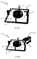
- FIG. 2D is shown as the pan support, in which the thermochromic material indicates a temperature, for example, below 50 ° C or advantageously below 45 ° C shown.
- the FIG. 3 shows a second embodiment of a pot carrier.
- the presentation in the FIG. 3 is a section of the pot carrier 11 with a finger 3, the vertical portion 4 is connected to the pot carrier frame 2.
- a recess 12 is provided in the manner of a bore.
- the bore may be, for example, a round bore or pot bore and allows the use of a display element in the pot carrier 11.
- the bore can pierce the pot carrier 11 completely, so that, for example, a cylindrical pin of thermosetting plastic with thermochromic pigments can be used as a display element. For the operator, a display point on the vertical section 4 of the pot carrier 11 is visible.
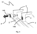
- FIG. 4 shows a third embodiment of a pot carrier.
- the pot carrier 13 in turn has a wedge-shaped recess on a vertical section 4 of a finger 3 in the region 15.
- a correspondingly shaped plastic part 14 can be used as a display element.
- the display element 14 may alternatively be clipped as a clip to a vertical portion 4 of the pot carrier. Then no recess is required. With a clip, there is the advantage that even delivered and used pot carriers can be retrofitted with a display element 14 in order to increase the safety for the operator. In the FIG. 4 is indicated by the arrow P as the display element 14 is removable from the pot carrier.
- the proposed pot carrier with an area comprising a thermochromic material safe and reliable by a color change in a temperature window, which may be determined by the choice of material mixture, a secure temperature display for an operator achieved.
- a thermochromic material safe and reliable by a color change in a temperature window, which may be determined by the choice of material mixture, a secure temperature display for an operator achieved.
Landscapes
- Engineering & Computer Science (AREA)
- Chemical & Material Sciences (AREA)
- Combustion & Propulsion (AREA)
- Mechanical Engineering (AREA)
- General Engineering & Computer Science (AREA)
- Cookers (AREA)
- Baking, Grill, Roasting (AREA)
Description
- Die vorliegende Erfindung betrifft einen Topfträger für einen Gasbrenner sowie eine Gaskochstelle. Topfträger sind um einen Gasbrenner angeordnet, um eine Auflagefläche für Gargutbehälter zu schaffen.
- Bekannte Topfträger sind in der Regel als umlaufender Rahmen mit nach innen tragenden Fingern ausgeführt, wobei die Finger die Auflagefläche schaffen.
- Beim Betrieb der Gaskochstelle heizen die Gasflammen sowohl das Kochgeschirr wie auch den Topfträger auf. Bevor nach einem Kochvorgang der entsprechende Gasherd sowie die Topfträger gereinigt werden können, muss die Bedienperson abwarten bis der Topfträger abgekühlt ist, um sich nicht zu verletzen. Bei bekannten Topfträgern ist die Bedienperson dabei auf ihre Erfahrung angewiesen, um abzuschätzen, ob der Topfträger noch eine Temperatur aufweist, die zu Verbrennungen beim Berühren beispielsweise mit ungeschützten Händen führen kann.
- Die
US 2004/0004069 beschreibt einen Topfträger mit einem Rahmen. Oberseitig an dem Rahmen sind Bereiche mit thermochromen Material vorgesehen. - Die
US 2002/0113057 A1 beschreibt eine Sicherheitseinrichtung mit einem thermochromen Material zur Warnung vor einer zu hohen Temperatur von heißen Oberflächen. - Vor diesem Hintergrund ist es eine Aufgabe der vorliegenden Erfindung, einen verbesserten Topfträger für eine Gaskochstelle bereitzustellen.
- Demgemäß wird ein Topfträger für einen Gasbrenner vorgeschlagen, bei dem in mindestens einem Bereich des Topfträgers ein thermochromes Material angeordnet ist.
- Dabei umfasst der Topfträger einen Rahmen als Standfläche des Topfträgers in oder auf einer Kochmulde und mehrere von dem Rahmen nach innen ragende Finger, deren Oberseiten eine Auflagefläche für einen Gargutbehälter bilden, wobei der Bereich an einem vertikalen Abschnitt eines der Finger angeordnet ist.
- Thermochrome Materialien ändern ihr äußeres Aussehen in Abhängigkeit von der vorliegenden Temperatur. Durch einen Farbumschlag von niedriger Temperatur zu einer hohen Temperatur kann dem Bediener einer Gaskochstelle, die mit einem entsprechenden Topfträger ausgestattet ist, angezeigt werden, ob der Topfträger noch eine Temperatur aufweist, die für ein Berühren beispielsweise mit bloßen Händen zu hoch ist. Insofern kann das thermochrome Material derart ausgewählt werden, dass es bei einer Temperatur des Topfträgers, die höher ist als eine Schwelltemperatur, in einer ersten Farbe erscheint und bei einer Topfträgertemperatur, die unterhalb der Schwelltemperatur liegt, in einer zweiten Farbe. Die Schwelltemperatur wird beispielsweise als eine Temperatur gewählt, bei der keine Verbrennung oder Verletzung der menschlichen Haut bei Berührung mehr erfolgt. Es sind auch mehrstufige Farbübergänge möglich.
- Bei einer Ausführungsform des Topfträgers ist das thermochrome Material in einer Ausnehmung an dem vertikalen Abschnitt eines der Finger angeordnet. Die Ausnehmung kann beispielsweise eine Bohrung oder ein entfernter Bereich einer Topfträgerleiste sein. Wenn das thermochrome Material beispielsweise in der Art eines Lackes oder eines Kunststoffes in eine Ausnehmung eingebracht ist, wird ein ästhetisch besonders günstiger Gesamteindruck erzielt.
- Denkbar ist auch, dass das thermochrome Material als ein abnehmbares Anzeigeelement in oder an dem vertikalen Abschnitt eines der Finger befestigt ist. Insofern kann das thermochrome Material als Anzeigeelement auch auf bestehende Topfträger angebracht werden oder nachgerüstet werden, um dem Bediener eine zu hohe Temperatur des Topfträgers anzuzeigen.
- In einer Ausführungsform ist das Anzeigeelement beispielsweise als ein Klipp ausgeführt. Ein Klipp ist dann zum Beispiel an einen Finger oder an eine Leiste des Topfträgers angeklippt.
- In einer bevorzugten Ausführungsform des Topfträgers ist der Bereich mit dem thermochromen Material bei bestimmungsgemäßem Einsatz des Topfträgers an einer Seite des vertikalen Abschnitts eines der Finger angeordnet, welche von dem Gasbrenner abgewandt ist.
- Ist der Bereich bzw. der Anzeigebereich oder das Anzeigeelement von der von dem Gasbrenner und insbesondere den Gasbrennerflammen abgewandten Seite angebracht oder angeordnet, befindet es sich im Hitzeschatten des Gasbrenners bei Betrieb. In der Regel sind dies die Stellen am Topfträger, welche von dem Bediener angefasst werden, um beispielsweise einen Reinigungsvorgang einzuleiten. Man spricht auch von einem Hitzeschatten, der in der Regel der kälteste Punkt des Topfträgers auch beim Betrieb des Gasbrenners ist.
- Bei noch einer Ausführungsform des Topfträgers ist das thermochrome Material als ein duroplastisches Kunststoffmaterial ausgebildet. Duroplastische Kunststoffe sind in der Regel quervernetzte Polymere. Im Gegensatz zu Thermoplasten sind sie nicht schmelzbar oder verformbar. Es sind thermochrome Duroplaste bekannt, in die thermochrome Pigmente als thermochrome Materialien eingearbeitet sind. Insofern kann bei der Herstellung des Duroplastes, welches beispielsweise als Anzeigeelement eingesetzt wird oder in eine Ausnehmung des Topfträgers eingelassen wird, bereits das Pigent mit themochromen Eigenschaften zugesetzt werden. Übliche thermochrome Pigmente lassen sich mit ein- und mehrstufigen Farbschaltungen insbesondere in Temperaturbereichen zwischen 0°C und 100°C herstellen.
- Vorzugsweise hat das thermochrome Material einen Farbumschlag in einem Temperaturbereich zwischen 40°C und 70°C. Es können jedoch auch andere Temperaturumschlagsbereiche verwendet werden. In der Regel sind Temperaturen zwischen 40°C und 60°C, und insbesondere zwischen 40°C und 45°C ausreichend sicher, damit keine Verbrennung bei Kontakt mit einem Material der entsprechenden Temperatur erfolgt.
- Das thermochrome Material hat vorzugsweise eine Temperaturbeständigkeit bis 450°C. In einer weiteren Ausführungsform hat das thermochrome Material eine Temperaturbeständigkeit bis 400°C. Die genannten Temperaturen entsprechen in etwa den durch Gasbrenner an Topfträgern verursachten Temperaturen.
- Der Topfträger umfasst einen Topfträgerrahmen als Standfläche des Topfträgers in oder auf einer Kochmulde und weist ferner mehrere von dem Rahmen nach innen ragende Finger auf. Die Oberseiten der Finger bilden eine Auflagefläche für einen Gargutbehälter.
- Der Bereich (mit dem thermochromen Material) ist an einem vertikalen Abschnitt eines der Finger angeordnet. Dadurch wird erreicht, dass die in der Regel zum Entnehmen oder Entfernen des Topfträgers von einer Gaskochstelle oder einer Gaskochmulde verwendete Abschnitte hinsichtlich ihrer Temperatureigenschaften durch das thermochrome Material charakterisiert werden. Der Bediener erkennt bei einem Farbumschlag in Richtung zu der Temperatur, die einen sicheren Farbtemperaturbereich anzeigt, dass ein Entnehmen an der Stelle sicher ist.
- Vorzugsweise ist der Bereich an einer Außenseite eines der Finger angeordnet.
- Ferner wird eine Gaskochstelle mit mindestens einem Gasbrenner und einem Topfträger wie vorbeschrieben vorgeschlagen.
- Bei einer Ausführungsform der Gaskochstelle sind der Gasbrenner und der Topfträger auf einer Kochfläche oder in einer Kochmulde angeordnet. Die Topfträger sind derart angeordnet, dass der Bereich mit dem thermochromen Material von einer Bedienposition des Bedieners der Gaskochstelle sichtbar ist. Dadurch kann beim Benutzen der Gaskochstelle die Bedienperson jederzeit feststellen, ob der Topfträger eine Temperatur hat, die zu hoch ist, um den Topfträger anzufassen.
- Bei den vorgeschlagenen Maßnahmen zur Anzeige der Temperatur eines Topfträgers durch Bereiche mit thermochromen Materialien oder einem Anzeigeelement wird keine zusätzliche Energie benötigt. Es sind auch keine elektrischen oder andere Sensoren notwendig, um bei Gasherden, die in der Regel keine Spannungsversorgung haben, elektrische Anzeigen für die Temperatur der Topfträger vorzusehen. Ferner ist der Farbumschlag reversibel, so dass die Anzeige der Temperatur des Topfträgers immer wieder erfolgen kann.
- Außerdem wird ein Gasherd mit einer oder mehreren Gaskochstellen, welche die vorbeschriebenen Topfträger umfasst vorgeschlagen. Der Gasherd kann dabei als Standgerät mit einem Unterschrank oder auch als Einbaugaskochmulde ausgeführt sein.
- Weitere mögliche Implementierungen der Erfindung umfassen auch nicht explizit genannte Kombinationen von zuvor oder im Folgenden bezüglich der Ausführungsbeispiele beschriebenen Merkmalen. Dabei wird der Fachmann auch Einzelaspekte als Verbesserungen oder Ergänzungen zu der jeweiligen Grundform des Topfträgers oder der Kochstelle hinzufügen.
- Weitere vorteilhafte Ausgestaltungen und Aspekte der Erfindung sind Gegenstand der Unteransprüche sowie der im Folgenden beschriebenen Ausführungsbeispiele der Erfindung. Im Weiteren wird die Erfindung anhand von bevorzugten Ausführungsformen unter Bezugnahme auf die beigelegten Figuren näher erläutert.
- Es zeigt dabei:
- Figur 1:
- eine Ausführungsform eines Topfträgers in perspektivischer Ansicht;
- Figur 2:
- eine Ausführungsform einer Gaskochstelle mit einem Gasbrenner in perspektivischer Ansicht;
- Figur 3:
- eine zweite Ausführungsform eines Topfträgers in perspektivischer Ansicht; und
- Figur 4:
- eine dritte Ausführungsform eines Topfträgers in perspektivischer Ansicht.
- In den Figuren sind gleiche oder funktionsgleiche Elemente mit denselben Bezugszeichen versehen, sofern nichts anderes angegeben ist.
- Die
Figur 1 zeigt eine perspektivische Darstellung einer Ausführungsform eines Topfträgers. Der Topfträger 1 umfasst dabei einen umlaufenden Topfträgerrahmen 2, der eine Standfläche SF bildet, mit der der Topfträger 1 in der Regel auf eine Gaskochmulde, einen Gasherd oder ein Gaskochfeld gesetzt wird. Von dem Rahmen 2 ragen Finger 3, die jeweils einen vertikalen Abschnitt 4 umfassen, in das Innere des Rahmens 2. Die Oberseiten der Finger 3 schaffen eine Auflagefläche AF für Kochgeschirr. - Die
Figur 1 zeigt ferner einen Bereich 5 des Topfträgers 1, in dem ein thermochromes Material vorgesehen ist. Der Bereich 5 mit dem thermochromen Material ist an der Außenseite eines der vertikalen Abschnitte 4 eines der Finger 3 vorgesehen. Beim Betrieb eines Gasbrenners im Inneren des Topfträgers 1 liegt der Bereich 5 mit dem thermochromen Material im Hitzeschatten. Üblicherweise wird der Topfträger auch an diesen Stellen von Bedienpersonen angefasst. - Das thermochrome Material ändert seine Farbe reversibel in Abhängigkeit von der Temperatur. Der Temperaturbereich ist daher im Wesentlichen zwischen Raumtemperatur (etwa 20°C - 30°C) und 40°C bis 70°C gewählt. In diesem Temperaturfenster ändert der beispielsweise als thermochrome Kunststoff vorgesehene Bereich 5 seine Farbe. Beispielsweise kann ein Farbumschlag von blau zu rot durch die Wahl der Materialmischungen von thermochromen Pigmenten in dem Kunststoff eingestellt werden. Beispielsweise wird eine Signalfarbe rot für hohe Temperaturen beispielsweise oberhalb von 50°C gewählt, um dem Nutzer anzuzeigen, dass der Topfträger nicht ungeschützt berührt werden sollte.
- Insbesondere bei Gaskochmulden mit Gasbrennern ist diese Hitzeanzeige am Topfträger von Vorteil, da die Topfträger während des Kochvorgangs verschmutzen können und häufig gereinigt werden müssen. Im Gegensatz zu Elektroherden oder Elektrokochmulden mit glatten Glaskeramikflächen der Elektroherde können die Elemente von Gaskochstellen nicht derart leicht gereinigt werden. Bei Gasherden ist in der Regel ein Entfernen des Topfträgers für den Reinigungsvorgang notwendig. Um dem Benutzer potenziell gefährlich erhitzte Topfträger beispielsweise aus Metall anzuzeigen, ist der Bereich 5 mit thermochromen Material vorgesehen. Damit wird die Gefahr eines Verbrennens oder Verletzens durch heiße Topfträger reduziert.
- Als Materialien für thermochrome Pigmente oder thermochrome Materialien eignen sich insbesondere duroplastische Kunststoffe, die wärmestabil sind. Bei duroplastischen Kunststoffen werden in der Regel quervernetzte Polymere eingesetzt und mit speziell entwickelten thermochromen Pigmenten versetzt. Es sind dabei mehrstufige Farbänderungen, die reversibel sind, denkbar. Der thermochrome Bereich 5, wie er in der
Figur 1 dargestellt ist, kann abnehmbar als Anzeigeelement ausgeführt sein oder aber auch in einer Ausnehmung in dem Topfträger vorgesehen sein. - Die
Figur 2 zeigt eine Ausführungsform einer Gaskochstelle mit einem Gasbrenner und einem Topfträger in perspektivischer Ansicht. Im Wesentlichen umfasst der Topfträger 1, welcher um einen Gasbrenner 6 angeordnet ist, dieselben Elemente wie es zu derFigur 1 erläutert wurde. DieFigur 2A zeigt die Gaskochstelle 10 mit einem brennenden Gasbrenner 6. Der Gasbrenner 6 hat dabei einen Gasbrennerkopf 7 mit Austrittsöffnungen für Gas, welches verbrennt und einen Kranz von Gasbrennerflammen 8 ausbildet. Die Gasflammen 8 strahlen Wärme ab und heizen den Topfträger 1 insbesondere an den Topfträgerfingern 3 auf. In der Darstellung derFigur 2A ist an einem vertikalen Abschnitt 4 des (in der Orientierung derFigur 2A ) rechten Fingers 3, ein Bereich mit thermochromem Material 5 vorgesehen. Das thermochrome Material, welches hier schraffiert dargestellt ist, zeigt mit seiner Farbe an, dass eine Aufheizung des Topfträgers erfolgt ist und ein Berühren beispielsweise mit einer Hand oder einem Finger gefährlich ist. Die Schraffur signalisiert beispielsweise eine rote Farbe, die als Warnung dient. - Selbst beim Ausschalten des Gasbrenners verbleibt der Topfträger eine gewisse Zeit aufgeheizt. Ohne ein Anzeigeelement mit thermochromen Material würde der Benutzer möglicherweise ahnungslos den Topfträger zum Reinigen anfassen und entfernen wollen. In der
Figur 2B ist der Gasbrenner 6 im ausgeschalteten Zustand angedeutet. Das Anzeigeelement 5 bzw. das thermochrome Material liegt jedoch noch immer in einem Zustand vor, in dem es die Temperatur des Topfträgers 1 oberhalb einer geeigneten Schwelltemperatur anzeigt. Erst nachdem der Topfträgern 1 und insbesondere der vertikale Abschnitt 4 des Fingers 3 abgekühlt ist, erfolgt ein Farbumschlag in Richtung zu einer beispielsweise Sicherheit andeutenden Farbe wie blau oder grün. Erst dann sollte ein Benutzer mit bloßen Händen den Topfträger anfassen. - In
Figur 2C ist der Farbumschlag des Anzeigeelementes 5 angedeutet, welches ohne Schraffur dargestellt ist. Nun ist es sicher für den Nutzer oder die Bedienperson, den Topfträger 1 beispielsweise zum Reinigen von der Kochstelle 10 zu entfernen. In derFigur 2D ist dargestellt, wie der Topfträger, bei dem das thermochrome Material eine Temperatur beispielsweise unterhalb von 50°C oder vorteilhafter Weise unterhalb von 45°C anzeigt, dargestellt. - Die
Figur 3 zeigt eine zweite Ausführungsform eines Topfträgers. Die Darstellung in derFigur 3 ist ein Ausschnitt des Topfträgers 11 mit einem Finger 3, dessen vertikaler Abschnitt 4 mit dem Topfträgerrahmen 2 verbunden ist. In dem vertikalen Abschnitt 4 ist eine Ausnehmung 12 in der Art einer Bohrung vorgesehen. Die Bohrung kann beispielsweise eine Rundbohrung oder Topfbohrung sein und erlaubt den Einsatz eines Anzeigeelementes in dem Topfträger 11. Dabei kann die Bohrung den Topfträger 11 vollständig durchstoßen, so dass beispielsweise ein zylindrischer Stift aus duroplastischem Kunststoff mit thermochromen Pigmenten als Anzeigeelement eingesetzt werden kann. Für den Bediener ist insofern ein Anzeigepunkt an dem vertikalen Abschnitt 4 des Topfträgers 11 sichtbar. - Die
Figur 4 zeigt eine dritte Ausführungsform eines Topfträgers. Der Topfträger 13 hat wiederum an einem vertikalen Abschnitt 4 eines Fingers 3 im Bereich 15 eine keilförmige Ausnehmung. In die Ausnehmung kann ein entsprechend geformtes Kunststoffteil 14 als Anzeigeelement eingesetzt werden. - Das Anzeigeelement 14 kann alternativ auch als Clip an einen vertikalen Abschnitt 4 des Topfträgers angeklippst werden. Dann ist keine Ausnehmung erforderlich. Bei einem Klipp besteht der Vorteil, dass auch bereits ausgelieferte und verwendete Topfträger mit einem Anzeigeelement 14 nachgerüstet werden können, um die Sicherheit für den Bediener zu erhöhen. In der
Figur 4 ist durch den Pfeil P angedeutet wie das Anzeigeelement 14 von dem Topfträger abnehmbar ist. - Durch den vorgeschlagenen Topfträger mit einem Bereich, der ein thermochromes Material umfasst, wird sicher und zuverlässig durch einen Farbumschlag in einem Temperaturfenster, das durch die Wahl der Materialmischung vorgegeben sein kann, eine sichere Temperaturanzeige für einen Bediener erzielt. Insgesamt wird insbesondere bei Gasherden, die mit entsprechenden Topfträgern ausgestattet sind, eine erhöhte Sicherheit erreicht, da der Bediener anhand der Farbe des Topfträgers bzw. des Bereiches mit dem thermochromen Material am oder im Topfträger erkennen kann, ob ein Anfassen gefahrlos möglich ist. Gasherde, die mit entsprechenden Topfträgern ausgestattet sind, sind also besonders sicher und bedienerfreundlich.
-
- 1
- Topfträger
- 2
- Rahmen
- 3
- Finger
- 4
- Fingerabschnitt
- 5
- Bereich
- 6
- Gasbrenner
- 7
- Brennerkopf
- 8
- Brennerflammen
- 9
- Bediener
- 10
- Gaskochstelle
- 11
- Topfträger
- 12
- Bohrung
- 13
- Topfträger
- 14A
- Anzeigelement
- 14B
- Klipp
- 15
- Bereich
- AF
- Auflagefläche
- SF
- Standfläche
- P
- Abnehmrichtung
Claims (13)
- Topfträger (1) für einen Gasbrenner (6), mit einem Rahmen als Standfläche (SF) in oder auf einer Kochmulde und mehreren von dem Rahmen nach innen ragenden Fingern (3), deren Oberseiten eine Auflagefläche (AF) für einen Gargutbehälter bilden, dadurch gekennzeichnet, dass in mindestens einem Bereich (5) des Topfträgers (1) an einem vertikalen Abschnitt (4) eines der Finger (3) ein thermochromes Material angeordnet ist.
- Topfträger (1) nach Anspruch 1, dadurch gekennzeichnet, dass das thermochrome Material in einer Ausnehmung an dem vertikalen Abschnitt (4) eines der Finger (3) angeordnet ist.
- Topfträger (1) nach Anspruch 1 oder 2, dadurch gekennzeichnet, dass das thermochrome Material als abnehmbares Anzeigeelement (14) in oder an dem vertikalen Abschnitt (4) eines der Finger (3) befestigt ist.
- Topfträger (1) nach Anspruch 3, dadurch gekennzeichnet, dass das Anzeigeelement (14B) als Klipp ausgeführt ist.
- Topfträger (11) nach einem der Ansprüche 1 - 4, dadurch gekennzeichnet, dass das thermochrome Material in einer Bohrung (12) in dem vertikalen Abschnitt (4) eines der Finger (3) befestigt ist
- Topfträger (1) nach einem der Ansprüche 1 - 5, dadurch gekennzeichnet, dass der Bereich (5) bei bestimmungsgemäßem Einsatz des Topfträgers (1) an einer Seite des vertikalen Abschnitts (4) eines der Finger (3) angeordnet ist, welche von dem Gasbrenner (6) abgewandt ist.
- Topfträger (1) nach einem der Ansprüche 1 - 6, dadurch gekennzeichnet, dass das thermochrome Material ein duroplastisches Kunststoffmaterial ist.
- Topfträger (1) nach einem der Ansprüche 1 - 7, dadurch gekennzeichnet, dass das thermochrome Material einen Farbumschlag in einem Temperaturbereich zwischen 40° C und 70° C hat.
- Topfträger (1) nach einem der Ansprüche 1 - 8, dadurch gekennzeichnet, dass das thermochrome Material eine Temperaturbeständigkeit zumindest bis 450° C hat.
- Topfträger (1) nach einem der Ansprüche 1 - 9, dadurch gekennzeichnet, dass der Bereich (5) an einer Außenseite eines der Finger (3) angeordnet ist.
- Gaskochstelle (10) mit mindestens einem Gasbrenner (6) und einem Topfträger (1) nach einem der Ansprüche 1 - 10.
- Gaskochstelle (10) nach Anspruch 11, dadurch gekennzeichnet, dass der Gasbrenner (6) und der Topfträger (1) auf einer Kochfläche oder in einer Kochmulde angeordnet sind und der Topfträger (1) derart angeordnet ist, dass der Bereich (5) mit dem thermochromen Material von einer Bedienposition eines Bedieners der Gaskochstelle (10) sichtbar ist.
- Gasherd mit mindestens einer Gaskochstelle (10) nach Anspruch 11 oder 12.
Applications Claiming Priority (2)
| Application Number | Priority Date | Filing Date | Title |
|---|---|---|---|
| DE201010042988 DE102010042988A1 (de) | 2010-10-27 | 2010-10-27 | Topfträger und Gaskochstelle |
| PCT/EP2011/067969 WO2012055709A2 (de) | 2010-10-27 | 2011-10-14 | Topfträger und gaskochstelle |
Publications (2)
| Publication Number | Publication Date |
|---|---|
| EP2633239A2 EP2633239A2 (de) | 2013-09-04 |
| EP2633239B1 true EP2633239B1 (de) | 2016-10-05 |
Family
ID=44862969
Family Applications (1)
| Application Number | Title | Priority Date | Filing Date |
|---|---|---|---|
| EP11771110.1A Not-in-force EP2633239B1 (de) | 2010-10-27 | 2011-10-14 | Topfträger und gaskochstelle |
Country Status (5)
| Country | Link |
|---|---|
| EP (1) | EP2633239B1 (de) |
| CN (1) | CN103154617A (de) |
| DE (1) | DE102010042988A1 (de) |
| RU (1) | RU2551603C2 (de) |
| WO (1) | WO2012055709A2 (de) |
Families Citing this family (5)
| Publication number | Priority date | Publication date | Assignee | Title |
|---|---|---|---|---|
| CN103123128A (zh) * | 2011-11-18 | 2013-05-29 | 博西华电器(江苏)有限公司 | 锅架、灶具用旋钮、灶具 |
| EP2816292A1 (de) * | 2013-06-21 | 2014-12-24 | BSH Bosch und Siemens Hausgeräte GmbH | Kochvorrichtung |
| WO2015151044A2 (en) * | 2014-04-04 | 2015-10-08 | Indesit Company S.P.A. | Grate for cookers |
| EP3268669B1 (de) | 2015-03-13 | 2020-04-22 | Whirlpool EMEA S.p.A | Topftragrost |
| US10610053B2 (en) | 2015-11-24 | 2020-04-07 | Sterno Products, Llc. | Portable stove for s'mores |
Family Cites Families (11)
| Publication number | Priority date | Publication date | Assignee | Title |
|---|---|---|---|---|
| FR2701543B1 (fr) * | 1993-02-15 | 1995-03-31 | Dietrich Europ Electromenager | Foyer à gaz dissociable à grille-support maintenue par le corps du brûleur. |
| DE20020984U1 (de) * | 2000-12-12 | 2001-05-03 | Schott Glas, 55122 Mainz | Kochfeld mit mindestens einem atmosphärischen Gasbrenner |
| US20040004069A1 (en) * | 2001-02-21 | 2004-01-08 | Lerner William S. | Heat warning devices directly applicable to hot surfaces |
| US6639190B2 (en) * | 2001-02-21 | 2003-10-28 | William S. Lerner | Heat alert safety device for smoothtop stoves and other hot surfaces |
| ITTO20020101U1 (it) * | 2002-05-20 | 2003-11-20 | Merloni Elettrodomestici Spa | Bruciatore di gas per piano di cottura domestico. |
| ITPS20030017A1 (it) * | 2003-04-18 | 2004-10-19 | So M I Press Societa Metalli I Niettati Spa | Corona perfezionata per bruciatori di fornelli a gas. |
| CN2636784Y (zh) * | 2003-07-23 | 2004-09-01 | 赖荧辉 | 锅具感温元件 |
| ITMI20041688A1 (it) * | 2004-09-01 | 2004-12-02 | Ballarini Paolo & Figli Spa | Recipiente per la cottura di cibi munito di decorazioni esterne |
| DE102005025896B4 (de) * | 2005-05-25 | 2010-11-25 | E.G.O. Elektro-Gerätebau GmbH | Kochfeldplatte mit optischer Temperaturanzeige und mit Vorrichtung zur optischen Temperaturerfassung sowie entsprechendes Kochfeld |
| CN201069400Y (zh) * | 2007-06-11 | 2008-06-04 | 陈少锋 | 烹饪器具警示感温片 |
| CN201602600U (zh) * | 2009-11-16 | 2010-10-13 | 浙江爱仕达电器股份有限公司 | 一种具有感温功能的锅 |
-
2010
- 2010-10-27 DE DE201010042988 patent/DE102010042988A1/de not_active Withdrawn
-
2011
- 2011-10-14 EP EP11771110.1A patent/EP2633239B1/de not_active Not-in-force
- 2011-10-14 RU RU2013122752/03A patent/RU2551603C2/ru not_active IP Right Cessation
- 2011-10-14 CN CN2011800519499A patent/CN103154617A/zh active Pending
- 2011-10-14 WO PCT/EP2011/067969 patent/WO2012055709A2/de not_active Ceased
Also Published As
| Publication number | Publication date |
|---|---|
| WO2012055709A3 (de) | 2012-06-21 |
| DE102010042988A1 (de) | 2012-05-03 |
| RU2013122752A (ru) | 2014-12-10 |
| RU2551603C2 (ru) | 2015-05-27 |
| CN103154617A (zh) | 2013-06-12 |
| EP2633239A2 (de) | 2013-09-04 |
| WO2012055709A2 (de) | 2012-05-03 |
Similar Documents
| Publication | Publication Date | Title |
|---|---|---|
| EP2633239B1 (de) | Topfträger und gaskochstelle | |
| EP0729292B1 (de) | Herdmulde | |
| EP3389457A1 (de) | GEFÄß MIT THERMOCHROMER INDIKATORBESCHICHTUNG | |
| DE2627373A1 (de) | Signaleinrichtung an kochgeraeten mit einer glaskeramikkochflaeche | |
| DE202004002435U1 (de) | Elektro-Ofen mit mehreren Funktionen | |
| DE60003700T2 (de) | Toastgerät mit einer erhitzungsvorrichtung für brötchen oder gleichartige nahrungsmittel | |
| DE202006012631U1 (de) | Grillvorrichtung zum Braten und/oder Garen von Speisen | |
| DE2932844C2 (de) | Einbau-Kochfeld | |
| DE19514261A1 (de) | Herdmulde | |
| DE202015105700U1 (de) | Vielzweckerhitzer | |
| DE3206024A1 (de) | Elektrokochplatte, vorzugsweise glaskeramik-kochmulde | |
| EP2327341A2 (de) | Kochgerät und insbesondere dafür vorgesehene(r) gelochte(r) GN-Behälter | |
| EP1593922A1 (de) | Brennofen | |
| EP2314934A2 (de) | Vorrichtung zur Aufnahme eines Gargutträgers für ein Hausgerät, Hausgerät, insbesondere Backofen, mit einer derartigen Vorrichtung sowie Verfahren zum Bedienen einer derartigen Vorrichtung | |
| DE2721921B2 (de) | Gas-Kocheinrichtung mit einer gasdichten Abdeckplatte | |
| EP2336647A2 (de) | Grillaufsatz für ein Gaskochfeld | |
| DE29905024U1 (de) | Kochanordnung | |
| EP0938859B1 (de) | Einrichtung zum Warmhalten von auf Tellern angeordneten warmen Speisen | |
| EP2072694B1 (de) | Spüle | |
| DE102016117695A1 (de) | Kochfeld | |
| DE19505801C2 (de) | Herdmulde mit einem Kochfeld, dem ein Auflageelement zum Auflegen von Grill- oder Bratgut zugeordnet ist | |
| DE102009000910A1 (de) | Bedien- und Anzeigevorrichtung für einen Herd oder Backofen | |
| DE814209C (de) | Topf zum Kochen, Braten, Backen oder Trocknen | |
| EP3210508A1 (de) | Elektrischer grill | |
| CH691756A5 (de) | Einrichtung zur Halterung von gewölbten Kochpfannen. |
Legal Events
| Date | Code | Title | Description |
|---|---|---|---|
| PUAI | Public reference made under article 153(3) epc to a published international application that has entered the european phase |
Free format text: ORIGINAL CODE: 0009012 |
|
| 17P | Request for examination filed |
Effective date: 20130527 |
|
| AK | Designated contracting states |
Kind code of ref document: A2 Designated state(s): AL AT BE BG CH CY CZ DE DK EE ES FI FR GB GR HR HU IE IS IT LI LT LU LV MC MK MT NL NO PL PT RO RS SE SI SK SM TR |
|
| DAX | Request for extension of the european patent (deleted) | ||
| RAP1 | Party data changed (applicant data changed or rights of an application transferred) |
Owner name: BSH HAUSGERAETE GMBH |
|
| GRAP | Despatch of communication of intention to grant a patent |
Free format text: ORIGINAL CODE: EPIDOSNIGR1 |
|
| INTG | Intention to grant announced |
Effective date: 20160510 |
|
| GRAS | Grant fee paid |
Free format text: ORIGINAL CODE: EPIDOSNIGR3 |
|
| GRAA | (expected) grant |
Free format text: ORIGINAL CODE: 0009210 |
|
| AK | Designated contracting states |
Kind code of ref document: B1 Designated state(s): AL AT BE BG CH CY CZ DE DK EE ES FI FR GB GR HR HU IE IS IT LI LT LU LV MC MK MT NL NO PL PT RO RS SE SI SK SM TR |
|
| REG | Reference to a national code |
Ref country code: GB Ref legal event code: FG4D Free format text: NOT ENGLISH |
|
| REG | Reference to a national code |
Ref country code: CH Ref legal event code: EP |
|
| REG | Reference to a national code |
Ref country code: AT Ref legal event code: REF Ref document number: 834998 Country of ref document: AT Kind code of ref document: T Effective date: 20161015 |
|
| REG | Reference to a national code |
Ref country code: IE Ref legal event code: FG4D Free format text: LANGUAGE OF EP DOCUMENT: GERMAN |
|
| REG | Reference to a national code |
Ref country code: DE Ref legal event code: R096 Ref document number: 502011010852 Country of ref document: DE |
|
| REG | Reference to a national code |
Ref country code: NL Ref legal event code: MP Effective date: 20161005 |
|
| REG | Reference to a national code |
Ref country code: LT Ref legal event code: MG4D |
|
| PG25 | Lapsed in a contracting state [announced via postgrant information from national office to epo] |
Ref country code: BE Free format text: LAPSE BECAUSE OF NON-PAYMENT OF DUE FEES Effective date: 20161031 Ref country code: LV Free format text: LAPSE BECAUSE OF FAILURE TO SUBMIT A TRANSLATION OF THE DESCRIPTION OR TO PAY THE FEE WITHIN THE PRESCRIBED TIME-LIMIT Effective date: 20161005 |
|
| PG25 | Lapsed in a contracting state [announced via postgrant information from national office to epo] |
Ref country code: GR Free format text: LAPSE BECAUSE OF FAILURE TO SUBMIT A TRANSLATION OF THE DESCRIPTION OR TO PAY THE FEE WITHIN THE PRESCRIBED TIME-LIMIT Effective date: 20170106 Ref country code: SE Free format text: LAPSE BECAUSE OF FAILURE TO SUBMIT A TRANSLATION OF THE DESCRIPTION OR TO PAY THE FEE WITHIN THE PRESCRIBED TIME-LIMIT Effective date: 20161005 Ref country code: LT Free format text: LAPSE BECAUSE OF FAILURE TO SUBMIT A TRANSLATION OF THE DESCRIPTION OR TO PAY THE FEE WITHIN THE PRESCRIBED TIME-LIMIT Effective date: 20161005 Ref country code: NO Free format text: LAPSE BECAUSE OF FAILURE TO SUBMIT A TRANSLATION OF THE DESCRIPTION OR TO PAY THE FEE WITHIN THE PRESCRIBED TIME-LIMIT Effective date: 20170105 |
|
| PG25 | Lapsed in a contracting state [announced via postgrant information from national office to epo] |
Ref country code: HR Free format text: LAPSE BECAUSE OF FAILURE TO SUBMIT A TRANSLATION OF THE DESCRIPTION OR TO PAY THE FEE WITHIN THE PRESCRIBED TIME-LIMIT Effective date: 20161005 Ref country code: IS Free format text: LAPSE BECAUSE OF FAILURE TO SUBMIT A TRANSLATION OF THE DESCRIPTION OR TO PAY THE FEE WITHIN THE PRESCRIBED TIME-LIMIT Effective date: 20170205 Ref country code: NL Free format text: LAPSE BECAUSE OF FAILURE TO SUBMIT A TRANSLATION OF THE DESCRIPTION OR TO PAY THE FEE WITHIN THE PRESCRIBED TIME-LIMIT Effective date: 20161005 Ref country code: ES Free format text: LAPSE BECAUSE OF FAILURE TO SUBMIT A TRANSLATION OF THE DESCRIPTION OR TO PAY THE FEE WITHIN THE PRESCRIBED TIME-LIMIT Effective date: 20161005 Ref country code: PL Free format text: LAPSE BECAUSE OF FAILURE TO SUBMIT A TRANSLATION OF THE DESCRIPTION OR TO PAY THE FEE WITHIN THE PRESCRIBED TIME-LIMIT Effective date: 20161005 Ref country code: PT Free format text: LAPSE BECAUSE OF FAILURE TO SUBMIT A TRANSLATION OF THE DESCRIPTION OR TO PAY THE FEE WITHIN THE PRESCRIBED TIME-LIMIT Effective date: 20170206 Ref country code: FI Free format text: LAPSE BECAUSE OF FAILURE TO SUBMIT A TRANSLATION OF THE DESCRIPTION OR TO PAY THE FEE WITHIN THE PRESCRIBED TIME-LIMIT Effective date: 20161005 Ref country code: RS Free format text: LAPSE BECAUSE OF FAILURE TO SUBMIT A TRANSLATION OF THE DESCRIPTION OR TO PAY THE FEE WITHIN THE PRESCRIBED TIME-LIMIT Effective date: 20161005 |
|
| REG | Reference to a national code |
Ref country code: CH Ref legal event code: PL |
|
| REG | Reference to a national code |
Ref country code: DE Ref legal event code: R097 Ref document number: 502011010852 Country of ref document: DE |
|
| REG | Reference to a national code |
Ref country code: IE Ref legal event code: MM4A |
|
| PG25 | Lapsed in a contracting state [announced via postgrant information from national office to epo] |
Ref country code: RO Free format text: LAPSE BECAUSE OF FAILURE TO SUBMIT A TRANSLATION OF THE DESCRIPTION OR TO PAY THE FEE WITHIN THE PRESCRIBED TIME-LIMIT Effective date: 20161005 Ref country code: DK Free format text: LAPSE BECAUSE OF FAILURE TO SUBMIT A TRANSLATION OF THE DESCRIPTION OR TO PAY THE FEE WITHIN THE PRESCRIBED TIME-LIMIT Effective date: 20161005 Ref country code: EE Free format text: LAPSE BECAUSE OF FAILURE TO SUBMIT A TRANSLATION OF THE DESCRIPTION OR TO PAY THE FEE WITHIN THE PRESCRIBED TIME-LIMIT Effective date: 20161005 Ref country code: CZ Free format text: LAPSE BECAUSE OF FAILURE TO SUBMIT A TRANSLATION OF THE DESCRIPTION OR TO PAY THE FEE WITHIN THE PRESCRIBED TIME-LIMIT Effective date: 20161005 Ref country code: SK Free format text: LAPSE BECAUSE OF FAILURE TO SUBMIT A TRANSLATION OF THE DESCRIPTION OR TO PAY THE FEE WITHIN THE PRESCRIBED TIME-LIMIT Effective date: 20161005 Ref country code: MC Free format text: LAPSE BECAUSE OF FAILURE TO SUBMIT A TRANSLATION OF THE DESCRIPTION OR TO PAY THE FEE WITHIN THE PRESCRIBED TIME-LIMIT Effective date: 20161005 Ref country code: LI Free format text: LAPSE BECAUSE OF NON-PAYMENT OF DUE FEES Effective date: 20161031 Ref country code: CH Free format text: LAPSE BECAUSE OF NON-PAYMENT OF DUE FEES Effective date: 20161031 |
|
| PLBE | No opposition filed within time limit |
Free format text: ORIGINAL CODE: 0009261 |
|
| STAA | Information on the status of an ep patent application or granted ep patent |
Free format text: STATUS: NO OPPOSITION FILED WITHIN TIME LIMIT |
|
| PG25 | Lapsed in a contracting state [announced via postgrant information from national office to epo] |
Ref country code: BG Free format text: LAPSE BECAUSE OF FAILURE TO SUBMIT A TRANSLATION OF THE DESCRIPTION OR TO PAY THE FEE WITHIN THE PRESCRIBED TIME-LIMIT Effective date: 20170105 Ref country code: SM Free format text: LAPSE BECAUSE OF FAILURE TO SUBMIT A TRANSLATION OF THE DESCRIPTION OR TO PAY THE FEE WITHIN THE PRESCRIBED TIME-LIMIT Effective date: 20161005 Ref country code: IT Free format text: LAPSE BECAUSE OF FAILURE TO SUBMIT A TRANSLATION OF THE DESCRIPTION OR TO PAY THE FEE WITHIN THE PRESCRIBED TIME-LIMIT Effective date: 20161005 Ref country code: LU Free format text: LAPSE BECAUSE OF NON-PAYMENT OF DUE FEES Effective date: 20161014 |
|
| REG | Reference to a national code |
Ref country code: FR Ref legal event code: ST Effective date: 20170804 |
|
| 26N | No opposition filed |
Effective date: 20170706 |
|
| GBPC | Gb: european patent ceased through non-payment of renewal fee |
Effective date: 20170105 |
|
| PG25 | Lapsed in a contracting state [announced via postgrant information from national office to epo] |
Ref country code: FR Free format text: LAPSE BECAUSE OF NON-PAYMENT OF DUE FEES Effective date: 20161205 |
|
| PG25 | Lapsed in a contracting state [announced via postgrant information from national office to epo] |
Ref country code: GB Free format text: LAPSE BECAUSE OF NON-PAYMENT OF DUE FEES Effective date: 20170105 Ref country code: SI Free format text: LAPSE BECAUSE OF FAILURE TO SUBMIT A TRANSLATION OF THE DESCRIPTION OR TO PAY THE FEE WITHIN THE PRESCRIBED TIME-LIMIT Effective date: 20161005 Ref country code: IE Free format text: LAPSE BECAUSE OF NON-PAYMENT OF DUE FEES Effective date: 20161014 |
|
| REG | Reference to a national code |
Ref country code: BE Ref legal event code: MM Effective date: 20161031 |
|
| REG | Reference to a national code |
Ref country code: AT Ref legal event code: MM01 Ref document number: 834998 Country of ref document: AT Kind code of ref document: T Effective date: 20161014 |
|
| PG25 | Lapsed in a contracting state [announced via postgrant information from national office to epo] |
Ref country code: AT Free format text: LAPSE BECAUSE OF NON-PAYMENT OF DUE FEES Effective date: 20161014 |
|
| PG25 | Lapsed in a contracting state [announced via postgrant information from national office to epo] |
Ref country code: CY Free format text: LAPSE BECAUSE OF FAILURE TO SUBMIT A TRANSLATION OF THE DESCRIPTION OR TO PAY THE FEE WITHIN THE PRESCRIBED TIME-LIMIT Effective date: 20161005 Ref country code: HU Free format text: LAPSE BECAUSE OF FAILURE TO SUBMIT A TRANSLATION OF THE DESCRIPTION OR TO PAY THE FEE WITHIN THE PRESCRIBED TIME-LIMIT; INVALID AB INITIO Effective date: 20111014 |
|
| PG25 | Lapsed in a contracting state [announced via postgrant information from national office to epo] |
Ref country code: MT Free format text: LAPSE BECAUSE OF FAILURE TO SUBMIT A TRANSLATION OF THE DESCRIPTION OR TO PAY THE FEE WITHIN THE PRESCRIBED TIME-LIMIT Effective date: 20161005 Ref country code: MK Free format text: LAPSE BECAUSE OF FAILURE TO SUBMIT A TRANSLATION OF THE DESCRIPTION OR TO PAY THE FEE WITHIN THE PRESCRIBED TIME-LIMIT Effective date: 20161005 |
|
| PG25 | Lapsed in a contracting state [announced via postgrant information from national office to epo] |
Ref country code: TR Free format text: LAPSE BECAUSE OF FAILURE TO SUBMIT A TRANSLATION OF THE DESCRIPTION OR TO PAY THE FEE WITHIN THE PRESCRIBED TIME-LIMIT Effective date: 20161005 |
|
| PGFP | Annual fee paid to national office [announced via postgrant information from national office to epo] |
Ref country code: DE Payment date: 20191031 Year of fee payment: 9 |
|
| PG25 | Lapsed in a contracting state [announced via postgrant information from national office to epo] |
Ref country code: AL Free format text: LAPSE BECAUSE OF FAILURE TO SUBMIT A TRANSLATION OF THE DESCRIPTION OR TO PAY THE FEE WITHIN THE PRESCRIBED TIME-LIMIT Effective date: 20161005 |
|
| REG | Reference to a national code |
Ref country code: DE Ref legal event code: R119 Ref document number: 502011010852 Country of ref document: DE |
|
| PG25 | Lapsed in a contracting state [announced via postgrant information from national office to epo] |
Ref country code: DE Free format text: LAPSE BECAUSE OF NON-PAYMENT OF DUE FEES Effective date: 20210501 |