EP2632406B1 - Reduced-pressure systems, dressings, and methods employing a wireless pump - Google Patents
Reduced-pressure systems, dressings, and methods employing a wireless pump Download PDFInfo
- Publication number
- EP2632406B1 EP2632406B1 EP11738356.2A EP11738356A EP2632406B1 EP 2632406 B1 EP2632406 B1 EP 2632406B1 EP 11738356 A EP11738356 A EP 11738356A EP 2632406 B1 EP2632406 B1 EP 2632406B1
- Authority
- EP
- European Patent Office
- Prior art keywords
- pressure
- pump
- reduced
- processor
- micro
- Prior art date
- Legal status (The legal status is an assumption and is not a legal conclusion. Google has not performed a legal analysis and makes no representation as to the accuracy of the status listed.)
- Active
Links
- 238000000034 method Methods 0.000 title claims description 22
- 230000002829 reductive effect Effects 0.000 claims description 94
- 238000007789 sealing Methods 0.000 claims description 94
- 239000012530 fluid Substances 0.000 claims description 69
- 238000009826 distribution Methods 0.000 claims description 66
- 230000002745 absorbent Effects 0.000 claims description 61
- 239000002250 absorbent Substances 0.000 claims description 61
- 230000004044 response Effects 0.000 claims description 14
- 230000008878 coupling Effects 0.000 claims description 11
- 238000010168 coupling process Methods 0.000 claims description 11
- 238000005859 coupling reaction Methods 0.000 claims description 11
- 238000004519 manufacturing process Methods 0.000 claims description 9
- 230000003213 activating effect Effects 0.000 claims description 6
- 210000001519 tissue Anatomy 0.000 description 100
- 239000000463 material Substances 0.000 description 30
- 239000007788 liquid Substances 0.000 description 23
- 206010052428 Wound Diseases 0.000 description 16
- 208000027418 Wounds and injury Diseases 0.000 description 15
- 230000006870 function Effects 0.000 description 12
- 238000004891 communication Methods 0.000 description 11
- 239000000835 fiber Substances 0.000 description 11
- 230000002209 hydrophobic effect Effects 0.000 description 10
- 239000006260 foam Substances 0.000 description 9
- 230000008901 benefit Effects 0.000 description 8
- 210000000416 exudates and transudate Anatomy 0.000 description 8
- 239000007789 gas Substances 0.000 description 8
- 210000002615 epidermis Anatomy 0.000 description 7
- 239000003610 charcoal Substances 0.000 description 6
- 230000004913 activation Effects 0.000 description 5
- 230000000670 limiting effect Effects 0.000 description 5
- 230000010355 oscillation Effects 0.000 description 5
- 238000002560 therapeutic procedure Methods 0.000 description 5
- 230000010261 cell growth Effects 0.000 description 4
- 229920001971 elastomer Polymers 0.000 description 4
- 238000005516 engineering process Methods 0.000 description 4
- -1 open-cell Polymers 0.000 description 4
- 238000003860 storage Methods 0.000 description 4
- 239000000126 substance Substances 0.000 description 4
- 229920000954 Polyglycolide Polymers 0.000 description 3
- 239000000853 adhesive Substances 0.000 description 3
- 230000001070 adhesive effect Effects 0.000 description 3
- 239000003990 capacitor Substances 0.000 description 3
- 238000010586 diagram Methods 0.000 description 3
- 239000000806 elastomer Substances 0.000 description 3
- 238000003306 harvesting Methods 0.000 description 3
- 239000000203 mixture Substances 0.000 description 3
- 235000019645 odor Nutrition 0.000 description 3
- 230000002572 peristaltic effect Effects 0.000 description 3
- 239000004633 polyglycolic acid Substances 0.000 description 3
- 239000004814 polyurethane Substances 0.000 description 3
- 230000000717 retained effect Effects 0.000 description 3
- 230000001225 therapeutic effect Effects 0.000 description 3
- 101100014709 Drosophila melanogaster wisp gene Proteins 0.000 description 2
- 239000004698 Polyethylene Substances 0.000 description 2
- 238000010521 absorption reaction Methods 0.000 description 2
- 230000004075 alteration Effects 0.000 description 2
- 230000005540 biological transmission Effects 0.000 description 2
- 230000008859 change Effects 0.000 description 2
- 239000000499 gel Substances 0.000 description 2
- 230000037361 pathway Effects 0.000 description 2
- 230000035699 permeability Effects 0.000 description 2
- 229920000573 polyethylene Polymers 0.000 description 2
- 239000004626 polylactic acid Substances 0.000 description 2
- 229920000642 polymer Polymers 0.000 description 2
- 229920001296 polysiloxane Polymers 0.000 description 2
- 238000012545 processing Methods 0.000 description 2
- 230000001681 protective effect Effects 0.000 description 2
- 238000005086 pumping Methods 0.000 description 2
- 238000011160 research Methods 0.000 description 2
- 206010003445 Ascites Diseases 0.000 description 1
- 235000014653 Carica parviflora Nutrition 0.000 description 1
- 241000243321 Cnidaria Species 0.000 description 1
- 102000008186 Collagen Human genes 0.000 description 1
- 108010035532 Collagen Proteins 0.000 description 1
- 229920002943 EPDM rubber Polymers 0.000 description 1
- 229920000181 Ethylene propylene rubber Polymers 0.000 description 1
- 206010063560 Excessive granulation tissue Diseases 0.000 description 1
- 244000043261 Hevea brasiliensis Species 0.000 description 1
- 241001465754 Metazoa Species 0.000 description 1
- 229920000459 Nitrile rubber Polymers 0.000 description 1
- 239000005062 Polybutadiene Substances 0.000 description 1
- 239000004820 Pressure-sensitive adhesive Substances 0.000 description 1
- 229920001247 Reticulated foam Polymers 0.000 description 1
- 210000000683 abdominal cavity Anatomy 0.000 description 1
- 230000009471 action Effects 0.000 description 1
- 210000000577 adipose tissue Anatomy 0.000 description 1
- 230000002411 adverse Effects 0.000 description 1
- 230000000844 anti-bacterial effect Effects 0.000 description 1
- 229940088710 antibiotic agent Drugs 0.000 description 1
- 238000013459 approach Methods 0.000 description 1
- 230000004888 barrier function Effects 0.000 description 1
- 239000000560 biocompatible material Substances 0.000 description 1
- 230000015572 biosynthetic process Effects 0.000 description 1
- 210000001124 body fluid Anatomy 0.000 description 1
- 239000010839 body fluid Substances 0.000 description 1
- 210000000988 bone and bone Anatomy 0.000 description 1
- 229920005549 butyl rubber Polymers 0.000 description 1
- 229910000389 calcium phosphate Inorganic materials 0.000 description 1
- 239000001506 calcium phosphate Substances 0.000 description 1
- 235000011010 calcium phosphates Nutrition 0.000 description 1
- 150000004649 carbonic acid derivatives Chemical class 0.000 description 1
- 210000000845 cartilage Anatomy 0.000 description 1
- 238000005266 casting Methods 0.000 description 1
- 230000001413 cellular effect Effects 0.000 description 1
- 229920001436 collagen Polymers 0.000 description 1
- 239000002131 composite material Substances 0.000 description 1
- 210000002808 connective tissue Anatomy 0.000 description 1
- 238000005520 cutting process Methods 0.000 description 1
- 230000001419 dependent effect Effects 0.000 description 1
- 238000013461 design Methods 0.000 description 1
- 229940079593 drug Drugs 0.000 description 1
- 239000003814 drug Substances 0.000 description 1
- 230000002500 effect on skin Effects 0.000 description 1
- 230000005489 elastic deformation Effects 0.000 description 1
- 239000013536 elastomeric material Substances 0.000 description 1
- 239000005038 ethylene vinyl acetate Substances 0.000 description 1
- 239000002657 fibrous material Substances 0.000 description 1
- 238000009472 formulation Methods 0.000 description 1
- 210000001126 granulation tissue Anatomy 0.000 description 1
- 230000012010 growth Effects 0.000 description 1
- 239000003102 growth factor Substances 0.000 description 1
- 230000035876 healing Effects 0.000 description 1
- 230000002706 hydrostatic effect Effects 0.000 description 1
- 125000002887 hydroxy group Chemical group [H]O* 0.000 description 1
- 229920002681 hypalon Polymers 0.000 description 1
- 238000005286 illumination Methods 0.000 description 1
- 238000001802 infusion Methods 0.000 description 1
- 238000009434 installation Methods 0.000 description 1
- 230000002452 interceptive effect Effects 0.000 description 1
- 210000003041 ligament Anatomy 0.000 description 1
- 238000005259 measurement Methods 0.000 description 1
- 238000002483 medication Methods 0.000 description 1
- 238000012986 modification Methods 0.000 description 1
- 230000004048 modification Effects 0.000 description 1
- 210000003205 muscle Anatomy 0.000 description 1
- 229920003052 natural elastomer Polymers 0.000 description 1
- 229920001194 natural rubber Polymers 0.000 description 1
- 238000009581 negative-pressure wound therapy Methods 0.000 description 1
- 239000004745 nonwoven fabric Substances 0.000 description 1
- 230000003534 oscillatory effect Effects 0.000 description 1
- 206010033675 panniculitis Diseases 0.000 description 1
- 230000036961 partial effect Effects 0.000 description 1
- 230000002093 peripheral effect Effects 0.000 description 1
- 229920001084 poly(chloroprene) Polymers 0.000 description 1
- 229920000747 poly(lactic acid) Polymers 0.000 description 1
- 229920002857 polybutadiene Polymers 0.000 description 1
- 229920000515 polycarbonate Polymers 0.000 description 1
- 239000004417 polycarbonate Substances 0.000 description 1
- 229920000728 polyester Polymers 0.000 description 1
- 229920001195 polyisoprene Polymers 0.000 description 1
- 229920001021 polysulfide Polymers 0.000 description 1
- 239000005077 polysulfide Substances 0.000 description 1
- 150000008117 polysulfides Polymers 0.000 description 1
- 229920002635 polyurethane Polymers 0.000 description 1
- 239000011148 porous material Substances 0.000 description 1
- 230000009467 reduction Effects 0.000 description 1
- 239000005060 rubber Substances 0.000 description 1
- 238000005070 sampling Methods 0.000 description 1
- 229920006395 saturated elastomer Polymers 0.000 description 1
- 238000000638 solvent extraction Methods 0.000 description 1
- 125000006850 spacer group Chemical group 0.000 description 1
- 229920003048 styrene butadiene rubber Polymers 0.000 description 1
- 210000004304 subcutaneous tissue Anatomy 0.000 description 1
- 238000006467 substitution reaction Methods 0.000 description 1
- 239000013589 supplement Substances 0.000 description 1
- 210000002435 tendon Anatomy 0.000 description 1
- 238000012546 transfer Methods 0.000 description 1
- QORWJWZARLRLPR-UHFFFAOYSA-H tricalcium bis(phosphate) Chemical compound [Ca+2].[Ca+2].[Ca+2].[O-]P([O-])([O-])=O.[O-]P([O-])([O-])=O QORWJWZARLRLPR-UHFFFAOYSA-H 0.000 description 1
- 230000001960 triggered effect Effects 0.000 description 1
- 230000002792 vascular Effects 0.000 description 1
- 230000000007 visual effect Effects 0.000 description 1
- 238000003466 welding Methods 0.000 description 1
Images


Classifications
-
- A—HUMAN NECESSITIES
- A61—MEDICAL OR VETERINARY SCIENCE; HYGIENE
- A61M—DEVICES FOR INTRODUCING MEDIA INTO, OR ONTO, THE BODY; DEVICES FOR TRANSDUCING BODY MEDIA OR FOR TAKING MEDIA FROM THE BODY; DEVICES FOR PRODUCING OR ENDING SLEEP OR STUPOR
- A61M1/00—Suction or pumping devices for medical purposes; Devices for carrying-off, for treatment of, or for carrying-over, body-liquids; Drainage systems
- A61M1/80—Suction pumps
-
- A—HUMAN NECESSITIES
- A61—MEDICAL OR VETERINARY SCIENCE; HYGIENE
- A61F—FILTERS IMPLANTABLE INTO BLOOD VESSELS; PROSTHESES; DEVICES PROVIDING PATENCY TO, OR PREVENTING COLLAPSING OF, TUBULAR STRUCTURES OF THE BODY, e.g. STENTS; ORTHOPAEDIC, NURSING OR CONTRACEPTIVE DEVICES; FOMENTATION; TREATMENT OR PROTECTION OF EYES OR EARS; BANDAGES, DRESSINGS OR ABSORBENT PADS; FIRST-AID KITS
- A61F13/00—Bandages or dressings; Absorbent pads
- A61F13/00051—Accessories for dressings
- A61F13/00055—Saturation indicators
-
- A—HUMAN NECESSITIES
- A61—MEDICAL OR VETERINARY SCIENCE; HYGIENE
- A61F—FILTERS IMPLANTABLE INTO BLOOD VESSELS; PROSTHESES; DEVICES PROVIDING PATENCY TO, OR PREVENTING COLLAPSING OF, TUBULAR STRUCTURES OF THE BODY, e.g. STENTS; ORTHOPAEDIC, NURSING OR CONTRACEPTIVE DEVICES; FOMENTATION; TREATMENT OR PROTECTION OF EYES OR EARS; BANDAGES, DRESSINGS OR ABSORBENT PADS; FIRST-AID KITS
- A61F13/00—Bandages or dressings; Absorbent pads
- A61F13/02—Adhesive bandages or dressings
-
- A—HUMAN NECESSITIES
- A61—MEDICAL OR VETERINARY SCIENCE; HYGIENE
- A61F—FILTERS IMPLANTABLE INTO BLOOD VESSELS; PROSTHESES; DEVICES PROVIDING PATENCY TO, OR PREVENTING COLLAPSING OF, TUBULAR STRUCTURES OF THE BODY, e.g. STENTS; ORTHOPAEDIC, NURSING OR CONTRACEPTIVE DEVICES; FOMENTATION; TREATMENT OR PROTECTION OF EYES OR EARS; BANDAGES, DRESSINGS OR ABSORBENT PADS; FIRST-AID KITS
- A61F13/00—Bandages or dressings; Absorbent pads
- A61F13/05—Bandages or dressings; Absorbent pads specially adapted for use with sub-pressure or over-pressure therapy, wound drainage or wound irrigation, e.g. for use with negative-pressure wound therapy [NPWT]
-
- A—HUMAN NECESSITIES
- A61—MEDICAL OR VETERINARY SCIENCE; HYGIENE
- A61M—DEVICES FOR INTRODUCING MEDIA INTO, OR ONTO, THE BODY; DEVICES FOR TRANSDUCING BODY MEDIA OR FOR TAKING MEDIA FROM THE BODY; DEVICES FOR PRODUCING OR ENDING SLEEP OR STUPOR
- A61M1/00—Suction or pumping devices for medical purposes; Devices for carrying-off, for treatment of, or for carrying-over, body-liquids; Drainage systems
- A61M1/71—Suction drainage systems
- A61M1/73—Suction drainage systems comprising sensors or indicators for physical values
- A61M1/732—Visual indicating means for vacuum pressure
-
- A—HUMAN NECESSITIES
- A61—MEDICAL OR VETERINARY SCIENCE; HYGIENE
- A61M—DEVICES FOR INTRODUCING MEDIA INTO, OR ONTO, THE BODY; DEVICES FOR TRANSDUCING BODY MEDIA OR FOR TAKING MEDIA FROM THE BODY; DEVICES FOR PRODUCING OR ENDING SLEEP OR STUPOR
- A61M1/00—Suction or pumping devices for medical purposes; Devices for carrying-off, for treatment of, or for carrying-over, body-liquids; Drainage systems
- A61M1/90—Negative pressure wound therapy devices, i.e. devices for applying suction to a wound to promote healing, e.g. including a vacuum dressing
- A61M1/91—Suction aspects of the dressing
- A61M1/915—Constructional details of the pressure distribution manifold
-
- A—HUMAN NECESSITIES
- A61—MEDICAL OR VETERINARY SCIENCE; HYGIENE
- A61M—DEVICES FOR INTRODUCING MEDIA INTO, OR ONTO, THE BODY; DEVICES FOR TRANSDUCING BODY MEDIA OR FOR TAKING MEDIA FROM THE BODY; DEVICES FOR PRODUCING OR ENDING SLEEP OR STUPOR
- A61M1/00—Suction or pumping devices for medical purposes; Devices for carrying-off, for treatment of, or for carrying-over, body-liquids; Drainage systems
- A61M1/90—Negative pressure wound therapy devices, i.e. devices for applying suction to a wound to promote healing, e.g. including a vacuum dressing
- A61M1/95—Negative pressure wound therapy devices, i.e. devices for applying suction to a wound to promote healing, e.g. including a vacuum dressing with sensors for exudate composition
-
- A—HUMAN NECESSITIES
- A61—MEDICAL OR VETERINARY SCIENCE; HYGIENE
- A61M—DEVICES FOR INTRODUCING MEDIA INTO, OR ONTO, THE BODY; DEVICES FOR TRANSDUCING BODY MEDIA OR FOR TAKING MEDIA FROM THE BODY; DEVICES FOR PRODUCING OR ENDING SLEEP OR STUPOR
- A61M1/00—Suction or pumping devices for medical purposes; Devices for carrying-off, for treatment of, or for carrying-over, body-liquids; Drainage systems
- A61M1/90—Negative pressure wound therapy devices, i.e. devices for applying suction to a wound to promote healing, e.g. including a vacuum dressing
- A61M1/96—Suction control thereof
- A61M1/962—Suction control thereof having pumping means on the suction site, e.g. miniature pump on dressing or dressing capable of exerting suction
-
- A—HUMAN NECESSITIES
- A61—MEDICAL OR VETERINARY SCIENCE; HYGIENE
- A61M—DEVICES FOR INTRODUCING MEDIA INTO, OR ONTO, THE BODY; DEVICES FOR TRANSDUCING BODY MEDIA OR FOR TAKING MEDIA FROM THE BODY; DEVICES FOR PRODUCING OR ENDING SLEEP OR STUPOR
- A61M1/00—Suction or pumping devices for medical purposes; Devices for carrying-off, for treatment of, or for carrying-over, body-liquids; Drainage systems
- A61M1/90—Negative pressure wound therapy devices, i.e. devices for applying suction to a wound to promote healing, e.g. including a vacuum dressing
- A61M1/96—Suction control thereof
- A61M1/966—Suction control thereof having a pressure sensor on or near the dressing
-
- A—HUMAN NECESSITIES
- A61—MEDICAL OR VETERINARY SCIENCE; HYGIENE
- A61F—FILTERS IMPLANTABLE INTO BLOOD VESSELS; PROSTHESES; DEVICES PROVIDING PATENCY TO, OR PREVENTING COLLAPSING OF, TUBULAR STRUCTURES OF THE BODY, e.g. STENTS; ORTHOPAEDIC, NURSING OR CONTRACEPTIVE DEVICES; FOMENTATION; TREATMENT OR PROTECTION OF EYES OR EARS; BANDAGES, DRESSINGS OR ABSORBENT PADS; FIRST-AID KITS
- A61F13/00—Bandages or dressings; Absorbent pads
- A61F2013/00089—Wound bandages
- A61F2013/0017—Wound bandages possibility of applying fluid
- A61F2013/00174—Wound bandages possibility of applying fluid possibility of applying pressure
-
- A—HUMAN NECESSITIES
- A61—MEDICAL OR VETERINARY SCIENCE; HYGIENE
- A61F—FILTERS IMPLANTABLE INTO BLOOD VESSELS; PROSTHESES; DEVICES PROVIDING PATENCY TO, OR PREVENTING COLLAPSING OF, TUBULAR STRUCTURES OF THE BODY, e.g. STENTS; ORTHOPAEDIC, NURSING OR CONTRACEPTIVE DEVICES; FOMENTATION; TREATMENT OR PROTECTION OF EYES OR EARS; BANDAGES, DRESSINGS OR ABSORBENT PADS; FIRST-AID KITS
- A61F13/00—Bandages or dressings; Absorbent pads
- A61F2013/00361—Plasters
- A61F2013/00365—Plasters use
- A61F2013/00536—Plasters use for draining or irrigating wounds
-
- A—HUMAN NECESSITIES
- A61—MEDICAL OR VETERINARY SCIENCE; HYGIENE
- A61F—FILTERS IMPLANTABLE INTO BLOOD VESSELS; PROSTHESES; DEVICES PROVIDING PATENCY TO, OR PREVENTING COLLAPSING OF, TUBULAR STRUCTURES OF THE BODY, e.g. STENTS; ORTHOPAEDIC, NURSING OR CONTRACEPTIVE DEVICES; FOMENTATION; TREATMENT OR PROTECTION OF EYES OR EARS; BANDAGES, DRESSINGS OR ABSORBENT PADS; FIRST-AID KITS
- A61F13/00—Bandages or dressings; Absorbent pads
- A61F2013/00361—Plasters
- A61F2013/00902—Plasters containing means
- A61F2013/0094—Plasters containing means for sensing physical parameters
-
- A—HUMAN NECESSITIES
- A61—MEDICAL OR VETERINARY SCIENCE; HYGIENE
- A61M—DEVICES FOR INTRODUCING MEDIA INTO, OR ONTO, THE BODY; DEVICES FOR TRANSDUCING BODY MEDIA OR FOR TAKING MEDIA FROM THE BODY; DEVICES FOR PRODUCING OR ENDING SLEEP OR STUPOR
- A61M1/00—Suction or pumping devices for medical purposes; Devices for carrying-off, for treatment of, or for carrying-over, body-liquids; Drainage systems
- A61M1/71—Suction drainage systems
- A61M1/74—Suction control
- A61M1/75—Intermittent or pulsating suction
-
- A—HUMAN NECESSITIES
- A61—MEDICAL OR VETERINARY SCIENCE; HYGIENE
- A61M—DEVICES FOR INTRODUCING MEDIA INTO, OR ONTO, THE BODY; DEVICES FOR TRANSDUCING BODY MEDIA OR FOR TAKING MEDIA FROM THE BODY; DEVICES FOR PRODUCING OR ENDING SLEEP OR STUPOR
- A61M1/00—Suction or pumping devices for medical purposes; Devices for carrying-off, for treatment of, or for carrying-over, body-liquids; Drainage systems
- A61M1/90—Negative pressure wound therapy devices, i.e. devices for applying suction to a wound to promote healing, e.g. including a vacuum dressing
- A61M1/92—Negative pressure wound therapy devices, i.e. devices for applying suction to a wound to promote healing, e.g. including a vacuum dressing with liquid supply means
-
- A—HUMAN NECESSITIES
- A61—MEDICAL OR VETERINARY SCIENCE; HYGIENE
- A61M—DEVICES FOR INTRODUCING MEDIA INTO, OR ONTO, THE BODY; DEVICES FOR TRANSDUCING BODY MEDIA OR FOR TAKING MEDIA FROM THE BODY; DEVICES FOR PRODUCING OR ENDING SLEEP OR STUPOR
- A61M1/00—Suction or pumping devices for medical purposes; Devices for carrying-off, for treatment of, or for carrying-over, body-liquids; Drainage systems
- A61M1/90—Negative pressure wound therapy devices, i.e. devices for applying suction to a wound to promote healing, e.g. including a vacuum dressing
- A61M1/96—Suction control thereof
- A61M1/964—Suction control thereof having venting means on or near the dressing
-
- A—HUMAN NECESSITIES
- A61—MEDICAL OR VETERINARY SCIENCE; HYGIENE
- A61M—DEVICES FOR INTRODUCING MEDIA INTO, OR ONTO, THE BODY; DEVICES FOR TRANSDUCING BODY MEDIA OR FOR TAKING MEDIA FROM THE BODY; DEVICES FOR PRODUCING OR ENDING SLEEP OR STUPOR
- A61M2205/00—General characteristics of the apparatus
- A61M2205/33—Controlling, regulating or measuring
- A61M2205/3331—Pressure; Flow
- A61M2205/3344—Measuring or controlling pressure at the body treatment site
-
- A—HUMAN NECESSITIES
- A61—MEDICAL OR VETERINARY SCIENCE; HYGIENE
- A61M—DEVICES FOR INTRODUCING MEDIA INTO, OR ONTO, THE BODY; DEVICES FOR TRANSDUCING BODY MEDIA OR FOR TAKING MEDIA FROM THE BODY; DEVICES FOR PRODUCING OR ENDING SLEEP OR STUPOR
- A61M2205/00—General characteristics of the apparatus
- A61M2205/35—Communication
- A61M2205/3576—Communication with non implanted data transmission devices, e.g. using external transmitter or receiver
- A61M2205/3592—Communication with non implanted data transmission devices, e.g. using external transmitter or receiver using telemetric means, e.g. radio or optical transmission
-
- A—HUMAN NECESSITIES
- A61—MEDICAL OR VETERINARY SCIENCE; HYGIENE
- A61M—DEVICES FOR INTRODUCING MEDIA INTO, OR ONTO, THE BODY; DEVICES FOR TRANSDUCING BODY MEDIA OR FOR TAKING MEDIA FROM THE BODY; DEVICES FOR PRODUCING OR ENDING SLEEP OR STUPOR
- A61M2205/00—General characteristics of the apparatus
- A61M2205/60—General characteristics of the apparatus with identification means
- A61M2205/6054—Magnetic identification systems
-
- Y—GENERAL TAGGING OF NEW TECHNOLOGICAL DEVELOPMENTS; GENERAL TAGGING OF CROSS-SECTIONAL TECHNOLOGIES SPANNING OVER SEVERAL SECTIONS OF THE IPC; TECHNICAL SUBJECTS COVERED BY FORMER USPC CROSS-REFERENCE ART COLLECTIONS [XRACs] AND DIGESTS
- Y10—TECHNICAL SUBJECTS COVERED BY FORMER USPC
- Y10T—TECHNICAL SUBJECTS COVERED BY FORMER US CLASSIFICATION
- Y10T29/00—Metal working
- Y10T29/49—Method of mechanical manufacture
- Y10T29/49002—Electrical device making
- Y10T29/49016—Antenna or wave energy "plumbing" making
- Y10T29/49018—Antenna or wave energy "plumbing" making with other electrical component
Definitions
- Provisional Patent Application serial number 61/445,383 entitled “Interactive, Wireless Reduced-Pressure Dressings, Methods, and Systems," filed 22 February 2011, which is incorporated herein by reference for all purposes [VAC.0999PRO]; and U.S. Provisional Patent Application serial number 61/445,338 , entitled “Reduced-Pressure Systems, Dressings, and Methods Employing a Wireless Pump,” filed 22 February 2011, which is incorporated herein by reference for all purposes [VAC.1000PRO].
- the present disclosure relates generally to medical treatment systems and, more particularly, but not by way of limitation, to systems, dressings, and methods that involve wirelessly providing power to a pump that applies reduced pressure to a tissue site.
- KR 2002 0032508 describes a patch type infusion pump adjustable at a remote distance by using a wireless communication method to achieve an ultra light pump by eliminating the installation of manipulating switches or display elements.
- a system for treating a tissue site with reduced pressure includes a reduced-pressure dressing for disposing proximate to the tissue site and a wireless, reduced-pressure pump fluidly coupled to the reduced-pressure dressing.
- the wireless, reduced-pressure pump includes a Radio Frequency Identification (RFID) antenna, a first processor coupled to the RFID antenna, a micro-pump device coupled to the processor for receiving power and developing reduced pressure, a first pump-sealing member, a fluid reservoir, and a second pump-sealing member.
- the first pump-sealing member and second pump sealing are at least partially coupled to form a pump pouch in which the micro-pump is disposed.
- the system further includes a base unit having a RFID reader.
- the RFID reader is configured to provide power to the RFID antenna such that the micro-pump is powered.
- a method of manufacturing a system for treating a tissue site on a patient with reduced pressure includes providing a reduced-pressure dressing for disposing proximate to the tissue site and providing a wireless, reduced-pressure pump.
- the wireless, reduced-pressure pump includes a RFID antenna, a first processor coupled to the RFID antenna, a micro-pump device coupled to the first processor for receiving power and developing a reduced pressure, a first pump-sealing member, a fluid reservoir, and a second pump-sealing member.
- the first pump-sealing member and second pump sealing are at least partially coupled to form a pump pouch in which the micro-pump is disposed.
- the method may further include providing a reduced-pressure delivery conduit for fluidly coupling the wireless, reduced-pressure pump to the reduced-pressure dressing.
- the method further includes providing a base unit having a RFID reader.
- the RFID reader is configured to provide power to the RFID antenna such that the micro-pump is powered.
- RFID Radio Frequency Identification
- RFID Radio Frequency Identification
- RFID an enhanced type of Radio Frequency Identification
- RFID Radio Frequency Identification
- RFID RFID
- RFID tags include an integrated circuit for storing and processing information, a modulator, and demodulator.
- RFID tags can be passive tags, active RFID tags, and battery-assisted passive tags. Generally, passive tags use no battery and do not transmit information unless they are energized by a RFID reader.
- Active tags have an on-board battery and can transmit autonomously (i.e., without being energized by a RFID reader).
- Battery-assisted passive tags typically have a small battery on-board that is activated in the presence of a RFID reader.
- a microcontroller and sensor may be incorporated into the reduced-pressure dressing.
- the RFID tag, a microcontroller and sensor allow sensing and optional computational functions.
- the RFID tag and microcontroller partially or entirely power a micro-pump.
- the enhanced RFID technology is a Wireless Identification and Sensing Platform (WISP) device.
- WISPs involve powering and reading a WISP device, analogous to a RFID tag (or label), with a RFID reader.
- the WISP device harvests the power from the RFID reader's emitted radio signals and performs sensing functions (and optionally performs computational functions).
- the WISP device transmits a radio signal with information to the RFID reader.
- the WISP device receives power from the RFID reader.
- the WISP device has a tag or antenna that harvests energy and a microcontroller (or processor) that can perform a variety of tasks, such as sampling sensors.
- the WISP device reports data to the RFID reader.
- the WISP device includes an integrated circuit with power harvesting circuitry, demodulator, modulator, microcontroller, sensors, and may include one or more capacitors for storing energy.
- a form of WISP technology has been developed by Intel Research Seattle (www.seattle.intel-research.net/wisp/).
- RFID devices as used herein also include WISP devices.
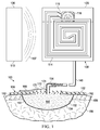
- the system 100 includes a reduced-pressure dressing 106 for disposing proximate to the tissue site 102; a wireless, reduced-pressure pump 108 fluidly coupled to the reduced-pressure dressing 106; and a base unit 110 having a RFID reader 112.
- the wireless, reduced-pressure pump 108 includes a first RFID antenna 114 and a micro-pump device 116.
- the RFID reader 112 is configured to provide and transmit a pump signal that provides power to the first RFID antenna 114.
- the pump signal received by the first RFID antenna 114 powers the micro-pump device 116.
- Remotely powering the micro-pump device 116 provides a number of potential benefits. The benefits may include ease of application.
- the wireless, reduced-pressure pump 108 may be a self-contained, disposable unit. It should be noted that some variation is shown between figures in order to show some of the potential variations in the illustrative system 100.
- the system 100 may be used with various different types of tissue sites 102.
- the tissue site 102 may be the bodily tissue of any human, animal, or other organism, including bone tissue, adipose tissue, muscle tissue, dermal tissue, vascular tissue, connective tissue, cartilage, tendons, ligaments, body cavity or any other tissue.
- Treatment of the tissue site 102 may include removal of fluids, e.g., exudate or ascites.
- the wireless, reduced-pressure pump 108 includes the first RFID antenna 114 that is coupled to a first processor 118 by electrical leads 119.
- the first processor 118 is coupled to the micro-pump device 116, or micro-pump, for receiving power.
- the first processor 118 may be incorporated into the micro-pump device 116.
- the first processor 118 and micro-pump device 116 may be located within a pump pouch 120.
- the pump pouch 120 may be formed by coupling a first pump-sealing member 122 to a second pump-sealing member 124.
- the pump pouch 120 may also be formed by other techniques such as casting the pump pouch 120 from a polymer.
- At least a portion of the pump pouch 120 comprises a fluid reservoir 126 for receiving and retaining fluids 127 from the tissue site 102.
- the micro-pump device 116 may be a piezoelectric pump, a peristaltic pump, or other small pump that produces reduced pressure with minimal power requirements.
- the first processor 118 is operable to receive a pressure message signal from a pressure sensing device 138. In response to receiving the pressure message signal, the first processor 118 produces a control signal to activate or deactivate the micro-pump device 116.
- the pressure sensing device 138 may be a transducer or may be a simple switch that is activated if sufficient reduced pressure is present.
- the base unit 110 includes a second processor 128 coupled to the RFID reader 112.
- a control panel 130 e.g., a user interface
- a first display 132 and a power source 134 e.g., a battery or electrical connection
- the base unit 110 may include a base housing 136.
- the second processor 128 and RFID reader 112 are configured to transmit a signal 137, e.g., a pump signal or a pressure inquiry signal, to the first RFID antenna 114.
- the first RFID antenna 114 of the reduced-pressure pump 108 is coupled by electrical leads 119 or a wireless coupling to the first processor 118.
- the first processor 118 is coupled to the micro-pump device 116 to provide power and control the micro-pump device 116.
- a first power source 140 may be included to provide additional power to the first processor 118.
- a pressure sensing device 138 may be coupled to the first processor 118.
- the pressure sensing device 138 is fluidly coupled to and senses pressure in a pressure sensing lumen 166 (or vent passageway 174 or interface distribution manifold 150).
- the micro-pump device 116 is fluidly coupled to a fluid reservoir 126.
- the fluid reservoir 126 receives and retains the fluids 127 from a reduced-pressure lumen 164 or from the interface distribution manifold 150.
- the pump signal transmitted by the base unit 110 is received by the first RFID antenna 114 and energizes the micro-pump device 116 to produce reduced pressure.
- the pressure inquiry signal is transmitted to the first processor 118 of the wireless, reduced-pressure pump 108 by the second processor 128 and RFID reader 112.
- the first processor 118 and pressure sensing device 138 of the wireless, reduced-pressure pump 108 transmit a pressure message signal indicative of the pressure experienced at the reduced-pressure dressing 106 to the base unit 110.
- the second processor 128 is configured to receive the pressure message signal from the wireless, reduced-pressure pump 108 and prepare a control signal.
- the second processor 128 and RFID reader 112 are configured to transmit the control signal to the wireless, reduced-pressure pump 108 to activate or deactivate the micro-pump device 116.
- the first processor 118 is operable to receive a pressure message signal from the pressure sensing device 138 and to produce a control signal to activate or deactivate the micro-pump device 116.
- the wireless, reduced-pressure pump 108 generates reduced pressure that is delivered to the tissue site 102.
- the wireless, reduced-pressure pump 108 receives and retains fluids from the tissue site 102.
- Reduced pressure generally refers to a pressure less than the ambient pressure at a tissue site that is being subjected to treatment. In most cases, this reduced pressure will be less than the atmospheric pressure at which the patient is located. Alternatively, the reduced pressure may be less than a hydrostatic pressure at the tissue site. Unless otherwise indicated, values of pressure stated herein are gauge pressures.
- the reduced pressure delivered may be constant or varied (patterned or random) and may be delivered continuously or intermittently. Consistent with the use herein, unless otherwise indicated, an increase in reduced pressure or vacuum pressure typically refers to a relative reduction in absolute pressure.
- the wireless, reduced-pressure pump 108 provides the reduced pressure for the system 100.
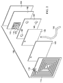
- the wireless, reduced-pressure pump 108 may include a first distribution manifold 142, a diverter layer 144, and an absorbent layer 146.
- a vent 176 is used to fluidly couple an exhaust from the micro-pump device 116 to an exterior of the wireless, reduced-pressure pump 108.
- the first distribution manifold 142 functions to distribute reduced pressure generated by the micro-pump device 116.
- An air/liquid separator 143 e.g., a hydrophobic filter, may be placed between the micro-pump device 116 and the first distribution manifold 142 to prevent liquid from entering the micro-pump device 116.
- the absorbent layer 146 functions to receive and retain fluids from the tissue site 102.
- the absorbent layer 146 may be made from any material capable of absorbing liquid, such as exudate from the tissue site 102.
- the absorbent layer 146 may be made from super absorbent fibers.
- the super absorbent fibers may retain or bond to the liquid in conjunction with a physical or chemical change to the fibers.
- the super absorbent fiber may include the Super Absorbent Fiber (SAF) material from Technical Absorbents, Ltd. of Grimsby, United Kingdom.
- SAF Super Absorbent Fiber
- the absorbent layer 146 may be a sheet or mat of fibrous material in which the fibers absorb liquid from the tissue site 102.
- the structure of the absorbent layer 146 that contains the fibers may be either woven or non-woven.
- the fibers in the absorbent layer 146 may gel upon contact with the liquid, thereby trapping the liquid.
- Spaces or voids between the fibers may allow reduced pressure that is applied to the absorbent layer 146 to be transferred within and through the absorbent layer 146.
- the fiber density of the fibers in the absorbent layer 146 may be approximately 1.4 grams per millimeter.
- the diverter layer 144 is disposed adjacent to the absorbent layer 146 and the first distribution manifold 142.
- the diverter layer 144 is formed from a liquid impermeable material but contains a plurality of apertures 145.
- the plurality of apertures 145 allow reduced pressure from the micro-pump device 116 to be transmitted through the diverter layer 144 at desired locations.
- the diverter layer 144 helps control the pattern of reduced pressure as applied to the absorbent layer 146.
- the reduced pressure is distributed to the diverter layer 144 by the first distribution manifold 142.
- the apertures 145 may be arranged in a pattern for applying the reduced pressure to portions of the absorbent layer 146 to enhance the capability of the absorbent layer 146 to continue transferring reduced pressure to the tissue site 102 as the absorbent layer 146 absorbs more fluid from the tissue site 102.
- the plurality of apertures 145 may be positioned in a pattern around a peripheral portion of the diverter layer 144 away from the center of the diverter layer 144 such that the reduced pressure is applied to the absorbent layer 146 away from a center region of the absorbent layer 146.
- the diverter layer 144 acts in conjunction with the first distribution manifold 142 to ensure that the absorption capabilities and absorption efficiency of the absorbent layer 146 are increased relative to an absorbent layer 146 that is not used in conjunction with a diverter layer 144. By providing better distribution of liquid throughout the absorbent layer 146, the diverter layer 144 also increases the effective capacity and treatment time of the wireless, reduced-pressure pump 108.
- the diverter layer 144 may be made from any material that enhances the reduced pressure transmission and storage capabilities of an adjacent absorbent layer.
- the diverter layer 144 may be made from a material that is substantially impermeable to liquid and gas and that diverts the reduced pressure to pass through apertures 145.
- the material from which the diverter layer 144 is made may have a predetermined moisture vapor transfer rate that is consistent with gas permeability.
- the diverter layer 144 may still include a pattern of apertures for transmitting a greater volume of liquid or gas than that permitted by a gas-permeable material not having apertures. It should be noted, however, that permeability of the diverter layer 144 to gas but not liquid may result in increased transmission of reduced pressure through the dressing while still directing liquid flow around or near the perimeter of the diverter layer 144.
- the first distribution manifold 142, the diverter layer 144, and the absorbent layer 146 may be disposed within the pump pouch 120.
- the wireless, reduced-pressure pump 108 may also include the pressure sensing device 138, which is fluidly coupled to the reduced-pressure dressing 106 and in communication with the first processor 118 for sensing pressure.
- the reduced-pressure conduit 148 delivers fluids from the reduced-pressure dressing 106 to the wireless, reduced-pressure pump 108.
- the reduced-pressure conduit 148 is disposed directly into the absorbent layer 146.
- an interface (not shown) fluidly couples the reduced-pressure conduit 148 and the absorbent layer 146.
- the reduced-pressure dressing 106 is disposed against the tissue site 102.
- the tissue site 102 may be, for example, the wound 104 through epidermis 156 and into subcutaneous tissue 158 or any other tissue site.
- the reduced-pressure dressing 106 may be any device for providing reduced pressure to the tissue site 102 and for receiving fluids from the tissue site 102.
- the reduced-pressure dressing 106 may be formed with a foam member, a structure with a plurality of defined channels, a suction tube, or other device.
- the reduced-pressure dressing 106 may include the interface distribution manifold 150 for placing proximate to the tissue site 102, a dressing sealing member 152, and a reduced-pressure interface 154.
- a manifold is a substance or structure that is provided to assist in applying reduced pressure to, delivering fluids to, or removing fluids from a tissue site 102.
- the interface distribution manifold 150 typically includes a plurality of flow channels or pathways that distribute fluids provided to and removed from the tissue site 102 around the interface distribution manifold 150.
- the flow channels or pathways are interconnected to improve distribution of fluids provided or removed from the tissue site 102.
- the interface distribution manifold 150 may be a biocompatible material that is capable of being placed in contact with the tissue site 102 and distributing reduced pressure to the tissue site 102.
- interface distribution manifolds may include without limitation the following: devices that have structural elements arranged to form flow channels, e.g., cellular foam, open-cell foam, porous tissue collections, liquids, gels, and foams that include, or cure to include, flow channels; foam; gauze; felted mat; or any other material suited to a particular biological application.
- devices that have structural elements arranged to form flow channels e.g., cellular foam, open-cell foam, porous tissue collections, liquids, gels, and foams that include, or cure to include, flow channels
- foam gauze; felted mat; or any other material suited to a particular biological application.
- the interface distribution manifold 150 is a porous foam and includes a plurality of interconnected cells or pores that act as flow channels.
- the porous foam may be a polyurethane, open-cell, reticulated foam such as GranuFoam® material available from Kinetic Concepts, Incorporated of San Antonio, Texas.
- the interface distribution manifold 150 may also be used to distribute fluids such as medications, antibacterials, growth factors, and various solutions to the tissue site 102.
- Other layers may be included in or on the interface distribution manifold 150, such as absorptive materials, wicking materials, hydrophobic materials, and hydrophilic materials.
- the interface distribution manifold 150 in whole or in part may be constructed from bioresorbable materials that may remain in a patient's body following use of the reduced-pressure dressing 106.
- Suitable bioresorbable materials may include, without limitation, a polymeric blend of polylactic acid (PLA) and polyglycolic acid (PGA).
- the polymeric blend may also include without limitation polycarbonates, polyfumarates, and capralactones.
- the interface distribution manifold 150 may further serve as a scaffold for new cell-growth, or a scaffold material may be used in conjunction with the interface distribution manifold 150 to promote cell-growth.
- a scaffold is a substance or structure used to enhance or promote the growth of cells or formation of tissue, such as a three-dimensional porous structure that provides a template for cell growth.
- Illustrative examples of scaffold materials include calcium phosphate, collagen, PLA/PGA, coral hydroxy apatites, carbonates, or processed allograft materials.
- the interface distribution manifold 150 is covered by a dressing sealing member 152.
- the dressing sealing member 152 may be any material that provides a fluid seal.
- a fluid seal is a seal adequate to maintain reduced pressure at a desired site given the particular reduced-pressure source or subsystem involved.
- the dressing sealing member 152 may, for example, be an impermeable or semi-permeable, elastomeric material.
- Elastomeric materials have the properties of an elastomer. It generally refers to a polymeric material that has rubber-like properties. More specifically, most elastomers have ultimate elongations greater than 100% and a significant amount of resilience. The resilience of a material refers to the material's ability to recover from an elastic deformation.
- elastomers include, but are not limited to, natural rubbers, polyisoprene, styrene butadiene rubber, chloroprene rubber, polybutadiene, nitrile rubber, butyl rubber, ethylene propylene rubber, ethylene propylene diene monomer, chlorosulfonated polyethylene, polysulfide rubber, polyurethane (PU), EVA film, co-polyester, and silicones.
- Additional, specific examples of dressing sealing member materials include a silicone drape, 3M Tegaderm® drape, polyurethane (PU) drape such as one available from Avery Dennison Corporation of Pasadena, California.
- the dressing sealing member 152 forms a sealed space 160 over the tissue site 102, which may or may contain the micro-pump device 116.
- An attachment device 162 may be used to retain the dressing sealing member 152 against the patient's epidermis 156 or another layer, such as a gasket or additional sealing member.
- the attachment device 162 may take numerous forms.
- the attachment device 162 may be a medically acceptable, pressure-sensitive adhesive that extends about a periphery or all of the dressing sealing member 152 or covers at least a potion of the dressing sealing member 152 on a patient-facing side over the epidermis 156.
- the reduced-pressure interface 154 may be used to provide fluid communication between the reduced-pressure conduit 148 and the sealed space 160 of the reduced-pressure dressing 106.
- the reduced pressure may be delivered through the reduced-pressure conduit 148 to the reduced-pressure interface 154 and then to the sealed space 160.
- the reduced-pressure interface 154 is a T.R.A.C. ® Pad or Sensa T.R.A.C. ® Pad available from KCI of San Antonio, Texas.
- the reduced-pressure conduit 148 may include the reduced-pressure lumen 164 and the pressure sensing lumen 166 formed as an integral conduit as shown in FIGURE 1 or separately as shown in FIGURE 3 .
- pressure sensing capability may be added to the reduced-pressure dressing 106 to function in addition to or in lieu of pressure sensing device 138.
- the reduced-pressure dressing 106 may include a second RFID antenna 168, a third processor 170, and a second pressure sensing device 172.
- the third processor 170 is coupled to the second RFID antenna 168 and to the second pressure sensing device 172.
- a vent passageway 174 provides fluid communication between the sealed space 160 and the second pressure sensing device 172.
- the third processor 170 and the second pressure sensing device 172 are operable to receive a pressure inquiry signal from the base unit 110 and respond with a pressure message signal indicative of the pressure in the sealed space 160.
- the wireless, reduced-pressure pump 108 is a wireless and passive (i.e., no battery) device. As such, the wireless, reduced-pressure pump 108 has no source of power other than power delivered through the first RFID antenna 114. In some embodiments, the wireless, reduced-pressure pump 108 may contain a capacitor for storing electrical energy. In another illustrative embodiment, the first power source 140 as shown in FIGURE 3 may be provided to augment the power delivered through the first RFID antenna 114 or to operate the micro-pump device 116. The first power source 140 may be recharged by power from the first RFID antenna 114.
- the micro-pump device 116 may take numerous forms such as a piezoelectric pump, peristaltic pump, or other miniaturized pump. Referring now primarily to FIGURE 5 , an illustrative embodiment of a micro-pump device 116 that is suitable for use as an aspect of the wireless, reduced-pressure pump 108 is presented.
- the micro-pump device 116 includes a cavity 178 that is defined by a first end wall 180, a second end wall 182, and an annular side wall 184.
- the cavity 178 may be substantially circular in shape, but other shapes are possible, such as elliptical. In one illustrative embodiment, the cavity 178 may hold about 10 ml of fluid or may hold more or less.
- the cavity 178 is provided with a nodal inlet 186, which may be valved or unvalved.
- the cavity 178 may also have a valved outlet 190.
- the first end wall 180 may be a disc 192.
- an actuator 194 such as a piezoelectric disc, magnetostrictive device, or solenoid actuated device.
- the actuator 194 is electrically coupled to a drive circuit, which is controlled by the processor.
- the drive circuit will apply an alternating electrical signal to the actuator 194 to induce an oscillation in the disc 192.
- the frequency of the oscillation can be adjusted to match the natural frequency of the chamber.
- the piezoelectric disc may be less than 1 mm in thickness and may be tuned to operate at more than 500 Hz, more than 10 kHz, or even higher than 20 kHz.
- the actuator 194 may vibrate in a direction substantially perpendicular to the plane of the cavity 178 as shown, thereby generating radial pressure oscillations within the fluid in the cavity 178.
- One or more micro-pump devices 116 may be used in parallel or series.
- the micro-pump device 116 has a fluid in the cavity 178 and has a substantially cylindrical shape that is bounded by the first end wall 180, second end wall 182, and side wall 184. At least two apertures, e.g., inlet 186 and outlet 190, are formed through the walls 180, 182, 184 forming the cavity 178.
- the cavity 178 has a radius, r, and a height, h, and r/h > 1.2 and h 2 /r > 4 x 10 -10 m.
- the actuator 194 which is a piezoelectric disc, creates an oscillatory motion of one of the end walls 180, 182 in a direction that is substantially perpendicular to the plane of the first end wall 180 and second end wall 182. Axial oscillations of the end walls 180, 182 drive radial oscillations of fluid pressure in the cavity 178 and allow for pumping that creates reduced pressure.
- the micro-pump device 116 is like an acoustic pump in that an acoustic resonance is set up within the cavity 178.
- the inlet 186 is used to pull fluids, and the outlet 190 is coupled to a vent, e.g., the vent 176 in FIGURE 4 , to discharge to an exterior. Other micro-pump devices may be used.
- the micro-pump device 116 may be the type of micro-pump shown in United States Patent Publication 2009/0240185 (application 12/398,904; filed 5 March 2009 ), entitled, "Dressing and Method for Applying Reduced Pressure To and Collecting And Storing Fluid from a Tissue Site,” which is incorporated herein for all purposes.
- the reduced-pressure dressing 106 is applied to the tissue site 102.
- the interface distribution manifold 150 is disposed proximate to the tissue site 102.
- the interface distribution manifold 150 and the tissue site 102 are covered by the dressing sealing member 152 to create the sealed space 160.
- the attachment device 162 on the patient-facing side of the dressing sealing member 152 may help provide a fluid seal against a portion of the patient's epidermis 156.
- the reduced-pressure interface 154 may be applied, such as for example by cutting a small aperture in the dressing sealing member 152 and securing the reduced-pressure interface 154 over or through the aperture, or hole.
- the wireless, reduced-pressure pump 108 is then provided and fluidly coupled by the reduced-pressure conduit 148 to the reduced-pressure interface 154.
- the wireless, reduced-pressure pump 108 is positioned such that the first RFID antenna 114 is placed within operating range of the base unit 110.
- the first RFID antenna 114 is placed within a few millimeters of the RFID reader 112 of the base unit 110.
- the first RFID antenna 114 may be placed as far away as ten meters from the RFID reader 112. Any distance within the given range may be readily used.
- the base unit 110 is then activated by the user.
- the base unit 110 transmits a pump signal 137 to the wireless, reduced-pressure pump 108.
- the pump signal is received by the first RFID antenna 114, and the energy of the pump signal is delivered to the first processor 118.
- the first processor 118 provides energy to the micro-pump device 116.
- the micro-pump 116 creates reduced pressure that is delivered into the fluid reservoir 126 that is fluidly coupled to the reduced-pressure conduit 148.
- the reduced pressure is delivered to the reduced-pressure dressing 106 through the reduced-pressure conduit 148. Fluids from the tissue site 102 flow through the interface distribution manifold 150, reduced-pressure interface 154, and reduced-pressure conduit 148 into the fluid reservoir 126.
- the pressure at the tissue site 102 may be monitored directly or indirectly using a pressure sensing device, such as pressure sensing device 138 of FIGURE 3 or second pressure sensing device 172 of FIGURE 1 .
- a pressure sensing device such as pressure sensing device 138 of FIGURE 3 or second pressure sensing device 172 of FIGURE 1 .
- the second processor 128 and the RFID reader 112 of the base unit 110 may, separate from the pump signal or with the pump signal, transmit a pressure inquiry signal to the wireless, reduced-pressure pump 108.
- the first processor 118 and pressure sensing device 138 may prepare a pressure message signal to communicate a measurement of the pressure at the tissue site. Then, the pressure message signal may be used for further processing by the first processor 118 to develop a pump control signal for activating or deactivating the micro-pump 116 as may be needed.
- the first processor 118 may transmit the pressure message signal via the first RFID antenna 114 to the RFID reader 112. After arriving at the RFID reader 112, the pressure message signal is delivered to the second processor 128. Using the pressure message signal, the second processor 128 may prepare a pump control signal that is transmitted by the RFID reader 112 to the wireless, reduced-pressure pump 108 to deactivate or activate the micro-pump 116 as needed.
- an alarm signal is created by the base unit 110 or by the wireless, reduced-pressure pump 108.
- the alarm may be a separate audible device, visual alarm, or the micro-pump 116 may function at a different frequency range, e.g., lower, to make an audible noise for the alarm.
- the reduced-pressure dressing 106 includes the second RFID antenna 168 that is coupled to the third processor 170, which is coupled to the second pressure sensing device 172.
- the second pressure sensing device 172 experiences the pressure within the sealed space 160 via the vent passageway 174.
- the base unit 110 transmits a pressure inquiry signal to the second RFID antenna 168.
- the second pressure sensing device 172 and third processor 170 produce a pressure message signal that is transmitted by the second RFID antenna 168 to the base unit 110.
- the base unit 110 then produces a pump control signal that is transmitted to the wireless, reduced-pressure pump 108 to activate or deactivate the micro-pump 116.
- the third processor 170 may evaluate the pressure and prepare a pump control signal as part of a feedback or control loop.
- the wireless, reduced-pressure pump 108 may be a self-contained, disposable pouch design that may be removably secured to a base unit 110 on a pole 196.
- a pump pouch 120 is formed with a first pump-sealing member 122 and a second pump-sealing member 124.
- the perimeter of the pump pouch 120 may include a first flange 123 and a second flange 125.
- the pump pouch 120 may be divided or partitioned into numerous compartments if desired. For example, a compartment (not explicitly shown) may be formed that has the micro-pump 116 within the compartment and another compartment may formed that contains the absorbent layer 146.
- the flanges 123, 125 on the illustrative embodiment of the pump pouch 120 may be formed by welding, bonding or otherwise attaching portions of the first pump-sealing member 122 and second pump-sealing member 124.
- the first flange 123 may include one or more apertures 129 for receiving one or more posts 198.
- the posts 198 secure the pump pouch 120 adjacent to the base unit 110.
- the reduced-pressure conduit 148 may enter through an aperture 149 in the second flange 125 that provides a sealed, interference fit or has a coupling that provides a sealed connection. Other connections may be used.
- the first RFID antenna 114 may be placed closest to the base unit 110 such that the first RFID antenna 114 is immediately adjacent to RFID reader 112 of the base unit 110 as shown best in FIGURE 4 .
- the first RFID antenna 114 is positioned two millimeters or one millimeter (1 mm) or less from the RFID reader 112.
- the RFID reader 112 and the first RFID antenna 114 may be substantially matched and aligned.
- the wireless, reduced-pressure pump 108 may be attached to a post 198 with the first RFID antenna 114 facing outward towards a remotely located base unit 110 as suggested in FIGURE 1 .
- the base unit 110 may be located at a central hub area where the wireless, reduced-pressure pump 108 is monitored and powered using the base unit 110, which may be as far away as ten meters or more.
- the base unit 110 may include the control panel 130 and one or more displays 132.
- the base unit 110 may include a base housing or base body 136.
- the base housing or body 136 may include a shelf portion 199 that may provide physical support to a portion of the wireless, reduced-pressure pump 108 when the wireless, reduced-pressure pump 108 fills with fluids from the tissue site 102.
- the wireless, reduced-pressure pump 108 shown in FIGURE 6 is shown before use. With the embodiments of FIGURES 4 and 6 , when the wireless, reduced-pressure pump 108 has reached its capacity for holding fluids, the micro-pump 116 may be deactivated and the user may dispose of the entire wireless, reduced-pressure pump 108.
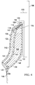
- the wireless, reduced-pressure pump 200 may be used as part of a system for treating a tissue site, e.g., the system of FIGURE 1 .
- the wireless, reduced-pressure pump 200 includes a plurality of wall members 202 that form a first chamber 204 and a second chamber 206.
- One of the plurality of wall members 202 is a partitioning wall 208 that separates the first chamber 204 from the second chamber 206.
- a micro-pump 210 which is analogous to the micro-pump 116 of the previous figures, may be disposed within the first chamber 204.
- the micro-pump 116 is configured such that the inlet 212 that receives fluid (or said another way, discharges reduced pressure) is fluidly coupled to the second chamber 206.
- the micro-pump 210 has an outlet or vent 214 that is fluidly coupled to the first chamber 204.
- the micro-pump 210 vents positive pressure through outlet or vent 214 into the first chamber 204.
- a portion of one of the plurality of wall members 202 that forms the first chamber 204 contains an aperture 216.
- An optional relief valve 218 is coupled to the aperture 216.
- the relief valve 218 is configured to allow pressure within the first chamber 204 to vent to an exterior of the wireless, reduced-pressure pump 200 when the pressure exceeds a first threshold pressure.
- At least a portion of the plurality of wall members 202 that make up the second chamber 206 includes an inflatable support member and typically a plurality of inflatable support members 220. While a plurality of inflatable support members 220 are presented, it should be understood that a single inflatable support member may be used create the second chamber 206.
- the inflatable support members 220 are in fluid communication with the first chamber 204, such as through a plurality of apertures 222. Thus, the positive pressure within the first chamber 204 fills the plurality of inflatable support members 220. As the plurality of inflatable support members 220 are filled with sufficient fluid, the plurality of inflatable support members 220 gain relative rigidity that provides a structure that helps provide volume to the second chamber 206. Fluids 223 from a tissue site are received through a reduced-pressure conduit 224 into the volume of the second chamber 206.
- the wireless, reduced-pressure pump 200 which is shown in the shape of a pyramid, may be formed to take other shapes, e.g., a box, a cylinder, or any other shape.
- the micro-pump 210 may be fully or partially powered by a pump signal delivered to a RFID antenna 226.
- the RFID antenna 226 is coupled to a first processor 228.
- the first processor 228 is electrically coupled to the micro-pump 210 by an electrical lead 230, which may be contained in one of the plurality of wall members 202 but is shown separately in FIGURE 7 .
- a floor portion 232 of the plurality of wall members 202 may be contained within a platform member 234.
- the reduced-pressure conduit 224 is coupled to a reduced-pressure dressing, such as reduced-pressure dressing 106 of FIGURES 1 and 3 .
- a base unit e.g., base unit 110 of FIGURE 1 , is used to transmit a pump signal or a pump activation signal to the RFID antenna 226 of the wireless, reduced-pressure pump 200.
- the pump signal received by the RFID antenna 226 is delivered to the first processor 228.
- Power is delivered from the first processor 228 to the micro-pump 210 to energize micro-pump 210.
- reduced pressure is delivered into the second chamber 206 and positive pressure is delivered to the first chamber 204.
- a spacer member may cover the inlet 212 to avoid a vapor lock during start up before the inflatable support members 220 fill.
- the maximum volume is achieved for the second chamber 206. Meanwhile, the reduced pressure in the second chamber 206 is delivered to the reduced-pressure conduit 224. Fluids 223 (including liquids) are introduced into the second chamber 206.
- a reduced-pressure sensing device e.g., analogous to pressure sensing device 138 in FIGURE 3
- a reduced-pressure sensing device may be included in the reduced-pressure pump 200.
- the reduced-pressure conduit 224 may also have a pressure sensing lumen that is fluidly coupled to the reduced-pressure sensing device for measuring pressure at a distribution manifold. In both examples, the pressure sensing device is coupled to the first processor 228 to develop a pressure message signal.
- the pressure message signal may be supplied in response to a pressure inquiry signal from a base unit or self-generated by the first processor 228.
- the first processor 228 may use the pressure message signal to develop a pump control signal that is delivered to the micro-pump 210.
- the pressure message signal may be transmitted to the base unit where a processor in the base unit may develop a pump control signal similar to the embodiments previously presented.
- the wireless, reduced-pressure pumps 108, 200 previously presented have, instead of having RFID antennas, electrical leads or sockets and plugs between the pumps and base.
- the electrical leads or sockets and plugs may readily plug into one another for communicating power and signals.
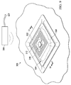
- the reduced-pressure system 300 includes a wireless, reduced-pressure dressing 304 and a base unit 306.
- the base unit 306 may include a power connector 307.
- the wireless, reduced-pressure dressing 304 is a self-contained, disposable dressing that receives power and control from the base unit 306.
- the base unit 306 may be substantially adjacent to the wireless, reduced-pressure dressing 304, e.g., within one or two millimeters, or up to 10 meters or more away or anywhere in between.
- the micro-pump 316 may be separate from an absorbent layer or absorbent member 310, such that after use, the micro-pump 316 may be readily separated. The micro-pump 316 may then be reconditioned and reused.
- the wireless, reduced-pressure dressing 304 includes an interface distribution manifold 308 that is placed proximate to the tissue site 302.
- the wireless, reduced-pressure dressing 304 may also include an absorbent layer 310, a RFID antenna 312, and a first processor 314.
- the RFID antenna 312 is electrically coupled to the first processor 314.
- the first processor 314 is electrically coupled to the micro-pump 316.
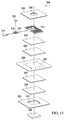
- the interface distribution manifold 308, absorbent layer 310, RFID antenna 312, first processor 314, and micro-pump 316 may all be retained in place and secured in a sealed space 318 by one or more sealing members, such as sealing member 320. Additional layers and components may be included in the wireless, reduced-pressure dressing 304.
- FIGURES 9-11 includes additional layers and components.
- the additional layers and components may be arranged in different orders.
- a sealing layer 322 is used to seal the wireless, reduced-pressure dressing 304 around the tissue site 302.
- the sealing layer 322 is formed with an aperture 323 for providing fluid communication to the interface distribution manifold 308.
- a first internal distribution manifold 324 is positioned in fluid communication with the interface distribution manifold 308 and the tissue site 302.
- the absorbent layer 310 is positioned in fluid communication with the first internal distribution manifold 324, the interface distribution manifold 308, and a tissue site 302.
- a diverter layer 326 is positioned adjacent to the absorbent layer 310.
- a second internal distribution manifold 328 is positioned in fluid communication with the diverter layer 326.
- the diverter layer 326 is formed with a plurality of apertures 327 that may take numerous patterns and forms.
- the diverter layer 326 is shown in this particular illustrative embodiment with a plurality of apertures 327 forming a square pattern.
- the square pattern has corner apertures that are larger than the other apertures.
- a liquid-air separator 330 is positioned adjacent to the second internal distribution manifold 328.
- the micro-pump 316, RFID antenna 312, and first processor 314 may be adjacent to the liquid-air separator 330.
- a charcoal filter 332 or other odor relieving device may be positioned over an outlet 334 of the micro-pump 316.
- the sealing member 320 is formed with an aperture 336 that allows the outlet 334 of the micro-pump 316 to exhaust to an exterior of the wireless, reduced-pressure dressing 304.
- the outlet 334 and aperture 336 together form a vent 338.
- the micro-pump 316 may be a micro-pump that is small and light enough such that the integrated wireless, reduced-pressure dressing 304 is able to be maintained on the tissue site 302. Furthermore, the size and weight of the micro-pump 316 may be such that the integrated reduced-pressure dressing 304 does not pull or otherwise adversely affect the tissue site 302.
- the micro-pump 316 may be a disk pump having a piezoelectric actuator similar to that previously described. Reference is also made to the pumps shown in United States Patent Publication 2009/0087323 and United States Patent Publication 2009/0240185 , which are hereby incorporated by reference for all purposes.
- the micro-pump 316 may be a peristaltic pump that is used for pumping a variety of fluids. It should be understood that alternative pump technologies may be utilized and that rotary, linear, or other configurations of pumps may be utilized.
- the micro-pump 316 creates sufficient reduced pressure to be therapeutic for wound therapy.
- the micro-pump 316 has sufficient flow, reduced pressure, and operation life characteristics to enable continuous application of reduced pressure treatment.
- the flow may range between about 5-1000 ml/min and the reduced pressure may range between about -50 and -200 mm Hg (-6.6 to -26.6 kPa). It should be understood that alternative ranges may be utilized depending on the configuration of the integrated, wireless, reduced-pressure dressing 304, size of wound, or type of wound.
- multiple pumps may be positioned in a single dressing to deliver increased flow rates or vacuum levels as required.
- the micro-pump 316 is disposed within the dressing to avoid conduits and external canisters for collection of wound exudate.
- the micro-pump 316 includes the outlet 334 to release air or exhaust out of the reduced-pressure dressing 304. If the outlet 334 is used, the outlet 334 is in fluid communication with, or may be positioned within, the aperture 336 of the sealing member 320. Alternatively, the sealing member 320 may be sealed around an outlet port of the micro-pump 316 such that gas from the micro-pump 316 is able to exhaust directly through the aperture 336.
- the outlet 334 of the micro-pump 316 is oriented in a direction away from the liquid-air separator 330 (or hydrophobic filter) to avoid adding air to the wireless, reduced-pressure dressing 304.
- the air exhausts through an aperture 336 in the sealing member 320, which may include a one-way valve. Alternatively, the air or another gas could be exhausted through a gas-permeable portion of the sealing member 320 as long as the ability of the sealing member 320 to maintain reduced pressure is not affected.
- the piezoelectric actuator associated with the micro-pump 316 may be driven at different frequencies to act as a buzzer or vibrating alert system at times.
- the alert system may alert a user to an alarm condition.
- the alarm condition may indicate the presence of a leak in the dressing, a change in reduced pressure as measured by a sensor, that the dressing has absorbed a maximum capacity of liquid as may be indicated by an indicator, or that one or more layers are no longer manifolding reduced pressure efficiently.
- Control electronics may be physically or functionally incorporated as part of the first processor 314.
- the control electronics may be utilized to control operation of the micro-pump 316.
- the control electronics may be analog or digital and be configured with a regulator to regulate speed or duty cycle at which the micro-pump 316 operates.
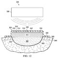
- the control electronics may be configured with a controller that receives sense signals from sensors or switches, e.g., a pressure sensing device (see 340 in FIG. 12 ).
- the sensors may be disposed throughout the wireless, reduced-pressure dressing 304 to sense parameters, such as pressure, temperature, moisture, chemistry, odor, or any other parameter that may be utilized in managing and controlling the micro-pump 316.
- the control electronics may include a computer processor or programmable gate array or other control device. It should be understood that the control electronics may include any form of digital or analog components to perform the functions described herein.
- the control electronics may be or include the first processor 314.
- the control electronics may be arranged to monitor and provide an alarm for certain conditions, e.g., (i) low pressure, (ii) excessive leak, (iii) level of absorbent layer, and (iv) battery state (if included).
- the control electronics may include electronics that monitor each of the parameters and generate an alarm signal (e.g., high-pitched beep, vibration, or light) using a speaker, vibrator, or illumination device, such as a light emitting diode (LED).
- an alarm signal e.g., high-pitched beep, vibration, or light
- the control electronics may notify a medical professional, patient, or family member that a parameter is outside of a desired range. For example, if a pressure at the tissue site 302 is below a therapeutic level, a continuous tone may be generated.
- the RFID antenna 312 is utilized to provide electric power to the micro-pump 316 and control electronics.
- a battery 342 may also be used to provide stored energy to augment power from the RFID antenna 312.
- the battery 342 may be any size and shape and may be of any material, such as polymer.
- the battery 342 may provide the entire needed power or a portion thereof.
- the battery 342 may be recharged by power from the RFID antenna 312.
- the battery 342 may be configured with a voltage level sensor that is monitored by the control electronics, and the control electronics may provide an alarm when a low power level is detected.
- the battery 342 may be directly connected to the micro-pump 316.
- the battery 342 may be connected to the control electronics or processor(s) that use power from the battery 342 to drive the micro-pump 316.
- the control electronics may provide continuous, modulated power, such as a pulsewidth modulated (PWM) signal, to drive the micro-pump 316.
- PWM pulsewidth modulated
- the sealing layer 322 is adhered to or otherwise connected to the sealing member 320 that is used to drape or otherwise cover the components of the reduced-pressure dressing 304.
- the sealing layer 322 may include a medical-grade adhesive material or other sealing device that is strong enough to form a vacuum seal with epidermis around a wound of a patient.
- the sealing layer 322 may be a band that has an aperture 323 that is slightly larger than the geometric parameters of the liquid-air separator 330 or other layer so that the sealing member 320 contacts epidermis around the tissue site 302 of the patient.
- the sealing member 320 is impermeable to fluids, such as air and liquids.
- the sealing member 320 may be adhered to the diverter layer 326 and the diverter layer 326 adhered to the sealing member 320 to create an upper dressing portion and a lower dressing portion.
- the upper dressing portion may include the sealing member 320, the micro-pump 316 and related components, the liquid-air separator 330, the second internal distribution manifold 328, and the diverter layer 326.
- the lower dressing portion may include the absorbent layer 310, the first internal distribution manifold 324, the sealing layer 322, and the interface distribution manifold 308.
- the wireless, reduced-pressure dressing 304 may be configured to allow replacement of the lower dressing portion once the wireless, reduced-pressure dressing has absorbed a maximum capacity of fluid.
- the upper dressing portion may be reused after the lower dressing portion is replaced. This allows multiple uses of the micro-pump 316, while disposable portions of the dressing may be replaced.
- the micro-pump 316, first processor 314, and RFID antenna 312 may be removed from the dressing for reuse and the remaining layers of the dressing replaced.
- only the absorbent layer 310 may be replaced.
- only the absorbent layer 310 and the interface distribution manifold 308 may be replaced.
- the charcoal filter 332 may be utilized in the wireless, reduced-pressure dressing 304 to reduce odors created by the tissue site 302 and dispersed from the wireless, reduced-pressure dressing 304.
- the charcoal filter 332 may be disposed above a valve or other output vent from the micro-pump 316 to filter exhaust from the micro-pump 316 prior to being released from the integrated reduced-pressure dressing 304. It should be understood that the charcoal filter 332 may be alternatively configured and disposed above or below the micro-pump 316. In another illustrative embodiment, rather than using a charcoal filter, charcoal may be integrated into any or all of the different layers utilized in the integrated reduced-pressure dressing 304.
- the reduced-pressure system 300 of FIGURES 9-11 is applied by placing the interface distribution manifold 308 proximate to the tissue site 302. Placing the sealing layer 322 over the interface distribution manifold 308 such that the aperture 323 is over the interface distribution manifold 308.
- the first internal distribution manifold 324 is placed adjacent to the first interface distribution manifold 308 and possibly a portion of the sealing layer 322.
- the absorbent layer 310 is placed adjacent to the first internal distribution manifold 324.
- the diverter layer 326 may be placed over all the components thus presented.
- the second internal distribution manifold 328 may be placed adjacent to a portion of the diverter layer 326 along with the liquid-air separator 330.
- the micro-pump 316, RFID antenna 312, and first processor 314 may be applied.
- the components mentioned here may also be pre-assembled as a dressing stack.
- the sealing member 320 is used to create a seal that forms a sealed space 318.
- the base unit 306 is used to transmit a pump signal as before to the RFID antenna 312 that is received by the first processor 314 and is used to provide power to the micro-pump 316.
- the first processor 314 may further include one or more capacitors for holding power or one or more batteries such as a rechargeable battery.
- the pump signal causes reduced pressure to be developed by the micro-pump 316.
- the reduced pressure is transmitted to the tissue site 302 to remove fluids or to provide reduced pressure therapy.
- the fluids removed from the tissue site 302 are transmitted within the reduced-pressure dressing 304 to the absorbent layer 310 where the fluids are retained or substantially retained.
- a pressure sensing device may be included as part of the wireless, reduced-pressure dressing 304 to provide a pressure message signal to the base unit 306.
- the reduced-pressure system 300 includes a wireless, reduced-pressure dressing 304 and a base unit 306.
- the reduced-pressure system 300 in FIGURE 12 is analogous to the system presented in FIGURES 9-11 , except that the wireless, reduced-pressure dressing 304 includes fewer components and includes the addition of a pressure sensing device 340 that is electrically coupled to the first processor 314.
- an optional battery 342 is included.
- the battery 342 may supplement power provided through the RFID antenna 312 or may be used as the primary power source and then recharged by the RFID antenna 312.
- the RFID antenna 312 receives power from the base unit 306.
- the sealing member 320 is shown secured to the epidermis 344 by an attachment device 346. Components included in the previous dressing of FIGURES 9-11 have been assigned the same reference numerals and are not necessarily discussed further here.
- the reduced-pressure system 300 of FIGURE 12 may be used by first applying the interface distribution manifold 308 adjacent to the tissue site 302.
- the absorbent layer 310 is placed in fluid communication with the interface distribution manifold 308.
- the liquid-air separator 330 may be placed over the absorbent layer 310.
- the RFID antenna 312, pressure sensing device 340, first processor 314, micro-pump 316, and battery 342 are disposed on the liquid-air separator 330.
- only some of the components, such as the micro-pump 316 may be adjacent to the liquid-air separator 330.
- the sealing member 320 is applied over the tissue site 302 to create a sealed space 318 and to cover all the aforementioned components.
- the previously mentioned components may be entirely or partially preassembled.
- the base unit 306 transmits a pump signal or pump activation signal to the reduced-pressure dressing 304 that activates the micro-pump 316.
- the micro-pump 316 removes air or other fluids from the sealed space 318 and thereby initiates treatment of the tissue site 302 with reduced pressure.
- the base unit 306 may also transmit a pressure inquiry signal.
- the RFID antenna 312, the first processor 314, and the pressure sensing device 340 develop a pressure message signal that is transmitted by the RFID antenna to the RFID reader (not explicitly shown) of the base unit 306.
- the base unit 306 may include a processor (not explicitly shown) that receives the pressure message signal and develops a pump control signal to activate or deactivate the micro-pump 316. If the reduced pressure is in the desired therapy range, the micro-pump 316 may be deactivated.
- the base unit 306 may transmit a pump signal that activates or continues the micro-pump 316 to produce more reduced pressure. If more than a sufficient elapsed time has passed without the desired pressure being reached, an alarm may be triggered by the base unit 306.
- the wireless, reduced-pressure dressing 304 may include a galvanic cell (not explicitly shown) to provide a full indication message signal when exudate or other body fluids electrically couple two electrodes. The full indication message signal would be transmitted with the RFID antenna 312 to the base unit 306 indicating that the dressing is full.
- FIGURE 13 another illustrative embodiment of a reduced-pressure dressing 400 is presented that includes a wireless, reduced-pressure pump 430.
- the reduced-pressure dressing 400 is shown in an exploded view over a tissue site 402, such as a wound, on a patient 404.
- the reduced-pressure dressing 400 includes an interface distribution manifold 406, which is disposed proximate the tissue site 402.
- the interface distribution manifold 406 may be formed from any manifold material, such as a GranuFoam ® material or any other manifold material previously mentioned.
- the reduced-pressure dressing 400 further includes a lower drape or diverter 408.
- the lower drape 408 may be a polyethylene material having adhesive on a lower side (tissue-facing side) that adheres to the patient 404 surrounding the tissue site 402 being treated.
- the lower drape 408 includes apertures or perforations for communicating reduced pressure through the interface distribution manifold 406 to the tissue site 402 and drawing wound fluids (liquids or gases) from the tissue site 402.
- the lower drape 408 may also include a sealing ring 410 to provide additional adhesive strength to maintain the reduced pressure at a desired therapeutic level.
- a protective release liner 412 may initially cover the sealing ring 410. The protective release liner 412 is removed from the lower side of the lower drape 408 before the lower drape 408 is positioned on the patient 404.
- the reduced-pressure dressing 400 includes an absorbent layer 414 that may be a non-woven fabric for absorbing the wound liquids being drawn through the apertures of the lower drape 408.
- the absorbent layer 414 is sandwiched between two wicking layers 416, 418 that wick and manifold the wound fluid to the absorbent layer 414.
- the dense side of the wicking layers 416, 418 face away from the absorbent layer 414.
- the wicking layers 416, 418 sandwich the absorbent layer 414 to form a fluid storage device 420.
- the reduced-pressure dressing 400 further includes an upper drape 422 that may be a non-porous, occlusive barrier formed of polyethylene.
- the smooth side of the upper drape 422 faces the upper wicking layer 416.
- the upper drape 422 includes a aperture or opening 424.
- the aperture or opening 424 is covered by a hydrophobic filter 426 that separates air from liquid to contain the wound liquids or exudates within the absorbent layer 414.
- the hydrophobic filter 426 simultaneously permits the flow of gas from the absorbent layer 414 as a result of reduced pressure being applied to the hydrophobic filter 426.
- the upper drape 422 and the hydrophobic filter 426 comprise a top layer 428 of the reduced-pressure dressing 400 that covers the fluid storage device 420. All the elements of the dressing assembly described above except the release liner 412 may be referred to collectively as the "wound dressing" portion of the reduced-pressure dressing 400.
- the reduced-pressure dressing 400 further includes the wireless, reduced-pressure pump, or pump portion 430.
- the pump portion 430 includes a micro-pump assembly 432 positioned on top of the upper drape 422 to provide a reduced pressure for drawing air through the hydrophobic filter 426, the fluid storage device 420, and the interface distribution manifold 406.
- the micro-pump assembly 432 includes a piezoelectric disc pump 434 that vibrates at a predetermined frequency to generate a desired reduced pressure at the input of the piezoelectric disc pump 434.
- the piezoelectric disc pump 434 may be analogous to micro-pump 316 of FIGURE 12 .
- the piezoelectric disc pump 434 of the micro-pump assembly 432 may not operate if any liquid drawn from the tissue site 402 into the absorbent layer 414 below the upper drape 422 enters the input port of the piezoelectric disc pump 434.
- the hydrophobic filter 426 prevents wound liquids or exudates from flowing into the piezoelectric disc pump 434 of the micro-pump assembly 432.
- the reduced-pressure dressing 400 may also include a spacing ring or ring seal 436 positioned between the hydrophobic filter 426 and the inlet of the piezoelectric disc pump 434 to provide a cavity for air flow to the piezoelectric disc pump 434 of the micro-pump assembly 432.
- the micro-pump assembly 432 may be sandwiched between a first foam cushion 438 and second foam cushion 440.
- the micro-pump assembly 432, first cushion 438, and second cushion 440 are sandwiched between an outer ply 442 and an inner ply 444 and form a single composite package that is removably attached to the upper drape 422.
- the outer ply 442 includes apertures or perforations 446 that provide an exhaust path for the output of the micro-pump assembly 432.
- the piezoelectric disc pump 434 or other micro-pump may be controlled by a first processor 448 and other control electronics.
- the piezoelectric disc pump 434 may be powered by a first power unit 450 and a second power unit 452.
- the power units 450, 452 may be batteries.
- the first power unit 450 or the second power unit 452 may comprise a RFID antenna that provides power to the first processor 448 and to the piezoelectric disc pump 434.
- a system for treating a tissue site with reduced pressure includes a reduced-pressure dressing for disposing proximate to the tissue site; and a wireless, reduced-pressure pump fluidly coupled to the reduced-pressure dressing.
- the wireless, reduced-pressure pump includes a RFID antenna, a first processor coupled to the RFID antenna, a micro-pump device coupled to the first processor for receiving power therefrom and developing reduced pressure, and a fluid reservoir fluidly coupled to the micro-pump device.
- the system further includes a base unit having a RFID reader. The RFID reader is configured to provide power to the RFID antenna such that the micro-pump device is powered.
- the system may further include a first pump-sealing member and a second pump-sealing member.
- the first pump-sealing member and second pump-sealing member are at least partially coupled to form a pump pouch in which the micro-pump device is disposed.
- the wireless, reduced-pressure pump may function with no source of power other than the RFID antenna.
- the wireless, reduced-pressure pump may further comprise a pressure sensing device fluidly coupled to the reduced-pressure dressing and to the first processor for sensing pressure at the tissue site.
- the wireless, reduced-pressure pump may further comprise a pressure sensing device coupled to the first processor.
- the base unit may comprise a second processor coupled to the RFID reader, and the second processor and RFID reader may be configured to transmit a pressure inquiry signal to the first processor of the wireless, reduced-pressure pump and to receive in response thereto a pressure message signal from the first processor.
- the wireless, reduced-pressure pump may further comprise a pressure sensing device coupled to the first processor.
- the base unit may comprise a second processor coupled to the RFID reader.
- the second processor and RFID reader may be configured to transmit a pressure inquiry signal to the first processor of the wireless, reduced-pressure pump and to receive in response thereto a pressure message signal from the first processor.
- the first processor and pressure sensing device may be configured to prepare the pressure message signal in response to the pressure inquiry signal.
- the first processor and RFID antenna may be configured to transmit the pressure message signal.
- the second processor may be configured to receive the pressure message signal, prepare a control signal.
- the second processor and RFID may be configured to transmit the control signal to the wireless, reduced-pressure pump to provide a control signal for activating or deactivating the micro-pump device.
- the wireless, reduced-pressure pump may further comprise a pressure sensing device coupled to the first processor.
- the pressure sensing device is operable to produce a pressure message signal.
- the first processor is operable to receive the pressure message signal and to produce a control signal to activate or deactivate the micro-pump device.
- the system further includes a pressure sensing device fluidly coupled to the reduced-pressure dressing and to the first processor for sensing pressure at the tissue site; a first distribution manifold, an absorbent layer, a diverter layer, a pump-sealing member, a second pump-sealing member, wherein the first distribution manifold, the absorbent layer, and the diverter layer are disposed within a pump pouch formed by the a pump-sealing member and a second pump-sealing member; the micro-pump device comprises a piezoelectric pump.
- the reduced-pressure dressing includes an interface distribution manifold for placing proximate to the tissue site, a dressing sealing member, and a reduced-reduced pressure interface.
- the RFID antenna is less than five (5) centimeters from the base unit.
- a wireless, reduced-pressure pump includes at least one wall member forming a first chamber and a second chamber; a RFID antenna; a first processor coupled to the RFID antenna; and a micro-pump device coupled to the first processor for receiving power therefrom and developing reduced pressure and positive pressure.
- the micro-pump device has a vent fluidly coupled to the first chamber for exhausting positive pressure thereto and an inlet that is fluidly coupled to the second chamber for delivering reduced pressure thereto.
- the pump further includes a plurality of inflatable support members fluidly coupled to the first chamber; and a fluid reservoir, wherein the fluid reservoir comprises the second chamber.
- the pump may further include a first pressure relief valve fluidly coupled to the first chamber.
- the first pressure relief valve is operable to vent positive pressure above a first threshold pressure.
- the first chamber and the second chamber may be in the shape of a portion of a pyramid.
- the pump may function with no source of power other than the RFID antenna.
- a method of manufacturing a system for treating a tissue site on a patient with reduced pressure includes providing a reduced-pressure dressing for disposing proximate to the tissue site and providing a wireless, reduced-pressure pump.
- the wireless, reduced-pressure pump includes: a RFID antenna, a first processor coupled to the RFID antenna, a micro-pump device coupled to the first processor for receiving power therefrom and developing reduced pressure, and a fluid reservoir fluidly coupled to the micro-pump device.
- the method further includes providing a base unit having a RFID reader.
- the RFID reader is configured to provide power to the RFID antenna such that the micro-pump device is powered.
- the method of manufacturing may further include a first pump-sealing member and a second pump-sealing member.
- the first pump-sealing member and second pump sealing are at least partially coupled to form a pump pouch in which the micro-pump device is disposed.
- the method of manufacturing may further include providing a reduced-pressure conduit for fluidly coupling the wireless, reduced-pressure pump to the reduced-pressure dressing.
- the method of manufacturing may further include providing a pressure sensing device and coupling the pressure sensing device to the reduced-pressure dressing.
- a method for treating a tissue site on a patient with reduced pressure includes placing a reduced-pressure dressing proximate to the tissue site and providing a wireless, reduced-pressure pump.
- the wireless, reduced-pressure pump comprises: a RFID antenna, a first processor coupled to the RFID antenna, a micro-pump device coupled to the first processor for receiving power therefrom and developing reduced pressure, and a fluid reservoir fluidly coupled to the micro-pump device.
- the method also includes fluidly coupling the wireless, reduced-pressure pump to the reduced-pressure dressing; providing a base unit having a RFID reader and a second processor; and activating the base unit whereby the RFID reader and second processor transmit an activation signal to the wireless, reduced-pressure pump to activate the wireless, reduced-pressure pump.
- the wireless, reduced-pressure pump may further include a first pump-sealing member and a second pump-sealing member.
- the first pump-sealing member and second pump sealing are at least partially coupled to form a pump pouch in which the micro-pump device is disposed. All the power required by the micro-pump device may be delivered by the RFID reader.
- the method may further include the step of placing the RFID reader within five (5) centimeters of the RFID antenna of the wireless, reduced-pressure pump.
- the wireless, reduced-pressure pump may have no source of power other than the RFID antenna and the wireless, reduced-pressure pump may further comprise: a pressure sensing device fluidly coupled to the reduced-pressure dressing and to the first processor for sensing pressure at the tissue site, a first distribution manifold, an absorbent layer, and a diverter layer.
- the first distribution manifold, the absorbent layer, and the diverter layer may be disposed within the pump pouch formed by the first pump-sealing member and the second pump-sealing member.
- the micro-pump device may be a piezoelectric pump.
- the reduced-pressure dressing may comprise: an interface distribution manifold for placing proximate to the tissue site, a dressing sealing member, and a reduced-reduced pressure interface.
- a reduced-pressure system for treating a tissue site with reduced pressure includes a wireless, reduced-pressure dressing that includes: an interface distribution manifold for placing proximate to the tissue site, an absorbent member for receiving and retaining fluids from the interface distribution manifold, a RFID antenna, a first processor coupled to the RFID antenna, a micro-pump device coupled to the first processor for receiving power therefrom and developing reduced pressure, the micro-pump device having an inlet and an exhaust outlet, a first sealing member for covering the tissue site to form a sealed space, and a vent fluidly coupling the exhaust outlet of the micro-pump device to an exterior.
- the micro-pump is fluidly coupled to the sealed space for delivering reduced pressure thereto.
- the system further includes a base unit comprising a RFID reader.
- the base unit is operable to supply a pump signal to the wireless, reduced-pressure dressing to energize the micro-pump device.
- the system may further comprise a first pressure sensor on the wireless, reduced-pressure dressing that is coupled to the first processor.
- the first processor and RFID antenna are operable to receive a pressure inquiry signal and to produce a pressure message signal to be transmitted to the base unit.
- the system may further include a first pressure sensor on the wireless, reduced-pressure dressing that is coupled to the first processor.
- the fist processor and RFID antenna are operable to receive a pressure inquiry signal and produce a pressure message signal to be transmitted to the base unit.
- the base unit further comprises a second processor.
- the second processor is operable to receive the pressure message signal and produce a pump control signal.
- the system may further include a first pressure sensor on the wireless, reduced-pressure dressing that is coupled to the first processor, and wherein the first processor is configured to receive a pressure message signal from the first pressure sensor and to produce a control signal for controlling the micro-pump device.
- the wireless, reduced-pressure pump may function with no source of power other than the RFID antenna.
- the only reduced pressure supplied to the reduced-pressure dressing may be from the micro-pump device. This system may be assembled such that no conduits or wires are coupled to the wireless, reduced-pressure dressing.
- a method for treating a tissue site on a patient with reduced pressure includes disposing a wireless, reduced-pressure dressing proximate to the tissue site.
- the wireless, reduced-pressure dressing includes an interface distribution manifold for placing proximate to the tissue site, an absorbent member for receiving and retaining fluids from the interface distribution manifold, a RFID antenna, a first processor coupled to the RFID antenna, a micro-pump device coupled to the first processor for receiving power therefrom and developing reduced pressure and having an inlet and an exhaust outlet, a first sealing member for covering the tissue site and forming a sealed space, and a vent fluidly coupling the exhaust outlet to an exterior.
- the method further includes providing a base unit comprising a RFID reader, wherein the base unit is configured to supply a pump signal to the wireless, reduced-pressure dressing to energize the micro-pump device; and activating the base unit to deliver the pump signal to the wireless, reduced-pressure dressing.
- a wireless, reduced-pressure pump the wireless, reduced-pressure pump includes a RFID antenna; a first processor coupled to the RFID antenna; and a micro-pump device coupled to the first processor for receiving power therefrom and developing reduced pressure.
- the wireless, reduced-pressure pump may further include a fluid reservoir fluidly coupled to the micro-pump device.
- the wireless, reduced-pressure pump may also further include a first pump-sealing member and a second pump-sealing member, wherein the first pump-sealing member and second pump-sealing are at least partially coupled to form a pump pouch in which the micro-pump device is disposed.
- the wireless, reduced-pressure pump may function with no source of power other than the RFID antenna.
- the wireless, reduced-pressure pump may further include a pressure sensing device fluidly coupled to the reduced-pressure dressing and to the first processor for sensing pressure at the tissue site.
- the pump may further include a pressure sensing device coupled to the first processor and a base unit that comprises a second processor coupled to the RFID reader.
- the second processor and RFID reader are configured to transmit a pressure inquiry signal to the first processor of the wireless, reduced-pressure pump and to receive in response thereto a pressure message signal from the first processor.
- the wireless, reduced-pressure pump may further include a pressure sensing device coupled to the first processor and a base unit that comprises a second processor coupled to the RFID reader.
- the second processor and RFID reader are configured to transmit a pressure inquiry signal to the first processor of the wireless, reduced-pressure pump and to receive in response thereto a pressure message signal from the first processor.
- the first processor and pressure sensing device are configured to prepare the pressure message signal in response to the pressure inquiry signal.
- the first processor and RFID antenna are configured to transmit the pressure message signal.
- the second processor is configured to receive the pressure message signal, prepare a control signal, and the second processor and RFID are configured to transmit the control signal to the wireless, reduced-pressure pump to provide a control signal for activating or deactivating the micro-pump device.
- the wireless, reduced-pressure pump may further include a pressure sensing device coupled to the first processor; wherein, the pressure sensing device is operable to produce a pressure message signal, and the first processor is operable to receive the pressure message signal and to produce a control signal to activate or deactivate the micro-pump device.
- systems, methods, and dressings for providing reduced pressure to a tissue site on a patient involve wirelessly providing power to a reduced-pressure pump.
- a RFID antenna is used to power a reduced-pressure pump that is fluidly coupled by a conduit to a reduced-pressure dressing.
- a reduced-pressure dressing incorporates a micro-pump and a RFID antenna that is used to power the micro-pump.
- Other systems, methods, and devices are presented herein.
Landscapes
- Health & Medical Sciences (AREA)
- Heart & Thoracic Surgery (AREA)
- Public Health (AREA)
- Veterinary Medicine (AREA)
- Vascular Medicine (AREA)
- Life Sciences & Earth Sciences (AREA)
- Animal Behavior & Ethology (AREA)
- General Health & Medical Sciences (AREA)
- Engineering & Computer Science (AREA)
- Biomedical Technology (AREA)
- Anesthesiology (AREA)
- Hematology (AREA)
- Media Introduction/Drainage Providing Device (AREA)
- External Artificial Organs (AREA)
- Infusion, Injection, And Reservoir Apparatuses (AREA)
- Measuring And Recording Apparatus For Diagnosis (AREA)
Applications Claiming Priority (5)
| Application Number | Priority Date | Filing Date | Title |
|---|---|---|---|
| US40719410P | 2010-10-27 | 2010-10-27 | |
| US41873010P | 2010-12-01 | 2010-12-01 | |
| US201161445383P | 2011-02-22 | 2011-02-22 | |
| US201161445338P | 2011-02-22 | 2011-02-22 | |
| PCT/US2011/044187 WO2012057881A1 (en) | 2010-10-27 | 2011-07-15 | Reduced-pressure systems, dressings, and methods employing a wireless pump |
Publications (2)
| Publication Number | Publication Date |
|---|---|
| EP2632406A1 EP2632406A1 (en) | 2013-09-04 |
| EP2632406B1 true EP2632406B1 (en) | 2016-11-23 |
Family
ID=45994285
Family Applications (2)
| Application Number | Title | Priority Date | Filing Date |
|---|---|---|---|
| EP11738356.2A Active EP2632406B1 (en) | 2010-10-27 | 2011-07-15 | Reduced-pressure systems, dressings, and methods employing a wireless pump |
| EP11749596.0A Not-in-force EP2632407B1 (en) | 2010-10-27 | 2011-07-15 | Interactive, wireless reduced-pressure dressings, methods, and systems |
Family Applications After (1)
| Application Number | Title | Priority Date | Filing Date |
|---|---|---|---|
| EP11749596.0A Not-in-force EP2632407B1 (en) | 2010-10-27 | 2011-07-15 | Interactive, wireless reduced-pressure dressings, methods, and systems |
Country Status (8)
Families Citing this family (155)
| Publication number | Priority date | Publication date | Assignee | Title |
|---|---|---|---|---|
| EP1905465B2 (en) | 2006-09-28 | 2013-11-27 | Smith & Nephew, Inc. | Portable wound therapy system |
| US8808274B2 (en) | 2007-11-21 | 2014-08-19 | Smith & Nephew Plc | Wound dressing |
| TWI558424B (zh) | 2008-03-05 | 2016-11-21 | Kci特許公司 | 在組織部位施以減壓及自該組織部位收集及容納液體之敷料及方法 |
| US8814842B2 (en) | 2010-03-16 | 2014-08-26 | Kci Licensing, Inc. | Delivery-and-fluid-storage bridges for use with reduced-pressure systems |
| US9265665B2 (en) * | 2010-07-19 | 2016-02-23 | Kci Licensing, Inc. | Inflatable off-loading wound dressing assemblies, systems, and methods |
| GB201015656D0 (en) | 2010-09-20 | 2010-10-27 | Smith & Nephew | Pressure control apparatus |
| WO2012051278A1 (en) | 2010-10-12 | 2012-04-19 | Tanis Kevin J | Medical device |
| US9084845B2 (en) | 2011-11-02 | 2015-07-21 | Smith & Nephew Plc | Reduced pressure therapy apparatuses and methods of using same |
| AU2012352000B2 (en) | 2011-12-16 | 2017-06-29 | Solventum Intellectual Properties Company | Releasable medical drapes |
| US10940047B2 (en) | 2011-12-16 | 2021-03-09 | Kci Licensing, Inc. | Sealing systems and methods employing a hybrid switchable drape |
| AU2013216970A1 (en) * | 2012-02-10 | 2014-06-05 | Kci Licensing, Inc. | Systems and methods for monitoring a disc pump system using RFID |
| CN104684595B (zh) | 2012-03-12 | 2017-08-04 | 史密夫及内修公开有限公司 | 减压装置和方法 |
| CN104168865B (zh) | 2012-03-28 | 2016-10-26 | 凯希特许有限公司 | 协助电子的和临床的零部件分离的减压系统、敷件、和方法 |
| US10158928B2 (en) | 2012-04-12 | 2018-12-18 | Elwha Llc | Appurtenances for reporting information regarding wound dressings |
| US9024751B2 (en) * | 2012-04-12 | 2015-05-05 | Elwha Llc | Dormant to active appurtenances for reporting information regarding wound dressings |
| EP2836269B1 (en) * | 2012-04-12 | 2019-08-14 | Elwha LLC | Method and system for monitoring a wound dressings |
| US10130518B2 (en) * | 2012-04-12 | 2018-11-20 | Elwha Llc | Appurtenances including sensors for reporting information regarding wound dressings |
| US10226212B2 (en) * | 2012-04-12 | 2019-03-12 | Elwha Llc | Appurtenances to cavity wound dressings |
| US9084530B2 (en) * | 2012-04-12 | 2015-07-21 | Elwha Llc | Computational methods and systems for reporting information regarding appurtenances to wound dressings |
| US10265219B2 (en) * | 2012-04-12 | 2019-04-23 | Elwha Llc | Wound dressing monitoring systems including appurtenances for wound dressings |
| US9427505B2 (en) | 2012-05-15 | 2016-08-30 | Smith & Nephew Plc | Negative pressure wound therapy apparatus |
| CA2874392A1 (en) | 2012-05-22 | 2013-11-28 | Smith & Nephew Plc | Apparatuses and methods for wound therapy |
| JP6278413B2 (ja) * | 2012-06-28 | 2018-02-14 | ケーシーアイ ライセンシング インコーポレイテッド | Rfid及び統合型歪ゲージ圧力センサを有する創傷接続パッド |
| US9744278B2 (en) | 2012-10-25 | 2017-08-29 | Kci Licensing, Inc. | Wound connection pad with pneumatic connection confirmation ability |
| CN111991092B (zh) | 2012-11-16 | 2025-08-26 | 索文特姆知识产权公司 | 具有图案粘合剂层的医用盖布及其制造方法 |
| EP2941232B2 (en) * | 2013-01-03 | 2019-04-10 | KCI Licensing, Inc. | Moisture absorbing seal |
| US9737649B2 (en) | 2013-03-14 | 2017-08-22 | Smith & Nephew, Inc. | Systems and methods for applying reduced pressure therapy |
| AU2014236701B2 (en) | 2013-03-14 | 2018-07-19 | Smith & Nephew Inc. | Systems and methods for applying reduced pressure therapy |
| WO2014150288A2 (en) | 2013-03-15 | 2014-09-25 | Insera Therapeutics, Inc. | Vascular treatment devices and methods |
| US8715314B1 (en) | 2013-03-15 | 2014-05-06 | Insera Therapeutics, Inc. | Vascular treatment measurement methods |
| WO2015050654A2 (en) * | 2013-10-02 | 2015-04-09 | Kci Licensing, Inc. | Diposable reduced-pressure therapy system with electronic feedback |
| AU2014340232B2 (en) | 2013-10-21 | 2019-07-11 | Smith & Nephew Inc. | Negative pressure wound closure device |
| US10946124B2 (en) | 2013-10-28 | 2021-03-16 | Kci Licensing, Inc. | Hybrid sealing tape |
| US9956120B2 (en) | 2013-10-30 | 2018-05-01 | Kci Licensing, Inc. | Dressing with sealing and retention interface |
| EP3821859A1 (en) | 2013-10-30 | 2021-05-19 | 3M Innovative Properties Co. | Dressing with differentially sized perforations |
| US9925092B2 (en) | 2013-10-30 | 2018-03-27 | Kci Licensing, Inc. | Absorbent conduit and system |
| EP3257486B1 (en) | 2013-10-30 | 2019-06-05 | KCI Licensing, Inc. | Condensate absorbing and dissipating system |
| US11026844B2 (en) | 2014-03-03 | 2021-06-08 | Kci Licensing, Inc. | Low profile flexible pressure transmission conduit |
| US10031582B2 (en) | 2014-06-05 | 2018-07-24 | Immersion Corporation | Systems and methods for induced electrostatic haptic effects |
| US10561534B2 (en) | 2014-06-05 | 2020-02-18 | Kci Licensing, Inc. | Dressing with fluid acquisition and distribution characteristics |
| JP6659540B2 (ja) * | 2014-07-07 | 2020-03-04 | 株式会社村田製作所 | 陰圧閉鎖治療装置 |
| WO2016008154A1 (zh) * | 2014-07-18 | 2016-01-21 | 科际精密股份有限公司 | 负压伤口治疗仪 |
| US12133789B2 (en) | 2014-07-31 | 2024-11-05 | Smith & Nephew, Inc. | Reduced pressure therapy apparatus construction and control |
| EP3174570B1 (en) * | 2014-07-31 | 2021-03-17 | Smith & Nephew, Inc | Inventory management and location tracking of medical devices |
| US9770369B2 (en) | 2014-08-08 | 2017-09-26 | Neogenix, Llc | Wound care devices, apparatus, and treatment methods |
| WO2016100098A1 (en) | 2014-12-17 | 2016-06-23 | Kci Licensing, Inc. | Dressing with offloading capability |
| CN107708758B (zh) | 2014-12-22 | 2021-06-08 | 史密夫及内修公开有限公司 | 负压伤口治疗装置和方法 |
| EP3656408B1 (en) * | 2014-12-29 | 2024-02-07 | Smith & Nephew plc | Negative pressure wound therapy apparatus |
| CA2980511A1 (en) | 2015-04-27 | 2016-11-03 | Smith & Nephew Plc | Reduced pressure apparatuses and methods |
| US11246975B2 (en) | 2015-05-08 | 2022-02-15 | Kci Licensing, Inc. | Low acuity dressing with integral pump |
| EP3117807A1 (en) * | 2015-07-16 | 2017-01-18 | Carag AG | Multifunctional wound treatment dressing |
| US20170028111A1 (en) | 2015-07-29 | 2017-02-02 | Innovative Therapies, Inc. | Wound therapy device pressure monitoring and control system |
| WO2017027850A1 (en) | 2015-08-13 | 2017-02-16 | Smith & Nephew, Inc. | Systems and methods for applying reduced pressure therapy |
| US9922525B2 (en) * | 2015-08-14 | 2018-03-20 | Gregory J. Hummer | Monitoring system for use with mobile communication device |
| WO2017040045A1 (en) | 2015-09-01 | 2017-03-09 | Kci Licensing, Inc. | Dressing with increased apposition force |
| EP3892310A1 (en) | 2015-09-17 | 2021-10-13 | 3M Innovative Properties Co. | Hybrid silicone and acrylic adhesive cover for use with wound treatment |
| JP6942698B2 (ja) | 2015-10-07 | 2021-09-29 | スミス アンド ネフュー インコーポレイテッド | 減圧療法を施すためのシステムおよび方法 |
| GB2543544A (en) | 2015-10-21 | 2017-04-26 | Brightwake Ltd | Wound dressing |
| EP3964149B1 (en) * | 2015-12-14 | 2025-01-01 | Buffalo Filter LLC | Apparatus for attachment and evacuation |
| US9928696B2 (en) * | 2015-12-30 | 2018-03-27 | Immersion Corporation | Externally-activated haptic devices and systems |
| EP3416568A4 (en) * | 2016-02-16 | 2019-10-16 | Insera Therapeutics, Inc. | SUCTION DEVICES AND ANCHORED FLOW REVERSING DEVICES |
| WO2017153357A1 (en) | 2016-03-07 | 2017-09-14 | Smith & Nephew Plc | Wound treatment apparatuses and methods with negative pressure source integrated into wound dressing |
| WO2017186771A1 (en) * | 2016-04-26 | 2017-11-02 | Smith & Nephew Plc | Wound dressings and methods of use with integrated negative pressure source having a fluid ingress inhibition component |
| US11311231B2 (en) * | 2016-03-29 | 2022-04-26 | Walgreen Health Solutions, Llc | Dressing assembly |
| US11305047B2 (en) * | 2016-05-03 | 2022-04-19 | Smith & Nephew Plc | Systems and methods for driving negative pressure sources in negative pressure therapy systems |
| EP3452129B1 (en) | 2016-05-03 | 2022-03-23 | Smith & Nephew plc | Negative pressure wound therapy device activation and control |
| AU2017259906B2 (en) | 2016-05-03 | 2022-06-02 | Smith & Nephew Plc | Optimizing power transfer to negative pressure sources in negative pressure therapy systems |
| GB201608099D0 (en) | 2016-05-09 | 2016-06-22 | Convatec Technologies Inc | Negative pressure wound dressing |
| JP7497956B2 (ja) | 2016-05-13 | 2024-06-11 | スミス アンド ネフュー ピーエルシー | センサが使用可能な創傷監視および治療装置 |
| EP4059530B1 (en) | 2016-05-13 | 2025-07-23 | Smith & Nephew, Inc. | Automatic wound coupling detection in negative pressure wound therapy systems |
| CA3030151A1 (en) | 2016-07-08 | 2018-01-11 | Convatec Technologies Inc. | Fluid collection apparatus |
| KR20190026858A (ko) | 2016-07-08 | 2019-03-13 | 컨바텍 테크놀러지스 인크 | 가요성 부압 시스템 |
| BR112019000316A2 (pt) | 2016-07-08 | 2019-04-16 | Convatec Technologies Inc. | detecção de fluxo de fluido |
| AU2017315129B2 (en) | 2016-08-25 | 2022-10-27 | Smith & Nephew Plc | Absorbent negative pressure wound therapy dressing |
| US11096832B2 (en) * | 2016-09-27 | 2021-08-24 | Smith & Nephew Plc | Wound closure devices with dissolvable portions |
| GB201811494D0 (en) * | 2018-07-13 | 2018-08-29 | Smith & Nephew | Inter-device communications and device control in wound therapy systems |
| US12263294B2 (en) | 2016-09-28 | 2025-04-01 | T.J.Smith And Nephew, Limited | Systems and methods for operating negative pressure wound therapy devices |
| WO2018064077A2 (en) * | 2016-09-29 | 2018-04-05 | Smith & Nephew, Inc. | Construction and protection of components in negative pressure wound therapy systems |
| WO2018060417A1 (en) | 2016-09-30 | 2018-04-05 | Smith & Nephew Plc | Negative pressure wound treatment apparatuses and methods with integrated electronics |
| WO2019053101A1 (en) | 2017-09-13 | 2019-03-21 | Smith & Nephew Plc | APPARATUS AND METHODS FOR NEGATIVE PRESSURE WOUND TREATMENT WITH INTEGRATED ELECTRONICS |
| US11806217B2 (en) | 2016-12-12 | 2023-11-07 | Smith & Nephew Plc | Wound dressing |
| WO2018108724A1 (en) * | 2016-12-12 | 2018-06-21 | Smith & Nephew Plc | Pressure wound therapy status indication via external device |
| TWI629072B (zh) * | 2017-01-13 | 2018-07-11 | 廈門聖慈醫療器材有限公司 | 吸盤 |
| US11395870B2 (en) | 2017-02-15 | 2022-07-26 | Smith & Nephew Asia Pacific Pte. Limited | Negative pressure wound therapy apparatuses and methods for using the same |
| JP7231227B2 (ja) * | 2017-02-22 | 2023-03-01 | コーネル ユニヴァーシティー | 小さい切開創を機械式に管理、保護及び吸引するための機械式真空ドレッシング |
| US11974903B2 (en) | 2017-03-07 | 2024-05-07 | Smith & Nephew, Inc. | Reduced pressure therapy systems and methods including an antenna |
| EP3592312B1 (en) | 2017-03-08 | 2024-01-10 | Smith & Nephew plc | Negative pressure wound therapy device control in presence of fault condition |
| US11690570B2 (en) | 2017-03-09 | 2023-07-04 | Smith & Nephew Plc | Wound dressing, patch member and method of sensing one or more wound parameters |
| US11324424B2 (en) | 2017-03-09 | 2022-05-10 | Smith & Nephew Plc | Apparatus and method for imaging blood in a target region of tissue |
| US12178597B2 (en) | 2017-03-09 | 2024-12-31 | Smith & Nephew Plc | Device, apparatus and method of determining skin perfusion pressure |
| AU2018253383B2 (en) | 2017-04-11 | 2024-05-09 | Smith & Nephew Plc | Component positioning and stress relief for sensor enabled wound dressings |
| CN110612131B (zh) | 2017-05-09 | 2023-05-16 | 史密夫及内修公开有限公司 | 用于负压伤口治疗系统的冗余控件 |
| AU2018269112B2 (en) | 2017-05-15 | 2024-05-02 | Smith & Nephew Plc | Wound analysis device and method |
| EP3635733A1 (en) | 2017-05-15 | 2020-04-15 | Smith & Nephew plc | Negative pressure wound therapy system using eulerian video magnification |
| US11471333B2 (en) * | 2017-06-14 | 2022-10-18 | T.J.Smith And Nephew, Limited | Negative pressure wound therapy apparatus |
| DE202018006774U1 (de) | 2017-06-15 | 2022-12-13 | Chiaro Technology Limited | Brustpumpensystem |
| CN110753512A (zh) | 2017-06-23 | 2020-02-04 | 史密夫及内修公开有限公司 | 实施传感器的伤口监测或治疗的传感器定位 |
| WO2019014141A1 (en) | 2017-07-10 | 2019-01-17 | Smith & Nephew, Inc. | SYSTEMS AND METHODS FOR INTERACTING DIRECTLY WITH A COMMUNICATION MODULE OF A WOUND PROCESSING APPARATUS |
| GB201804502D0 (en) | 2018-03-21 | 2018-05-02 | Smith & Nephew | Biocompatible encapsulation and component stress relief for sensor enabled negative pressure wound therapy dressings |
| GB201809007D0 (en) | 2018-06-01 | 2018-07-18 | Smith & Nephew | Restriction of sensor-monitored region for sensor-enabled wound dressings |
| CN111093726B (zh) | 2017-08-10 | 2023-11-17 | 史密夫及内修公开有限公司 | 实施传感器的伤口监测或治疗的传感器定位 |
| GB201718870D0 (en) | 2017-11-15 | 2017-12-27 | Smith & Nephew Inc | Sensor enabled wound therapy dressings and systems |
| GB201804971D0 (en) | 2018-03-28 | 2018-05-09 | Smith & Nephew | Electrostatic discharge protection for sensors in wound therapy |
| CN111093477B (zh) | 2017-09-10 | 2023-09-12 | 史密夫及内修公开有限公司 | 用于检查装配有传感器的伤口敷料中的封装和部件的系统和方法 |
| GB201718070D0 (en) | 2017-11-01 | 2017-12-13 | Smith & Nephew | Negative pressure wound treatment apparatuses and methods with integrated electronics |
| GB201718859D0 (en) | 2017-11-15 | 2017-12-27 | Smith & Nephew | Sensor positioning for sensor enabled wound therapy dressings and systems |
| CN111132605B (zh) | 2017-09-27 | 2023-05-16 | 史密夫及内修公开有限公司 | 用于实施传感器的负压伤口监测和治疗设备的pH感测 |
| EP3687396B1 (en) | 2017-09-28 | 2025-08-20 | Smith & Nephew plc | Neurostimulation and monitoring using sensor enabled wound monitoring and therapy apparatus |
| CN111356425B (zh) * | 2017-10-23 | 2022-10-11 | 3M创新知识产权公司 | 关节上的组织部位的区域管理 |
| GB201718014D0 (en) | 2017-11-01 | 2017-12-13 | Smith & Nephew | Dressing for negative pressure wound therapy with filter |
| GB201718054D0 (en) | 2017-11-01 | 2017-12-13 | Smith & Nephew | Sterilization of integrated negative pressure wound treatment apparatuses and sterilization methods |
| US11497653B2 (en) | 2017-11-01 | 2022-11-15 | Smith & Nephew Plc | Negative pressure wound treatment apparatuses and methods with integrated electronics |
| GB201718072D0 (en) | 2017-11-01 | 2017-12-13 | Smith & Nephew | Negative pressure wound treatment apparatuses and methods with integrated electronics |
| JP7674835B2 (ja) | 2017-11-15 | 2025-05-12 | スミス アンド ネフュー ピーエルシー | 統合センサ対応型創傷モニタリングおよび/または治療被覆材ならびにシステム |
| WO2019113275A1 (en) | 2017-12-06 | 2019-06-13 | Cornell University | Manually-operated negative pressure wound therapy (npwt) bandage with improved pump efficiency, automatic pressure indicator and automatic pressure limiter |
| GB201813282D0 (en) * | 2018-08-15 | 2018-09-26 | Smith & Nephew | System for medical device activation and opertion |
| EP3735278A1 (en) * | 2018-01-02 | 2020-11-11 | KCI Licensing, Inc. | Negative pressure wound therapy device with silent piezoelectric pump |
| USD847864S1 (en) | 2018-01-22 | 2019-05-07 | Insera Therapeutics, Inc. | Pump |
| US11554206B2 (en) | 2018-02-01 | 2023-01-17 | Kci Licensing, Inc. | Negative pressure wound therapy device using a vacuum generating pump providing audible therapy feedback |
| WO2019157466A1 (en) | 2018-02-12 | 2019-08-15 | Healyx Labs, Inc. | Negative pressure wound therapy systems, devices, and methods |
| GB201804347D0 (en) | 2018-03-19 | 2018-05-02 | Smith & Nephew Inc | Securing control of settings of negative pressure wound therapy apparatuses and methods for using the same |
| GB201805584D0 (en) * | 2018-04-05 | 2018-05-23 | Smith & Nephew | Negative pressure wound treatment apparatuses and methods with integrated electronics |
| US11559619B2 (en) | 2018-04-30 | 2023-01-24 | Smith & Nephew Asia Pacific Pte. Limited | Systems and methods for controlling dual mode negative pressure wound therapy apparatus |
| GB201806988D0 (en) | 2018-04-30 | 2018-06-13 | Quintanar Felix Clarence | Power source charging for negative pressure wound therapy apparatus |
| GB201808438D0 (en) | 2018-05-23 | 2018-07-11 | Smith & Nephew | Systems and methods for determining blockages in a negative pressure wound therapy system |
| US11826234B2 (en) | 2018-06-28 | 2023-11-28 | Kci Licensing, Inc. | Distributed negative pressure wound therapy system incorporating an absorbent dressing and piezo-electric pump |
| WO2020018328A1 (en) * | 2018-07-16 | 2020-01-23 | Kci Licensing, Inc. | Wound therapy system with conduit blockage detection |
| WO2020053290A1 (en) | 2018-09-12 | 2020-03-19 | Smith & Nephew Plc | Device, apparatus and method of determining skin perfusion pressure |
| USD898925S1 (en) | 2018-09-13 | 2020-10-13 | Smith & Nephew Plc | Medical dressing |
| GB2592502B (en) | 2018-09-28 | 2023-03-22 | Smith & Nephew | Optical fibers for optically sensing through wound dressings |
| GB201816838D0 (en) | 2018-10-16 | 2018-11-28 | Smith & Nephew | Systems and method for applying biocompatible encapsulation to sensor enabled wound monitoring and therapy dressings |
| GB201820668D0 (en) | 2018-12-19 | 2019-01-30 | Smith & Nephew Inc | Systems and methods for delivering prescribed wound therapy |
| GB201820927D0 (en) * | 2018-12-21 | 2019-02-06 | Smith & Nephew | Wound therapy systems and methods with supercapacitors |
| WO2020139475A2 (en) * | 2018-12-26 | 2020-07-02 | Kci Licensing, Inc. | Piezoelectric pump adapter for negative-pressure therapy |
| EP3917591B1 (en) * | 2019-01-29 | 2024-05-08 | Solventum Intellectual Properties Company | Removable and replaceable dressing interface for a negative-pressure therapy system |
| WO2020187851A1 (en) | 2019-03-18 | 2020-09-24 | Smith & Nephew Plc | Design rules for sensor integrated substrates |
| GB201903778D0 (en) * | 2019-03-20 | 2019-05-01 | Smith & Nephew | Exhaust blockage detection for negative pressure wound treatment apparatuses |
| GB201903774D0 (en) | 2019-03-20 | 2019-05-01 | Smith & Nephew | Negative pressure wound treatment apparatuses and methods with integrated electronics |
| CN114025810A (zh) * | 2019-03-25 | 2022-02-08 | 凯希特许有限公司 | 用于感测伤口组织接口上的流体的pH的系统和方法 |
| KR102238777B1 (ko) * | 2019-04-02 | 2021-04-09 | 한국광기술원 | 웨어러블 창상 치료장치 |
| GB201907716D0 (en) | 2019-05-31 | 2019-07-17 | Smith & Nephew | Systems and methods for extending operational time of negative pressure wound treatment apparatuses |
| US11484640B2 (en) | 2019-07-03 | 2022-11-01 | T.J.Smith And Nephew, Limited | Negative pressure wound therapy dressing recognition, wound status detection, and therapy adjustment |
| GB201911693D0 (en) | 2019-08-15 | 2019-10-02 | Smith & Nephew | Systems and methods for monitoring essential performance of wound therapy |
| GB201914283D0 (en) | 2019-10-03 | 2019-11-20 | Smith & Nephew | Apparatuses and methods for negative pressure wound therapy |
| GB201914443D0 (en) | 2019-10-07 | 2019-11-20 | Smith & Nephew | Sensor enabled negative pressure wound monitoring apparatus with different impedances inks |
| GB201914427D0 (en) * | 2019-10-07 | 2019-11-20 | Smith & Nephew | Negative pressure wound therapy systems and methods with multiple negative pressure sources |
| GB202002339D0 (en) * | 2020-02-20 | 2020-04-08 | Convatec Ltd | A wound dressing and a wound therapy apparatus |
| AU2021223085A1 (en) * | 2020-02-20 | 2022-08-25 | Convatec Limited | A wound dressing and a wound therapy apparatus |
| GB202004395D0 (en) | 2020-03-26 | 2020-05-13 | Chiaro Technology Ltd | Lima |
| WO2021214099A1 (en) | 2020-04-21 | 2021-10-28 | T.J.Smith And Nephew,Limited | Wound treatment management using augmented reality overlay |
| EP4225391A1 (en) * | 2020-10-05 | 2023-08-16 | T.J.Smith and Nephew,Limited | Temperature monitoring and control for negative pressure wound therapy systems |
| US12220139B2 (en) | 2022-03-20 | 2025-02-11 | Von Vascular, Inc. | System, devices and methods for removing obstructions in body lumens |
| EP4531948A1 (en) * | 2022-05-24 | 2025-04-09 | Solventum Intellectual Properties Company | Modular negative pressure wound therapy systems |
| GB2622196A (en) | 2022-08-31 | 2024-03-13 | Chiaro Technology Ltd | Measurement system |
| CN119970127A (zh) * | 2025-02-12 | 2025-05-13 | 中国人民解放军总医院海南医院 | 一种用于创面修复的组织牵张闭合器械 |
Family Cites Families (151)
| Publication number | Priority date | Publication date | Assignee | Title |
|---|---|---|---|---|
| US1355846A (en) | 1920-02-06 | 1920-10-19 | David A Rannells | Medical appliance |
| US2547758A (en) | 1949-01-05 | 1951-04-03 | Wilmer B Keeling | Instrument for treating the male urethra |
| US2632443A (en) | 1949-04-18 | 1953-03-24 | Eleanor P Lesher | Surgical dressing |
| GB692578A (en) | 1949-09-13 | 1953-06-10 | Minnesota Mining & Mfg | Improvements in or relating to drape sheets for surgical use |
| US2682873A (en) | 1952-07-30 | 1954-07-06 | Johnson & Johnson | General purpose protective dressing |
| NL189176B (nl) | 1956-07-13 | 1900-01-01 | Hisamitsu Pharmaceutical Co | Pleister op basis van een synthetische rubber. |
| US2969057A (en) | 1957-11-04 | 1961-01-24 | Brady Co W H | Nematodic swab |
| US3066672A (en) | 1960-09-27 | 1962-12-04 | Jr William H Crosby | Method and apparatus for serial sampling of intestinal juice |
| US3367332A (en) | 1965-08-27 | 1968-02-06 | Gen Electric | Product and process for establishing a sterile area of skin |
| US3520300A (en) | 1967-03-15 | 1970-07-14 | Amp Inc | Surgical sponge and suction device |
| US3568675A (en) | 1968-08-30 | 1971-03-09 | Clyde B Harvey | Fistula and penetrating wound dressing |
| US3682180A (en) | 1970-06-08 | 1972-08-08 | Coilform Co Inc | Drain clip for surgical drain |
| BE789293Q (fr) | 1970-12-07 | 1973-01-15 | Parke Davis & Co | Pansement medico-chirugical pour brulures et lesions analogues |
| US3826254A (en) | 1973-02-26 | 1974-07-30 | Verco Ind | Needle or catheter retaining appliance |
| DE2527706A1 (de) | 1975-06-21 | 1976-12-30 | Hanfried Dr Med Weigand | Einrichtung zum einleiten von kontrastmittel in einen kuenstlichen darmausgang |
| DE2640413C3 (de) | 1976-09-08 | 1980-03-27 | Richard Wolf Gmbh, 7134 Knittlingen | Katheter-Überwachungsgerät |
| NL7710909A (nl) | 1976-10-08 | 1978-04-11 | Smith & Nephew | Samengestelde hechtstrook. |
| GB1562244A (en) | 1976-11-11 | 1980-03-05 | Lock P M | Wound dressing materials |
| US4080970A (en) | 1976-11-17 | 1978-03-28 | Miller Thomas J | Post-operative combination dressing and internal drain tube with external shield and tube connector |
| US4139004A (en) | 1977-02-17 | 1979-02-13 | Gonzalez Jr Harry | Bandage apparatus for treating burns |
| US4184510A (en) | 1977-03-15 | 1980-01-22 | Fibra-Sonics, Inc. | Valued device for controlling vacuum in surgery |
| US4165748A (en) | 1977-11-07 | 1979-08-28 | Johnson Melissa C | Catheter tube holder |
| US4256109A (en) | 1978-07-10 | 1981-03-17 | Nichols Robert L | Shut off valve for medical suction apparatus |
| SE414994B (sv) | 1978-11-28 | 1980-09-01 | Landstingens Inkopscentral | Venkateterforband |
| US4382441A (en) | 1978-12-06 | 1983-05-10 | Svedman Paul | Device for treating tissues, for example skin |
| US4266545A (en) | 1979-04-06 | 1981-05-12 | Moss James P | Portable suction device for collecting fluids from a closed wound |
| US4284079A (en) | 1979-06-28 | 1981-08-18 | Adair Edwin Lloyd | Method for applying a male incontinence device |
| US4261363A (en) | 1979-11-09 | 1981-04-14 | C. R. Bard, Inc. | Retention clips for body fluid drains |
| US4569348A (en) | 1980-02-22 | 1986-02-11 | Velcro Usa Inc. | Catheter tube holder strap |
| EP0035583B1 (de) | 1980-03-11 | 1985-08-14 | Schmid, Eduard, Dr.Dr.med. | Hauttransplantations-Druckverband |
| US4297995A (en) | 1980-06-03 | 1981-11-03 | Key Pharmaceuticals, Inc. | Bandage containing attachment post |
| US4333468A (en) | 1980-08-18 | 1982-06-08 | Geist Robert W | Mesentery tube holder apparatus |
| US4465485A (en) | 1981-03-06 | 1984-08-14 | Becton, Dickinson And Company | Suction canister with unitary shut-off valve and filter features |
| US4392853A (en) | 1981-03-16 | 1983-07-12 | Rudolph Muto | Sterile assembly for protecting and fastening an indwelling device |
| US4373519A (en) | 1981-06-26 | 1983-02-15 | Minnesota Mining And Manufacturing Company | Composite wound dressing |
| US4392858A (en) | 1981-07-16 | 1983-07-12 | Sherwood Medical Company | Wound drainage device |
| US4419097A (en) | 1981-07-31 | 1983-12-06 | Rexar Industries, Inc. | Attachment for catheter tube |
| SE429197B (sv) | 1981-10-14 | 1983-08-22 | Frese Nielsen | Anordning for behandling av sar |
| DE3146266A1 (de) | 1981-11-21 | 1983-06-01 | B. Braun Melsungen Ag, 3508 Melsungen | Kombinierte vorrichtung fuer eine medizinische saugdrainage |
| US4551139A (en) | 1982-02-08 | 1985-11-05 | Marion Laboratories, Inc. | Method and apparatus for burn wound treatment |
| US4475909A (en) | 1982-05-06 | 1984-10-09 | Eisenberg Melvin I | Male urinary device and method for applying the device |
| DE3361779D1 (en) | 1982-07-06 | 1986-02-20 | Dow Corning | Medical-surgical dressing and a process for the production thereof |
| NZ206837A (en) | 1983-01-27 | 1986-08-08 | Johnson & Johnson Prod Inc | Thin film adhesive dressing:backing material in three sections |
| US4548202A (en) | 1983-06-20 | 1985-10-22 | Ethicon, Inc. | Mesh tissue fasteners |
| US4540412A (en) | 1983-07-14 | 1985-09-10 | The Kendall Company | Device for moist heat therapy |
| US4543100A (en) | 1983-11-01 | 1985-09-24 | Brodsky Stuart A | Catheter and drain tube retainer |
| US4525374A (en) | 1984-02-27 | 1985-06-25 | Manresa, Inc. | Treating hydrophobic filters to render them hydrophilic |
| CA1286177C (en) | 1984-05-03 | 1991-07-16 | Smith And Nephew Associated Companies Plc | Adhesive wound dressing |
| US4897081A (en) | 1984-05-25 | 1990-01-30 | Thermedics Inc. | Percutaneous access device |
| US5215522A (en) | 1984-07-23 | 1993-06-01 | Ballard Medical Products | Single use medical aspirating device and method |
| GB8419745D0 (en) | 1984-08-02 | 1984-09-05 | Smith & Nephew Ass | Wound dressing |
| US4872450A (en) | 1984-08-17 | 1989-10-10 | Austad Eric D | Wound dressing and method of forming same |
| US4655754A (en) | 1984-11-09 | 1987-04-07 | Stryker Corporation | Vacuum wound drainage system and lipids baffle therefor |
| US4826494A (en) | 1984-11-09 | 1989-05-02 | Stryker Corporation | Vacuum wound drainage system |
| US4605399A (en) | 1984-12-04 | 1986-08-12 | Complex, Inc. | Transdermal infusion device |
| US5037397A (en) | 1985-05-03 | 1991-08-06 | Medical Distributors, Inc. | Universal clamp |
| US4640688A (en) | 1985-08-23 | 1987-02-03 | Mentor Corporation | Urine collection catheter |
| US4710165A (en) | 1985-09-16 | 1987-12-01 | Mcneil Charles B | Wearable, variable rate suction/collection device |
| US4758220A (en) | 1985-09-26 | 1988-07-19 | Alcon Laboratories, Inc. | Surgical cassette proximity sensing and latching apparatus |
| US4733659A (en) | 1986-01-17 | 1988-03-29 | Seton Company | Foam bandage |
| EP0256060A1 (en) | 1986-01-31 | 1988-02-24 | OSMOND, Roger L. W. | Suction system for wound and gastro-intestinal drainage |
| US4838883A (en) | 1986-03-07 | 1989-06-13 | Nissho Corporation | Urine-collecting device |
| JPS62281965A (ja) | 1986-05-29 | 1987-12-07 | テルモ株式会社 | カテ−テルおよびカテ−テル用固定部材 |
| GB8621884D0 (en) | 1986-09-11 | 1986-10-15 | Bard Ltd | Catheter applicator |
| GB2195255B (en) | 1986-09-30 | 1991-05-01 | Vacutec Uk Limited | Apparatus for vacuum treatment of an epidermal surface |
| US4743232A (en) | 1986-10-06 | 1988-05-10 | The Clinipad Corporation | Package assembly for plastic film bandage |
| DE3634569A1 (de) | 1986-10-10 | 1988-04-21 | Sachse Hans E | Kondomkatheter, ein harnroehrenkatheter zur verhinderung von aufsteigenden infektionen |
| JPS63135179A (ja) | 1986-11-26 | 1988-06-07 | 立花 俊郎 | 薬物の経皮投与具 |
| GB8628564D0 (en) | 1986-11-28 | 1987-01-07 | Smiths Industries Plc | Anti-foaming agent suction apparatus |
| GB8706116D0 (en) | 1987-03-14 | 1987-04-15 | Smith & Nephew Ass | Adhesive dressings |
| US4787888A (en) | 1987-06-01 | 1988-11-29 | University Of Connecticut | Disposable piezoelectric polymer bandage for percutaneous delivery of drugs and method for such percutaneous delivery (a) |
| US4863449A (en) | 1987-07-06 | 1989-09-05 | Hollister Incorporated | Adhesive-lined elastic condom cathether |
| US5176663A (en) | 1987-12-02 | 1993-01-05 | Pal Svedman | Dressing having pad with compressibility limiting elements |
| US4906240A (en) | 1988-02-01 | 1990-03-06 | Matrix Medica, Inc. | Adhesive-faced porous absorbent sheet and method of making same |
| US4985019A (en) | 1988-03-11 | 1991-01-15 | Michelson Gary K | X-ray marker |
| GB8812803D0 (en) | 1988-05-28 | 1988-06-29 | Smiths Industries Plc | Medico-surgical containers |
| US4919654A (en) | 1988-08-03 | 1990-04-24 | Kalt Medical Corporation | IV clamp with membrane |
| US5000741A (en) | 1988-08-22 | 1991-03-19 | Kalt Medical Corporation | Transparent tracheostomy tube dressing |
| EP0379416B1 (fr) | 1989-01-16 | 1995-03-08 | Roussel-Uclaf | Dérivés d'azabicycloheptène et leurs sels, leur procédé de préparation, leur application comme médicaments et les compositions les renfermant |
| GB8906100D0 (en) | 1989-03-16 | 1989-04-26 | Smith & Nephew | Laminates |
| US5100396A (en) | 1989-04-03 | 1992-03-31 | Zamierowski David S | Fluidic connection system and method |
| US5261893A (en) | 1989-04-03 | 1993-11-16 | Zamierowski David S | Fastening system and method |
| US5527293A (en) | 1989-04-03 | 1996-06-18 | Kinetic Concepts, Inc. | Fastening system and method |
| US4969880A (en) | 1989-04-03 | 1990-11-13 | Zamierowski David S | Wound dressing and treatment method |
| US5358494A (en) | 1989-07-11 | 1994-10-25 | Svedman Paul | Irrigation dressing |
| JP2719671B2 (ja) | 1989-07-11 | 1998-02-25 | 日本ゼオン株式会社 | 創傷被覆材 |
| US5232453A (en) | 1989-07-14 | 1993-08-03 | E. R. Squibb & Sons, Inc. | Catheter holder |
| GB2235877A (en) | 1989-09-18 | 1991-03-20 | Antonio Talluri | Closed wound suction apparatus |
| US5134994A (en) | 1990-02-12 | 1992-08-04 | Say Sam L | Field aspirator in a soft pack with externally mounted container |
| US5092858A (en) | 1990-03-20 | 1992-03-03 | Becton, Dickinson And Company | Liquid gelling agent distributor device |
| US5149331A (en) | 1991-05-03 | 1992-09-22 | Ariel Ferdman | Method and device for wound closure |
| US5278100A (en) | 1991-11-08 | 1994-01-11 | Micron Technology, Inc. | Chemical vapor deposition technique for depositing titanium silicide on semiconductor wafers |
| US5645081A (en) | 1991-11-14 | 1997-07-08 | Wake Forest University | Method of treating tissue damage and apparatus for same |
| US5636643A (en) | 1991-11-14 | 1997-06-10 | Wake Forest University | Wound treatment employing reduced pressure |
| US5279550A (en) | 1991-12-19 | 1994-01-18 | Gish Biomedical, Inc. | Orthopedic autotransfusion system |
| US5167613A (en) | 1992-03-23 | 1992-12-01 | The Kendall Company | Composite vented wound dressing |
| FR2690617B1 (fr) | 1992-04-29 | 1994-06-24 | Cbh Textile | Pansement adhesif transparent. |
| DE4306478A1 (de) | 1993-03-02 | 1994-09-08 | Wolfgang Dr Wagner | Drainagevorrichtung, insbesondere Pleuradrainagevorrichtung, und Drainageverfahren |
| US6241747B1 (en) | 1993-05-03 | 2001-06-05 | Quill Medical, Inc. | Barbed Bodily tissue connector |
| US5342376A (en) | 1993-05-03 | 1994-08-30 | Dermagraphics, Inc. | Inserting device for a barbed tissue connector |
| US5344415A (en) | 1993-06-15 | 1994-09-06 | Deroyal Industries, Inc. | Sterile system for dressing vascular access site |
| US5437651A (en) | 1993-09-01 | 1995-08-01 | Research Medical, Inc. | Medical suction apparatus |
| US5549584A (en) | 1994-02-14 | 1996-08-27 | The Kendall Company | Apparatus for removing fluid from a wound |
| US5607388A (en) | 1994-06-16 | 1997-03-04 | Hercules Incorporated | Multi-purpose wound dressing |
| US5556375A (en) | 1994-06-16 | 1996-09-17 | Hercules Incorporated | Wound dressing having a fenestrated base layer |
| US5664270A (en) | 1994-07-19 | 1997-09-09 | Kinetic Concepts, Inc. | Patient interface system |
| DK0777504T3 (da) | 1994-08-22 | 1999-06-28 | Kinetic Concepts Inc | Sårdræningsudstyr |
| US8280682B2 (en) * | 2000-12-15 | 2012-10-02 | Tvipr, Llc | Device for monitoring movement of shipped goods |
| DE29504378U1 (de) | 1995-03-15 | 1995-09-14 | MTG Medizinisch, technische Gerätebau GmbH, 66299 Friedrichsthal | Elektronisch geregelte Niedervakuumpumpe für die Thorax- und Wunddrainage |
| GB9523253D0 (en) | 1995-11-14 | 1996-01-17 | Mediscus Prod Ltd | Portable wound treatment apparatus |
| US6135116A (en) | 1997-07-28 | 2000-10-24 | Kci Licensing, Inc. | Therapeutic method for treating ulcers |
| AU755496B2 (en) | 1997-09-12 | 2002-12-12 | Kci Licensing, Inc. | Surgical drape and suction head for wound treatment |
| GB9719520D0 (en) | 1997-09-12 | 1997-11-19 | Kci Medical Ltd | Surgical drape and suction heads for wound treatment |
| US6071267A (en) | 1998-02-06 | 2000-06-06 | Kinetic Concepts, Inc. | Medical patient fluid management interface system and method |
| US6488643B1 (en) | 1998-10-08 | 2002-12-03 | Kci Licensing, Inc. | Wound healing foot wrap |
| US6287316B1 (en) | 1999-03-26 | 2001-09-11 | Ethicon, Inc. | Knitted surgical mesh |
| US6856821B2 (en) | 2000-05-26 | 2005-02-15 | Kci Licensing, Inc. | System for combined transcutaneous blood gas monitoring and vacuum assisted wound closure |
| US7799004B2 (en) | 2001-03-05 | 2010-09-21 | Kci Licensing, Inc. | Negative pressure wound treatment apparatus and infection identification system and method |
| US6991643B2 (en) | 2000-12-20 | 2006-01-31 | Usgi Medical Inc. | Multi-barbed device for retaining tissue in apposition and methods of use |
| ES2220734T3 (es) | 2000-02-24 | 2004-12-16 | Venetec International, Inc. | Sistema de fijacion universal para cateter. |
| US6540705B2 (en) | 2001-02-22 | 2003-04-01 | Core Products International, Inc. | Ankle brace providing upper and lower ankle adjustment |
| EP1343112A1 (en) * | 2002-03-08 | 2003-09-10 | EndoArt S.A. | Implantable device |
| KR20020032508A (ko) | 2002-04-16 | 2002-05-03 | 주식회사 코스모지놈 | 무선통신 기법으로 원격 조작이 가능한 패치형 인퓨전 펌프 |
| CN101618243A (zh) * | 2002-05-16 | 2010-01-06 | 斯科特实验室公司 | 为病人提供镇静和止痛的系统 |
| ES2642724T3 (es) * | 2002-05-31 | 2017-11-17 | Kci Medical Resources | Aparato de tratamiento de heridas |
| DE20213196U1 (de) * | 2002-08-28 | 2004-01-15 | Campus Micro Technologies Gmbh | Vorrichtung zur Messung und Überwachung von auf den menschlichen Körper einwirkenden lokalen Druckbelastungen |
| US7976519B2 (en) | 2002-12-31 | 2011-07-12 | Kci Licensing, Inc. | Externally-applied patient interface system and method |
| GB0408492D0 (en) * | 2004-04-16 | 2004-05-19 | Univ Strathclyde | Performance measurement of wound dressings |
| US7191013B1 (en) | 2004-11-08 | 2007-03-13 | The United States Of America As Represented By The Administrator Of The National Aeronautics And Space Administration | Hand held device for wireless powering and interrogation of biomems sensors and actuators |
| US9259175B2 (en) | 2006-10-23 | 2016-02-16 | Abbott Diabetes Care, Inc. | Flexible patch for fluid delivery and monitoring body analytes |
| GB0508194D0 (en) | 2005-04-22 | 2005-06-01 | The Technology Partnership Plc | Pump |
| WO2007002154A2 (en) * | 2005-06-21 | 2007-01-04 | Medrad, Inc. | Medical fluid injection and inflation system |
| AU2006287463A1 (en) * | 2005-09-06 | 2007-03-15 | Tyco Healthcare Group Lp | Self contained wound dressing with micropump |
| EP1937386B1 (en) * | 2005-09-07 | 2013-12-25 | Hydranautics | Reverse osmosis filtration devices with rfid tag-powered flow and conductivity meters |
| CN101257876B (zh) * | 2005-09-07 | 2012-07-04 | 泰科保健集团有限合伙公司 | 整装的伤口敷料装置 |
| US8083710B2 (en) * | 2006-03-09 | 2011-12-27 | The Invention Science Fund I, Llc | Acoustically controlled substance delivery device |
| JP5076167B2 (ja) * | 2005-11-09 | 2012-11-21 | ザ インベンション サイエンス ファンド アイ,エルエルシー | 遠隔制御される浸透圧生成を伴う浸透圧ポンプ |
| US7779625B2 (en) * | 2006-05-11 | 2010-08-24 | Kalypto Medical, Inc. | Device and method for wound therapy |
| US20080041401A1 (en) * | 2006-08-15 | 2008-02-21 | Casola Robert P | Computer adjusted pressure wound care devices, systems & methods |
| EP1905465B2 (en) * | 2006-09-28 | 2013-11-27 | Smith & Nephew, Inc. | Portable wound therapy system |
| DK2242522T3 (da) | 2008-01-08 | 2012-06-18 | Bluesky Medical Group Inc | Sårbehandling med uafbrudt variabelt undertryk og fremgangsmåde til kontrol heraf |
| WO2009093116A1 (en) * | 2008-01-25 | 2009-07-30 | The University Of Cape Town | Wound dressing system and method |
| KR100916616B1 (ko) * | 2008-02-27 | 2009-09-14 | 인하대학교 산학협력단 | 셀룰로오스-키토산 필름을 기재로 사용하고 알에프아이디센서 및 바이오 센서를 포함하는 의학 치료용 밴드 및 이의제조방법 |
| TWI558424B (zh) * | 2008-03-05 | 2016-11-21 | Kci特許公司 | 在組織部位施以減壓及自該組織部位收集及容納液體之敷料及方法 |
| US8449508B2 (en) * | 2008-03-05 | 2013-05-28 | Kci Licensing, Inc. | Dressing and method for applying reduced pressure to and collecting and storing fluid from a tissue site |
| US8945030B2 (en) * | 2008-03-12 | 2015-02-03 | Bluesky Medical Group, Inc. | Negative pressure dressing and method of using same |
| US20090240218A1 (en) * | 2008-03-20 | 2009-09-24 | Tyco Healthcare Group Lp | Wound Therapy System |
| WO2009124100A1 (en) * | 2008-04-04 | 2009-10-08 | 3M Innovative Properties Company | Wound dressing with micropump |
| US20100022990A1 (en) * | 2008-07-25 | 2010-01-28 | Boehringer Technologies, L.P. | Pump system for negative pressure wound therapy and improvements thereon |
| US8486032B2 (en) * | 2008-12-24 | 2013-07-16 | Kci Licensing, Inc. | Reduced-pressure treatment systems and methods employing debridement mechanisms |
| US8377018B2 (en) * | 2009-12-23 | 2013-02-19 | Kci Licensing, Inc. | Reduced-pressure, multi-orientation, liquid-collection canister |
-
2011
- 2011-07-14 US US13/182,934 patent/US20120109034A1/en not_active Abandoned
- 2011-07-14 US US13/183,136 patent/US8579872B2/en active Active
- 2011-07-15 EP EP11738356.2A patent/EP2632406B1/en active Active
- 2011-07-15 CN CN2011800504864A patent/CN103179929A/zh active Pending
- 2011-07-15 EP EP11749596.0A patent/EP2632407B1/en not_active Not-in-force
- 2011-07-15 AU AU2011320911A patent/AU2011320911B2/en not_active Ceased
- 2011-07-15 AU AU2011320912A patent/AU2011320912B2/en not_active Ceased
- 2011-07-15 WO PCT/US2011/044189 patent/WO2012057882A1/en active Application Filing
- 2011-07-15 CA CA2814740A patent/CA2814740C/en not_active Expired - Fee Related
- 2011-07-15 CA CA2814742A patent/CA2814742A1/en not_active Abandoned
- 2011-07-15 JP JP2013536611A patent/JP2014500739A/ja active Pending
- 2011-07-15 CN CN201180050826.3A patent/CN103179930B/zh not_active Expired - Fee Related
- 2011-07-15 JP JP2013536610A patent/JP5843296B2/ja not_active Expired - Fee Related
- 2011-07-15 WO PCT/US2011/044187 patent/WO2012057881A1/en active Application Filing
- 2011-07-19 TW TW100125498A patent/TW201217020A/zh unknown
- 2011-07-19 TW TW100125499A patent/TW201217021A/zh unknown
-
2013
- 2013-10-07 US US14/047,394 patent/US9265867B2/en active Active
Also Published As
| Publication number | Publication date |
|---|---|
| AU2011320912B2 (en) | 2016-11-10 |
| CA2814740C (en) | 2018-02-20 |
| CN103179930A (zh) | 2013-06-26 |
| JP2013545519A (ja) | 2013-12-26 |
| US20120109034A1 (en) | 2012-05-03 |
| EP2632407A1 (en) | 2013-09-04 |
| EP2632407B1 (en) | 2017-08-23 |
| TW201217020A (en) | 2012-05-01 |
| US8579872B2 (en) | 2013-11-12 |
| CA2814740A1 (en) | 2012-05-03 |
| AU2011320912A1 (en) | 2013-04-18 |
| AU2011320911B2 (en) | 2016-05-26 |
| WO2012057882A1 (en) | 2012-05-03 |
| EP2632406A1 (en) | 2013-09-04 |
| WO2012057881A1 (en) | 2012-05-03 |
| TW201217021A (en) | 2012-05-01 |
| AU2011320911A1 (en) | 2013-04-18 |
| US9265867B2 (en) | 2016-02-23 |
| CA2814742A1 (en) | 2012-05-03 |
| CN103179930B (zh) | 2014-12-24 |
| US20120109083A1 (en) | 2012-05-03 |
| CN103179929A (zh) | 2013-06-26 |
| JP2014500739A (ja) | 2014-01-16 |
| US20140039426A1 (en) | 2014-02-06 |
| JP5843296B2 (ja) | 2016-01-13 |
Similar Documents
| Publication | Publication Date | Title |
|---|---|---|
| EP2632406B1 (en) | Reduced-pressure systems, dressings, and methods employing a wireless pump | |
| EP3318228B1 (en) | Inflatable off-loading wound dressing assemblies, systems, and methods | |
| US8449508B2 (en) | Dressing and method for applying reduced pressure to and collecting and storing fluid from a tissue site | |
| AU2013237989B2 (en) | Reduced-pressure systems, dressings, and methods facilitating separation of electronic and clinical component parts | |
| EP2249761B1 (en) | Dressing for applying reduced pressure to and collecting and storing fluid from a tissue site | |
| AU2014277788B2 (en) | Dressing and method for applying reduced pressure to and collecting and storing fluid from a tissue site | |
| HK1148186B (en) | Dressing and method for applying reduced pressure to and collecting and storing fluid from a tissue site |
Legal Events
| Date | Code | Title | Description |
|---|---|---|---|
| PUAI | Public reference made under article 153(3) epc to a published international application that has entered the european phase |
Free format text: ORIGINAL CODE: 0009012 |
|
| 17P | Request for examination filed |
Effective date: 20130524 |
|
| AK | Designated contracting states |
Kind code of ref document: A1 Designated state(s): AL AT BE BG CH CY CZ DE DK EE ES FI FR GB GR HR HU IE IS IT LI LT LU LV MC MK MT NL NO PL PT RO RS SE SI SK SM TR |
|
| DAX | Request for extension of the european patent (deleted) | ||
| 17Q | First examination report despatched |
Effective date: 20160315 |
|
| REG | Reference to a national code |
Ref country code: DE Ref legal event code: R079 Ref document number: 602011032698 Country of ref document: DE Free format text: PREVIOUS MAIN CLASS: A61F0013020000 Ipc: A61F0013000000 |
|
| GRAP | Despatch of communication of intention to grant a patent |
Free format text: ORIGINAL CODE: EPIDOSNIGR1 |
|
| RIC1 | Information provided on ipc code assigned before grant |
Ipc: A61F 13/02 20060101ALI20160622BHEP Ipc: A61M 1/00 20060101ALI20160622BHEP Ipc: A61F 13/00 20060101AFI20160622BHEP |
|
| INTG | Intention to grant announced |
Effective date: 20160713 |
|
| GRAS | Grant fee paid |
Free format text: ORIGINAL CODE: EPIDOSNIGR3 |
|
| GRAA | (expected) grant |
Free format text: ORIGINAL CODE: 0009210 |
|
| AK | Designated contracting states |
Kind code of ref document: B1 Designated state(s): AL AT BE BG CH CY CZ DE DK EE ES FI FR GB GR HR HU IE IS IT LI LT LU LV MC MK MT NL NO PL PT RO RS SE SI SK SM TR |
|
| REG | Reference to a national code |
Ref country code: GB Ref legal event code: FG4D |
|
| REG | Reference to a national code |
Ref country code: CH Ref legal event code: EP |
|
| REG | Reference to a national code |
Ref country code: IE Ref legal event code: FG4D |
|
| REG | Reference to a national code |
Ref country code: AT Ref legal event code: REF Ref document number: 847189 Country of ref document: AT Kind code of ref document: T Effective date: 20161215 |
|
| RAP2 | Party data changed (patent owner data changed or rights of a patent transferred) |
Owner name: KCI LICENSING, INC. |
|
| REG | Reference to a national code |
Ref country code: DE Ref legal event code: R096 Ref document number: 602011032698 Country of ref document: DE |
|
| RAP2 | Party data changed (patent owner data changed or rights of a patent transferred) |
Owner name: KCI LICENSING, INC. |
|
| PG25 | Lapsed in a contracting state [announced via postgrant information from national office to epo] |
Ref country code: LV Free format text: LAPSE BECAUSE OF FAILURE TO SUBMIT A TRANSLATION OF THE DESCRIPTION OR TO PAY THE FEE WITHIN THE PRESCRIBED TIME-LIMIT Effective date: 20161123 |
|
| REG | Reference to a national code |
Ref country code: LT Ref legal event code: MG4D |
|
| REG | Reference to a national code |
Ref country code: NL Ref legal event code: MP Effective date: 20161123 |
|
| REG | Reference to a national code |
Ref country code: AT Ref legal event code: MK05 Ref document number: 847189 Country of ref document: AT Kind code of ref document: T Effective date: 20161123 |
|
| PG25 | Lapsed in a contracting state [announced via postgrant information from national office to epo] |
Ref country code: NL Free format text: LAPSE BECAUSE OF FAILURE TO SUBMIT A TRANSLATION OF THE DESCRIPTION OR TO PAY THE FEE WITHIN THE PRESCRIBED TIME-LIMIT Effective date: 20161123 Ref country code: GR Free format text: LAPSE BECAUSE OF FAILURE TO SUBMIT A TRANSLATION OF THE DESCRIPTION OR TO PAY THE FEE WITHIN THE PRESCRIBED TIME-LIMIT Effective date: 20170224 Ref country code: NO Free format text: LAPSE BECAUSE OF FAILURE TO SUBMIT A TRANSLATION OF THE DESCRIPTION OR TO PAY THE FEE WITHIN THE PRESCRIBED TIME-LIMIT Effective date: 20170223 Ref country code: SE Free format text: LAPSE BECAUSE OF FAILURE TO SUBMIT A TRANSLATION OF THE DESCRIPTION OR TO PAY THE FEE WITHIN THE PRESCRIBED TIME-LIMIT Effective date: 20161123 Ref country code: LT Free format text: LAPSE BECAUSE OF FAILURE TO SUBMIT A TRANSLATION OF THE DESCRIPTION OR TO PAY THE FEE WITHIN THE PRESCRIBED TIME-LIMIT Effective date: 20161123 |
|
| PG25 | Lapsed in a contracting state [announced via postgrant information from national office to epo] |
Ref country code: PL Free format text: LAPSE BECAUSE OF FAILURE TO SUBMIT A TRANSLATION OF THE DESCRIPTION OR TO PAY THE FEE WITHIN THE PRESCRIBED TIME-LIMIT Effective date: 20161123 Ref country code: HR Free format text: LAPSE BECAUSE OF FAILURE TO SUBMIT A TRANSLATION OF THE DESCRIPTION OR TO PAY THE FEE WITHIN THE PRESCRIBED TIME-LIMIT Effective date: 20161123 Ref country code: ES Free format text: LAPSE BECAUSE OF FAILURE TO SUBMIT A TRANSLATION OF THE DESCRIPTION OR TO PAY THE FEE WITHIN THE PRESCRIBED TIME-LIMIT Effective date: 20161123 Ref country code: AT Free format text: LAPSE BECAUSE OF FAILURE TO SUBMIT A TRANSLATION OF THE DESCRIPTION OR TO PAY THE FEE WITHIN THE PRESCRIBED TIME-LIMIT Effective date: 20161123 Ref country code: FI Free format text: LAPSE BECAUSE OF FAILURE TO SUBMIT A TRANSLATION OF THE DESCRIPTION OR TO PAY THE FEE WITHIN THE PRESCRIBED TIME-LIMIT Effective date: 20161123 Ref country code: RS Free format text: LAPSE BECAUSE OF FAILURE TO SUBMIT A TRANSLATION OF THE DESCRIPTION OR TO PAY THE FEE WITHIN THE PRESCRIBED TIME-LIMIT Effective date: 20161123 Ref country code: PT Free format text: LAPSE BECAUSE OF FAILURE TO SUBMIT A TRANSLATION OF THE DESCRIPTION OR TO PAY THE FEE WITHIN THE PRESCRIBED TIME-LIMIT Effective date: 20170323 |
|
| PG25 | Lapsed in a contracting state [announced via postgrant information from national office to epo] |
Ref country code: CZ Free format text: LAPSE BECAUSE OF FAILURE TO SUBMIT A TRANSLATION OF THE DESCRIPTION OR TO PAY THE FEE WITHIN THE PRESCRIBED TIME-LIMIT Effective date: 20161123 Ref country code: SK Free format text: LAPSE BECAUSE OF FAILURE TO SUBMIT A TRANSLATION OF THE DESCRIPTION OR TO PAY THE FEE WITHIN THE PRESCRIBED TIME-LIMIT Effective date: 20161123 Ref country code: EE Free format text: LAPSE BECAUSE OF FAILURE TO SUBMIT A TRANSLATION OF THE DESCRIPTION OR TO PAY THE FEE WITHIN THE PRESCRIBED TIME-LIMIT Effective date: 20161123 Ref country code: RO Free format text: LAPSE BECAUSE OF FAILURE TO SUBMIT A TRANSLATION OF THE DESCRIPTION OR TO PAY THE FEE WITHIN THE PRESCRIBED TIME-LIMIT Effective date: 20161123 Ref country code: DK Free format text: LAPSE BECAUSE OF FAILURE TO SUBMIT A TRANSLATION OF THE DESCRIPTION OR TO PAY THE FEE WITHIN THE PRESCRIBED TIME-LIMIT Effective date: 20161123 |
|
| RAP2 | Party data changed (patent owner data changed or rights of a patent transferred) |
Owner name: KCI LICENSING, INC. |
|
| REG | Reference to a national code |
Ref country code: DE Ref legal event code: R097 Ref document number: 602011032698 Country of ref document: DE |
|
| PG25 | Lapsed in a contracting state [announced via postgrant information from national office to epo] |
Ref country code: SM Free format text: LAPSE BECAUSE OF FAILURE TO SUBMIT A TRANSLATION OF THE DESCRIPTION OR TO PAY THE FEE WITHIN THE PRESCRIBED TIME-LIMIT Effective date: 20161123 Ref country code: BE Free format text: LAPSE BECAUSE OF FAILURE TO SUBMIT A TRANSLATION OF THE DESCRIPTION OR TO PAY THE FEE WITHIN THE PRESCRIBED TIME-LIMIT Effective date: 20161123 Ref country code: IT Free format text: LAPSE BECAUSE OF FAILURE TO SUBMIT A TRANSLATION OF THE DESCRIPTION OR TO PAY THE FEE WITHIN THE PRESCRIBED TIME-LIMIT Effective date: 20161123 Ref country code: BG Free format text: LAPSE BECAUSE OF FAILURE TO SUBMIT A TRANSLATION OF THE DESCRIPTION OR TO PAY THE FEE WITHIN THE PRESCRIBED TIME-LIMIT Effective date: 20170223 |
|
| PLBE | No opposition filed within time limit |
Free format text: ORIGINAL CODE: 0009261 |
|
| STAA | Information on the status of an ep patent application or granted ep patent |
Free format text: STATUS: NO OPPOSITION FILED WITHIN TIME LIMIT |
|
| 26N | No opposition filed |
Effective date: 20170824 |
|
| PG25 | Lapsed in a contracting state [announced via postgrant information from national office to epo] |
Ref country code: SI Free format text: LAPSE BECAUSE OF FAILURE TO SUBMIT A TRANSLATION OF THE DESCRIPTION OR TO PAY THE FEE WITHIN THE PRESCRIBED TIME-LIMIT Effective date: 20161123 |
|
| REG | Reference to a national code |
Ref country code: CH Ref legal event code: PL |
|
| REG | Reference to a national code |
Ref country code: IE Ref legal event code: MM4A |
|
| REG | Reference to a national code |
Ref country code: FR Ref legal event code: ST Effective date: 20180330 |
|
| PG25 | Lapsed in a contracting state [announced via postgrant information from national office to epo] |
Ref country code: IE Free format text: LAPSE BECAUSE OF NON-PAYMENT OF DUE FEES Effective date: 20170715 Ref country code: CH Free format text: LAPSE BECAUSE OF NON-PAYMENT OF DUE FEES Effective date: 20170731 Ref country code: LI Free format text: LAPSE BECAUSE OF NON-PAYMENT OF DUE FEES Effective date: 20170731 |
|
| PG25 | Lapsed in a contracting state [announced via postgrant information from national office to epo] |
Ref country code: FR Free format text: LAPSE BECAUSE OF NON-PAYMENT OF DUE FEES Effective date: 20170731 |
|
| PG25 | Lapsed in a contracting state [announced via postgrant information from national office to epo] |
Ref country code: LU Free format text: LAPSE BECAUSE OF NON-PAYMENT OF DUE FEES Effective date: 20170715 |
|
| REG | Reference to a national code |
Ref country code: DE Ref legal event code: R082 Ref document number: 602011032698 Country of ref document: DE Representative=s name: SIMMONS & SIMMONS LLP, DE |
|
| PG25 | Lapsed in a contracting state [announced via postgrant information from national office to epo] |
Ref country code: MT Free format text: LAPSE BECAUSE OF NON-PAYMENT OF DUE FEES Effective date: 20170715 |
|
| PG25 | Lapsed in a contracting state [announced via postgrant information from national office to epo] |
Ref country code: MC Free format text: LAPSE BECAUSE OF FAILURE TO SUBMIT A TRANSLATION OF THE DESCRIPTION OR TO PAY THE FEE WITHIN THE PRESCRIBED TIME-LIMIT Effective date: 20161123 Ref country code: HU Free format text: LAPSE BECAUSE OF FAILURE TO SUBMIT A TRANSLATION OF THE DESCRIPTION OR TO PAY THE FEE WITHIN THE PRESCRIBED TIME-LIMIT; INVALID AB INITIO Effective date: 20110715 |
|
| PG25 | Lapsed in a contracting state [announced via postgrant information from national office to epo] |
Ref country code: CY Free format text: LAPSE BECAUSE OF NON-PAYMENT OF DUE FEES Effective date: 20161123 |
|
| PG25 | Lapsed in a contracting state [announced via postgrant information from national office to epo] |
Ref country code: MK Free format text: LAPSE BECAUSE OF FAILURE TO SUBMIT A TRANSLATION OF THE DESCRIPTION OR TO PAY THE FEE WITHIN THE PRESCRIBED TIME-LIMIT Effective date: 20161123 |
|
| PG25 | Lapsed in a contracting state [announced via postgrant information from national office to epo] |
Ref country code: TR Free format text: LAPSE BECAUSE OF FAILURE TO SUBMIT A TRANSLATION OF THE DESCRIPTION OR TO PAY THE FEE WITHIN THE PRESCRIBED TIME-LIMIT Effective date: 20161123 |
|
| PG25 | Lapsed in a contracting state [announced via postgrant information from national office to epo] |
Ref country code: AL Free format text: LAPSE BECAUSE OF FAILURE TO SUBMIT A TRANSLATION OF THE DESCRIPTION OR TO PAY THE FEE WITHIN THE PRESCRIBED TIME-LIMIT Effective date: 20161123 Ref country code: IS Free format text: LAPSE BECAUSE OF FAILURE TO SUBMIT A TRANSLATION OF THE DESCRIPTION OR TO PAY THE FEE WITHIN THE PRESCRIBED TIME-LIMIT Effective date: 20170323 |
|
| PGFP | Annual fee paid to national office [announced via postgrant information from national office to epo] |
Ref country code: GB Payment date: 20200624 Year of fee payment: 10 |
|
| REG | Reference to a national code |
Ref country code: GB Ref legal event code: 732E Free format text: REGISTERED BETWEEN 20201203 AND 20201209 |
|
| REG | Reference to a national code |
Ref country code: DE Ref legal event code: R081 Ref document number: 602011032698 Country of ref document: DE Owner name: SOLVENTUM INTELLECTUAL PROPERTIES CO. (N.D.GES, US Free format text: FORMER OWNER: KCI LICENSING, INC., SAN ANTONIO, TEX., US Ref country code: DE Ref legal event code: R082 Ref document number: 602011032698 Country of ref document: DE Representative=s name: SIMMONS & SIMMONS LLP, DE Ref country code: DE Ref legal event code: R081 Ref document number: 602011032698 Country of ref document: DE Owner name: 3M INNOVATIVE PROPERTIES COMPANY, ST. PAUL, US Free format text: FORMER OWNER: KCI LICENSING, INC., SAN ANTONIO, TEX., US |
|
| GBPC | Gb: european patent ceased through non-payment of renewal fee |
Effective date: 20210715 |
|
| PG25 | Lapsed in a contracting state [announced via postgrant information from national office to epo] |
Ref country code: GB Free format text: LAPSE BECAUSE OF NON-PAYMENT OF DUE FEES Effective date: 20210715 |
|
| REG | Reference to a national code |
Ref country code: DE Ref legal event code: R081 Ref document number: 602011032698 Country of ref document: DE Owner name: SOLVENTUM INTELLECTUAL PROPERTIES CO. (N.D.GES, US Free format text: FORMER OWNER: 3M INNOVATIVE PROPERTIES COMPANY, ST. PAUL, MN, US |
|
| PGFP | Annual fee paid to national office [announced via postgrant information from national office to epo] |
Ref country code: DE Payment date: 20240619 Year of fee payment: 14 |