EP3318228B1 - Inflatable off-loading wound dressing assemblies, systems, and methods - Google Patents
Inflatable off-loading wound dressing assemblies, systems, and methods Download PDFInfo
- Publication number
- EP3318228B1 EP3318228B1 EP17209183.7A EP17209183A EP3318228B1 EP 3318228 B1 EP3318228 B1 EP 3318228B1 EP 17209183 A EP17209183 A EP 17209183A EP 3318228 B1 EP3318228 B1 EP 3318228B1
- Authority
- EP
- European Patent Office
- Prior art keywords
- pressure
- reduced
- offloading
- component
- tissue site
- Prior art date
- Legal status (The legal status is an assumption and is not a legal conclusion. Google has not performed a legal analysis and makes no representation as to the accuracy of the status listed.)
- Active
Links
- 238000000034 method Methods 0.000 title description 27
- 230000000712 assembly Effects 0.000 title description 2
- 238000000429 assembly Methods 0.000 title description 2
- 239000010410 layer Substances 0.000 claims description 73
- 238000007789 sealing Methods 0.000 claims description 15
- 238000004891 communication Methods 0.000 claims description 11
- 230000008878 coupling Effects 0.000 claims description 5
- 238000010168 coupling process Methods 0.000 claims description 5
- 238000005859 coupling reaction Methods 0.000 claims description 5
- 239000002356 single layer Substances 0.000 claims description 4
- 210000001519 tissue Anatomy 0.000 description 104
- 206010052428 Wound Diseases 0.000 description 21
- 208000027418 Wounds and injury Diseases 0.000 description 21
- 230000002745 absorbent Effects 0.000 description 21
- 239000002250 absorbent Substances 0.000 description 21
- 239000000463 material Substances 0.000 description 21
- 239000012530 fluid Substances 0.000 description 19
- 239000007788 liquid Substances 0.000 description 19
- 239000007789 gas Substances 0.000 description 15
- 239000003610 charcoal Substances 0.000 description 8
- 210000000416 exudates and transudate Anatomy 0.000 description 7
- 230000002209 hydrophobic effect Effects 0.000 description 6
- 235000019645 odor Nutrition 0.000 description 6
- 230000008901 benefit Effects 0.000 description 5
- 239000000835 fiber Substances 0.000 description 5
- 239000006260 foam Substances 0.000 description 5
- 238000003466 welding Methods 0.000 description 5
- 239000000853 adhesive Substances 0.000 description 4
- 230000001070 adhesive effect Effects 0.000 description 4
- 230000010261 cell growth Effects 0.000 description 4
- 229920000954 Polyglycolide Polymers 0.000 description 3
- 239000012528 membrane Substances 0.000 description 3
- 238000012544 monitoring process Methods 0.000 description 3
- 239000004633 polyglycolic acid Substances 0.000 description 3
- 229920001343 polytetrafluoroethylene Polymers 0.000 description 3
- 230000004044 response Effects 0.000 description 3
- 239000000126 substance Substances 0.000 description 3
- OKTJSMMVPCPJKN-UHFFFAOYSA-N Carbon Chemical compound [C] OKTJSMMVPCPJKN-UHFFFAOYSA-N 0.000 description 2
- 230000004075 alteration Effects 0.000 description 2
- 238000013459 approach Methods 0.000 description 2
- 230000008859 change Effects 0.000 description 2
- 230000007423 decrease Effects 0.000 description 2
- 235000012489 doughnuts Nutrition 0.000 description 2
- 239000006261 foam material Substances 0.000 description 2
- 230000012010 growth Effects 0.000 description 2
- 230000035876 healing Effects 0.000 description 2
- 230000002706 hydrostatic effect Effects 0.000 description 2
- 239000000203 mixture Substances 0.000 description 2
- 229920000728 polyester Polymers 0.000 description 2
- 239000004626 polylactic acid Substances 0.000 description 2
- 239000004810 polytetrafluoroethylene Substances 0.000 description 2
- 239000011148 porous material Substances 0.000 description 2
- 230000008569 process Effects 0.000 description 2
- 238000012545 processing Methods 0.000 description 2
- 238000002560 therapeutic procedure Methods 0.000 description 2
- 235000014653 Carica parviflora Nutrition 0.000 description 1
- 241000243321 Cnidaria Species 0.000 description 1
- 102000008186 Collagen Human genes 0.000 description 1
- 108010035532 Collagen Proteins 0.000 description 1
- 206010063560 Excessive granulation tissue Diseases 0.000 description 1
- 239000004721 Polyphenylene oxide Substances 0.000 description 1
- 229920005830 Polyurethane Foam Polymers 0.000 description 1
- 239000004372 Polyvinyl alcohol Substances 0.000 description 1
- 230000009471 action Effects 0.000 description 1
- 210000000577 adipose tissue Anatomy 0.000 description 1
- 230000002411 adverse Effects 0.000 description 1
- 230000004888 barrier function Effects 0.000 description 1
- 230000015572 biosynthetic process Effects 0.000 description 1
- 230000000740 bleeding effect Effects 0.000 description 1
- 230000017531 blood circulation Effects 0.000 description 1
- 239000007767 bonding agent Substances 0.000 description 1
- 210000000988 bone and bone Anatomy 0.000 description 1
- 230000009172 bursting Effects 0.000 description 1
- -1 but not limited to Substances 0.000 description 1
- 229910000389 calcium phosphate Inorganic materials 0.000 description 1
- 239000001506 calcium phosphate Substances 0.000 description 1
- 235000011010 calcium phosphates Nutrition 0.000 description 1
- 150000004649 carbonic acid derivatives Chemical class 0.000 description 1
- 210000000845 cartilage Anatomy 0.000 description 1
- 239000004568 cement Substances 0.000 description 1
- 229920001436 collagen Polymers 0.000 description 1
- 238000009833 condensation Methods 0.000 description 1
- 230000005494 condensation Effects 0.000 description 1
- 210000002808 connective tissue Anatomy 0.000 description 1
- 230000007547 defect Effects 0.000 description 1
- 230000002950 deficient Effects 0.000 description 1
- 230000001419 dependent effect Effects 0.000 description 1
- 238000011161 development Methods 0.000 description 1
- 238000010586 diagram Methods 0.000 description 1
- 230000009977 dual effect Effects 0.000 description 1
- 230000002500 effect on skin Effects 0.000 description 1
- 229920001971 elastomer Polymers 0.000 description 1
- 238000005516 engineering process Methods 0.000 description 1
- 210000000981 epithelium Anatomy 0.000 description 1
- 230000006870 function Effects 0.000 description 1
- 210000001126 granulation tissue Anatomy 0.000 description 1
- 230000005484 gravity Effects 0.000 description 1
- 230000005660 hydrophilic surface Effects 0.000 description 1
- 125000002887 hydroxy group Chemical group [H]O* 0.000 description 1
- 238000005286 illumination Methods 0.000 description 1
- 230000001788 irregular Effects 0.000 description 1
- 210000003041 ligament Anatomy 0.000 description 1
- 230000007246 mechanism Effects 0.000 description 1
- 229910052751 metal Inorganic materials 0.000 description 1
- 239000002184 metal Substances 0.000 description 1
- 150000002739 metals Chemical class 0.000 description 1
- 230000005012 migration Effects 0.000 description 1
- 238000013508 migration Methods 0.000 description 1
- 238000012986 modification Methods 0.000 description 1
- 230000004048 modification Effects 0.000 description 1
- 210000003205 muscle Anatomy 0.000 description 1
- 238000009581 negative-pressure wound therapy Methods 0.000 description 1
- 230000001537 neural effect Effects 0.000 description 1
- 229920001778 nylon Polymers 0.000 description 1
- 206010033675 panniculitis Diseases 0.000 description 1
- 230000002093 peripheral effect Effects 0.000 description 1
- 230000002572 peristaltic effect Effects 0.000 description 1
- 229920003023 plastic Polymers 0.000 description 1
- 239000004033 plastic Substances 0.000 description 1
- 229920000747 poly(lactic acid) Polymers 0.000 description 1
- 229920000515 polycarbonate Polymers 0.000 description 1
- 239000004417 polycarbonate Substances 0.000 description 1
- 229920000570 polyether Polymers 0.000 description 1
- 229920000642 polymer Polymers 0.000 description 1
- 239000011496 polyurethane foam Substances 0.000 description 1
- 229920002451 polyvinyl alcohol Polymers 0.000 description 1
- 238000005086 pumping Methods 0.000 description 1
- 238000010926 purge Methods 0.000 description 1
- 229920006395 saturated elastomer Polymers 0.000 description 1
- 238000000926 separation method Methods 0.000 description 1
- 238000001179 sorption measurement Methods 0.000 description 1
- 210000004304 subcutaneous tissue Anatomy 0.000 description 1
- 238000006467 substitution reaction Methods 0.000 description 1
- 210000002435 tendon Anatomy 0.000 description 1
- 230000001225 therapeutic effect Effects 0.000 description 1
- 239000012780 transparent material Substances 0.000 description 1
- QORWJWZARLRLPR-UHFFFAOYSA-H tricalcium bis(phosphate) Chemical compound [Ca+2].[Ca+2].[Ca+2].[O-]P([O-])([O-])=O.[O-]P([O-])([O-])=O QORWJWZARLRLPR-UHFFFAOYSA-H 0.000 description 1
- 230000001960 triggered effect Effects 0.000 description 1
- 230000002792 vascular Effects 0.000 description 1
- XLYOFNOQVPJJNP-UHFFFAOYSA-N water Substances O XLYOFNOQVPJJNP-UHFFFAOYSA-N 0.000 description 1
Images


Classifications
-
- A—HUMAN NECESSITIES
- A61—MEDICAL OR VETERINARY SCIENCE; HYGIENE
- A61M—DEVICES FOR INTRODUCING MEDIA INTO, OR ONTO, THE BODY; DEVICES FOR TRANSDUCING BODY MEDIA OR FOR TAKING MEDIA FROM THE BODY; DEVICES FOR PRODUCING OR ENDING SLEEP OR STUPOR
- A61M1/00—Suction or pumping devices for medical purposes; Devices for carrying-off, for treatment of, or for carrying-over, body-liquids; Drainage systems
- A61M1/90—Negative pressure wound therapy devices, i.e. devices for applying suction to a wound to promote healing, e.g. including a vacuum dressing
- A61M1/98—Containers specifically adapted for negative pressure wound therapy
- A61M1/982—Containers specifically adapted for negative pressure wound therapy with means for detecting level of collected exudate
-
- A—HUMAN NECESSITIES
- A61—MEDICAL OR VETERINARY SCIENCE; HYGIENE
- A61F—FILTERS IMPLANTABLE INTO BLOOD VESSELS; PROSTHESES; DEVICES PROVIDING PATENCY TO, OR PREVENTING COLLAPSING OF, TUBULAR STRUCTURES OF THE BODY, e.g. STENTS; ORTHOPAEDIC, NURSING OR CONTRACEPTIVE DEVICES; FOMENTATION; TREATMENT OR PROTECTION OF EYES OR EARS; BANDAGES, DRESSINGS OR ABSORBENT PADS; FIRST-AID KITS
- A61F13/00—Bandages or dressings; Absorbent pads
- A61F13/00051—Accessories for dressings
- A61F13/00055—Saturation indicators
-
- A—HUMAN NECESSITIES
- A61—MEDICAL OR VETERINARY SCIENCE; HYGIENE
- A61F—FILTERS IMPLANTABLE INTO BLOOD VESSELS; PROSTHESES; DEVICES PROVIDING PATENCY TO, OR PREVENTING COLLAPSING OF, TUBULAR STRUCTURES OF THE BODY, e.g. STENTS; ORTHOPAEDIC, NURSING OR CONTRACEPTIVE DEVICES; FOMENTATION; TREATMENT OR PROTECTION OF EYES OR EARS; BANDAGES, DRESSINGS OR ABSORBENT PADS; FIRST-AID KITS
- A61F13/00—Bandages or dressings; Absorbent pads
- A61F13/02—Adhesive bandages or dressings
- A61F13/0203—Adhesive bandages or dressings with fluid retention members
- A61F13/0206—Adhesive bandages or dressings with fluid retention members with absorbent fibrous layers, e.g. woven or non-woven absorbent pads or island dressings
-
- A—HUMAN NECESSITIES
- A61—MEDICAL OR VETERINARY SCIENCE; HYGIENE
- A61F—FILTERS IMPLANTABLE INTO BLOOD VESSELS; PROSTHESES; DEVICES PROVIDING PATENCY TO, OR PREVENTING COLLAPSING OF, TUBULAR STRUCTURES OF THE BODY, e.g. STENTS; ORTHOPAEDIC, NURSING OR CONTRACEPTIVE DEVICES; FOMENTATION; TREATMENT OR PROTECTION OF EYES OR EARS; BANDAGES, DRESSINGS OR ABSORBENT PADS; FIRST-AID KITS
- A61F13/00—Bandages or dressings; Absorbent pads
- A61F13/05—Bandages or dressings; Absorbent pads specially adapted for use with sub-pressure or over-pressure therapy, wound drainage or wound irrigation, e.g. for use with negative-pressure wound therapy [NPWT]
-
- A—HUMAN NECESSITIES
- A61—MEDICAL OR VETERINARY SCIENCE; HYGIENE
- A61M—DEVICES FOR INTRODUCING MEDIA INTO, OR ONTO, THE BODY; DEVICES FOR TRANSDUCING BODY MEDIA OR FOR TAKING MEDIA FROM THE BODY; DEVICES FOR PRODUCING OR ENDING SLEEP OR STUPOR
- A61M1/00—Suction or pumping devices for medical purposes; Devices for carrying-off, for treatment of, or for carrying-over, body-liquids; Drainage systems
- A61M1/71—Suction drainage systems
- A61M1/74—Suction control
-
- A—HUMAN NECESSITIES
- A61—MEDICAL OR VETERINARY SCIENCE; HYGIENE
- A61M—DEVICES FOR INTRODUCING MEDIA INTO, OR ONTO, THE BODY; DEVICES FOR TRANSDUCING BODY MEDIA OR FOR TAKING MEDIA FROM THE BODY; DEVICES FOR PRODUCING OR ENDING SLEEP OR STUPOR
- A61M1/00—Suction or pumping devices for medical purposes; Devices for carrying-off, for treatment of, or for carrying-over, body-liquids; Drainage systems
- A61M1/90—Negative pressure wound therapy devices, i.e. devices for applying suction to a wound to promote healing, e.g. including a vacuum dressing
- A61M1/91—Suction aspects of the dressing
- A61M1/912—Connectors between dressing and drainage tube
-
- A—HUMAN NECESSITIES
- A61—MEDICAL OR VETERINARY SCIENCE; HYGIENE
- A61M—DEVICES FOR INTRODUCING MEDIA INTO, OR ONTO, THE BODY; DEVICES FOR TRANSDUCING BODY MEDIA OR FOR TAKING MEDIA FROM THE BODY; DEVICES FOR PRODUCING OR ENDING SLEEP OR STUPOR
- A61M1/00—Suction or pumping devices for medical purposes; Devices for carrying-off, for treatment of, or for carrying-over, body-liquids; Drainage systems
- A61M1/90—Negative pressure wound therapy devices, i.e. devices for applying suction to a wound to promote healing, e.g. including a vacuum dressing
- A61M1/96—Suction control thereof
- A61M1/964—Suction control thereof having venting means on or near the dressing
-
- A—HUMAN NECESSITIES
- A61—MEDICAL OR VETERINARY SCIENCE; HYGIENE
- A61M—DEVICES FOR INTRODUCING MEDIA INTO, OR ONTO, THE BODY; DEVICES FOR TRANSDUCING BODY MEDIA OR FOR TAKING MEDIA FROM THE BODY; DEVICES FOR PRODUCING OR ENDING SLEEP OR STUPOR
- A61M1/00—Suction or pumping devices for medical purposes; Devices for carrying-off, for treatment of, or for carrying-over, body-liquids; Drainage systems
- A61M1/90—Negative pressure wound therapy devices, i.e. devices for applying suction to a wound to promote healing, e.g. including a vacuum dressing
- A61M1/96—Suction control thereof
- A61M1/966—Suction control thereof having a pressure sensor on or near the dressing
-
- A—HUMAN NECESSITIES
- A61—MEDICAL OR VETERINARY SCIENCE; HYGIENE
- A61M—DEVICES FOR INTRODUCING MEDIA INTO, OR ONTO, THE BODY; DEVICES FOR TRANSDUCING BODY MEDIA OR FOR TAKING MEDIA FROM THE BODY; DEVICES FOR PRODUCING OR ENDING SLEEP OR STUPOR
- A61M1/00—Suction or pumping devices for medical purposes; Devices for carrying-off, for treatment of, or for carrying-over, body-liquids; Drainage systems
- A61M1/90—Negative pressure wound therapy devices, i.e. devices for applying suction to a wound to promote healing, e.g. including a vacuum dressing
- A61M1/98—Containers specifically adapted for negative pressure wound therapy
- A61M1/984—Containers specifically adapted for negative pressure wound therapy portable on the body
- A61M1/985—Containers specifically adapted for negative pressure wound therapy portable on the body the dressing itself forming the collection container
-
- A—HUMAN NECESSITIES
- A61—MEDICAL OR VETERINARY SCIENCE; HYGIENE
- A61M—DEVICES FOR INTRODUCING MEDIA INTO, OR ONTO, THE BODY; DEVICES FOR TRANSDUCING BODY MEDIA OR FOR TAKING MEDIA FROM THE BODY; DEVICES FOR PRODUCING OR ENDING SLEEP OR STUPOR
- A61M27/00—Drainage appliance for wounds or the like, i.e. wound drains, implanted drains
-
- G—PHYSICS
- G08—SIGNALLING
- G08B—SIGNALLING OR CALLING SYSTEMS; ORDER TELEGRAPHS; ALARM SYSTEMS
- G08B21/00—Alarms responsive to a single specified undesired or abnormal condition and not otherwise provided for
- G08B21/18—Status alarms
- G08B21/20—Status alarms responsive to moisture
-
- A—HUMAN NECESSITIES
- A61—MEDICAL OR VETERINARY SCIENCE; HYGIENE
- A61F—FILTERS IMPLANTABLE INTO BLOOD VESSELS; PROSTHESES; DEVICES PROVIDING PATENCY TO, OR PREVENTING COLLAPSING OF, TUBULAR STRUCTURES OF THE BODY, e.g. STENTS; ORTHOPAEDIC, NURSING OR CONTRACEPTIVE DEVICES; FOMENTATION; TREATMENT OR PROTECTION OF EYES OR EARS; BANDAGES, DRESSINGS OR ABSORBENT PADS; FIRST-AID KITS
- A61F13/00—Bandages or dressings; Absorbent pads
- A61F2013/00089—Wound bandages
- A61F2013/0017—Wound bandages possibility of applying fluid
- A61F2013/00174—Wound bandages possibility of applying fluid possibility of applying pressure
-
- A—HUMAN NECESSITIES
- A61—MEDICAL OR VETERINARY SCIENCE; HYGIENE
- A61F—FILTERS IMPLANTABLE INTO BLOOD VESSELS; PROSTHESES; DEVICES PROVIDING PATENCY TO, OR PREVENTING COLLAPSING OF, TUBULAR STRUCTURES OF THE BODY, e.g. STENTS; ORTHOPAEDIC, NURSING OR CONTRACEPTIVE DEVICES; FOMENTATION; TREATMENT OR PROTECTION OF EYES OR EARS; BANDAGES, DRESSINGS OR ABSORBENT PADS; FIRST-AID KITS
- A61F13/00—Bandages or dressings; Absorbent pads
- A61F2013/00361—Plasters
- A61F2013/00365—Plasters use
- A61F2013/00412—Plasters use for use with needles, tubes or catheters
- A61F2013/00421—Plasters use for use with needles, tubes or catheters with double adhesive layer
-
- A—HUMAN NECESSITIES
- A61—MEDICAL OR VETERINARY SCIENCE; HYGIENE
- A61F—FILTERS IMPLANTABLE INTO BLOOD VESSELS; PROSTHESES; DEVICES PROVIDING PATENCY TO, OR PREVENTING COLLAPSING OF, TUBULAR STRUCTURES OF THE BODY, e.g. STENTS; ORTHOPAEDIC, NURSING OR CONTRACEPTIVE DEVICES; FOMENTATION; TREATMENT OR PROTECTION OF EYES OR EARS; BANDAGES, DRESSINGS OR ABSORBENT PADS; FIRST-AID KITS
- A61F13/00—Bandages or dressings; Absorbent pads
- A61F2013/00361—Plasters
- A61F2013/00365—Plasters use
- A61F2013/00536—Plasters use for draining or irrigating wounds
-
- A—HUMAN NECESSITIES
- A61—MEDICAL OR VETERINARY SCIENCE; HYGIENE
- A61F—FILTERS IMPLANTABLE INTO BLOOD VESSELS; PROSTHESES; DEVICES PROVIDING PATENCY TO, OR PREVENTING COLLAPSING OF, TUBULAR STRUCTURES OF THE BODY, e.g. STENTS; ORTHOPAEDIC, NURSING OR CONTRACEPTIVE DEVICES; FOMENTATION; TREATMENT OR PROTECTION OF EYES OR EARS; BANDAGES, DRESSINGS OR ABSORBENT PADS; FIRST-AID KITS
- A61F13/00—Bandages or dressings; Absorbent pads
- A61F2013/00361—Plasters
- A61F2013/00365—Plasters use
- A61F2013/0054—Plasters use for deep wounds
-
- A—HUMAN NECESSITIES
- A61—MEDICAL OR VETERINARY SCIENCE; HYGIENE
- A61F—FILTERS IMPLANTABLE INTO BLOOD VESSELS; PROSTHESES; DEVICES PROVIDING PATENCY TO, OR PREVENTING COLLAPSING OF, TUBULAR STRUCTURES OF THE BODY, e.g. STENTS; ORTHOPAEDIC, NURSING OR CONTRACEPTIVE DEVICES; FOMENTATION; TREATMENT OR PROTECTION OF EYES OR EARS; BANDAGES, DRESSINGS OR ABSORBENT PADS; FIRST-AID KITS
- A61F13/00—Bandages or dressings; Absorbent pads
- A61F2013/00361—Plasters
- A61F2013/00902—Plasters containing means
- A61F2013/0094—Plasters containing means for sensing physical parameters
- A61F2013/00961—Plasters containing means for sensing physical parameters electrical conductivity
-
- A—HUMAN NECESSITIES
- A61—MEDICAL OR VETERINARY SCIENCE; HYGIENE
- A61M—DEVICES FOR INTRODUCING MEDIA INTO, OR ONTO, THE BODY; DEVICES FOR TRANSDUCING BODY MEDIA OR FOR TAKING MEDIA FROM THE BODY; DEVICES FOR PRODUCING OR ENDING SLEEP OR STUPOR
- A61M1/00—Suction or pumping devices for medical purposes; Devices for carrying-off, for treatment of, or for carrying-over, body-liquids; Drainage systems
- A61M1/71—Suction drainage systems
- A61M1/73—Suction drainage systems comprising sensors or indicators for physical values
-
- A—HUMAN NECESSITIES
- A61—MEDICAL OR VETERINARY SCIENCE; HYGIENE
- A61M—DEVICES FOR INTRODUCING MEDIA INTO, OR ONTO, THE BODY; DEVICES FOR TRANSDUCING BODY MEDIA OR FOR TAKING MEDIA FROM THE BODY; DEVICES FOR PRODUCING OR ENDING SLEEP OR STUPOR
- A61M1/00—Suction or pumping devices for medical purposes; Devices for carrying-off, for treatment of, or for carrying-over, body-liquids; Drainage systems
- A61M1/71—Suction drainage systems
- A61M1/78—Means for preventing overflow or contamination of the pumping systems
- A61M1/784—Means for preventing overflow or contamination of the pumping systems by filtering, sterilising or disinfecting the exhaust air, e.g. swellable filter valves
-
- A—HUMAN NECESSITIES
- A61—MEDICAL OR VETERINARY SCIENCE; HYGIENE
- A61M—DEVICES FOR INTRODUCING MEDIA INTO, OR ONTO, THE BODY; DEVICES FOR TRANSDUCING BODY MEDIA OR FOR TAKING MEDIA FROM THE BODY; DEVICES FOR PRODUCING OR ENDING SLEEP OR STUPOR
- A61M1/00—Suction or pumping devices for medical purposes; Devices for carrying-off, for treatment of, or for carrying-over, body-liquids; Drainage systems
- A61M1/90—Negative pressure wound therapy devices, i.e. devices for applying suction to a wound to promote healing, e.g. including a vacuum dressing
- A61M1/96—Suction control thereof
- A61M1/962—Suction control thereof having pumping means on the suction site, e.g. miniature pump on dressing or dressing capable of exerting suction
-
- A—HUMAN NECESSITIES
- A61—MEDICAL OR VETERINARY SCIENCE; HYGIENE
- A61M—DEVICES FOR INTRODUCING MEDIA INTO, OR ONTO, THE BODY; DEVICES FOR TRANSDUCING BODY MEDIA OR FOR TAKING MEDIA FROM THE BODY; DEVICES FOR PRODUCING OR ENDING SLEEP OR STUPOR
- A61M2205/00—General characteristics of the apparatus
- A61M2205/18—General characteristics of the apparatus with alarm
-
- A—HUMAN NECESSITIES
- A61—MEDICAL OR VETERINARY SCIENCE; HYGIENE
- A61M—DEVICES FOR INTRODUCING MEDIA INTO, OR ONTO, THE BODY; DEVICES FOR TRANSDUCING BODY MEDIA OR FOR TAKING MEDIA FROM THE BODY; DEVICES FOR PRODUCING OR ENDING SLEEP OR STUPOR
- A61M2205/00—General characteristics of the apparatus
- A61M2205/33—Controlling, regulating or measuring
- A61M2205/3306—Optical measuring means
-
- A—HUMAN NECESSITIES
- A61—MEDICAL OR VETERINARY SCIENCE; HYGIENE
- A61M—DEVICES FOR INTRODUCING MEDIA INTO, OR ONTO, THE BODY; DEVICES FOR TRANSDUCING BODY MEDIA OR FOR TAKING MEDIA FROM THE BODY; DEVICES FOR PRODUCING OR ENDING SLEEP OR STUPOR
- A61M2205/00—General characteristics of the apparatus
- A61M2205/33—Controlling, regulating or measuring
- A61M2205/3317—Electromagnetic, inductive or dielectric measuring means
-
- A—HUMAN NECESSITIES
- A61—MEDICAL OR VETERINARY SCIENCE; HYGIENE
- A61M—DEVICES FOR INTRODUCING MEDIA INTO, OR ONTO, THE BODY; DEVICES FOR TRANSDUCING BODY MEDIA OR FOR TAKING MEDIA FROM THE BODY; DEVICES FOR PRODUCING OR ENDING SLEEP OR STUPOR
- A61M2205/00—General characteristics of the apparatus
- A61M2205/33—Controlling, regulating or measuring
- A61M2205/3331—Pressure; Flow
- A61M2205/3341—Pressure; Flow stabilising pressure or flow to avoid excessive variation
-
- A—HUMAN NECESSITIES
- A61—MEDICAL OR VETERINARY SCIENCE; HYGIENE
- A61M—DEVICES FOR INTRODUCING MEDIA INTO, OR ONTO, THE BODY; DEVICES FOR TRANSDUCING BODY MEDIA OR FOR TAKING MEDIA FROM THE BODY; DEVICES FOR PRODUCING OR ENDING SLEEP OR STUPOR
- A61M2205/00—General characteristics of the apparatus
- A61M2205/33—Controlling, regulating or measuring
- A61M2205/3331—Pressure; Flow
- A61M2205/3344—Measuring or controlling pressure at the body treatment site
-
- A—HUMAN NECESSITIES
- A61—MEDICAL OR VETERINARY SCIENCE; HYGIENE
- A61M—DEVICES FOR INTRODUCING MEDIA INTO, OR ONTO, THE BODY; DEVICES FOR TRANSDUCING BODY MEDIA OR FOR TAKING MEDIA FROM THE BODY; DEVICES FOR PRODUCING OR ENDING SLEEP OR STUPOR
- A61M2205/00—General characteristics of the apparatus
- A61M2205/35—Communication
- A61M2205/3546—Range
- A61M2205/3569—Range sublocal, e.g. between console and disposable
-
- A—HUMAN NECESSITIES
- A61—MEDICAL OR VETERINARY SCIENCE; HYGIENE
- A61M—DEVICES FOR INTRODUCING MEDIA INTO, OR ONTO, THE BODY; DEVICES FOR TRANSDUCING BODY MEDIA OR FOR TAKING MEDIA FROM THE BODY; DEVICES FOR PRODUCING OR ENDING SLEEP OR STUPOR
- A61M2205/00—General characteristics of the apparatus
- A61M2205/35—Communication
- A61M2205/3576—Communication with non implanted data transmission devices, e.g. using external transmitter or receiver
- A61M2205/3592—Communication with non implanted data transmission devices, e.g. using external transmitter or receiver using telemetric means, e.g. radio or optical transmission
-
- A—HUMAN NECESSITIES
- A61—MEDICAL OR VETERINARY SCIENCE; HYGIENE
- A61M—DEVICES FOR INTRODUCING MEDIA INTO, OR ONTO, THE BODY; DEVICES FOR TRANSDUCING BODY MEDIA OR FOR TAKING MEDIA FROM THE BODY; DEVICES FOR PRODUCING OR ENDING SLEEP OR STUPOR
- A61M2205/00—General characteristics of the apparatus
- A61M2205/58—Means for facilitating use, e.g. by people with impaired vision
- A61M2205/581—Means for facilitating use, e.g. by people with impaired vision by audible feedback
-
- A—HUMAN NECESSITIES
- A61—MEDICAL OR VETERINARY SCIENCE; HYGIENE
- A61M—DEVICES FOR INTRODUCING MEDIA INTO, OR ONTO, THE BODY; DEVICES FOR TRANSDUCING BODY MEDIA OR FOR TAKING MEDIA FROM THE BODY; DEVICES FOR PRODUCING OR ENDING SLEEP OR STUPOR
- A61M2205/00—General characteristics of the apparatus
- A61M2205/58—Means for facilitating use, e.g. by people with impaired vision
- A61M2205/583—Means for facilitating use, e.g. by people with impaired vision by visual feedback
-
- A—HUMAN NECESSITIES
- A61—MEDICAL OR VETERINARY SCIENCE; HYGIENE
- A61M—DEVICES FOR INTRODUCING MEDIA INTO, OR ONTO, THE BODY; DEVICES FOR TRANSDUCING BODY MEDIA OR FOR TAKING MEDIA FROM THE BODY; DEVICES FOR PRODUCING OR ENDING SLEEP OR STUPOR
- A61M2205/00—General characteristics of the apparatus
- A61M2205/60—General characteristics of the apparatus with identification means
- A61M2205/6063—Optical identification systems
- A61M2205/6081—Colour codes
Definitions
- the disclosure relates generally to reduced-pressure medical treatment systems and more particularly, but not by way of limitation, to inflatable off-loading wound dressing assemblies, systems, and methods.
- reduced pressure in proximity to a tissue site augments and accelerates the growth of new tissue at the tissue site.
- the applications of this phenomenon are numerous, but one particular application of reduced pressure involves treating wounds.
- This treatment (frequently referred to in the medical community as “negative pressure wound therapy,” “reduced-pressure therapy,” or “vacuum therapy”) provides a number of benefits, including migration of epithelial and subcutaneous tissues, improved blood flow, and micro-deformation of tissue at the wound site. Together these benefits result in increased development of granulation tissue and faster healing times.
- reduced pressure is applied by a reduced-pressure source to tissue through a porous pad or other manifold device.
- wound exudate and other liquids from the tissue site are collected within a canister to prevent the liquids from reaching the reduced-pressure source.
- the tissue site being treated is at a pressure point on the patient, e.g., on the back of a bedridden patient.
- WO2009/114624 discloses an apparatus and method for delivering reduced pressure to a wound using a dressing which includes an inflatable component.
- the invention is defined in the appended claims and provides a reduced-pressure treatment system for applying reduced-pressure treatment to a tissue site, the system comprising: a wound cover, for covering the tissue site and for forming a sealed space; a reduced-pressure source producing a positive pressure exhaust and reduced pressure, the reduced-pressure source for providing reduced pressure to the tissue site; and an offloading pressure component for dispersing positive pressure exerted on or near the tissue site, the offloading pressure component fluidly coupled to the reduced pressure source for receiving at least a portion of the positive pressure exhaust; wherein the offloading pressure component includes a relief valve for releasing air from the offloading pressure component.
- tissue site 110 such as a wound.
- the tissue site may be a wound or defect located on or within any tissue, including but not limited to, bone tissue, adipose tissue, muscle tissue, neural tissue, dermal tissue, vascular tissue, connective tissue, cartilage, tendons, or ligaments.
- the tissue site may further refer to areas of any tissue that are not necessarily wounded or defective, but are instead areas in which it is desired to add or promote the growth of additional tissue.
- reduced pressure tissue treatment may be used in certain tissue areas to grow additional tissue that may be harvested and transplanted to another tissue location.
- the reduced-pressure treatment system 100 includes a dressing assembly 102 and a reduced-pressure source 180, which may be integral to or separate from the dressing assembly 102.
- the dressing assembly 102 of the illustrative embodiment of FIGURE 1 includes a cover 140, the reduced-pressure source 180 coupled to or incorporated into the cover 140 for providing reduced pressure treatment to the tissue site 110, and an absorbent layer 130 for absorbing exudates and other liquids drawn from the tissue site 110.
- the reduced-pressure treatment system 100 includes an offloading pressure component 170 for dispersing positive pressure exerted on or near the tissue site 110.
- the offloading pressure component 170 may, for example, allow a patient to lay on their back even though the tissue site being treated is on their back because the offloading pressure component 170 offloads or prevents a substantial load from being placed on the tissue site 110.
- the offloading pressure component 170 is an inflatable bladder or inflatable and deflatable bladder.
- the reduced-pressure treatment system 100 may include an onboard control unit 164, an internal power source, such as a battery 162, and one or more sensors (not shown), such as, but not limited to, a pressure sensor for monitoring a pressure level exerted by the reduced-pressure source 180 on the tissue site 110, or for monitoring a pressure level within the offloading pressure component 170.
- a pressure sensor for monitoring a pressure level exerted by the reduced-pressure source 180 on the tissue site 110, or for monitoring a pressure level within the offloading pressure component 170.
- the one or more sensors may provide pressure readings to the onboard control unit 164 or an external reduced-pressure treatment unit for enabling the onboard control unit 164 to adjust the operations of the reduced-pressure treatment system 100.
- the cover 140 may be made of a flexible material that covers the tissue site 110 to protect the tissue site 110 from the external environment and forms or helps form a fluid seal.
- the cover 140 may extend beyond a perimeter of the tissue site 110 and may include an adhesive, bonding agent, or other attachment device on a peripheral portion of the cover 140 to secure the cover 140 to tissue adjacent to the tissue site 110.
- the cover 140 may be used to create a sealed space 141 over the tissue site 110.
- the adhesive disposed on the cover 140 may be used to form a fluid seal between the tissue and the cover 140 to prevent leakage of reduced pressure from the tissue site 110.
- the absorbent layer 130 is disposed beneath (for the orientation shown) the cover 140 and is used to absorb exudates and other liquids drawn from the tissue site 110.
- the absorbent layer 130 may be integrated with the cover 140 or the absorbent layer 130 may be a separate component of the reduced-pressure treatment system 100.
- the absorbent layer 130 may be made from any material capable of absorbing liquid, such as exudate, from the tissue site 110.
- the absorbent layer 130 is made from a super absorbent fiber. The super absorbent fibers may hold onto or bond to the liquid in conjunction with a physical or chemical change to the fibers.
- the super absorbent fiber may include the Super Absorbent Fiber (SAF) material from Technical Absorbents®, Ltd.
- the absorbent layer 130 may include an odor adsorption material (not shown) such as, but not limited to, activated charcoal for reducing or eliminating the odor associated with the collected exudates.
- the reduced-pressure treatment system 100 may also include a treatment manifold 120 adapted to be positioned proximate to the tissue site 110.
- the treatment manifold 120 may be partially or fully in contact with the tissue site 110 that is being treated by the reduced-pressure treatment system 100. When the tissue site 110 is a wound, the treatment manifold 120 may partially or fully fill the wound bed.
- the treatment manifold 120 may be any size, shape, or thickness depending on a variety of factors, such as the type of treatment being implemented or the nature and size of the tissue site 110. For example, the size and shape of the treatment manifold 120 may be customized by a user to cover a particular portion of the tissue site 110, or to fill or partially fill the tissue site 110.
- the treatment manifold 120 may have, for example, a square shape, or may be shaped as a circle, oval, polygon, an irregular shape, or any other shape.
- the treatment manifold 120 is a material, e.g., a foam material, that distributes reduced pressure to the tissue site 110 when the treatment manifold 120 is in contact with or near the tissue site 110.
- the foam material may be either hydrophobic or hydrophilic.
- the treatment manifold 120 is an open-cell, reticulated polyurethane foam, such as GranuFoam® dressing available from Kinetic Concepts, Inc. of San Antonio, Texas.
- the treatment manifold 120 also functions to wick fluid away from the tissue site 110, while continuing to provide reduced pressure to the tissue site 110 as a manifold.
- the wicking properties of the treatment manifold 120 draw fluid away from the tissue site 110 by capillary flow or other wicking mechanisms.
- An example of a hydrophilic foam is a polyvinyl alcohol, open-cell foam, such as V.A.C. WhiteFoam® dressing available from Kinetic Concepts, Inc. of San Antonio, Texas.
- Other hydrophilic foams may include those made from polyether.
- Other foams that may exhibit hydrophilic characteristics include hydrophobic foams that have been treated or coated to provide hydrophilicity.
- the treatment manifold 120 may be constructed from bioresorbable materials that do not have to be removed from a patient's body following use of the reduced-pressure dressing assembly 102. Suitable bioresorbable materials may include, without limitation, a polymeric blend of polylactic acid (PLA) and polyglycolic acid (PGA). The polymeric blend may also include, without limitation, polycarbonates, polyfumarates, and capralactones.
- the treatment manifold 120 may further serve as a scaffold for new cell-growth, or a scaffold material may be used in conjunction with the treatment manifold 120 to promote cell-growth.
- a scaffold is a substance or structure used to enhance or promote the growth of cells or formation of tissue, such as a three-dimensional porous structure that provides a template for cell growth.
- Illustrative examples of scaffold materials include calcium phosphate, collagen, PLA/PGA, coral hydroxy apatites, carbonates, or processed allograft materials.
- reduced pressure is applied to the tissue site 110 by the reduced-pressure source 180.
- the reduced-pressure source 180 is a micropump 191 that may be, for example, an electrically-driven vacuum pump and in other embodiments may be a non-motor driven pump.
- the reduced-pressure source 180 may be remote but fluidly coupled to the dressing assembly 102.
- a dual lumen conduit may be used with one lumen delivering reduced pressure to the tissue site and one lumen delivering positive pressure to the inflatable portions, e.g., the offloading pressure component 170.
- the micropump 191 may be a micropump that is small and light enough that the cover 140 is able to be maintained on the tissue site 110 with the micropump 191 included. Furthermore, the size and weight of the micropump 191 should be such that the cover 140 does not pull or otherwise adversely affect the tissue site 110.
- the micropump 191 may be a disk pump having a piezoelectric actuator. In this and other non-motor-driven pump embodiments, the pump used to generate reduced pressure is not driven by an electric motor or other motor. In the case of the piezoelectric pump, the pump generates fluid flow by supplying an electric current to a piezoelectric actuator.
- the piezoelectric actuator vibrates when supplied with electric current, and these vibrations are used to generate a pressure differential within a pump cavity (relative to the ambient environment of the pump).
- the piezoelectric actuator may be positioned directly adjacent to the pump cavity such that the vibration of the actuator is directly transformed into pressure waves within the pump cavity, or alternatively the piezoelectric actuator may be positioned adjacent a diaphragm that transmits the vibrations of the piezoelectric actuator to the pump cavity.
- the micropump 191 may be a peristaltic pump that is used for pumping a variety of fluids. It should be understood that alternative pump technologies may also be utilized and that rotary, linear, or other configurations of pumps may be utilized.
- reduced pressure may be supplied from a location remote from the cover 140.
- the reduced-pressure source 180 may instead be a manually-actuated or manually-charged pump that does not require electrical power.
- the reduced-pressure source 180 may be integrated as part of the cover 140. The reduced-pressure source 180 supplies reduced pressure to the tissue site 110 and draws exudates and other liquids from the tissue site 110, through the treatment manifold 120 and into the absorbent layer 130.
- Reduced pressure generally refers to a pressure less than the ambient pressure at a tissue site that is being subjected to treatment. In most cases, this reduced pressure will be less than the atmospheric pressure at which the patient is located. Alternatively, the reduced pressure may be less than a hydrostatic pressure associated with tissue at the tissue site 110. Reduced pressure may initially generate fluid flow in the area of the tissue site 110. As the hydrostatic pressure around the tissue site 110 approaches the desired reduced pressure, the flow may subside, and the reduced pressure is then maintained. Unless otherwise indicated, values of pressure stated herein are gauge pressures. Similarly, references to increases in reduced pressure typically refer to a decrease in absolute pressure, while decreases in reduced pressure typically refer to an increase in absolute pressure.
- the reduced-pressure source 180 includes an exhaust port 190 for exhausting gas (positive pressure exhaust) generated during operation of the reduced-pressure source 180.
- the gas exhausted through the exhaust port 190 is used to inflate the offloading pressure component 170, which may comprise an inflatable bladder.
- the reduced-pressure source 180 may include an exhaust valve 188 for controlling or limiting the flow of the gas exhausted by the reduced-pressure source 180.
- the exhaust valve 188 is operable to control or limit exhaust gas flow through either an exhaust port path 181 leading out of exhaust port 190 to the inflatable device 170 or to an atmospheric exhaust path 183 that directs the gas exhausted from the reduced-pressure source 180 to enter the surrounding atmosphere or be delivered to another location.
- the atmospheric exhaust path 183 may include an odor filter, e.g., a charcoal filter (see, e.g., charcoal filter 244 in FIG. 6 ). The flow may be continuous or intermittent.
- the exhaust valve 188 may be configured to exhaust all or a portion of the gas through the atmospheric exhaust path 183 if the offloading pressure component 170 is to remain in a deflated or a semi-deflated state or is already inflated.
- the operation of the exhaust valve 188 may be controlled automatically by the onboard control unit 164 or by an external control unit.
- the onboard control unit 164 may store a set of preconfigured parameters, such as, but not limited to, the desired pressure, frequency of inflation, and the duration of inflation.
- the operation of the exhaust valve 188 may be manually controlled by a caregiver or a patient by either manually toggling a switch or by the push of a button on a control unit.
- the positive pressure exhaust from the reduced-pressure source 180 is delivered to the exhaust valve 188 at an inlet.
- the valve may contain a pressure regulator that provides a safety overpressure release. In other words, if the pressure experienced by the overpressure release is beyond a threshold, the overpressure release will allow fluid to exit. Downstream of the overpressure release may be a (1) manual input valve for bleeding or directing all or a portion of the positive pressure to atmosphere 183 or (2) an automated input that will release positive pressure beyond a threshold.
- the reduced-pressure source 180 may include a reduced-pressure valve 189, or purge valve, disposed adjacent to a gas inlet 184 of the reduced-pressure source 180.
- the reduced-pressure valve 189 may be used to redirect, control, or limit the flow of reduced pressure to either an atmospheric reduced-pressure path 185 for receiving airflow from the surrounding atmosphere, or to a tissue site reduced-pressure path 187 for providing reduced pressure to the tissue site 110.
- the reduced-pressure source 180 is operable to draw air from the surrounding atmosphere using the reduced-pressure valve 189, and exhaust the drawn air through the exhaust port 190 to quickly inflate the offloading pressure component 170.
- the reduced-pressure source 180 is operable to draw air from the surrounding atmosphere, in conjunction with simultaneously providing reduced pressure to the tissue site 110, for inflating the offloading pressure component 170, such as when the reduced pressure being applied to the tissue site 110 is insufficient to produce enough exhaust for inflating the offloading pressure component 170 by itself or as quickly as desired.
- a liquid-air separator (not shown) is positioned between the absorbent layer 130 and the gas inlet 184 that prevents liquid from entering the reduced-pressure source 180 and allows gas (e.g., reduced pressure) to be communicated for maintaining reduced pressure at the tissue site 110.
- the liquid-air separator may be a hydrophobic or oleophobic filter that prevents passage of liquids, but allows gaseous communication. Examples of a suitable hydrophobic material include an expanded PTFE laminate, such as a hydrophobic medical membrane manufactured by WL Gore & Associates, Newark, Delaware.
- the PTFE laminate may be a laminate and may have a 1.0 micron reference pore size on non-woven polyester with a thickness range of .0068mm- .0135mm.
- An example of a suitable oleophobic material includes an oleophobic expanded ptfe membrane having a 1.0 micron reference pore size on non-woven polyester with a thickness range of 0.15mm-0.39mm.
- the oleophobic membrane may have a minimum air flow of 12 LPM/cm2/bar (15 PSI) and a minimum water entry pressure of 0.8 bar (12.0 PSI).
- the substantially planar liquid-air separator may be a gravity-based barrier system, or a device that includes a hydrophilic surface to encourage condensation or other separation of liquid from a fluid stream when the fluid stream passes over the surface.
- the liquid-air separator may include sintered metals, sintered nylons, or any other material or device that is capable of separating liquid from a fluid stream, or that is otherwise capable of substantially preventing the passage of liquid while allowing the passage of gases.
- the offloading pressure component 170 is coupled to the cover 140 and the reduced-pressure source 180, and is operable to receive the exhaust port 190 of the reduced-pressure source 180 through an aperture 178 ( FIG. 4 ) of the offloading pressure component 170.
- positive pressure exhaust generated during operation of the reduced-pressure source 180 exits through the exhaust port 190 and into an inner space 202 of the offloading pressure component 170 and inflates the offloading pressure component 170.
- FIGURE 1 shows the offloading pressure component 170 in a deflated state
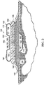
- FIGURE 2 shows the offloading pressure component 170 in the inflated state.
- the offloading pressure component 170 includes a relief valve 160 that is operable to release air from the offloading pressure component 170.
- the relief valve 160 may be configured to prevent the pressure from exceeding a maximum predetermined value within the offloading pressure component 170 or may be used to prevent the offloading pressure component 170 from bursting if too much air or pressure is exerted within the offloading pressure component 170.
- the relief valve 160 includes a spring holding the relief valve 160 closed. When the internal pressure exceeds the force of the spring, the relief valve 160 opens and air is released from the offloading pressure component 170 until the pressure drops below the force exerted by the spring.
- a user may manually open the relief valve 160 for deflating the offloading pressure component 170. Additionally or alternatively, the relief valve 160 may be automatically controlled by the onboard control unit 164 or by an external control unit for maintaining a desired pressure or state within the offloading pressure component 170.
- the offloading pressure component 170 forms an annular or donut shape.
- An interior region of the donut shaped, offloading pressure component 170 may substantially encompass the tissue site 110 for enabling the inflated offloading pressure component 170 to offload pressure to the external boundaries or beyond of the tissue site 110.
- the offloading pressure component 170 may be circular, oval, square, triangular, or any other desired shape that best conforms to the size and shape of the tissue site 110.
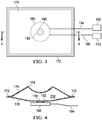
- FIGURE 3-4 another illustrative embodiment of the offloading pressure component 170 is presented.
- This embodiment illustrates the offloading pressure component 170 having a rectangular shape in plan view. The embodiment is shown in a deflated state in FIGURE 3.
- FIGURE 4 presents the offloading pressure component 170 of FIGURE 3 as a cross section in an inflated state.
- the cross section of the offloading pressure component 170 shows a concave pillow shape to the offloading pressure component 170.
- the reduced-pressure source 180 is illustrated beneath (for the orientation shown) the offloading pressure component 170.
- the offloading pressure component 170 includes an aperture 178 (shown in FIGURE 4 ) that is in fluid communication with the exhaust port 190 of the reduced-pressure source 180.
- a sealing ring 192 such as an O-ring, is seated between the exhaust port 190 of the reduced-pressure source 180 and the aperture 178 of the offloading pressure component 170.
- the sealing ring 192 is operable to maintain a seal that enables gaseous communication between the exhaust port 190 and the aperture 178 of the offloading pressure component 170.
- the sealing ring 192 may be coupled to both the exhaust port 190 and the offloading pressure component 170 for maintaining a fluid seal.
- the coupling may be made by any technique, e.g., welding (ultrasonic or RF or other weld), bonding, adhesives, or cements.
- the bottom layer 176 of the offloading pressure component 170 which may be formed from a transparent material, may be melted with a laser to the sealing ring 192.
- the bottom layer 176 of the offloading pressure component 170 is coupled to the sealing ring 192 and then top layer 174 is coupled to the bottom layer 176.
- the offloading pressure component 170 may be formed with an inflatable spigot (not shown) that engages the sealing ring 192.
- the inflatable spigot which may receive positive pressure exhaust from the reduced-pressure source 180, is like a shaft in an o-ring. As the inflatable spigot inflates or experiences more internal pressure, the strength of the seal between the spigot and sealing ring 192 increases.
- the top layer 174 of the offloading pressure component 170 is formed from a material not affected by heat from ultrasonic welding and the bottom layer 176 is formed from a material that is affected by heat from ultrasonic welding.
- the offloading pressure component 170 may placed adjacent to the sealing ring 192 with the bottom layer 176 adjacent to the sealing ring 192 and then exposed to the ultrasonic welding process.
- the sealing ring 192 is coupled to the bottom layer 176.
- the reduced-pressure source 180 includes electrical lead lines 194 for receiving power from an external power source 200.
- the reduced-pressure source 180 may also include data lines 196 for communicating data signals between the reduced-pressure source 180 and an external control unit 210.
- the external control unit 210 may contain sensors, processing units, alarm indicators, memory, databases, software, display units, and a user interface that further facilitate the application of reduced pressure treatment to the tissue site 110.
- a sensor or switch (not shown) may be disposed at or near the reduced-pressure source 180 to determine a source pressure generated by the reduced-pressure source 180 or a pressure within the offloading pressure component 170.
- the sensor may communicate with a processing unit in the external control unit 210 that monitors and controls the reduced pressure that is delivered by the reduced-pressure source 180 or the pressure within the offloading pressure component 170.
- a processing unit in the external control unit 210 that monitors and controls the reduced pressure that is delivered by the reduced-pressure source 180 or the pressure within the offloading pressure component 170.
- an alarm may be triggered in response to the pressure exceeding a threshold, such as, but not limited to, a maximum pressure threshold or a minimum pressure threshold.
- the offloading pressure component 170 comprises a top layer 174 (or first layer) and a bottom layer 176 (or second layer).
- the top layer 174 and the bottom layer 176 may be made of any type of flexible film material such as, but not limited to, plastic or rubber. In some embodiments, the top layer 174 and the bottom layer 176 may be made of different materials.
- the top layer 174 and the bottom layer 176 may be coupled together by any suitable means, such as, but not limited to, welding or adhesively bonding the two layers together, or formed as an integral member.
- FIGURES 3 and 4 depict weld lines 172 that connect the top layer 174 and the bottom layer 176 together.
- the top layer 174 and the bottom layer 176 form the inner space 202 that is operable to receive air from an exhaust port 190 through an aperture 178 located on the bottom layer 176.
- the top layer 174 may be formed with a concave area that is over the tissue site being treated.
- the offloading pressure component 170 may comprise any number of layers.
- the offloading pressure component 170 may comprise a single layer that is sealed directly to the cover 140 to create the inner space 202 between the single layer and the cover 140.
- the offloading pressure component 170 may comprise more than two layers.
- the offloading pressure component 170 may have multiple layers between the top layer 174 and the bottom layer 176 for creating a stack of cushioned air within the inner space 202, or a cushion within a cushion.
- the reduced pressure treatment system 100 includes an offloading pressure component 170.
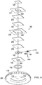
- FIGURE 5 which shows the offloading pressure component 170 in the inflated state
- the weight or force 220 of a patient's body or body part is being supported by a surface 222, such as a bed.
- the offloading pressure component 170, or inflatable cushion includes an inflatable bladder 224.
- the weight or force 220 exerted by the patient is supported by the force 226 that is normal to and outboard of the tissue site 110 being treated.
- the distributed force 226 counters the force 220 without directly applying force onto the tissue site 110 itself.
- the offloading pressure component 170 is shown as an inflatable annular member having the inflatable bladder 224.
- a central portion 225 may interface with the pump 180 to receive positive pressure exhaust from an outlet port 190.
- a charcoal filter 244 may be placed between the outlet port 190 and an inlet or aperture 178 of the offloading pressure component 170.
- the reduced-pressure dressing assembly 102 includes a treatment manifold 120, or interface layer, adapted to be positioned at the tissue site 110, and a seal layer 231 to seal the reduced-pressure dressing assembly 102 around the tissue site 110.
- a first manifold layer 232 is positioned in fluid communication with the treatment manifold 120 to distribute the reduced pressure to the treatment manifold 120 and the tissue site 110.
- An absorbent layer 130 is positioned in fluid communication with the first manifold layer 232 to absorb liquid from at least one of the first manifold layer 232, the treatment manifold 120, and the tissue site 110.
- a diverter layer 234, which may contain one or more apertures 246, may be positioned adjacent to the absorbent layer 130.
- a second manifold layer 236 may be positioned in fluid communication with the diverter layer 234, and a liquid-air separator 238 may be positioned adjacent the second manifold layer 236.
- a cover 140, or drape, is positioned adjacent to the second liquid-air separator 238.
- An odor filter or odor-treating material may also be positioned within the reduced-pressure dressing assembly 102.
- the reduced-pressure dressing assembly 102 includes a pump 180 that may be integrated into the reduced-pressure dressing assembly 102 between the liquid-air separator 238 and the cover 140.
- the pump 180 may be a micropump that is small and light enough such that the reduced-pressure dressing assembly 102 (including the micropump) is able to be maintained on the tissue site 110.
- the pump 180 may be disposed within the reduced-pressure dressing assembly 102 to avoid conduits and external canisters for collection of wound exudate.
- the pump 180 includes the outlet port 190.
- the outlet port 190 is in fluid communication with an aperture 240 in the cover 140.
- a sealing ring 192 e.g., and O-ring or seal, may be used to form a fluid seal with the outlet port 190 or to couple the offloading pressure component 170 and the reduced-pressure dressing assembly 102.
- the cover 140 may be sealed around an outlet port of the pump 180 such that gas from the pump 180 is able to exhaust directly through the aperture 240.
- the outlet port 190 of the pump 180 is oriented in a direction away from the hydrophobic filter to avoid adding air under the cover 140 and to allow the air to enter the inflatable component 170, or cushion.
- the air exhausts through the aperture 240 in the cover 140, which may include a one-way valve. Alternatively, the air or other gas could be exhausted through a gas-permeable portion of the cover 140.
- the piezoelectric actuator associated with the pump 180 may, at times, be driven at different frequencies to act as a buzzer or vibrating alert system.
- the alert system may be used to alert a user to an alarm condition such as the presence of a leak in the cover 140, a change in reduced pressure as measured by a sensor, an indication that the dressing assembly 102 has absorbed a maximum capacity of liquid as may be indicated by an indicator, or an indication that one or more layers are no longer manifolding reduced pressure efficiently.
- Control electronics, or control unit 210 may be utilized to control operation of the pump 180.
- the control unit 210 may be analog or digital and be configured with a regulator (not shown) to regulate speed or duty cycle at which the pump 180 operates.
- the control unit 210 may be configured with a controller (not shown) that receives sense signals from sensors or switches (not shown).
- the sensors may be disposed throughout the reduced-pressure dressing assembly 102 to sense parameters, such as pressure, temperature, moisture, chemistry, odor, or any other parameter that may be utilized in managing and controlling the pump 180.
- the control unit 210 includes a computer processor.
- the control unit 210 may include a programmable gate array.
- the control unit 210 may also be formed using analog electronic components. It should be understood that the control unit 210 may include any form of digital or analog components to perform functionality as described herein.
- the control unit 210 may include electronics that may be utilized to monitor each of the four parameters and generate an alarm signal (e.g., high-pitched beep, vibration, or light) using a speaker (not shown), vibrator (not shown), or illumination device (not shown), such as a light emitting diode (LED), to notify a medical professional, patient, or family member that a parameter is outside of a safe range. For example, if a pressure at the wound site 110 is below a therapeutic level, a continuous tone may be generated.
- an alarm signal e.g., high-pitched beep, vibration, or light
- a speaker not shown
- vibrator not shown
- illumination device not shown
- a continuous tone may be generated.
- An internal power source e.g., a battery 162 may be utilized to provide electric power to the pump 180 and the control unit 210.
- the battery 162 may have any size and shape configuration and be housed in any material, such as polymer, to accommodate weight and size of the reduced-pressure dressing assembly 102.
- the battery 162 may be rechargeable.
- the battery 162 may be disposed within or outside of the reduced-pressure dressing assembly 102 and be positioned in such a manner as to allow for easy replacement or recharging.
- the battery 162 may be configured with a voltage level sensor (not shown) that is monitored by the control unit 210 for determination of a low power level.
- the battery 162 may be directly connected with the pump 180.
- the battery 162 may be connected to the control unit 210 that may use power from the battery 162 to drive the pump 180.
- the control unit 210 may provide continuous power, modulated power, such as a pulsewidth modulated (PWM) signal, to drive the pump 180.
- PWM pulsewidth modulated
- the seal layer 231 may be adhered to or otherwise connected to the cover 140.
- the seal layer 231 may include an aggressive or medical grade adhesive material that is strong enough to form a vacuum seal with skin around a wound of a patient.
- the seal layer 231 may be a band that has an opening 242.
- the seal layer 231 may be adhered to the diverter layer 234 and the diverter layer 234 adhered to the cover 140 to create an upper (or first) dressing portion and a lower (or second) dressing portion.
- the upper dressing portion may include the cover 140, the pump 180 and related components, the liquid-air separator 238, the second manifold layer 236, and the diverter layer 234.
- the lower dressing portion may include the absorbent layer 130, the first manifold layer 232, the seal layer 231, and the treatment manifold 120.
- the reduced-pressure dressing assembly may be configured to allow replacement of the lower dressing portion once the dressing has absorbed a maximum capacity of fluid.
- the upper dressing portion may be reused after the lower dressing portion is replaced.
- the pump 180 This allows multiple use of the pump 180, while disposable portions of the dressing assembly 102 may be replaced.
- the pump 180, control unit 210, and battery 162 may be removed from the dressing assembly 102 for reuse and the remaining layers of the dressing assembly 102 replaced.
- the absorbent layer 130 only may be replaced.
- the absorbent layer 130 and the treatment manifold 120 only may be replaced.
- the charcoal filter 244 may be utilized in the reduced-pressure dressing assembly 102 to reduce odors created by the tissue site and exhausted from the reduced-pressure dressing assembly 102.
- the charcoal filter 244 may be disposed above a valve or other output vent from the pump 180 to filter exhaust from the pump 180 prior to being released from the reduced-pressure dressing 102 into the inflatable component 170. It should be understood that the charcoal filter 244 may be alternatively configured and disposed above or below the pump 180. In another illustrative embodiment, rather than using a charcoal filter or in addition, charcoal may be integrated into any or all of the different layers utilized in the reduced-pressure dressing assembly 102.
- a method for collecting liquid in a dressing assembly positioned at a tissue site includes generating a reduced pressure using a pump positioned within the dressing assembly. A liquid is absorbed from the tissue site and is stored in the dressing assembly. The liquid is prevented from entering the pump. The method may further include maintaining the reduced pressure within the dressing and exhausting gas from the pump into an inflatable component that disperses forces that would otherwise be applied through the dressing assembly directly onto the tissue site.
- While the depicted illustrative embodiments illustrate the use of a single pump and a single offloading pressure component, alternative embodiments may include any number of pumps and offloading pressure components.
- the offloading pressure component may be supplied separately so as to provide user flexibility as to when and where the offloading pressure component may be applied.
- the disclosed embodiments may be used as part of a process or method for offloading pressure exerted on or near a tissue site in which reduced pressure is applied to promote healing of the tissue site and for reducing patient discomfort.
- the method includes applying a wound dressing assembly to cover the tissue site, and applying reduced pressure to the tissue site using a reduced-pressure source coupled to the wound dressing assembly.
- the method further includes inflating an inner space of an offloading pressure component coupled to the reduced-pressure source.
- the offloading pressure component is operable to disperse positive pressure exerted on or near the tissue site for reducing the exerted pressure to the tissue site.
- a reduced-pressure treatment system for applying reduced-pressure treatment to a tissue site includes: a wound cover for covering the tissue site an for forming a sealed space; a reduced-pressure source producing a positive pressure exhaust and reduced pressure, the reduced-pressure source for providing reduced pressure to the tissue site; and an offloading pressure component for dispersing positive pressure exerted on or near the tissue site, the offloading pressure component fluidly coupled to the reduced-pressure source for receiving at least a portion of the positive pressure exhaust.
- the offloading pressure component may be an inflatable and deflatable bladder.
- the offloading pressure component may include an aperture for coupling an exhaust port of the reduced-pressure source to the offloading pressure component, and the positive pressure exhaust from the reduced-pressure source may exit through the exhaust port and into the offloading pressure component for inflating the offloading pressure component.
- the reduced-pressure treatment system may further include an exhaust valve for limiting the flow of gas from the exhaust port into the offloading pressure component.
- the reduced-pressure treatment system may further include a sealing ring operable to maintain a seal between the exhaust port of the reduced-pressure source and the offloading pressure component.
- the reduced-pressure source may be a micro-pump disposed in the sealed space created by the cover over the tissue site.
- the offloading pressure component may include a relief valve operable to release air from the offloading pressure component.
- the reduced-pressure source may include a reduced-pressure valve that enables the reduced-pressure source to draw atmospheric air into the offloading pressure component to inflate the offloading pressure component.
- the reduced-pressure treatment system may further include at least one power source associated with the wound cover for powering the reduced-pressure source.
- the reduced-pressure source may be powered from an external power source.
- the reduced-pressure treatment system may further include a controller that controls inflation of the offloading pressure component.
- the reduced-pressure treatment system may also include a pressure sensor in communication with the controller for providing pressure readings to the controller.
- the reduced-pressure treatment system may also include an alarm in communication with the controller for indicating that the pressure readings have exceeded a threshold value.
- the offloading pressure component may include at least two layers of flexible film welded together or bonded together.
- the offloading pressure component may comprise a single layer of flexible film that has been folded and sealed at an otherwise open end.
- the offloading pressure component may be configured to store liquid collected from the tissue site.
- a system for treating a tissue site with reduced pressure includes: a reduced-pressure source that produces reduced pressure and a positive pressure exhaust; and an offloading pressure component having a deflated state and an inflated state, the offloading pressure component comprising at least one flexible wall forming an inner space of the offloading pressure component, the inner space fluidly coupled to the reduced-pressure source and operable to receive the positive pressure exhaust generated by the reduced-pressure source.
- the inner space is fluidly coupled to an exhaust port of the reduced-pressure source to receive positive pressure exhaust.
- the inner space may be formed by two layers of flexible film welded or bonded together.
- the system may further include an aperture located on one of the two layers for coupling an exhaust port of the reduced-pressure source to the offloading pressure component.
- the system may further include a sealing ring operable to maintain a seal between the exhaust port of the reduced-pressure source and the offloading pressure component.
- the system may further include a relief valve operable to release air from the offloading pressure component.
- a method for offloading pressure exerted proximate to a tissue site in which reduced pressure is applied comprising: applying a wound cover over the tissue site; applying reduced pressure to the tissue site using a reduced-pressure source coupled to the wound cover; and inflating an inner space of an offloading pressure component coupled to the reduced-pressure source, the offloading pressure component operable to disperse positive pressure exerted proximate to the tissue site.
- the reduced-pressure source may be a micropump.
- the method may further include inflating the inner space of the offloading pressure component using gas generated by the reduced-pressure source.
- the method may include inflating the inner space of the offloading pressure component using exhaust generated by the reduced-pressure source while the reduced-pressure source is supplying reduced pressure to the tissue site.
- the method may include inflating the inner space of the offloading pressure component using exhaust generated by the reduced-pressure source while the reduced-pressure source is drawing in atmospheric air.
- the method may include limiting inflation of the inner space of the offloading pressure component using an exhaust valve.
- the method may also include monitoring a pressure within the offloading pressure component using at least one sensor; and triggering an alarm in response to the pressure exceeding a threshold.
- the method may also involve storing liquid collected from the tissue site in the offloading pressure component.
- the method may also include applying a sealing ring between an exhaust port of the reduced-pressure source and the offloading pressure component in order to couple the exhaust port of the reduced-pressure source to an inner space of the offloading pressure component.
- the method may include powering the reduced-pressure source using a power source integrated within the wound cover.
- the method may involve powering the reduced-pressure source using an external power source.
- the method may also include controlling the inflation of the inner space of the offloading pressure component using an electronic controller.
- the method may further include controlling, by an electronic controller, the inflation of the inner space of the offloading pressure component in response to the electronic controller receiving a user initiated request to adjust a pressure within the inner space of the offloading pressure component.
- an offloading pressure component may be used as part of a reduced-pressure treatment system.
- a reduced-pressure source of the reduced-pressure treatment system vents positive pressure exhaust into the offloading pressure component to inflate the offloading pressure component.
- the offloading pressure component disperses forces away from the tissue site.
Landscapes
- Health & Medical Sciences (AREA)
- Heart & Thoracic Surgery (AREA)
- Veterinary Medicine (AREA)
- Engineering & Computer Science (AREA)
- Biomedical Technology (AREA)
- Life Sciences & Earth Sciences (AREA)
- Animal Behavior & Ethology (AREA)
- General Health & Medical Sciences (AREA)
- Public Health (AREA)
- Vascular Medicine (AREA)
- Anesthesiology (AREA)
- Hematology (AREA)
- Otolaryngology (AREA)
- Business, Economics & Management (AREA)
- Emergency Management (AREA)
- Physics & Mathematics (AREA)
- General Physics & Mathematics (AREA)
- Media Introduction/Drainage Providing Device (AREA)
- External Artificial Organs (AREA)
Description
- The disclosure relates generally to reduced-pressure medical treatment systems and more particularly, but not by way of limitation, to inflatable off-loading wound dressing assemblies, systems, and methods.
- Clinical studies and practice have shown that providing a reduced pressure in proximity to a tissue site augments and accelerates the growth of new tissue at the tissue site. The applications of this phenomenon are numerous, but one particular application of reduced pressure involves treating wounds. This treatment (frequently referred to in the medical community as "negative pressure wound therapy," "reduced-pressure therapy," or "vacuum therapy") provides a number of benefits, including migration of epithelial and subcutaneous tissues, improved blood flow, and micro-deformation of tissue at the wound site. Together these benefits result in increased development of granulation tissue and faster healing times. Typically, reduced pressure is applied by a reduced-pressure source to tissue through a porous pad or other manifold device. In many instances, wound exudate and other liquids from the tissue site are collected within a canister to prevent the liquids from reaching the reduced-pressure source. At times, the tissue site being treated is at a pressure point on the patient, e.g., on the back of a bedridden patient.
-
WO2009/114624 discloses an apparatus and method for delivering reduced pressure to a wound using a dressing which includes an inflatable component. - The invention is defined in the appended claims and provides a reduced-pressure treatment system for applying reduced-pressure treatment to a tissue site, the system comprising: a wound cover, for covering the tissue site and for forming a sealed space; a reduced-pressure source producing a positive pressure exhaust and reduced pressure, the reduced-pressure source for providing reduced pressure to the tissue site; and an offloading pressure component for dispersing positive pressure exerted on or near the tissue site, the offloading pressure component fluidly coupled to the reduced pressure source for receiving at least a portion of the positive pressure exhaust; wherein the offloading pressure component includes a relief valve for releasing air from the offloading pressure component.
- A selection of optional features is set out in the dependent claims.
- Insofar as the term invention or embodiment is used in the following, or features are presented as being optional, this should be interpreted in such a way that the only protection sought is that of the invention claimed.
- Reference(s) to "embodiment(s)" throughout the description which are not under the scope of the appended claims merely represent possible exemplary executions and are not part of the present invention.
-
-
FIGURE 1 is a schematic, cross-sectional side view of a reduced-pressure treatment system having an offloading pressure component according to an illustrative embodiment shown in a deflated state; -
FIGURE 2 is a schematic, cross-sectional side view of the reduced-pressure treatment system ofFIGURE 1 in which the offloading pressure component is in an inflated state according to an illustrative embodiment; -
FIGURE 3 is a schematic, top view of a reduced-pressure treatment system having an offloading pressure component according to another illustrative embodiment; -
FIGURE 4 is a schematic, cross-sectional view of the offloading pressure component ofFIGURE 3 taken along line 4-4; and -
FIGURE 5 is a schematic, cross-sectional view of an illustrative embodiment of a reduced-pressure treatment system shown with an inflated offloading pressure component dispersing a force exerted by a patient's weight; and -
FIGURE 6 is a schematic, exploded, perspective view of the reduced-pressure treatment system ofFIGURE 5 . - In the following detailed description of several illustrative embodiments, reference is made to the accompanying drawings that form a part hereof, and in which is shown by way of illustration specific preferred embodiments in which the invention may be practiced. These embodiments are described in sufficient detail to enable those skilled in the art to practice the invention, and it is understood that other embodiments may be utilized and that logical structural, mechanical, electrical, and chemical changes may be made without departing from the scope of the invention. To avoid detail not necessary to enable those skilled in the art to practice the embodiments described herein, the description may omit certain information known to those skilled in the art. The following detailed description is, therefore, not to be taken in a limiting sense, and the scope of the illustrative embodiments are defined only by the appended claims.
- Referring to the drawings and initially and primarily to
FIGURE 1 , a cross-sectional side view of a reduced-pressure treatment system 100 according to an illustrative embodiment is presented. The reduced-pressure treatment system 100 is applied to atissue site 110, such as a wound. The tissue site may be a wound or defect located on or within any tissue, including but not limited to, bone tissue, adipose tissue, muscle tissue, neural tissue, dermal tissue, vascular tissue, connective tissue, cartilage, tendons, or ligaments. The tissue site may further refer to areas of any tissue that are not necessarily wounded or defective, but are instead areas in which it is desired to add or promote the growth of additional tissue. For example, reduced pressure tissue treatment may be used in certain tissue areas to grow additional tissue that may be harvested and transplanted to another tissue location. - The reduced-
pressure treatment system 100 includes adressing assembly 102 and a reduced-pressure source 180, which may be integral to or separate from thedressing assembly 102. Thedressing assembly 102 of the illustrative embodiment ofFIGURE 1 includes acover 140, the reduced-pressure source 180 coupled to or incorporated into thecover 140 for providing reduced pressure treatment to thetissue site 110, and anabsorbent layer 130 for absorbing exudates and other liquids drawn from thetissue site 110. The reduced-pressure treatment system 100 includes anoffloading pressure component 170 for dispersing positive pressure exerted on or near thetissue site 110. Theoffloading pressure component 170 may, for example, allow a patient to lay on their back even though the tissue site being treated is on their back because theoffloading pressure component 170 offloads or prevents a substantial load from being placed on thetissue site 110. Theoffloading pressure component 170 is an inflatable bladder or inflatable and deflatable bladder. - In addition, in certain embodiments, the reduced-
pressure treatment system 100 may include anonboard control unit 164, an internal power source, such as abattery 162, and one or more sensors (not shown), such as, but not limited to, a pressure sensor for monitoring a pressure level exerted by the reduced-pressure source 180 on thetissue site 110, or for monitoring a pressure level within theoffloading pressure component 170. As used herein "or" does not require mutual exclusivity. The one or more sensors may provide pressure readings to theonboard control unit 164 or an external reduced-pressure treatment unit for enabling theonboard control unit 164 to adjust the operations of the reduced-pressure treatment system 100. - The
cover 140, or drape, may be made of a flexible material that covers thetissue site 110 to protect thetissue site 110 from the external environment and forms or helps form a fluid seal. Thecover 140 may extend beyond a perimeter of thetissue site 110 and may include an adhesive, bonding agent, or other attachment device on a peripheral portion of thecover 140 to secure thecover 140 to tissue adjacent to thetissue site 110. Thecover 140 may be used to create a sealedspace 141 over thetissue site 110. The adhesive disposed on thecover 140 may be used to form a fluid seal between the tissue and thecover 140 to prevent leakage of reduced pressure from thetissue site 110. - The
absorbent layer 130 is disposed beneath (for the orientation shown) thecover 140 and is used to absorb exudates and other liquids drawn from thetissue site 110. Theabsorbent layer 130 may be integrated with thecover 140 or theabsorbent layer 130 may be a separate component of the reduced-pressure treatment system 100. Theabsorbent layer 130 may be made from any material capable of absorbing liquid, such as exudate, from thetissue site 110. In one illustrative embodiment, theabsorbent layer 130 is made from a super absorbent fiber. The super absorbent fibers may hold onto or bond to the liquid in conjunction with a physical or chemical change to the fibers. In one illustrative, non-limiting example, the super absorbent fiber may include the Super Absorbent Fiber (SAF) material from Technical Absorbents®, Ltd. In some embodiments, theabsorbent layer 130 may include an odor adsorption material (not shown) such as, but not limited to, activated charcoal for reducing or eliminating the odor associated with the collected exudates. - The reduced-
pressure treatment system 100 may also include atreatment manifold 120 adapted to be positioned proximate to thetissue site 110. Thetreatment manifold 120 may be partially or fully in contact with thetissue site 110 that is being treated by the reduced-pressure treatment system 100. When thetissue site 110 is a wound, thetreatment manifold 120 may partially or fully fill the wound bed. Thetreatment manifold 120 may be any size, shape, or thickness depending on a variety of factors, such as the type of treatment being implemented or the nature and size of thetissue site 110. For example, the size and shape of thetreatment manifold 120 may be customized by a user to cover a particular portion of thetissue site 110, or to fill or partially fill thetissue site 110. Thetreatment manifold 120 may have, for example, a square shape, or may be shaped as a circle, oval, polygon, an irregular shape, or any other shape. - The
treatment manifold 120 is a material, e.g., a foam material, that distributes reduced pressure to thetissue site 110 when thetreatment manifold 120 is in contact with or near thetissue site 110. The foam material may be either hydrophobic or hydrophilic. In one illustrative, non-limiting example, thetreatment manifold 120 is an open-cell, reticulated polyurethane foam, such as GranuFoam® dressing available from Kinetic Concepts, Inc. of San Antonio, Texas. - In the example in which the
treatment manifold 120 is made from a hydrophilic material, thetreatment manifold 120 also functions to wick fluid away from thetissue site 110, while continuing to provide reduced pressure to thetissue site 110 as a manifold. The wicking properties of the treatment manifold 120 draw fluid away from thetissue site 110 by capillary flow or other wicking mechanisms. An example of a hydrophilic foam is a polyvinyl alcohol, open-cell foam, such as V.A.C. WhiteFoam® dressing available from Kinetic Concepts, Inc. of San Antonio, Texas. Other hydrophilic foams may include those made from polyether. Other foams that may exhibit hydrophilic characteristics include hydrophobic foams that have been treated or coated to provide hydrophilicity. - The
treatment manifold 120 may be constructed from bioresorbable materials that do not have to be removed from a patient's body following use of the reduced-pressure dressing assembly 102. Suitable bioresorbable materials may include, without limitation, a polymeric blend of polylactic acid (PLA) and polyglycolic acid (PGA). The polymeric blend may also include, without limitation, polycarbonates, polyfumarates, and capralactones. Thetreatment manifold 120 may further serve as a scaffold for new cell-growth, or a scaffold material may be used in conjunction with thetreatment manifold 120 to promote cell-growth. A scaffold is a substance or structure used to enhance or promote the growth of cells or formation of tissue, such as a three-dimensional porous structure that provides a template for cell growth. Illustrative examples of scaffold materials include calcium phosphate, collagen, PLA/PGA, coral hydroxy apatites, carbonates, or processed allograft materials. - In the illustrative embodiment of
FIGURE 1 , reduced pressure is applied to thetissue site 110 by the reduced-pressure source 180. In one embodiment, the reduced-pressure source 180 is amicropump 191 that may be, for example, an electrically-driven vacuum pump and in other embodiments may be a non-motor driven pump. In still other illustrative embodiments, the reduced-pressure source 180 may be remote but fluidly coupled to thedressing assembly 102. In such embodiments, a dual lumen conduit may be used with one lumen delivering reduced pressure to the tissue site and one lumen delivering positive pressure to the inflatable portions, e.g., the offloadingpressure component 170. - The
micropump 191 may be a micropump that is small and light enough that thecover 140 is able to be maintained on thetissue site 110 with themicropump 191 included. Furthermore, the size and weight of themicropump 191 should be such that thecover 140 does not pull or otherwise adversely affect thetissue site 110. In one embodiment, themicropump 191 may be a disk pump having a piezoelectric actuator. In this and other non-motor-driven pump embodiments, the pump used to generate reduced pressure is not driven by an electric motor or other motor. In the case of the piezoelectric pump, the pump generates fluid flow by supplying an electric current to a piezoelectric actuator. The piezoelectric actuator vibrates when supplied with electric current, and these vibrations are used to generate a pressure differential within a pump cavity (relative to the ambient environment of the pump). The piezoelectric actuator may be positioned directly adjacent to the pump cavity such that the vibration of the actuator is directly transformed into pressure waves within the pump cavity, or alternatively the piezoelectric actuator may be positioned adjacent a diaphragm that transmits the vibrations of the piezoelectric actuator to the pump cavity. In an alternative embodiment, themicropump 191 may be a peristaltic pump that is used for pumping a variety of fluids. It should be understood that alternative pump technologies may also be utilized and that rotary, linear, or other configurations of pumps may be utilized. In still another embodiment, reduced pressure may be supplied from a location remote from thecover 140. - In another illustrative embodiment, the reduced-
pressure source 180 may instead be a manually-actuated or manually-charged pump that does not require electrical power. In one embodiment, the reduced-pressure source 180 may be integrated as part of thecover 140. The reduced-pressure source 180 supplies reduced pressure to thetissue site 110 and draws exudates and other liquids from thetissue site 110, through thetreatment manifold 120 and into theabsorbent layer 130. - Reduced pressure generally refers to a pressure less than the ambient pressure at a tissue site that is being subjected to treatment. In most cases, this reduced pressure will be less than the atmospheric pressure at which the patient is located. Alternatively, the reduced pressure may be less than a hydrostatic pressure associated with tissue at the
tissue site 110. Reduced pressure may initially generate fluid flow in the area of thetissue site 110. As the hydrostatic pressure around thetissue site 110 approaches the desired reduced pressure, the flow may subside, and the reduced pressure is then maintained. Unless otherwise indicated, values of pressure stated herein are gauge pressures. Similarly, references to increases in reduced pressure typically refer to a decrease in absolute pressure, while decreases in reduced pressure typically refer to an increase in absolute pressure. - In the illustrative embodiment of
FIGURE 1 , the reduced-pressure source 180 includes anexhaust port 190 for exhausting gas (positive pressure exhaust) generated during operation of the reduced-pressure source 180. The gas exhausted through theexhaust port 190 is used to inflate the offloadingpressure component 170, which may comprise an inflatable bladder. In some embodiments, the reduced-pressure source 180 may include anexhaust valve 188 for controlling or limiting the flow of the gas exhausted by the reduced-pressure source 180. For instance, in one embodiment, theexhaust valve 188 is operable to control or limit exhaust gas flow through either anexhaust port path 181 leading out ofexhaust port 190 to theinflatable device 170 or to anatmospheric exhaust path 183 that directs the gas exhausted from the reduced-pressure source 180 to enter the surrounding atmosphere or be delivered to another location. While not explicitly shown, theatmospheric exhaust path 183 may include an odor filter, e.g., a charcoal filter (see, e.g.,charcoal filter 244 inFIG. 6 ). The flow may be continuous or intermittent. - For example, the
exhaust valve 188, or positive-pressure valve, may be configured to exhaust all or a portion of the gas through theatmospheric exhaust path 183 if the offloadingpressure component 170 is to remain in a deflated or a semi-deflated state or is already inflated. In one embodiment, the operation of theexhaust valve 188 may be controlled automatically by theonboard control unit 164 or by an external control unit. For example, theonboard control unit 164 may store a set of preconfigured parameters, such as, but not limited to, the desired pressure, frequency of inflation, and the duration of inflation. In addition, or in lieu of, in some embodiments, the operation of theexhaust valve 188 may be manually controlled by a caregiver or a patient by either manually toggling a switch or by the push of a button on a control unit. - In one illustrative embodiment, the positive pressure exhaust from the reduced-
pressure source 180 is delivered to theexhaust valve 188 at an inlet. The valve may contain a pressure regulator that provides a safety overpressure release. In other words, if the pressure experienced by the overpressure release is beyond a threshold, the overpressure release will allow fluid to exit. Downstream of the overpressure release may be a (1) manual input valve for bleeding or directing all or a portion of the positive pressure toatmosphere 183 or (2) an automated input that will release positive pressure beyond a threshold. - In addition, in some embodiments, the reduced-
pressure source 180 may include a reduced-pressure valve 189, or purge valve, disposed adjacent to agas inlet 184 of the reduced-pressure source 180. The reduced-pressure valve 189 may be used to redirect, control, or limit the flow of reduced pressure to either an atmospheric reduced-pressure path 185 for receiving airflow from the surrounding atmosphere, or to a tissue site reduced-pressure path 187 for providing reduced pressure to thetissue site 110. For example, in one embodiment, the reduced-pressure source 180 is operable to draw air from the surrounding atmosphere using the reduced-pressure valve 189, and exhaust the drawn air through theexhaust port 190 to quickly inflate the offloadingpressure component 170. Alternatively, or in addition to, in some embodiments, the reduced-pressure source 180 is operable to draw air from the surrounding atmosphere, in conjunction with simultaneously providing reduced pressure to thetissue site 110, for inflating the offloadingpressure component 170, such as when the reduced pressure being applied to thetissue site 110 is insufficient to produce enough exhaust for inflating the offloadingpressure component 170 by itself or as quickly as desired. - In one embodiment, a liquid-air separator (not shown) is positioned between the
absorbent layer 130 and thegas inlet 184 that prevents liquid from entering the reduced-pressure source 180 and allows gas (e.g., reduced pressure) to be communicated for maintaining reduced pressure at thetissue site 110. The liquid-air separator may be a hydrophobic or oleophobic filter that prevents passage of liquids, but allows gaseous communication. Examples of a suitable hydrophobic material include an expanded PTFE laminate, such as a hydrophobic medical membrane manufactured by WL Gore & Associates, Newark, Delaware. In one illustrative embodiment, the PTFE laminate may be a laminate and may have a 1.0 micron reference pore size on non-woven polyester with a thickness range of .0068mm- .0135mm. An example of a suitable oleophobic material includes an oleophobic expanded ptfe membrane having a 1.0 micron reference pore size on non-woven polyester with a thickness range of 0.15mm-0.39mm. The oleophobic membrane may have a minimum air flow of 12 LPM/cm2/bar (15 PSI) and a minimum water entry pressure of 0.8 bar (12.0 PSI). Alternatively, the substantially planar liquid-air separator may be a gravity-based barrier system, or a device that includes a hydrophilic surface to encourage condensation or other separation of liquid from a fluid stream when the fluid stream passes over the surface. Other examples of the liquid-air separator may include sintered metals, sintered nylons, or any other material or device that is capable of separating liquid from a fluid stream, or that is otherwise capable of substantially preventing the passage of liquid while allowing the passage of gases. - With reference now primarily to
FIGURES 1-2 , in accordance with a disclosed illustrative embodiment, the offloadingpressure component 170 is coupled to thecover 140 and the reduced-pressure source 180, and is operable to receive theexhaust port 190 of the reduced-pressure source 180 through an aperture 178 (FIG. 4 ) of the offloadingpressure component 170. As described above, in one embodiment, positive pressure exhaust generated during operation of the reduced-pressure source 180 exits through theexhaust port 190 and into aninner space 202 of the offloadingpressure component 170 and inflates the offloadingpressure component 170.FIGURE 1 shows the offloadingpressure component 170 in a deflated state andFIGURE 2 shows the offloadingpressure component 170 in the inflated state. - In the depicted embodiment, the offloading
pressure component 170 includes arelief valve 160 that is operable to release air from the offloadingpressure component 170. In one embodiment, therelief valve 160 may be configured to prevent the pressure from exceeding a maximum predetermined value within the offloadingpressure component 170 or may be used to prevent the offloadingpressure component 170 from bursting if too much air or pressure is exerted within the offloadingpressure component 170. In one illustrative embodiment, therelief valve 160 includes a spring holding therelief valve 160 closed. When the internal pressure exceeds the force of the spring, therelief valve 160 opens and air is released from the offloadingpressure component 170 until the pressure drops below the force exerted by the spring. In some embodiments, a user may manually open therelief valve 160 for deflating the offloadingpressure component 170. Additionally or alternatively, therelief valve 160 may be automatically controlled by theonboard control unit 164 or by an external control unit for maintaining a desired pressure or state within the offloadingpressure component 170. - In one illustrative embodiment, the offloading
pressure component 170 forms an annular or donut shape. An interior region of the donut shaped, offloadingpressure component 170 may substantially encompass thetissue site 110 for enabling the inflatedoffloading pressure component 170 to offload pressure to the external boundaries or beyond of thetissue site 110. The offloadingpressure component 170 may be circular, oval, square, triangular, or any other desired shape that best conforms to the size and shape of thetissue site 110. - Referring now primarily to
FIGURE 3-4 , another illustrative embodiment of the offloadingpressure component 170 is presented. This embodiment illustrates the offloadingpressure component 170 having a rectangular shape in plan view. The embodiment is shown in a deflated state inFIGURE 3. FIGURE 4 presents the offloadingpressure component 170 ofFIGURE 3 as a cross section in an inflated state. The cross section of the offloadingpressure component 170 shows a concave pillow shape to the offloadingpressure component 170. The reduced-pressure source 180 is illustrated beneath (for the orientation shown) the offloadingpressure component 170. The offloadingpressure component 170 includes an aperture 178 (shown inFIGURE 4 ) that is in fluid communication with theexhaust port 190 of the reduced-pressure source 180. In some embodiments, a sealingring 192, such as an O-ring, is seated between theexhaust port 190 of the reduced-pressure source 180 and theaperture 178 of the offloadingpressure component 170. The sealingring 192 is operable to maintain a seal that enables gaseous communication between theexhaust port 190 and theaperture 178 of the offloadingpressure component 170. - In one illustrative embodiment, the sealing
ring 192 may be coupled to both theexhaust port 190 and the offloadingpressure component 170 for maintaining a fluid seal. The coupling may be made by any technique, e.g., welding (ultrasonic or RF or other weld), bonding, adhesives, or cements. As another approach to coupling, thebottom layer 176 of the offloadingpressure component 170, which may be formed from a transparent material, may be melted with a laser to thesealing ring 192. In another illustrative embodiment, thebottom layer 176 of the offloadingpressure component 170 is coupled to thesealing ring 192 and thentop layer 174 is coupled to thebottom layer 176. - In another illustrative embodiment, the offloading
pressure component 170 may be formed with an inflatable spigot (not shown) that engages the sealingring 192. The inflatable spigot, which may receive positive pressure exhaust from the reduced-pressure source 180, is like a shaft in an o-ring. As the inflatable spigot inflates or experiences more internal pressure, the strength of the seal between the spigot and sealingring 192 increases. In still another illustrative embodiment, thetop layer 174 of the offloadingpressure component 170 is formed from a material not affected by heat from ultrasonic welding and thebottom layer 176 is formed from a material that is affected by heat from ultrasonic welding. The offloadingpressure component 170 may placed adjacent to thesealing ring 192 with thebottom layer 176 adjacent to thesealing ring 192 and then exposed to the ultrasonic welding process. Thus, the sealingring 192 is coupled to thebottom layer 176. - In the depicted embodiment of
FIGURE 3 , the reduced-pressure source 180 includeselectrical lead lines 194 for receiving power from anexternal power source 200. In one embodiment, the reduced-pressure source 180 may also includedata lines 196 for communicating data signals between the reduced-pressure source 180 and anexternal control unit 210. Theexternal control unit 210 may contain sensors, processing units, alarm indicators, memory, databases, software, display units, and a user interface that further facilitate the application of reduced pressure treatment to thetissue site 110. In one example, a sensor or switch (not shown) may be disposed at or near the reduced-pressure source 180 to determine a source pressure generated by the reduced-pressure source 180 or a pressure within the offloadingpressure component 170. The sensor may communicate with a processing unit in theexternal control unit 210 that monitors and controls the reduced pressure that is delivered by the reduced-pressure source 180 or the pressure within the offloadingpressure component 170. In one embodiment, an alarm may be triggered in response to the pressure exceeding a threshold, such as, but not limited to, a maximum pressure threshold or a minimum pressure threshold. - Referring primarily to
FIGURE 4 , in one embodiment, the offloadingpressure component 170 comprises a top layer 174 (or first layer) and a bottom layer 176 (or second layer). Thetop layer 174 and thebottom layer 176 may be made of any type of flexible film material such as, but not limited to, plastic or rubber. In some embodiments, thetop layer 174 and thebottom layer 176 may be made of different materials. Thetop layer 174 and thebottom layer 176 may be coupled together by any suitable means, such as, but not limited to, welding or adhesively bonding the two layers together, or formed as an integral member. For example,FIGURES 3 and 4 depictweld lines 172 that connect thetop layer 174 and thebottom layer 176 together. Thetop layer 174 and thebottom layer 176 form theinner space 202 that is operable to receive air from anexhaust port 190 through anaperture 178 located on thebottom layer 176. Thetop layer 174 may be formed with a concave area that is over the tissue site being treated. - Although
FIGURE 4 depicts an embodiment comprising of two layers, in alternative embodiments, the offloadingpressure component 170 may comprise any number of layers. For example, in one embodiment, the offloadingpressure component 170 may comprise a single layer that is sealed directly to thecover 140 to create theinner space 202 between the single layer and thecover 140. In other embodiments, the offloadingpressure component 170 may comprise more than two layers. For example, in one embodiment, the offloadingpressure component 170 may have multiple layers between thetop layer 174 and thebottom layer 176 for creating a stack of cushioned air within theinner space 202, or a cushion within a cushion. - Referring now primarily to
FIGURES 5-6 , another illustrative embodiment of a reducedpressure treatment system 100 with a dressingassembly 102 is presented. The reducedpressure treatment system 100 includes an offloadingpressure component 170. InFIGURE 5 , which shows the offloadingpressure component 170 in the inflated state, the weight or force 220 of a patient's body or body part is being supported by asurface 222, such as a bed. The offloadingpressure component 170, or inflatable cushion, includes aninflatable bladder 224. With respect to a free body diagram, the weight orforce 220 exerted by the patient is supported by theforce 226 that is normal to and outboard of thetissue site 110 being treated. The distributedforce 226 counters theforce 220 without directly applying force onto thetissue site 110 itself. - The offloading
pressure component 170 is shown as an inflatable annular member having theinflatable bladder 224. Acentral portion 225 may interface with thepump 180 to receive positive pressure exhaust from anoutlet port 190. Acharcoal filter 244 may be placed between theoutlet port 190 and an inlet oraperture 178 of the offloadingpressure component 170. - The reduced-
pressure dressing assembly 102 includes atreatment manifold 120, or interface layer, adapted to be positioned at thetissue site 110, and aseal layer 231 to seal the reduced-pressure dressing assembly 102 around thetissue site 110. Afirst manifold layer 232 is positioned in fluid communication with thetreatment manifold 120 to distribute the reduced pressure to thetreatment manifold 120 and thetissue site 110. Anabsorbent layer 130 is positioned in fluid communication with thefirst manifold layer 232 to absorb liquid from at least one of thefirst manifold layer 232, thetreatment manifold 120, and thetissue site 110. Adiverter layer 234, which may contain one ormore apertures 246, may be positioned adjacent to theabsorbent layer 130. Asecond manifold layer 236 may be positioned in fluid communication with thediverter layer 234, and a liquid-air separator 238 may be positioned adjacent thesecond manifold layer 236. Acover 140, or drape, is positioned adjacent to the second liquid-air separator 238. An odor filter or odor-treating material may also be positioned within the reduced-pressure dressing assembly 102. - In addition to the layers of the reduced-
pressure dressing assembly 102 listed above, the reduced-pressure dressing assembly 102 includes apump 180 that may be integrated into the reduced-pressure dressing assembly 102 between the liquid-air separator 238 and thecover 140. Thepump 180 may be a micropump that is small and light enough such that the reduced-pressure dressing assembly 102 (including the micropump) is able to be maintained on thetissue site 110. - The
pump 180 may be disposed within the reduced-pressure dressing assembly 102 to avoid conduits and external canisters for collection of wound exudate. Thepump 180 includes theoutlet port 190. Theoutlet port 190 is in fluid communication with anaperture 240 in thecover 140. A sealingring 192, e.g., and O-ring or seal, may be used to form a fluid seal with theoutlet port 190 or to couple the offloadingpressure component 170 and the reduced-pressure dressing assembly 102. Alternatively, thecover 140 may be sealed around an outlet port of thepump 180 such that gas from thepump 180 is able to exhaust directly through theaperture 240. In the embodiment illustrated inFIGURES 5-6 , theoutlet port 190 of thepump 180 is oriented in a direction away from the hydrophobic filter to avoid adding air under thecover 140 and to allow the air to enter theinflatable component 170, or cushion. The air exhausts through theaperture 240 in thecover 140, which may include a one-way valve. Alternatively, the air or other gas could be exhausted through a gas-permeable portion of thecover 140. - When a piezoelectric-driven pump is used as the
pump 180 in thedressing assembly 102, the piezoelectric actuator associated with thepump 180 may, at times, be driven at different frequencies to act as a buzzer or vibrating alert system. The alert system may be used to alert a user to an alarm condition such as the presence of a leak in thecover 140, a change in reduced pressure as measured by a sensor, an indication that the dressingassembly 102 has absorbed a maximum capacity of liquid as may be indicated by an indicator, or an indication that one or more layers are no longer manifolding reduced pressure efficiently. - Control electronics, or
control unit 210, may be utilized to control operation of thepump 180. Thecontrol unit 210 may be analog or digital and be configured with a regulator (not shown) to regulate speed or duty cycle at which thepump 180 operates. Furthermore, thecontrol unit 210 may be configured with a controller (not shown) that receives sense signals from sensors or switches (not shown). The sensors may be disposed throughout the reduced-pressure dressing assembly 102 to sense parameters, such as pressure, temperature, moisture, chemistry, odor, or any other parameter that may be utilized in managing and controlling thepump 180. In one embodiment, thecontrol unit 210 includes a computer processor. Alternatively, thecontrol unit 210 may include a programmable gate array. Thecontrol unit 210 may also be formed using analog electronic components. It should be understood that thecontrol unit 210 may include any form of digital or analog components to perform functionality as described herein. - Four parameters are often of concern when performing reduced pressure wound treatment: (i) low pressure, (ii) excessive leak, (iii) level of absorbent layer, and (iv) battery state. The
control unit 210 may include electronics that may be utilized to monitor each of the four parameters and generate an alarm signal (e.g., high-pitched beep, vibration, or light) using a speaker (not shown), vibrator (not shown), or illumination device (not shown), such as a light emitting diode (LED), to notify a medical professional, patient, or family member that a parameter is outside of a safe range. For example, if a pressure at thewound site 110 is below a therapeutic level, a continuous tone may be generated. As another example, if theabsorbent layer 130 is saturated, then continuous beeps may be generated. If the battery drops below a certain voltage level, then a different frequency may be generated or LED may be turned on. A variety of different alarm signals may be established to notify a medical professional or the patient to take a particular action. - An internal power source, e.g., a
battery 162, may be utilized to provide electric power to thepump 180 and thecontrol unit 210. Thebattery 162 may have any size and shape configuration and be housed in any material, such as polymer, to accommodate weight and size of the reduced-pressure dressing assembly 102. In one embodiment, thebattery 162 may be rechargeable. In another embodiment, thebattery 162 may be disposed within or outside of the reduced-pressure dressing assembly 102 and be positioned in such a manner as to allow for easy replacement or recharging. In one embodiment, thebattery 162 may be configured with a voltage level sensor (not shown) that is monitored by thecontrol unit 210 for determination of a low power level. In one embodiment, thebattery 162 may be directly connected with thepump 180. Alternatively, thebattery 162 may be connected to thecontrol unit 210 that may use power from thebattery 162 to drive thepump 180. Thecontrol unit 210 may provide continuous power, modulated power, such as a pulsewidth modulated (PWM) signal, to drive thepump 180. - The
seal layer 231 may be adhered to or otherwise connected to thecover 140. Theseal layer 231 may include an aggressive or medical grade adhesive material that is strong enough to form a vacuum seal with skin around a wound of a patient. Theseal layer 231 may be a band that has anopening 242. - In another embodiment, the
seal layer 231 may be adhered to thediverter layer 234 and thediverter layer 234 adhered to thecover 140 to create an upper (or first) dressing portion and a lower (or second) dressing portion. The upper dressing portion may include thecover 140, thepump 180 and related components, the liquid-air separator 238, thesecond manifold layer 236, and thediverter layer 234. The lower dressing portion may include theabsorbent layer 130, thefirst manifold layer 232, theseal layer 231, and thetreatment manifold 120. In one embodiment, the reduced-pressure dressing assembly may be configured to allow replacement of the lower dressing portion once the dressing has absorbed a maximum capacity of fluid. The upper dressing portion may be reused after the lower dressing portion is replaced. This allows multiple use of thepump 180, while disposable portions of the dressingassembly 102 may be replaced. In another embodiment, thepump 180,control unit 210, andbattery 162 may be removed from the dressingassembly 102 for reuse and the remaining layers of the dressingassembly 102 replaced. In still another embodiment, theabsorbent layer 130 only may be replaced. In yet another embodiment, theabsorbent layer 130 and thetreatment manifold 120 only may be replaced. - The
charcoal filter 244 may be utilized in the reduced-pressure dressing assembly 102 to reduce odors created by the tissue site and exhausted from the reduced-pressure dressing assembly 102. Thecharcoal filter 244 may be disposed above a valve or other output vent from thepump 180 to filter exhaust from thepump 180 prior to being released from the reduced-pressure dressing 102 into theinflatable component 170. It should be understood that thecharcoal filter 244 may be alternatively configured and disposed above or below thepump 180. In another illustrative embodiment, rather than using a charcoal filter or in addition, charcoal may be integrated into any or all of the different layers utilized in the reduced-pressure dressing assembly 102. - In another illustrative embodiment, a method for collecting liquid in a dressing assembly positioned at a tissue site includes generating a reduced pressure using a pump positioned within the dressing assembly. A liquid is absorbed from the tissue site and is stored in the dressing assembly. The liquid is prevented from entering the pump. The method may further include maintaining the reduced pressure within the dressing and exhausting gas from the pump into an inflatable component that disperses forces that would otherwise be applied through the dressing assembly directly onto the tissue site.
- While the depicted illustrative embodiments illustrate the use of a single pump and a single offloading pressure component, alternative embodiments may include any number of pumps and offloading pressure components. The offloading pressure component may be supplied separately so as to provide user flexibility as to when and where the offloading pressure component may be applied.
- The disclosed embodiments may be used as part of a process or method for offloading pressure exerted on or near a tissue site in which reduced pressure is applied to promote healing of the tissue site and for reducing patient discomfort. In one embodiment, the method includes applying a wound dressing assembly to cover the tissue site, and applying reduced pressure to the tissue site using a reduced-pressure source coupled to the wound dressing assembly. The method further includes inflating an inner space of an offloading pressure component coupled to the reduced-pressure source. The offloading pressure component is operable to disperse positive pressure exerted on or near the tissue site for reducing the exerted pressure to the tissue site.
- According to an embodiment a reduced-pressure treatment system for applying reduced-pressure treatment to a tissue site includes: a wound cover for covering the tissue site an for forming a sealed space; a reduced-pressure source producing a positive pressure exhaust and reduced pressure, the reduced-pressure source for providing reduced pressure to the tissue site; and an offloading pressure component for dispersing positive pressure exerted on or near the tissue site, the offloading pressure component fluidly coupled to the reduced-pressure source for receiving at least a portion of the positive pressure exhaust. The offloading pressure component may be an inflatable and deflatable bladder. The offloading pressure component may include an aperture for coupling an exhaust port of the reduced-pressure source to the offloading pressure component, and the positive pressure exhaust from the reduced-pressure source may exit through the exhaust port and into the offloading pressure component for inflating the offloading pressure component. The reduced-pressure treatment system may further include an exhaust valve for limiting the flow of gas from the exhaust port into the offloading pressure component. The reduced-pressure treatment system may further include a sealing ring operable to maintain a seal between the exhaust port of the reduced-pressure source and the offloading pressure component. The reduced-pressure source may be a micro-pump disposed in the sealed space created by the cover over the tissue site. The offloading pressure component may include a relief valve operable to release air from the offloading pressure component. The reduced-pressure source may include a reduced-pressure valve that enables the reduced-pressure source to draw atmospheric air into the offloading pressure component to inflate the offloading pressure component.
- The reduced-pressure treatment system may further include at least one power source associated with the wound cover for powering the reduced-pressure source. In one embodiment, the reduced-pressure source may be powered from an external power source. The reduced-pressure treatment system may further include a controller that controls inflation of the offloading pressure component. The reduced-pressure treatment system may also include a pressure sensor in communication with the controller for providing pressure readings to the controller. The reduced-pressure treatment system may also include an alarm in communication with the controller for indicating that the pressure readings have exceeded a threshold value. The offloading pressure component may include at least two layers of flexible film welded together or bonded together. The offloading pressure component may comprise a single layer of flexible film that has been folded and sealed at an otherwise open end. The offloading pressure component may be configured to store liquid collected from the tissue site.
- According to another embodiment, a system for treating a tissue site with reduced pressure includes: a reduced-pressure source that produces reduced pressure and a positive pressure exhaust; and an offloading pressure component having a deflated state and an inflated state, the offloading pressure component comprising at least one flexible wall forming an inner space of the offloading pressure component, the inner space fluidly coupled to the reduced-pressure source and operable to receive the positive pressure exhaust generated by the reduced-pressure source. The inner space is fluidly coupled to an exhaust port of the reduced-pressure source to receive positive pressure exhaust. The inner space may be formed by two layers of flexible film welded or bonded together. The system may further include an aperture located on one of the two layers for coupling an exhaust port of the reduced-pressure source to the offloading pressure component. The system may further include a sealing ring operable to maintain a seal between the exhaust port of the reduced-pressure source and the offloading pressure component. The system may further include a relief valve operable to release air from the offloading pressure component.
- According to another embodiment, (not part of the invention) a method for offloading pressure exerted proximate to a tissue site in which reduced pressure is applied, the method comprising: applying a wound cover over the tissue site; applying reduced pressure to the tissue site using a reduced-pressure source coupled to the wound cover; and inflating an inner space of an offloading pressure component coupled to the reduced-pressure source, the offloading pressure component operable to disperse positive pressure exerted proximate to the tissue site. The reduced-pressure source may be a micropump. The method may further include inflating the inner space of the offloading pressure component using gas generated by the reduced-pressure source. The method may include inflating the inner space of the offloading pressure component using exhaust generated by the reduced-pressure source while the reduced-pressure source is supplying reduced pressure to the tissue site. The method may include inflating the inner space of the offloading pressure component using exhaust generated by the reduced-pressure source while the reduced-pressure source is drawing in atmospheric air. The method may include limiting inflation of the inner space of the offloading pressure component using an exhaust valve.
- With respect to the method of the preceding paragraph, the method may also include monitoring a pressure within the offloading pressure component using at least one sensor; and triggering an alarm in response to the pressure exceeding a threshold. The method may also involve storing liquid collected from the tissue site in the offloading pressure component. The method may also include applying a sealing ring between an exhaust port of the reduced-pressure source and the offloading pressure component in order to couple the exhaust port of the reduced-pressure source to an inner space of the offloading pressure component. The method may include powering the reduced-pressure source using a power source integrated within the wound cover. The method may involve powering the reduced-pressure source using an external power source. The method may also include controlling the inflation of the inner space of the offloading pressure component using an electronic controller. The method may further include controlling, by an electronic controller, the inflation of the inner space of the offloading pressure component in response to the electronic controller receiving a user initiated request to adjust a pressure within the inner space of the offloading pressure component.
- In general terms, to offload forces from a tissue site being treated with reduced pressure, an offloading pressure component may be used as part of a reduced-pressure treatment system. A reduced-pressure source of the reduced-pressure treatment system vents positive pressure exhaust into the offloading pressure component to inflate the offloading pressure component. The offloading pressure component disperses forces away from the tissue site. Other devices, methods, and systems are presented.
- Although the present invention and its advantages have been disclosed in the context of certain illustrative embodiments, it should be understood that various changes, substitutions, permutations, and alterations can be made without departing from the scope of the invention as defined by the appended claims. It will be appreciated that any feature that is described in a connection to any one embodiment may also be applicable to any other embodiment.
- It will be understood that the benefits and advantages described above may relate to one embodiment or may relate to several embodiments. It will further be understood that reference to "an" item refers to one or more of those items.
- The steps of the methods described herein may be carried out in any suitable order, or simultaneously where appropriate.
- Where appropriate, aspects of any of the embodiments described above may be combined with aspects of any of the other embodiments described to form further examples having comparable or different properties and addressing the same or different problems.
- It will be understood that the above description of preferred embodiments is given by way of example only and that various modifications may be made by those skilled in the art. The above specification, examples and data provide a complete description of the structure and use of exemplary embodiments of the invention. Although various embodiments of the invention have been described above with a certain degree of particularity, or with reference to one or more individual embodiments, those skilled in the art could make numerous alterations to the disclosed embodiments without departing from the scope of the claims.
Claims (10)
- A reduced-pressure treatment system for applying reduced-pressure treatment to a tissue site, the system comprising:a wound cover (140), for covering the tissue site and for forming a sealed space (141);a reduced-pressure source (180) producing a positive pressure exhaust and reduced pressure, the reduced-pressure source (180) for providing reduced pressure to the tissue site; andan offloading pressure component (170, 224) for dispersing positive pressure exerted on or near the tissue site (110), the offloading pressure component (170, 224) fluidly coupled to the reduced pressure source (180) for receiving at least a portion of the positive pressure exhaust;characterised in that the offloading pressure component (170, 224) includes a relief valve (160) for releasing air from the offloading pressure component (170, 224).
- The apparatus of claim 1, wherein the reduced-pressure source (180) is a micro-pump disposed in the sealed space (141) created by the wound cover (140).
- The apparatus of claim 1, wherein the reduced-pressure source (180) includes a reduced-pressure valve (189) that enables the reduced-pressure source (180) to draw atmospheric air into the offloading pressure component (170, 224) to inflate the offloading pressure component (170, 224).
- The apparatus of claim 1, wherein the reduced-pressure source (180) includes a reduced-pressure valve (189) that enables the reduced-pressure source (180) to draw atmospheric air in addition to providing reduced pressure to a tissue site (110) for inflating the offloading pressure component (170, 224).
- The apparatus of claim 1, wherein the offload pressure component (170, 224) is donut-shaped having an interior region adapted to encompass the sealed space (141).
- The apparatus of any of claims 1-5, wherein the offloading pressure component (170, 224) includes an aperture (178) for coupling an exhaust port (190) of a reduced-pressure source (180) to the offloading pressure component (170, 224) , and wherein a positive pressure exhaust from a reduced-pressure source (180) is configured to exit through the exhaust port (190) and into the offloading pressure component (170, 224) for inflating the offloading pressure component (170, 224).
- The apparatus of claim 6, further comprising an exhaust valve (188) for limiting a flow of gas from the exhaust port (190) into the offloading pressure component. (170, 224).
- The apparatus of claim 6 or claim 7, further comprising a sealing ring (192) operable to maintain a seal between the exhaust port (190) of the reduced-pressure source (180) and the offloading pressure component (170, 224) .
- The apparatus of claim 1 or any of the preceding claims, further comprising:a controller that controls inflation and deflation of the offloading pressure component (170, 224) ;a pressure sensor associated with the wound cover (140) and in communication with the controller for providing pressure readings to the controller; andan alarm in communication with the controller and configured to indicate that the pressure readings have exceeded a threshold value.
- The apparatus of claim 1 or any of claims 2-10, wherein the offloading pressure component (170, 224) comprises at least two layers of flexible film adhesively bonded or welded together, or a single layer of flexible film that has been folded and sealed at an otherwise open end.
Applications Claiming Priority (6)
| Application Number | Priority Date | Filing Date | Title |
|---|---|---|---|
| US36561410P | 2010-07-19 | 2010-07-19 | |
| US40719410P | 2010-10-27 | 2010-10-27 | |
| US41873010P | 2010-12-01 | 2010-12-01 | |
| PCT/US2011/044196 WO2012012288A1 (en) | 2010-07-19 | 2011-07-15 | Inflatable off-loading wound dressing assemblies, systems, and methods |
| EP11738357.0A EP2595589B1 (en) | 2010-07-19 | 2011-07-15 | Inflatable off-loading wound dressing assemblies, systems, and methods |
| EP14188884.2A EP2826449B1 (en) | 2010-07-19 | 2011-07-15 | Inflatable off-loading wound dressing assemblies, systems, and methods |
Related Parent Applications (2)
| Application Number | Title | Priority Date | Filing Date |
|---|---|---|---|
| EP11738357.0A Division EP2595589B1 (en) | 2010-07-19 | 2011-07-15 | Inflatable off-loading wound dressing assemblies, systems, and methods |
| EP14188884.2A Division EP2826449B1 (en) | 2010-07-19 | 2011-07-15 | Inflatable off-loading wound dressing assemblies, systems, and methods |
Publications (2)
| Publication Number | Publication Date |
|---|---|
| EP3318228A1 EP3318228A1 (en) | 2018-05-09 |
| EP3318228B1 true EP3318228B1 (en) | 2021-10-06 |
Family
ID=44514139
Family Applications (4)
| Application Number | Title | Priority Date | Filing Date |
|---|---|---|---|
| EP14188884.2A Not-in-force EP2826449B1 (en) | 2010-07-19 | 2011-07-15 | Inflatable off-loading wound dressing assemblies, systems, and methods |
| EP17209183.7A Active EP3318228B1 (en) | 2010-07-19 | 2011-07-15 | Inflatable off-loading wound dressing assemblies, systems, and methods |
| EP11738357.0A Not-in-force EP2595589B1 (en) | 2010-07-19 | 2011-07-15 | Inflatable off-loading wound dressing assemblies, systems, and methods |
| EP11736247.5A Active EP2595588B1 (en) | 2010-07-19 | 2011-07-15 | Systems and methods for electrically detecting the presence of exudate in dressings |
Family Applications Before (1)
| Application Number | Title | Priority Date | Filing Date |
|---|---|---|---|
| EP14188884.2A Not-in-force EP2826449B1 (en) | 2010-07-19 | 2011-07-15 | Inflatable off-loading wound dressing assemblies, systems, and methods |
Family Applications After (2)
| Application Number | Title | Priority Date | Filing Date |
|---|---|---|---|
| EP11738357.0A Not-in-force EP2595589B1 (en) | 2010-07-19 | 2011-07-15 | Inflatable off-loading wound dressing assemblies, systems, and methods |
| EP11736247.5A Active EP2595588B1 (en) | 2010-07-19 | 2011-07-15 | Systems and methods for electrically detecting the presence of exudate in dressings |
Country Status (8)
| Country | Link |
|---|---|
| US (6) | US8795257B2 (en) |
| EP (4) | EP2826449B1 (en) |
| JP (3) | JP6258700B2 (en) |
| CN (2) | CN102970949A (en) |
| AU (2) | AU2011279913B2 (en) |
| CA (2) | CA2805049C (en) |
| TW (2) | TW201216930A (en) |
| WO (2) | WO2012012288A1 (en) |
Families Citing this family (162)
| Publication number | Priority date | Publication date | Assignee | Title |
|---|---|---|---|---|
| CN102715984B (en) | 2005-09-06 | 2014-07-09 | 施乐辉股份有限公司 | Self contained wound dressing with micropump |
| US8398603B2 (en) | 2006-02-28 | 2013-03-19 | Coloplast A/S | Leak sensor |
| EP1905465B2 (en) | 2006-09-28 | 2013-11-27 | Smith & Nephew, Inc. | Portable wound therapy system |
| GB2455962A (en) | 2007-12-24 | 2009-07-01 | Ethicon Inc | Reinforced adhesive backing sheet, for plaster |
| CN101959479B (en) | 2008-03-05 | 2014-08-20 | 凯希特许有限公司 | Dressing and method for applying reduced pressure to and collecting and storing fluid from a tissue site |
| GB0808376D0 (en) | 2008-05-08 | 2008-06-18 | Bristol Myers Squibb Co | Wound dressing |
| GB0817796D0 (en) | 2008-09-29 | 2008-11-05 | Convatec Inc | wound dressing |
| US20110054420A1 (en) * | 2009-08-27 | 2011-03-03 | Christopher Brian Locke | Reduced-pressure wound dressings and systems for re-epithelialization and granulation |
| US8690844B2 (en) * | 2009-08-27 | 2014-04-08 | Kci Licensing, Inc. | Re-epithelialization wound dressings and systems |
| US8814842B2 (en) | 2010-03-16 | 2014-08-26 | Kci Licensing, Inc. | Delivery-and-fluid-storage bridges for use with reduced-pressure systems |
| US8604265B2 (en) | 2010-04-16 | 2013-12-10 | Kci Licensing, Inc. | Dressings and methods for treating a tissue site on a patient |
| US8795257B2 (en) * | 2010-07-19 | 2014-08-05 | Kci Licensing, Inc. | Systems and methods for electrically detecting the presence of exudate in dressings |
| GB201020236D0 (en) | 2010-11-30 | 2011-01-12 | Convatec Technologies Inc | A composition for detecting biofilms on viable tissues |
| JP5965409B2 (en) | 2010-12-08 | 2016-08-03 | コンバテック・テクノロジーズ・インコーポレイテッドConvatec Technologies Inc | Integrated system for assessing wound exudate |
| JP6151186B2 (en) | 2010-12-08 | 2017-06-21 | コンバテック・テクノロジーズ・インコーポレイテッドConvatec Technologies Inc | Wound exudate system attachment device |
| GB2488749A (en) | 2011-01-31 | 2012-09-12 | Systagenix Wound Man Ip Co Bv | Laminated silicone coated wound dressing |
| US9421132B2 (en) | 2011-02-04 | 2016-08-23 | University Of Massachusetts | Negative pressure wound closure device |
| EP3932327A1 (en) | 2011-02-04 | 2022-01-05 | University Of Massachusetts | Negative pressure wound closure device |
| WO2012142002A1 (en) * | 2011-04-12 | 2012-10-18 | Kci Licensing, Inc. | Evaporative fluid pouch and systems for use with body fluids |
| GB201106491D0 (en) | 2011-04-15 | 2011-06-01 | Systagenix Wound Man Ip Co Bv | Patterened silicone coating |
| JP6224581B2 (en) | 2011-06-24 | 2017-11-01 | ケーシーアイ ライセンシング インコーポレイテッド | Reduced pressure dressing with tissue fixation elements |
| HUE045003T2 (en) | 2011-07-14 | 2019-11-28 | Smith & Nephew | Wound dressing and method of treatment |
| JP6158804B2 (en) * | 2011-07-20 | 2017-07-05 | イーテクト,インコーポレイテッド | Wet sensor, wetness monitoring system, and related methods |
| GB201115182D0 (en) | 2011-09-02 | 2011-10-19 | Trio Healthcare Ltd | Skin contact material |
| GB2497406A (en) | 2011-11-29 | 2013-06-12 | Webtec Converting Llc | Dressing with a perforated binder layer |
| GB201120693D0 (en) | 2011-12-01 | 2012-01-11 | Convatec Technologies Inc | Wound dressing for use in vacuum therapy |
| EP3005997B1 (en) | 2011-12-16 | 2024-06-26 | Solventum Intellectual Properties Company | Releasable medical drapes |
| US10940047B2 (en) | 2011-12-16 | 2021-03-09 | Kci Licensing, Inc. | Sealing systems and methods employing a hybrid switchable drape |
| DE102012201390B4 (en) * | 2012-01-24 | 2017-03-30 | Fraunhofer-Gesellschaft zur Förderung der angewandten Forschung e.V. | Sensor arrangement for a vacuum therapy system and vacuum therapy system with sensor functionality |
| FR2986151B1 (en) * | 2012-01-30 | 2014-03-14 | Commissariat Energie Atomique | DRESSING HAVING A DETECTION SYSTEM. |
| AU2013234034B2 (en) | 2012-03-12 | 2017-03-30 | Smith & Nephew Plc | Reduced pressure apparatus and methods |
| US10226212B2 (en) | 2012-04-12 | 2019-03-12 | Elwha Llc | Appurtenances to cavity wound dressings |
| US10158928B2 (en) * | 2012-04-12 | 2018-12-18 | Elwha Llc | Appurtenances for reporting information regarding wound dressings |
| US10130518B2 (en) * | 2012-04-12 | 2018-11-20 | Elwha Llc | Appurtenances including sensors for reporting information regarding wound dressings |
| US10265219B2 (en) * | 2012-04-12 | 2019-04-23 | Elwha Llc | Wound dressing monitoring systems including appurtenances for wound dressings |
| US9427505B2 (en) * | 2012-05-15 | 2016-08-30 | Smith & Nephew Plc | Negative pressure wound therapy apparatus |
| US10117782B2 (en) | 2012-05-24 | 2018-11-06 | Smith & Nephew, Inc. | Devices and methods for treating and closing wounds with negative pressure |
| RU2015104581A (en) | 2012-07-16 | 2016-09-10 | Смит Энд Нефью, Инк. | DEVICE FOR CLOSING THE Wound USING NEGATIVE PRESSURE |
| GB201216928D0 (en) | 2012-09-21 | 2012-11-07 | I2R Medical Ltd | Portable medical device system |
| EP3669842B1 (en) | 2012-11-16 | 2023-09-27 | 3M Innovative Properties Company | Medical drape with pattern adhesive layers |
| GB201222770D0 (en) | 2012-12-18 | 2013-01-30 | Systagenix Wound Man Ip Co Bv | Wound dressing with adhesive margin |
| CA2895896A1 (en) | 2012-12-20 | 2014-06-26 | Convatec Technologies Inc. | Processing of chemically modified cellulosic fibres |
| GB201317746D0 (en) | 2013-10-08 | 2013-11-20 | Smith & Nephew | PH indicator |
| GB201300470D0 (en) * | 2013-01-11 | 2013-02-27 | Smith & Nephew | Moisture indicator dressing |
| CA2900771C (en) * | 2013-02-12 | 2020-02-18 | Electrochemical Oxygen Concepts, Inc. | Dressing for wound treatment |
| CA2902776C (en) | 2013-03-13 | 2023-03-07 | Smith & Nephew Inc. | Wound treatment apparatus and use thereof |
| US9737649B2 (en) | 2013-03-14 | 2017-08-22 | Smith & Nephew, Inc. | Systems and methods for applying reduced pressure therapy |
| US10159771B2 (en) | 2013-03-14 | 2018-12-25 | Smith & Nephew Plc | Compressible wound fillers and systems and methods of use in treating wounds with negative pressure |
| CN110141689A (en) * | 2013-03-14 | 2019-08-20 | 史密夫和内修有限公司 | System and method for application decompression treatment |
| US10238547B2 (en) * | 2013-06-04 | 2019-03-26 | Gui Global Products, Ltd. | Prophylactic dressing and use of same in the prevention of infection |
| RU2016104132A (en) | 2013-07-16 | 2017-08-21 | СМИТ ЭНД НЕФЬЮ ПиЭлСи | DEVICE FOR TREATMENT OF THE RAS |
| WO2015065742A1 (en) | 2013-10-28 | 2015-05-07 | Kci Licensing, Inc. | Hybrid sealing tape |
| US9956120B2 (en) | 2013-10-30 | 2018-05-01 | Kci Licensing, Inc. | Dressing with sealing and retention interface |
| EP3656362A1 (en) | 2013-10-30 | 2020-05-27 | KCI Licensing, Inc. | Condensate absorbing and dissipating system related application |
| EP3062833B1 (en) | 2013-10-30 | 2019-04-17 | KCI Licensing, Inc. | Absorbent conduit and system |
| EP3821859A1 (en) * | 2013-10-30 | 2021-05-19 | 3M Innovative Properties Co. | Dressing with differentially sized perforations |
| EP3488880B1 (en) * | 2014-01-30 | 2020-07-01 | Murata Manufacturing Co., Ltd. | Suction device |
| WO2015130471A1 (en) | 2014-02-28 | 2015-09-03 | Kci Licensing, Inc. | Hybrid drape having a gel-coated perforated mesh |
| US11026844B2 (en) * | 2014-03-03 | 2021-06-08 | Kci Licensing, Inc. | Low profile flexible pressure transmission conduit |
| US10531977B2 (en) | 2014-04-17 | 2020-01-14 | Coloplast A/S | Thermoresponsive skin barrier appliances |
| US10406266B2 (en) | 2014-05-02 | 2019-09-10 | Kci Licensing, Inc. | Fluid storage devices, systems, and methods |
| CN106535842B (en) | 2014-06-05 | 2020-07-17 | 凯希特许有限公司 | Dressing with fluid acquisition and distribution features |
| WO2016006457A1 (en) * | 2014-07-07 | 2016-01-14 | 株式会社村田製作所 | Negative-pressure closure therapy device |
| CA2954467A1 (en) | 2014-07-10 | 2016-01-28 | Smith & Nephew Plc | Improvements in and relating to devices |
| US10583042B2 (en) * | 2014-08-08 | 2020-03-10 | Neogenix, Llc | Wound care devices, apparatus, and treatment methods |
| CN104146822A (en) * | 2014-09-01 | 2014-11-19 | 左衍海 | Wound surface covering device convenient to seal for vacuum sealing drainage |
| WO2016073419A1 (en) * | 2014-11-03 | 2016-05-12 | Fistula Solution Corporation | Containment devices for treatment of intestinal fistulas and complex wounds |
| US11426302B2 (en) * | 2014-11-03 | 2022-08-30 | Fistula Solution Corporation | Containment devices for treatment of intestinal fistulas and complex wounds |
| EP3034054B1 (en) | 2014-12-16 | 2021-01-20 | Absorbest AB | Wound dressing with a sensor and method for manufacturing the same |
| WO2016100098A1 (en) | 2014-12-17 | 2016-06-23 | Kci Licensing, Inc. | Dressing with offloading capability |
| AU2015370586B2 (en) | 2014-12-22 | 2020-07-16 | Smith & Nephew Plc | Negative pressure wound therapy apparatus and methods |
| US10828403B2 (en) | 2014-12-29 | 2020-11-10 | Smith & Nephew Plc | Negative pressure wound therapy apparatus and methods for operating the apparatus |
| JP7042084B2 (en) * | 2015-02-17 | 2022-03-25 | 帝人ファーマ株式会社 | Medical pump filtration device, its manufacturing method and usage method |
| FR3033554B1 (en) | 2015-03-09 | 2020-01-31 | Centre National De La Recherche Scientifique | PROCESS FOR FORMING A GRAPHENE DEVICE |
| EP3067073A1 (en) | 2015-03-09 | 2016-09-14 | Centre National De La Recherche Scientifique | Method of forming a medical device comprising graphene |
| US12059560B2 (en) | 2015-03-09 | 2024-08-13 | Centre National De La Recherche Scientifique | Method of forming a device comprising graphene |
| ES2769811T3 (en) * | 2015-04-27 | 2020-06-29 | Smith & Nephew | Reduced pressure devices |
| AU2016254119A1 (en) | 2015-04-29 | 2017-10-05 | Smith & Nephew Inc. | Negative pressure wound closure device |
| US11246975B2 (en) | 2015-05-08 | 2022-02-15 | Kci Licensing, Inc. | Low acuity dressing with integral pump |
| US10478349B2 (en) * | 2015-08-28 | 2019-11-19 | Sentine, Inc. | Body fluid sensor pad |
| EP3741335B1 (en) | 2015-09-01 | 2023-05-24 | KCI Licensing, Inc. | Dressing with increased apposition force |
| WO2017048866A1 (en) | 2015-09-17 | 2017-03-23 | Kci Licensing, Inc. | Hybrid silicone and acrylic adhesive cover for use with wound treatment |
| US10575991B2 (en) | 2015-12-15 | 2020-03-03 | University Of Massachusetts | Negative pressure wound closure devices and methods |
| US10814049B2 (en) | 2015-12-15 | 2020-10-27 | University Of Massachusetts | Negative pressure wound closure devices and methods |
| GB201600747D0 (en) | 2016-01-14 | 2016-03-02 | Smith & Nephew | Improvements in and relating to devices |
| GB201600746D0 (en) | 2016-01-14 | 2016-03-02 | Smith & Nephew | Improvements in and relating to polymer materials |
| CN114053031A (en) * | 2016-03-07 | 2022-02-18 | 史密夫及内修公开有限公司 | Wound therapy apparatus and method utilizing a negative pressure source integrated into a wound dressing |
| EP3435941B1 (en) | 2016-03-30 | 2021-09-01 | ConvaTec Technologies Inc. | Detecting microbial infections in wounds |
| BR112018070238A2 (en) | 2016-03-30 | 2019-01-29 | Acib Gmbh | detection of microbial wound infection |
| US11285047B2 (en) | 2016-04-26 | 2022-03-29 | Smith & Nephew Plc | Wound dressings and methods of use with integrated negative pressure source having a fluid ingress inhibition component |
| CA3038206A1 (en) | 2016-05-03 | 2017-11-09 | Smith & Nephew Plc | Optimizing power transfer to negative pressure sources in negative pressure therapy systems |
| US11096831B2 (en) | 2016-05-03 | 2021-08-24 | Smith & Nephew Plc | Negative pressure wound therapy device activation and control |
| US11305047B2 (en) | 2016-05-03 | 2022-04-19 | Smith & Nephew Plc | Systems and methods for driving negative pressure sources in negative pressure therapy systems |
| GB201608099D0 (en) | 2016-05-09 | 2016-06-22 | Convatec Technologies Inc | Negative pressure wound dressing |
| ES2912094T3 (en) | 2016-07-08 | 2022-05-24 | Convatec Technologies Inc | Fluid flow detection |
| KR20190028467A (en) | 2016-07-08 | 2019-03-18 | 컨바텍 테크놀러지스 인크 | Body fluid collecting device |
| KR20190026858A (en) | 2016-07-08 | 2019-03-13 | 컨바텍 테크놀러지스 인크 | Flexible negative pressure system |
| EP3487547A1 (en) * | 2016-07-21 | 2019-05-29 | KCI Licensing, Inc. | Portable negative-pressure wound closure system |
| AU2017315129B2 (en) | 2016-08-25 | 2022-10-27 | Smith & Nephew Plc | Absorbent negative pressure wound therapy dressing |
| JP7063887B2 (en) | 2016-09-29 | 2022-05-09 | スミス アンド ネフュー インコーポレイテッド | Construction and protection of components in negative pressure wound healing systems |
| JP7055795B2 (en) | 2016-09-30 | 2022-04-18 | スミス アンド ネフュー ピーエルシー | Negative pressure wound healing equipment and methods with integrated electronic devices |
| GB2555584B (en) | 2016-10-28 | 2020-05-27 | Smith & Nephew | Multi-layered wound dressing and method of manufacture |
| WO2018108724A1 (en) | 2016-12-12 | 2018-06-21 | Smith & Nephew Plc | Pressure wound therapy status indication via external device |
| WO2018156730A1 (en) | 2017-02-22 | 2018-08-30 | Cornell University | Mechanical vacuum dressing for mechanically managing, protecting and suctioning small incisional wounds |
| EP3592313B1 (en) | 2017-03-07 | 2021-07-07 | Smith & Nephew, Inc | Reduced pressure therapy systems and methods including an antenna |
| CA3055664A1 (en) | 2017-03-08 | 2018-09-13 | Smith & Nephew Plc | Negative pressure wound therapy device control in presence of fault condition |
| CN110612131B (en) | 2017-05-09 | 2023-05-16 | 史密夫及内修公开有限公司 | Redundant control for negative pressure wound therapy system |
| US10751212B2 (en) * | 2017-06-26 | 2020-08-25 | Maryam Raza | Multilayer dressing device and method for preventing and treating pressure ulcers and chronic wounds |
| RU175660U1 (en) * | 2017-07-25 | 2017-12-13 | Федеральное государственное бюджетное образовательное учреждение высшего образования "Амурская государственная медицинская академия" Министерства здравоохранения Российской Федерации | Device for recording the appearance of exudate in a postoperative wound |
| AU2018331954B2 (en) | 2017-09-13 | 2024-07-04 | Smith & Nephew Plc | Negative pressure wound treatment apparatuses and methods with integrated electronics |
| GB201718070D0 (en) | 2017-11-01 | 2017-12-13 | Smith & Nephew | Negative pressure wound treatment apparatuses and methods with integrated electronics |
| WO2019086332A1 (en) | 2017-11-01 | 2019-05-09 | Smith & Nephew Plc | Negative pressure wound treatment apparatuses and methods with integrated electronics |
| GB201718054D0 (en) | 2017-11-01 | 2017-12-13 | Smith & Nephew | Sterilization of integrated negative pressure wound treatment apparatuses and sterilization methods |
| GB201718072D0 (en) | 2017-11-01 | 2017-12-13 | Smith & Nephew | Negative pressure wound treatment apparatuses and methods with integrated electronics |
| US11839527B2 (en) | 2017-12-06 | 2023-12-12 | Cornell University | Manually-operated negative pressure wound therapy (NPWT) bandage with improved pump efficiency, automatic pressure indicator and automatic pressure limiter |
| JP2019113917A (en) * | 2017-12-21 | 2019-07-11 | ルネサスエレクトロニクス株式会社 | Data processing device, and control method of data processing device |
| JP7348184B2 (en) | 2017-12-22 | 2023-09-20 | コロプラスト アクティーゼルスカブ | Hinged joint for ostomy base plate and sensor assembly parts |
| US10849781B2 (en) | 2017-12-22 | 2020-12-01 | Coloplast A/S | Base plate for an ostomy appliance |
| US11607334B2 (en) | 2017-12-22 | 2023-03-21 | Coloplast A/S | Base plate for a medical appliance, a monitor device and a system for a medical appliance |
| WO2019120435A1 (en) | 2017-12-22 | 2019-06-27 | Coloplast A/S | Ostomy appliance with selective sensor points and related methods |
| WO2019120443A1 (en) | 2017-12-22 | 2019-06-27 | Coloplast A/S | Sensor assembly part and a base plate for an ostomy appliance and a method for manufacturing a base plate or a sensor assembly part |
| JP7282781B2 (en) | 2017-12-22 | 2023-05-29 | コロプラスト アクティーゼルスカブ | Ostomy appliance with angular range leak detection |
| US11865029B2 (en) | 2017-12-22 | 2024-01-09 | Coloplast A/S | Monitor device of a medical system having a connector for coupling to both a base plate and an accessory device |
| US11559423B2 (en) | 2017-12-22 | 2023-01-24 | Coloplast A/S | Medical appliance system, monitor device, and method of monitoring a medical appliance |
| CN111432756B (en) | 2017-12-22 | 2022-07-29 | 科洛普拉斯特公司 | Base plate and sensor assembly part of an ostomy system with a leak sensor |
| US10799385B2 (en) | 2017-12-22 | 2020-10-13 | Coloplast A/S | Ostomy appliance with layered base plate |
| US11628084B2 (en) | 2017-12-22 | 2023-04-18 | Coloplast A/S | Sensor assembly part and a base plate for a medical appliance and a device for connecting to a base plate or a sensor assembly part |
| WO2019120429A1 (en) | 2017-12-22 | 2019-06-27 | Coloplast A/S | Data collection schemes for an ostomy appliance and related methods |
| JP2021508269A (en) | 2017-12-22 | 2021-03-04 | コロプラスト アクティーゼルスカブ | A method for manufacturing a base plate for an ostomy orthosis and a sensor assembly part for the base plate, and a base plate and a sensor assembly part. |
| LT3727219T (en) | 2017-12-22 | 2023-09-11 | Coloplast A/S | Moisture detecting base plate for an ostomy appliance and a system for determining moisture propagation in a base plate and/or a sensor assembly part |
| US10500084B2 (en) | 2017-12-22 | 2019-12-10 | Coloplast A/S | Accessory devices of an ostomy system, and related methods for communicating leakage state |
| US12064369B2 (en) | 2017-12-22 | 2024-08-20 | Coloplast A/S | Processing schemes for an ostomy system, monitor device for an ostomy appliance and related methods |
| WO2019120449A1 (en) | 2017-12-22 | 2019-06-27 | Coloplast A/S | Ostomy system and monitor device with angular leakage detection |
| EP3727246B1 (en) | 2017-12-22 | 2024-07-10 | Coloplast A/S | Tools and methods for cutting holes in an ostomy appliance |
| US11534323B2 (en) | 2017-12-22 | 2022-12-27 | Coloplast A/S | Tools and methods for placing a medical appliance on a user |
| US11590015B2 (en) | 2017-12-22 | 2023-02-28 | Coloplast A/S | Sensor assembly part and a base plate for a medical appliance and a method for manufacturing a sensor assembly part and a base plate |
| EP3729453A1 (en) | 2017-12-22 | 2020-10-28 | Coloplast A/S | Calibration methods for ostomy appliance tools |
| US11612508B2 (en) | 2017-12-22 | 2023-03-28 | Coloplast A/S | Sensor assembly part for a medical appliance and a method for manufacturing a sensor assembly part |
| EP3729456B1 (en) | 2017-12-22 | 2021-12-01 | Coloplast A/S | Monitor device of an ostomy system and associated method for operating a monitor device |
| US11754063B2 (en) * | 2018-01-02 | 2023-09-12 | Kci Licensing, Inc. | Negative pressure wound therapy device with silent piezoelectric pump |
| EP3517086A1 (en) | 2018-01-30 | 2019-07-31 | Absorbest AB | Absorbent body |
| EP3755282B1 (en) | 2018-02-20 | 2024-05-08 | Coloplast A/S | Sensor assembly part and a base plate for an ostomy appliance and a device for connecting to a base plate and/or a sensor assembly part |
| WO2019161863A1 (en) | 2018-02-20 | 2019-08-29 | Coloplast A/S | Accessory devices of an ostomy system, and related methods for changing an ostomy appliance based on future operating state |
| WO2019174697A1 (en) | 2018-03-15 | 2019-09-19 | Coloplast A/S | Apparatus and methods for navigating ostomy appliance user to changing room |
| WO2019199986A1 (en) * | 2018-04-11 | 2019-10-17 | Neogenix, Llc | Wound care devices, apparatus, and treatment methods |
| WO2019200035A1 (en) * | 2018-04-13 | 2019-10-17 | Kci Licensing, Inc. | Npwt system with selectively controllable airflow |
| USD898925S1 (en) | 2018-09-13 | 2020-10-13 | Smith & Nephew Plc | Medical dressing |
| WO2020124038A1 (en) | 2018-12-13 | 2020-06-18 | University Of Massachusetts | Negative pressure wound closure devices and methods |
| WO2020125907A1 (en) | 2018-12-20 | 2020-06-25 | Coloplast A/S | Ostomy condition classification with image data transformation, devices and related methods |
| US11517469B2 (en) | 2019-01-31 | 2022-12-06 | Coloplast A/S | Base plate and sensor assembly part of an ostomy system having a moisture sensor |
| US11612512B2 (en) | 2019-01-31 | 2023-03-28 | Coloplast A/S | Moisture detecting base plate for an ostomy appliance and a system for determining moisture propagation in a base plate and/or a sensor assembly part |
| US11207097B2 (en) | 2019-02-13 | 2021-12-28 | Andrew Thomas Obst | Fluid management device for medical tubes and drainage incisions |
| GB201903774D0 (en) | 2019-03-20 | 2019-05-01 | Smith & Nephew | Negative pressure wound treatment apparatuses and methods with integrated electronics |
| KR102238777B1 (en) * | 2019-04-02 | 2021-04-09 | 한국광기술원 | Wearable wound treatment device |
| GB201907716D0 (en) | 2019-05-31 | 2019-07-17 | Smith & Nephew | Systems and methods for extending operational time of negative pressure wound treatment apparatuses |
| JP7511585B2 (en) | 2019-06-03 | 2024-07-05 | コンバテック リミティド | Methods and devices for destroying and containing pathogens - Patents.com |
| US11523932B2 (en) | 2019-06-26 | 2022-12-13 | Andrew Thomas Obst | Enteric fistula, rectovaginal fistula, and ostomy effluent containment system, and devices and methods thereof |
| WO2021059192A1 (en) * | 2019-09-25 | 2021-04-01 | Kci Licensing, Inc. | Medical fluid pump with audible alarms |
| US11771819B2 (en) | 2019-12-27 | 2023-10-03 | Convatec Limited | Low profile filter devices suitable for use in negative pressure wound therapy systems |
| US11331221B2 (en) | 2019-12-27 | 2022-05-17 | Convatec Limited | Negative pressure wound dressing |
| AU2021223085A1 (en) * | 2020-02-20 | 2022-08-25 | Convatec Limited | A wound dressing and a wound therapy apparatus |
| USD970017S1 (en) | 2020-08-25 | 2022-11-15 | Coloplast A/S | Ostomy appliance monitor |
Family Cites Families (196)
| Publication number | Priority date | Publication date | Assignee | Title |
|---|---|---|---|---|
| US116562A (en) * | 1871-07-04 | Improvement in medicated voltaic plasters | ||
| US1355846A (en) | 1920-02-06 | 1920-10-19 | David A Rannells | Medical appliance |
| US2547758A (en) | 1949-01-05 | 1951-04-03 | Wilmer B Keeling | Instrument for treating the male urethra |
| US2632443A (en) | 1949-04-18 | 1953-03-24 | Eleanor P Lesher | Surgical dressing |
| GB692578A (en) | 1949-09-13 | 1953-06-10 | Minnesota Mining & Mfg | Improvements in or relating to drape sheets for surgical use |
| US2644024A (en) * | 1949-09-28 | 1953-06-30 | Union Carbide & Carbon Corp | Anode assembly for primary galvanic cell |
| US2682873A (en) | 1952-07-30 | 1954-07-06 | Johnson & Johnson | General purpose protective dressing |
| NL189176B (en) | 1956-07-13 | 1900-01-01 | Hisamitsu Pharmaceutical Co | PLASTER BASED ON A SYNTHETIC RUBBER. |
| US2969057A (en) | 1957-11-04 | 1961-01-24 | Brady Co W H | Nematodic swab |
| GB848587A (en) | 1958-04-30 | 1960-09-21 | Paterson Engineering Company L | Detector of the state of the chemical constitution of a liquid |
| US3066672A (en) | 1960-09-27 | 1962-12-04 | Jr William H Crosby | Method and apparatus for serial sampling of intestinal juice |
| US3199095A (en) * | 1960-10-05 | 1965-08-03 | Ashida Hiroo | Absorbed-moisture alarm utilizing electrolytic action by special galvanic couple |
| US3171410A (en) | 1962-08-29 | 1965-03-02 | Jr Herbert J Towle | Pneumatic wound dressing |
| US3367332A (en) | 1965-08-27 | 1968-02-06 | Gen Electric | Product and process for establishing a sterile area of skin |
| US3520300A (en) | 1967-03-15 | 1970-07-14 | Amp Inc | Surgical sponge and suction device |
| US3508235A (en) * | 1967-04-18 | 1970-04-21 | Joyce B Baisden | Combined diaper fastener and signalling device |
| US3568675A (en) | 1968-08-30 | 1971-03-09 | Clyde B Harvey | Fistula and penetrating wound dressing |
| US3646434A (en) * | 1969-11-12 | 1972-02-29 | Industrial Nucleonics Corp | Standardization of dielectric materials gauges having capacitive probes with remotely controlled balancing circuits using varactors |
| US3682180A (en) | 1970-06-08 | 1972-08-08 | Coilform Co Inc | Drain clip for surgical drain |
| BE789293Q (en) | 1970-12-07 | 1973-01-15 | Parke Davis & Co | MEDICO-SURGICAL DRESSING FOR BURNS AND SIMILAR LESIONS |
| US3826254A (en) | 1973-02-26 | 1974-07-30 | Verco Ind | Needle or catheter retaining appliance |
| DE2527706A1 (en) | 1975-06-21 | 1976-12-30 | Hanfried Dr Med Weigand | DEVICE FOR THE INTRODUCTION OF CONTRAST AGENTS INTO AN ARTIFICIAL INTESTINAL OUTLET |
| DE2640413C3 (en) | 1976-09-08 | 1980-03-27 | Richard Wolf Gmbh, 7134 Knittlingen | Catheter monitor |
| NL7710909A (en) | 1976-10-08 | 1978-04-11 | Smith & Nephew | COMPOSITE STRAPS. |
| GB1562244A (en) | 1976-11-11 | 1980-03-05 | Lock P M | Wound dressing materials |
| US4080970A (en) | 1976-11-17 | 1978-03-28 | Miller Thomas J | Post-operative combination dressing and internal drain tube with external shield and tube connector |
| US4139004A (en) | 1977-02-17 | 1979-02-13 | Gonzalez Jr Harry | Bandage apparatus for treating burns |
| US4184510A (en) | 1977-03-15 | 1980-01-22 | Fibra-Sonics, Inc. | Valued device for controlling vacuum in surgery |
| US4165748A (en) | 1977-11-07 | 1979-08-28 | Johnson Melissa C | Catheter tube holder |
| US4256109A (en) | 1978-07-10 | 1981-03-17 | Nichols Robert L | Shut off valve for medical suction apparatus |
| SE414994B (en) | 1978-11-28 | 1980-09-01 | Landstingens Inkopscentral | VENKATETERFORBAND |
| GB2047543B (en) | 1978-12-06 | 1983-04-20 | Svedman Paul | Device for treating tissues for example skin |
| US4266545A (en) | 1979-04-06 | 1981-05-12 | Moss James P | Portable suction device for collecting fluids from a closed wound |
| US4284079A (en) | 1979-06-28 | 1981-08-18 | Adair Edwin Lloyd | Method for applying a male incontinence device |
| US4261363A (en) | 1979-11-09 | 1981-04-14 | C. R. Bard, Inc. | Retention clips for body fluid drains |
| US4569348A (en) | 1980-02-22 | 1986-02-11 | Velcro Usa Inc. | Catheter tube holder strap |
| WO1981002516A1 (en) | 1980-03-11 | 1981-09-17 | E Schmid | Cushion for holding an element of grafted skin |
| US4297995A (en) | 1980-06-03 | 1981-11-03 | Key Pharmaceuticals, Inc. | Bandage containing attachment post |
| US4333468A (en) | 1980-08-18 | 1982-06-08 | Geist Robert W | Mesentery tube holder apparatus |
| US4465485A (en) | 1981-03-06 | 1984-08-14 | Becton, Dickinson And Company | Suction canister with unitary shut-off valve and filter features |
| US4392853A (en) | 1981-03-16 | 1983-07-12 | Rudolph Muto | Sterile assembly for protecting and fastening an indwelling device |
| US4373519A (en) | 1981-06-26 | 1983-02-15 | Minnesota Mining And Manufacturing Company | Composite wound dressing |
| US4392858A (en) | 1981-07-16 | 1983-07-12 | Sherwood Medical Company | Wound drainage device |
| US4419097A (en) | 1981-07-31 | 1983-12-06 | Rexar Industries, Inc. | Attachment for catheter tube |
| AU550575B2 (en) | 1981-08-07 | 1986-03-27 | Richard Christian Wright | Wound drainage device |
| SE429197B (en) | 1981-10-14 | 1983-08-22 | Frese Nielsen | SAR TREATMENT DEVICE |
| DE3146266A1 (en) | 1981-11-21 | 1983-06-01 | B. Braun Melsungen Ag, 3508 Melsungen | COMBINED DEVICE FOR A MEDICAL SUCTION DRAINAGE |
| US4551139A (en) | 1982-02-08 | 1985-11-05 | Marion Laboratories, Inc. | Method and apparatus for burn wound treatment |
| US4475909A (en) | 1982-05-06 | 1984-10-09 | Eisenberg Melvin I | Male urinary device and method for applying the device |
| DE3361779D1 (en) | 1982-07-06 | 1986-02-20 | Dow Corning | Medical-surgical dressing and a process for the production thereof |
| US4484919A (en) * | 1982-10-25 | 1984-11-27 | Affiliated Surgical Supplies | Rectal area dressing |
| NZ206837A (en) | 1983-01-27 | 1986-08-08 | Johnson & Johnson Prod Inc | Thin film adhesive dressing:backing material in three sections |
| US4548202A (en) | 1983-06-20 | 1985-10-22 | Ethicon, Inc. | Mesh tissue fasteners |
| US4540412A (en) | 1983-07-14 | 1985-09-10 | The Kendall Company | Device for moist heat therapy |
| US4543100A (en) | 1983-11-01 | 1985-09-24 | Brodsky Stuart A | Catheter and drain tube retainer |
| US4525374A (en) | 1984-02-27 | 1985-06-25 | Manresa, Inc. | Treating hydrophobic filters to render them hydrophilic |
| GB2157958A (en) | 1984-05-03 | 1985-11-06 | Ernest Edward Austen Bedding | Ball game net support |
| US4897081A (en) | 1984-05-25 | 1990-01-30 | Thermedics Inc. | Percutaneous access device |
| US5215522A (en) | 1984-07-23 | 1993-06-01 | Ballard Medical Products | Single use medical aspirating device and method |
| GB8419745D0 (en) | 1984-08-02 | 1984-09-05 | Smith & Nephew Ass | Wound dressing |
| US4872450A (en) | 1984-08-17 | 1989-10-10 | Austad Eric D | Wound dressing and method of forming same |
| US4826494A (en) | 1984-11-09 | 1989-05-02 | Stryker Corporation | Vacuum wound drainage system |
| US4655754A (en) | 1984-11-09 | 1987-04-07 | Stryker Corporation | Vacuum wound drainage system and lipids baffle therefor |
| US4605399A (en) | 1984-12-04 | 1986-08-12 | Complex, Inc. | Transdermal infusion device |
| US5037397A (en) | 1985-05-03 | 1991-08-06 | Medical Distributors, Inc. | Universal clamp |
| US4640688A (en) | 1985-08-23 | 1987-02-03 | Mentor Corporation | Urine collection catheter |
| US4710165A (en) | 1985-09-16 | 1987-12-01 | Mcneil Charles B | Wearable, variable rate suction/collection device |
| US4758220A (en) | 1985-09-26 | 1988-07-19 | Alcon Laboratories, Inc. | Surgical cassette proximity sensing and latching apparatus |
| US4733659A (en) | 1986-01-17 | 1988-03-29 | Seton Company | Foam bandage |
| EP0256060A1 (en) | 1986-01-31 | 1988-02-24 | OSMOND, Roger L. W. | Suction system for wound and gastro-intestinal drainage |
| US4838883A (en) | 1986-03-07 | 1989-06-13 | Nissho Corporation | Urine-collecting device |
| JPS62281965A (en) | 1986-05-29 | 1987-12-07 | テルモ株式会社 | Catheter and catheter fixing member |
| GB8621884D0 (en) | 1986-09-11 | 1986-10-15 | Bard Ltd | Catheter applicator |
| GB2195255B (en) | 1986-09-30 | 1991-05-01 | Vacutec Uk Limited | Apparatus for vacuum treatment of an epidermal surface |
| US4743232A (en) | 1986-10-06 | 1988-05-10 | The Clinipad Corporation | Package assembly for plastic film bandage |
| DE3634569A1 (en) | 1986-10-10 | 1988-04-21 | Sachse Hans E | CONDOM CATHETER, A URINE TUBE CATHETER FOR PREVENTING RISING INFECTIONS |
| JPS63135179A (en) | 1986-11-26 | 1988-06-07 | 立花 俊郎 | Subcataneous drug administration set |
| GB8628564D0 (en) | 1986-11-28 | 1987-01-07 | Smiths Industries Plc | Anti-foaming agent suction apparatus |
| GB8706116D0 (en) | 1987-03-14 | 1987-04-15 | Smith & Nephew Ass | Adhesive dressings |
| US4787888A (en) | 1987-06-01 | 1988-11-29 | University Of Connecticut | Disposable piezoelectric polymer bandage for percutaneous delivery of drugs and method for such percutaneous delivery (a) |
| US4863449A (en) | 1987-07-06 | 1989-09-05 | Hollister Incorporated | Adhesive-lined elastic condom cathether |
| US5176663A (en) | 1987-12-02 | 1993-01-05 | Pal Svedman | Dressing having pad with compressibility limiting elements |
| US5274074A (en) * | 1987-12-17 | 1993-12-28 | United States Surgical Corporation | Medical devices fabricated from homopolymers and copolymers having recurring carbonate units |
| US4906240A (en) | 1988-02-01 | 1990-03-06 | Matrix Medica, Inc. | Adhesive-faced porous absorbent sheet and method of making same |
| US4985019A (en) | 1988-03-11 | 1991-01-15 | Michelson Gary K | X-ray marker |
| GB8812803D0 (en) | 1988-05-28 | 1988-06-29 | Smiths Industries Plc | Medico-surgical containers |
| US4919654A (en) | 1988-08-03 | 1990-04-24 | Kalt Medical Corporation | IV clamp with membrane |
| US5000741A (en) | 1988-08-22 | 1991-03-19 | Kalt Medical Corporation | Transparent tracheostomy tube dressing |
| JPH02270874A (en) | 1989-01-16 | 1990-11-05 | Roussel Uclaf | Azabicyclo compounds and their salts, their production, pharmaceutical compound containing them and their use as remedy |
| GB8906100D0 (en) | 1989-03-16 | 1989-04-26 | Smith & Nephew | Laminates |
| US5261893A (en) | 1989-04-03 | 1993-11-16 | Zamierowski David S | Fastening system and method |
| US4969880A (en) | 1989-04-03 | 1990-11-13 | Zamierowski David S | Wound dressing and treatment method |
| US5527293A (en) | 1989-04-03 | 1996-06-18 | Kinetic Concepts, Inc. | Fastening system and method |
| US5100396A (en) | 1989-04-03 | 1992-03-31 | Zamierowski David S | Fluidic connection system and method |
| US4984611A (en) * | 1989-04-05 | 1991-01-15 | Zojirushi Corporation | Vacuum storage device |
| US5358494A (en) | 1989-07-11 | 1994-10-25 | Svedman Paul | Irrigation dressing |
| JP2719671B2 (en) | 1989-07-11 | 1998-02-25 | 日本ゼオン株式会社 | Wound dressing |
| US5232453A (en) | 1989-07-14 | 1993-08-03 | E. R. Squibb & Sons, Inc. | Catheter holder |
| DE68912939T2 (en) | 1989-09-15 | 1994-05-19 | Hewlett Packard Gmbh | Electrochemical measuring device. |
| GB2235877A (en) | 1989-09-18 | 1991-03-20 | Antonio Talluri | Closed wound suction apparatus |
| US5134994A (en) | 1990-02-12 | 1992-08-04 | Say Sam L | Field aspirator in a soft pack with externally mounted container |
| US5092858A (en) | 1990-03-20 | 1992-03-03 | Becton, Dickinson And Company | Liquid gelling agent distributor device |
| DE4014572A1 (en) | 1990-05-07 | 1991-11-14 | Alexander Staeblein | Medical monitoring sensor for bleeding under bandage - responds to change in bandaging material i.e. dampness and/or colour to release alarm via evaluating circuit |
| US5060339A (en) * | 1990-09-17 | 1991-10-29 | Evers Robert S | Blower attachment for a vacuum cleaner |
| JP2941918B2 (en) | 1990-09-19 | 1999-08-30 | テルモ株式会社 | Weighing device |
| US5149331A (en) | 1991-05-03 | 1992-09-22 | Ariel Ferdman | Method and device for wound closure |
| US5278100A (en) | 1991-11-08 | 1994-01-11 | Micron Technology, Inc. | Chemical vapor deposition technique for depositing titanium silicide on semiconductor wafers |
| US5636643A (en) | 1991-11-14 | 1997-06-10 | Wake Forest University | Wound treatment employing reduced pressure |
| US5645081A (en) | 1991-11-14 | 1997-07-08 | Wake Forest University | Method of treating tissue damage and apparatus for same |
| US5279550A (en) | 1991-12-19 | 1994-01-18 | Gish Biomedical, Inc. | Orthopedic autotransfusion system |
| US5167613A (en) | 1992-03-23 | 1992-12-01 | The Kendall Company | Composite vented wound dressing |
| FR2690617B1 (en) | 1992-04-29 | 1994-06-24 | Cbh Textile | TRANSPARENT ADHESIVE DRESSING. |
| US5266928A (en) * | 1992-05-29 | 1993-11-30 | Johnson Lonnie G | Wet diaper detector |
| DE4306478A1 (en) | 1993-03-02 | 1994-09-08 | Wolfgang Dr Wagner | Drainage device, in particular pleural drainage device, and drainage method |
| US5342376A (en) | 1993-05-03 | 1994-08-30 | Dermagraphics, Inc. | Inserting device for a barbed tissue connector |
| US6241747B1 (en) | 1993-05-03 | 2001-06-05 | Quill Medical, Inc. | Barbed Bodily tissue connector |
| US5344415A (en) | 1993-06-15 | 1994-09-06 | Deroyal Industries, Inc. | Sterile system for dressing vascular access site |
| JPH0719933A (en) | 1993-06-30 | 1995-01-20 | Tadashi Matsuoka | Liquid and liquid level detector |
| US5437651A (en) | 1993-09-01 | 1995-08-01 | Research Medical, Inc. | Medical suction apparatus |
| US5549584A (en) | 1994-02-14 | 1996-08-27 | The Kendall Company | Apparatus for removing fluid from a wound |
| US5556375A (en) | 1994-06-16 | 1996-09-17 | Hercules Incorporated | Wound dressing having a fenestrated base layer |
| US5607388A (en) | 1994-06-16 | 1997-03-04 | Hercules Incorporated | Multi-purpose wound dressing |
| US5664270A (en) | 1994-07-19 | 1997-09-09 | Kinetic Concepts, Inc. | Patient interface system |
| CA2198243C (en) | 1994-08-22 | 2007-06-26 | Cesar Z. Lina | Wound drainage equipment |
| DE29504378U1 (en) | 1995-03-15 | 1995-09-14 | MTG Medizinisch, technische Gerätebau GmbH, 66299 Friedrichsthal | Electronically controlled low-vacuum pump for chest and wound drainage |
| US8455710B2 (en) * | 1997-09-22 | 2013-06-04 | Argentum Medical, Llc | Conductive wound dressings and methods of use |
| US5793294A (en) * | 1995-09-18 | 1998-08-11 | Schepka; Louis F. | Sump alarm |
| GB9523253D0 (en) | 1995-11-14 | 1996-01-17 | Mediscus Prod Ltd | Portable wound treatment apparatus |
| US5959535A (en) * | 1995-12-20 | 1999-09-28 | Remsburg; Ralph | Electrogalvanic-powered diaper wetness sensor |
| US6200250B1 (en) * | 1996-05-07 | 2001-03-13 | Knox Security Engineering Corporation | Diapers with moisture detection and process and apparatus for making them |
| US5796345A (en) * | 1997-01-13 | 1998-08-18 | Leventis; Nicholas | Apparatus for detecting moisture in garments |
| US6135116A (en) | 1997-07-28 | 2000-10-24 | Kci Licensing, Inc. | Therapeutic method for treating ulcers |
| AU755496B2 (en) | 1997-09-12 | 2002-12-12 | Kci Licensing, Inc. | Surgical drape and suction head for wound treatment |
| GB9719520D0 (en) | 1997-09-12 | 1997-11-19 | Kci Medical Ltd | Surgical drape and suction heads for wound treatment |
| WO1999040420A1 (en) * | 1998-02-04 | 1999-08-12 | Sanwa Newtec Co., Ltd. | Liquid sensor and body fluid leak sensing device comprising the same |
| US6071267A (en) | 1998-02-06 | 2000-06-06 | Kinetic Concepts, Inc. | Medical patient fluid management interface system and method |
| US6488643B1 (en) | 1998-10-08 | 2002-12-03 | Kci Licensing, Inc. | Wound healing foot wrap |
| US6287316B1 (en) | 1999-03-26 | 2001-09-11 | Ethicon, Inc. | Knitted surgical mesh |
| US7799004B2 (en) | 2001-03-05 | 2010-09-21 | Kci Licensing, Inc. | Negative pressure wound treatment apparatus and infection identification system and method |
| US6856821B2 (en) * | 2000-05-26 | 2005-02-15 | Kci Licensing, Inc. | System for combined transcutaneous blood gas monitoring and vacuum assisted wound closure |
| US6695823B1 (en) * | 1999-04-09 | 2004-02-24 | Kci Licensing, Inc. | Wound therapy device |
| US6991643B2 (en) | 2000-12-20 | 2006-01-31 | Usgi Medical Inc. | Multi-barbed device for retaining tissue in apposition and methods of use |
| US6764462B2 (en) * | 2000-11-29 | 2004-07-20 | Hill-Rom Services Inc. | Wound treatment apparatus |
| ES2220734T3 (en) | 2000-02-24 | 2004-12-16 | Venetec International, Inc. | UNIVERSAL FIXING SYSTEM FOR CATETER. |
| US6603403B2 (en) * | 2000-12-12 | 2003-08-05 | Kimberly-Clark Worldwide, Inc. | Remote, wetness signaling system |
| US6540705B2 (en) | 2001-02-22 | 2003-04-01 | Core Products International, Inc. | Ankle brace providing upper and lower ankle adjustment |
| WO2002078513A2 (en) * | 2001-03-30 | 2002-10-10 | Augmentech, Inc. | Patient incontinence/position monitoring apparatus and method of use thereof |
| WO2003005943A2 (en) * | 2001-07-12 | 2003-01-23 | Hill-Rom Services, Inc. | Control of vacuum level rate of change |
| US6580013B1 (en) * | 2002-01-10 | 2003-06-17 | Gregorio M. Belloso | Inexpensive diaper wetness monitoring system |
| US20030225347A1 (en) * | 2002-06-03 | 2003-12-04 | Argenta Louis C. | Directed tissue growth employing reduced pressure |
| JP3717068B2 (en) * | 2002-08-23 | 2005-11-16 | 松下電器産業株式会社 | Liquid detection sensor and liquid detection device |
| WO2004038342A2 (en) * | 2002-09-23 | 2004-05-06 | Sysmore, Inc. | System and method for assessing fluid distribution |
| US7976519B2 (en) | 2002-12-31 | 2011-07-12 | Kci Licensing, Inc. | Externally-applied patient interface system and method |
| US7477939B2 (en) * | 2003-06-30 | 2009-01-13 | Johnson & Johnson Consumer Companies, Inc. | Methods of treating a wound with galvanic generated electricity |
| US7922676B2 (en) * | 2003-09-10 | 2011-04-12 | Power Paper, Ltd. | Disposable electric bandage |
| US7457667B2 (en) * | 2004-02-19 | 2008-11-25 | Silverleaf Medical Products, Inc. | Current producing surface for a wound dressing |
| GB0408492D0 (en) * | 2004-04-16 | 2004-05-19 | Univ Strathclyde | Performance measurement of wound dressings |
| GB0508528D0 (en) | 2005-04-27 | 2005-06-01 | Smith & Nephew | SAI with macrostress |
| JP2009502301A (en) * | 2005-07-24 | 2009-01-29 | カーメリ・アダハン | Suction system, method and kit |
| WO2007013067A2 (en) | 2005-07-25 | 2007-02-01 | M.G.H. Agricultural Cooperative Society Ltd. | Drywall hanging devices and corresponding methods |
| CN102715984B (en) | 2005-09-06 | 2014-07-09 | 施乐辉股份有限公司 | Self contained wound dressing with micropump |
| DK1922044T3 (en) | 2005-09-07 | 2015-05-26 | Smith & Nephew Inc | CLOSED wound dressing |
| JP4491791B2 (en) * | 2005-10-05 | 2010-06-30 | 健二郎 長谷川 | Wound treatment instrument |
| US8083710B2 (en) | 2006-03-09 | 2011-12-27 | The Invention Science Fund I, Llc | Acoustically controlled substance delivery device |
| US8398603B2 (en) * | 2006-02-28 | 2013-03-19 | Coloplast A/S | Leak sensor |
| ATE551747T1 (en) * | 2006-05-05 | 2012-04-15 | Spencer J G Epps | IMPLANTABLE GALAVANIC ELEMENT |
| US7615036B2 (en) * | 2006-05-11 | 2009-11-10 | Kalypto Medical, Inc. | Device and method for wound therapy |
| US7779625B2 (en) | 2006-05-11 | 2010-08-24 | Kalypto Medical, Inc. | Device and method for wound therapy |
| WO2008021306A2 (en) * | 2006-08-15 | 2008-02-21 | Bio-Innovative Operations, Inc. | Computer adjusted pressure wound care devices, systems & methods |
| US7449614B2 (en) * | 2006-08-29 | 2008-11-11 | Kimberly-Clark Worldwide, Inc. | Absorbent articles including a monitoring system powered by ambient energy |
| CA2776011C (en) | 2006-10-13 | 2017-01-10 | Kci Licensing, Inc. | Reduced pressure delivery system having a manually-activated pump for providing treatment to low-severity wounds |
| US20080103462A1 (en) | 2006-10-30 | 2008-05-01 | Stuart Wenzel | Wound healing patch with integral passive vacuum and electrostimulation |
| ES2930588T3 (en) * | 2007-02-01 | 2022-12-19 | Otsuka Pharma Co Ltd | Ingestible Event Marker Systems |
| TWM322255U (en) * | 2007-04-16 | 2007-11-21 | Chin-Ho Chiu | Portable intravenous drip structure |
| TWI340653B (en) * | 2007-11-09 | 2011-04-21 | Ind Tech Res Inst | Detachable pump and the negative pressure wound therapy system using the same |
| US8366692B2 (en) * | 2008-01-08 | 2013-02-05 | Richard Scott Weston | Sustained variable negative pressure wound treatment and method of controlling same |
| WO2009093116A1 (en) * | 2008-01-25 | 2009-07-30 | The University Of Cape Town | Wound dressing system and method |
| US8449508B2 (en) | 2008-03-05 | 2013-05-28 | Kci Licensing, Inc. | Dressing and method for applying reduced pressure to and collecting and storing fluid from a tissue site |
| CN101959479B (en) * | 2008-03-05 | 2014-08-20 | 凯希特许有限公司 | Dressing and method for applying reduced pressure to and collecting and storing fluid from a tissue site |
| US8945030B2 (en) | 2008-03-12 | 2015-02-03 | Bluesky Medical Group, Inc. | Negative pressure dressing and method of using same |
| US20090260639A1 (en) | 2008-04-22 | 2009-10-22 | Charles Hsu | Prevention and Treatment of Pressure Sores Using Inflatable Devices |
| US8044258B2 (en) * | 2008-06-27 | 2011-10-25 | Kimberly-Clark Worldwide, Inc. | Absorbent article featuring leakage warning |
| US20100036333A1 (en) | 2008-08-06 | 2010-02-11 | Schenk Iii Albert A | Fluid level sensor for a container of a negative pressure wound treatment system |
| CA2937100C (en) * | 2008-08-08 | 2019-07-02 | Kci Licensing, Inc. | Reduced-pressure treatment systems with reservoir control |
| US8827983B2 (en) * | 2008-08-21 | 2014-09-09 | Smith & Nephew, Inc. | Sensor with electrical contact protection for use in fluid collection canister and negative pressure wound therapy systems including same |
| RU2011114000A (en) | 2008-11-07 | 2012-12-20 | КейСиАй ЛАЙСЕНЗИНГ, ИНК. | BANDS AND SYSTEMS OF Wounds THERAPY WITH REDUCED PRESSURE |
| EP2189171A1 (en) * | 2008-11-25 | 2010-05-26 | Covidien AG | Mobile chest drainage unit, thoracic catheter, system comprising a mobile chest drainage unit and a thoracic catheter, and manufacturing method thereof |
| WO2010080907A1 (en) * | 2009-01-07 | 2010-07-15 | Spiracur Inc. | Reduced pressure therapy of the sacral region |
| US9432271B2 (en) * | 2009-06-15 | 2016-08-30 | Qualcomm Incorporated | Sensor network management |
| JP5281715B2 (en) * | 2009-08-05 | 2013-09-04 | コヴィディエン リミテッド パートナーシップ | Surgical wound covering incorporating connecting hydrogel beads with electrodes embedded therein |
| WO2011059915A1 (en) * | 2009-11-13 | 2011-05-19 | Johnson & Johnson Consumer Companies, Inc. | Galvanic skin treatment device |
| US8377018B2 (en) | 2009-12-23 | 2013-02-19 | Kci Licensing, Inc. | Reduced-pressure, multi-orientation, liquid-collection canister |
| US8814842B2 (en) * | 2010-03-16 | 2014-08-26 | Kci Licensing, Inc. | Delivery-and-fluid-storage bridges for use with reduced-pressure systems |
| US8905983B2 (en) * | 2010-04-22 | 2014-12-09 | Kci Licensing, Inc. | System and method for utilizing exudate with a reduced pressure treatment system to generate electricity |
| US8795257B2 (en) * | 2010-07-19 | 2014-08-05 | Kci Licensing, Inc. | Systems and methods for electrically detecting the presence of exudate in dressings |
| US20120109034A1 (en) * | 2010-10-27 | 2012-05-03 | Kci Licensing, Inc. | Interactive, wireless reduced-pressure dressings, methods, and systems |
-
2011
- 2011-07-14 US US13/183,245 patent/US8795257B2/en active Active
- 2011-07-14 US US13/183,280 patent/US9265665B2/en not_active Expired - Fee Related
- 2011-07-15 EP EP14188884.2A patent/EP2826449B1/en not_active Not-in-force
- 2011-07-15 EP EP17209183.7A patent/EP3318228B1/en active Active
- 2011-07-15 EP EP11738357.0A patent/EP2595589B1/en not_active Not-in-force
- 2011-07-15 JP JP2013520761A patent/JP6258700B2/en not_active Expired - Fee Related
- 2011-07-15 CA CA2805049A patent/CA2805049C/en active Active
- 2011-07-15 CN CN2011800330928A patent/CN102970949A/en active Pending
- 2011-07-15 CA CA2805119A patent/CA2805119C/en active Active
- 2011-07-15 EP EP11736247.5A patent/EP2595588B1/en active Active
- 2011-07-15 JP JP2013520759A patent/JP2013535260A/en active Pending
- 2011-07-15 AU AU2011279913A patent/AU2011279913B2/en active Active
- 2011-07-15 WO PCT/US2011/044196 patent/WO2012012288A1/en active Application Filing
- 2011-07-15 AU AU2011279915A patent/AU2011279915B2/en not_active Ceased
- 2011-07-15 CN CN201180033093.2A patent/CN102970950B/en not_active Expired - Fee Related
- 2011-07-15 WO PCT/US2011/044182 patent/WO2012012286A1/en active Application Filing
- 2011-07-19 TW TW100125500A patent/TW201216930A/en unknown
- 2011-07-19 TW TW100125501A patent/TW201208726A/en unknown
-
2014
- 2014-06-27 US US14/318,204 patent/US10117979B2/en active Active
-
2016
- 2016-01-12 US US14/993,689 patent/US10383986B2/en not_active Expired - Fee Related
-
2017
- 2017-08-30 JP JP2017165061A patent/JP2018011971A/en active Pending
-
2018
- 2018-10-05 US US16/153,428 patent/US20190105434A1/en not_active Abandoned
-
2019
- 2019-07-03 US US16/502,126 patent/US20190321526A1/en not_active Abandoned
Non-Patent Citations (1)
| Title |
|---|
| None * |
Also Published As
Similar Documents
| Publication | Publication Date | Title |
|---|---|---|
| US10383986B2 (en) | Inflatable off-loading wound dressing assemblies, systems, and methods | |
| US20240307236A1 (en) | Dressing and method for applying reduced pressure to and collecting and storing fluid from a tissue site | |
| JP5843296B2 (en) | Pressure reducing system, dressing and method using wireless pump | |
| US8449508B2 (en) | Dressing and method for applying reduced pressure to and collecting and storing fluid from a tissue site | |
| JP5839363B2 (en) | Vacuum dressing connection pad, system and method | |
| KR20110087317A (en) | Fluid pouch, system, and method for storing fluid from a tissue site | |
| AU2014277788B2 (en) | Dressing and method for applying reduced pressure to and collecting and storing fluid from a tissue site |
Legal Events
| Date | Code | Title | Description |
|---|---|---|---|
| PUAI | Public reference made under article 153(3) epc to a published international application that has entered the european phase |
Free format text: ORIGINAL CODE: 0009012 |
|
| STAA | Information on the status of an ep patent application or granted ep patent |
Free format text: STATUS: THE APPLICATION HAS BEEN PUBLISHED |
|
| AC | Divisional application: reference to earlier application |
Ref document number: 2826449 Country of ref document: EP Kind code of ref document: P Ref document number: 2595589 Country of ref document: EP Kind code of ref document: P |
|
| AK | Designated contracting states |
Kind code of ref document: A1 Designated state(s): AL AT BE BG CH CY CZ DE DK EE ES FI FR GB GR HR HU IE IS IT LI LT LU LV MC MK MT NL NO PL PT RO RS SE SI SK SM TR |
|
| STAA | Information on the status of an ep patent application or granted ep patent |
Free format text: STATUS: REQUEST FOR EXAMINATION WAS MADE |
|
| 17P | Request for examination filed |
Effective date: 20181101 |
|
| RBV | Designated contracting states (corrected) |
Designated state(s): AL AT BE BG CH CY CZ DE DK EE ES FI FR GB GR HR HU IE IS IT LI LT LU LV MC MK MT NL NO PL PT RO RS SE SI SK SM TR |
|
| STAA | Information on the status of an ep patent application or granted ep patent |
Free format text: STATUS: EXAMINATION IS IN PROGRESS |
|
| 17Q | First examination report despatched |
Effective date: 20200331 |
|
| STAA | Information on the status of an ep patent application or granted ep patent |
Free format text: STATUS: EXAMINATION IS IN PROGRESS |
|
| RAP1 | Party data changed (applicant data changed or rights of an application transferred) |
Owner name: 3M INNOVATIVE PROPERTIES COMPANY |
|
| GRAP | Despatch of communication of intention to grant a patent |
Free format text: ORIGINAL CODE: EPIDOSNIGR1 |
|
| STAA | Information on the status of an ep patent application or granted ep patent |
Free format text: STATUS: GRANT OF PATENT IS INTENDED |
|
| INTG | Intention to grant announced |
Effective date: 20210514 |
|
| GRAS | Grant fee paid |
Free format text: ORIGINAL CODE: EPIDOSNIGR3 |
|
| GRAA | (expected) grant |
Free format text: ORIGINAL CODE: 0009210 |
|
| STAA | Information on the status of an ep patent application or granted ep patent |
Free format text: STATUS: THE PATENT HAS BEEN GRANTED |
|
| AC | Divisional application: reference to earlier application |
Ref document number: 2595589 Country of ref document: EP Kind code of ref document: P Ref document number: 2826449 Country of ref document: EP Kind code of ref document: P |
|
| AK | Designated contracting states |
Kind code of ref document: B1 Designated state(s): AL AT BE BG CH CY CZ DE DK EE ES FI FR GB GR HR HU IE IS IT LI LT LU LV MC MK MT NL NO PL PT RO RS SE SI SK SM TR |
|
| REG | Reference to a national code |
Ref country code: GB Ref legal event code: FG4D |
|
| REG | Reference to a national code |
Ref country code: CH Ref legal event code: EP Ref country code: AT Ref legal event code: REF Ref document number: 1435591 Country of ref document: AT Kind code of ref document: T Effective date: 20211015 |
|
| REG | Reference to a national code |
Ref country code: DE Ref legal event code: R096 Ref document number: 602011071914 Country of ref document: DE |
|
| REG | Reference to a national code |
Ref country code: IE Ref legal event code: FG4D |
|
| REG | Reference to a national code |
Ref country code: LT Ref legal event code: MG9D |
|
| REG | Reference to a national code |
Ref country code: NL Ref legal event code: MP Effective date: 20211006 |
|
| REG | Reference to a national code |
Ref country code: AT Ref legal event code: MK05 Ref document number: 1435591 Country of ref document: AT Kind code of ref document: T Effective date: 20211006 |
|
| PG25 | Lapsed in a contracting state [announced via postgrant information from national office to epo] |
Ref country code: RS Free format text: LAPSE BECAUSE OF FAILURE TO SUBMIT A TRANSLATION OF THE DESCRIPTION OR TO PAY THE FEE WITHIN THE PRESCRIBED TIME-LIMIT Effective date: 20211006 Ref country code: LT Free format text: LAPSE BECAUSE OF FAILURE TO SUBMIT A TRANSLATION OF THE DESCRIPTION OR TO PAY THE FEE WITHIN THE PRESCRIBED TIME-LIMIT Effective date: 20211006 Ref country code: FI Free format text: LAPSE BECAUSE OF FAILURE TO SUBMIT A TRANSLATION OF THE DESCRIPTION OR TO PAY THE FEE WITHIN THE PRESCRIBED TIME-LIMIT Effective date: 20211006 Ref country code: BG Free format text: LAPSE BECAUSE OF FAILURE TO SUBMIT A TRANSLATION OF THE DESCRIPTION OR TO PAY THE FEE WITHIN THE PRESCRIBED TIME-LIMIT Effective date: 20220106 Ref country code: AT Free format text: LAPSE BECAUSE OF FAILURE TO SUBMIT A TRANSLATION OF THE DESCRIPTION OR TO PAY THE FEE WITHIN THE PRESCRIBED TIME-LIMIT Effective date: 20211006 |
|
| PG25 | Lapsed in a contracting state [announced via postgrant information from national office to epo] |
Ref country code: IS Free format text: LAPSE BECAUSE OF FAILURE TO SUBMIT A TRANSLATION OF THE DESCRIPTION OR TO PAY THE FEE WITHIN THE PRESCRIBED TIME-LIMIT Effective date: 20220206 Ref country code: SE Free format text: LAPSE BECAUSE OF FAILURE TO SUBMIT A TRANSLATION OF THE DESCRIPTION OR TO PAY THE FEE WITHIN THE PRESCRIBED TIME-LIMIT Effective date: 20211006 Ref country code: PT Free format text: LAPSE BECAUSE OF FAILURE TO SUBMIT A TRANSLATION OF THE DESCRIPTION OR TO PAY THE FEE WITHIN THE PRESCRIBED TIME-LIMIT Effective date: 20220207 Ref country code: PL Free format text: LAPSE BECAUSE OF FAILURE TO SUBMIT A TRANSLATION OF THE DESCRIPTION OR TO PAY THE FEE WITHIN THE PRESCRIBED TIME-LIMIT Effective date: 20211006 Ref country code: NO Free format text: LAPSE BECAUSE OF FAILURE TO SUBMIT A TRANSLATION OF THE DESCRIPTION OR TO PAY THE FEE WITHIN THE PRESCRIBED TIME-LIMIT Effective date: 20220106 Ref country code: NL Free format text: LAPSE BECAUSE OF FAILURE TO SUBMIT A TRANSLATION OF THE DESCRIPTION OR TO PAY THE FEE WITHIN THE PRESCRIBED TIME-LIMIT Effective date: 20211006 Ref country code: LV Free format text: LAPSE BECAUSE OF FAILURE TO SUBMIT A TRANSLATION OF THE DESCRIPTION OR TO PAY THE FEE WITHIN THE PRESCRIBED TIME-LIMIT Effective date: 20211006 Ref country code: HR Free format text: LAPSE BECAUSE OF FAILURE TO SUBMIT A TRANSLATION OF THE DESCRIPTION OR TO PAY THE FEE WITHIN THE PRESCRIBED TIME-LIMIT Effective date: 20211006 Ref country code: GR Free format text: LAPSE BECAUSE OF FAILURE TO SUBMIT A TRANSLATION OF THE DESCRIPTION OR TO PAY THE FEE WITHIN THE PRESCRIBED TIME-LIMIT Effective date: 20220107 Ref country code: ES Free format text: LAPSE BECAUSE OF FAILURE TO SUBMIT A TRANSLATION OF THE DESCRIPTION OR TO PAY THE FEE WITHIN THE PRESCRIBED TIME-LIMIT Effective date: 20211006 |
|
| REG | Reference to a national code |
Ref country code: DE Ref legal event code: R097 Ref document number: 602011071914 Country of ref document: DE |
|
| PG25 | Lapsed in a contracting state [announced via postgrant information from national office to epo] |
Ref country code: SM Free format text: LAPSE BECAUSE OF FAILURE TO SUBMIT A TRANSLATION OF THE DESCRIPTION OR TO PAY THE FEE WITHIN THE PRESCRIBED TIME-LIMIT Effective date: 20211006 Ref country code: SK Free format text: LAPSE BECAUSE OF FAILURE TO SUBMIT A TRANSLATION OF THE DESCRIPTION OR TO PAY THE FEE WITHIN THE PRESCRIBED TIME-LIMIT Effective date: 20211006 Ref country code: RO Free format text: LAPSE BECAUSE OF FAILURE TO SUBMIT A TRANSLATION OF THE DESCRIPTION OR TO PAY THE FEE WITHIN THE PRESCRIBED TIME-LIMIT Effective date: 20211006 Ref country code: EE Free format text: LAPSE BECAUSE OF FAILURE TO SUBMIT A TRANSLATION OF THE DESCRIPTION OR TO PAY THE FEE WITHIN THE PRESCRIBED TIME-LIMIT Effective date: 20211006 Ref country code: DK Free format text: LAPSE BECAUSE OF FAILURE TO SUBMIT A TRANSLATION OF THE DESCRIPTION OR TO PAY THE FEE WITHIN THE PRESCRIBED TIME-LIMIT Effective date: 20211006 Ref country code: CZ Free format text: LAPSE BECAUSE OF FAILURE TO SUBMIT A TRANSLATION OF THE DESCRIPTION OR TO PAY THE FEE WITHIN THE PRESCRIBED TIME-LIMIT Effective date: 20211006 |
|
| PGFP | Annual fee paid to national office [announced via postgrant information from national office to epo] |
Ref country code: GB Payment date: 20220621 Year of fee payment: 12 |
|
| PLBE | No opposition filed within time limit |
Free format text: ORIGINAL CODE: 0009261 |
|
| STAA | Information on the status of an ep patent application or granted ep patent |
Free format text: STATUS: NO OPPOSITION FILED WITHIN TIME LIMIT |
|
| 26N | No opposition filed |
Effective date: 20220707 |
|
| PG25 | Lapsed in a contracting state [announced via postgrant information from national office to epo] |
Ref country code: AL Free format text: LAPSE BECAUSE OF FAILURE TO SUBMIT A TRANSLATION OF THE DESCRIPTION OR TO PAY THE FEE WITHIN THE PRESCRIBED TIME-LIMIT Effective date: 20211006 |
|
| PGFP | Annual fee paid to national office [announced via postgrant information from national office to epo] |
Ref country code: DE Payment date: 20220621 Year of fee payment: 12 |
|
| PG25 | Lapsed in a contracting state [announced via postgrant information from national office to epo] |
Ref country code: SI Free format text: LAPSE BECAUSE OF FAILURE TO SUBMIT A TRANSLATION OF THE DESCRIPTION OR TO PAY THE FEE WITHIN THE PRESCRIBED TIME-LIMIT Effective date: 20211006 |
|
| PG25 | Lapsed in a contracting state [announced via postgrant information from national office to epo] |
Ref country code: MC Free format text: LAPSE BECAUSE OF FAILURE TO SUBMIT A TRANSLATION OF THE DESCRIPTION OR TO PAY THE FEE WITHIN THE PRESCRIBED TIME-LIMIT Effective date: 20211006 |
|
| REG | Reference to a national code |
Ref country code: CH Ref legal event code: PL |
|
| REG | Reference to a national code |
Ref country code: BE Ref legal event code: MM Effective date: 20220731 |
|
| PG25 | Lapsed in a contracting state [announced via postgrant information from national office to epo] |
Ref country code: LU Free format text: LAPSE BECAUSE OF NON-PAYMENT OF DUE FEES Effective date: 20220715 Ref country code: LI Free format text: LAPSE BECAUSE OF NON-PAYMENT OF DUE FEES Effective date: 20220731 Ref country code: FR Free format text: LAPSE BECAUSE OF NON-PAYMENT OF DUE FEES Effective date: 20220731 Ref country code: CH Free format text: LAPSE BECAUSE OF NON-PAYMENT OF DUE FEES Effective date: 20220731 |
|
| PG25 | Lapsed in a contracting state [announced via postgrant information from national office to epo] |
Ref country code: IT Free format text: LAPSE BECAUSE OF FAILURE TO SUBMIT A TRANSLATION OF THE DESCRIPTION OR TO PAY THE FEE WITHIN THE PRESCRIBED TIME-LIMIT Effective date: 20211006 Ref country code: BE Free format text: LAPSE BECAUSE OF NON-PAYMENT OF DUE FEES Effective date: 20220731 |
|
| PG25 | Lapsed in a contracting state [announced via postgrant information from national office to epo] |
Ref country code: IE Free format text: LAPSE BECAUSE OF NON-PAYMENT OF DUE FEES Effective date: 20220715 |
|
| REG | Reference to a national code |
Ref country code: DE Ref legal event code: R119 Ref document number: 602011071914 Country of ref document: DE |
|
| GBPC | Gb: european patent ceased through non-payment of renewal fee |
Effective date: 20230715 |
|
| PG25 | Lapsed in a contracting state [announced via postgrant information from national office to epo] |
Ref country code: HU Free format text: LAPSE BECAUSE OF FAILURE TO SUBMIT A TRANSLATION OF THE DESCRIPTION OR TO PAY THE FEE WITHIN THE PRESCRIBED TIME-LIMIT; INVALID AB INITIO Effective date: 20110715 |
|
| PG25 | Lapsed in a contracting state [announced via postgrant information from national office to epo] |
Ref country code: MK Free format text: LAPSE BECAUSE OF FAILURE TO SUBMIT A TRANSLATION OF THE DESCRIPTION OR TO PAY THE FEE WITHIN THE PRESCRIBED TIME-LIMIT Effective date: 20211006 Ref country code: DE Free format text: LAPSE BECAUSE OF NON-PAYMENT OF DUE FEES Effective date: 20240201 Ref country code: CY Free format text: LAPSE BECAUSE OF FAILURE TO SUBMIT A TRANSLATION OF THE DESCRIPTION OR TO PAY THE FEE WITHIN THE PRESCRIBED TIME-LIMIT Effective date: 20211006 Ref country code: GB Free format text: LAPSE BECAUSE OF NON-PAYMENT OF DUE FEES Effective date: 20230715 |