CN102970949A - Systems and methods for electrically detecting the presence of exudate in dressings - Google Patents
Systems and methods for electrically detecting the presence of exudate in dressings Download PDFInfo
- Publication number
- CN102970949A CN102970949A CN2011800330928A CN201180033092A CN102970949A CN 102970949 A CN102970949 A CN 102970949A CN 2011800330928 A CN2011800330928 A CN 2011800330928A CN 201180033092 A CN201180033092 A CN 201180033092A CN 102970949 A CN102970949 A CN 102970949A
- Authority
- CN
- China
- Prior art keywords
- electrode
- absorbed layer
- deposited part
- fluid
- galvanic
- Prior art date
- Legal status (The legal status is an assumption and is not a legal conclusion. Google has not performed a legal analysis and makes no representation as to the accuracy of the status listed.)
- Pending
Links
- 238000000034 method Methods 0.000 title claims abstract description 32
- 210000000416 exudates and transudate Anatomy 0.000 title claims description 27
- 239000012530 fluid Substances 0.000 claims abstract description 102
- 238000001514 detection method Methods 0.000 claims abstract description 45
- 229920006395 saturated elastomer Polymers 0.000 claims abstract description 37
- 210000001519 tissue Anatomy 0.000 claims description 83
- 230000006837 decompression Effects 0.000 claims description 48
- 238000012544 monitoring process Methods 0.000 claims description 32
- 238000004891 communication Methods 0.000 claims description 30
- 239000007788 liquid Substances 0.000 claims description 23
- 206010052428 Wound Diseases 0.000 claims description 17
- 208000027418 Wounds and injury Diseases 0.000 claims description 17
- 238000007789 sealing Methods 0.000 claims description 16
- 230000003287 optical effect Effects 0.000 claims description 14
- 238000012545 processing Methods 0.000 claims description 14
- 239000000975 dye Substances 0.000 claims description 12
- 210000002615 epidermis Anatomy 0.000 claims description 10
- 230000008859 change Effects 0.000 claims description 7
- 230000005611 electricity Effects 0.000 claims description 5
- 229910052725 zinc Inorganic materials 0.000 claims description 5
- 239000011701 zinc Substances 0.000 claims description 5
- HCHKCACWOHOZIP-UHFFFAOYSA-N Zinc Chemical compound [Zn] HCHKCACWOHOZIP-UHFFFAOYSA-N 0.000 claims description 4
- 238000010521 absorption reaction Methods 0.000 claims description 4
- 239000004020 conductor Substances 0.000 claims description 3
- 239000002608 ionic liquid Substances 0.000 claims description 2
- 230000002745 absorbent Effects 0.000 abstract description 3
- 239000002250 absorbent Substances 0.000 abstract description 3
- 150000002500 ions Chemical class 0.000 description 37
- 239000000463 material Substances 0.000 description 19
- 239000011133 lead Substances 0.000 description 14
- 239000004744 fabric Substances 0.000 description 12
- 230000000007 visual effect Effects 0.000 description 10
- 239000000758 substrate Substances 0.000 description 8
- 239000004821 Contact adhesive Substances 0.000 description 7
- 239000006260 foam Substances 0.000 description 7
- 230000008901 benefit Effects 0.000 description 6
- 239000010949 copper Substances 0.000 description 5
- PXHVJJICTQNCMI-UHFFFAOYSA-N Nickel Chemical compound [Ni] PXHVJJICTQNCMI-UHFFFAOYSA-N 0.000 description 4
- 239000003990 capacitor Substances 0.000 description 4
- 230000010261 cell growth Effects 0.000 description 4
- 230000008569 process Effects 0.000 description 4
- 238000012546 transfer Methods 0.000 description 4
- 229920000954 Polyglycolide Polymers 0.000 description 3
- 229910052802 copper Inorganic materials 0.000 description 3
- 229920001971 elastomer Polymers 0.000 description 3
- 238000005538 encapsulation Methods 0.000 description 3
- 229910052751 metal Inorganic materials 0.000 description 3
- 239000002184 metal Substances 0.000 description 3
- 239000004633 polyglycolic acid Substances 0.000 description 3
- 239000004814 polyurethane Substances 0.000 description 3
- 230000004044 response Effects 0.000 description 3
- 238000002560 therapeutic procedure Methods 0.000 description 3
- RYGMFSIKBFXOCR-UHFFFAOYSA-N Copper Chemical compound [Cu] RYGMFSIKBFXOCR-UHFFFAOYSA-N 0.000 description 2
- 229910052782 aluminium Inorganic materials 0.000 description 2
- 230000036541 health Effects 0.000 description 2
- 239000000416 hydrocolloid Substances 0.000 description 2
- 239000000017 hydrogel Substances 0.000 description 2
- 229910052744 lithium Inorganic materials 0.000 description 2
- 238000005259 measurement Methods 0.000 description 2
- 239000000203 mixture Substances 0.000 description 2
- 229910052759 nickel Inorganic materials 0.000 description 2
- 206010033675 panniculitis Diseases 0.000 description 2
- 239000004626 polylactic acid Substances 0.000 description 2
- 229920001296 polysiloxane Polymers 0.000 description 2
- 229920002635 polyurethane Polymers 0.000 description 2
- 229910052700 potassium Inorganic materials 0.000 description 2
- 239000005060 rubber Substances 0.000 description 2
- 239000000523 sample Substances 0.000 description 2
- 210000004304 subcutaneous tissue Anatomy 0.000 description 2
- 229920000247 superabsorbent polymer Polymers 0.000 description 2
- DMYOHQBLOZMDLP-UHFFFAOYSA-N 1-[2-(2-hydroxy-3-piperidin-1-ylpropoxy)phenyl]-3-phenylpropan-1-one Chemical compound C1CCCCN1CC(O)COC1=CC=CC=C1C(=O)CCC1=CC=CC=C1 DMYOHQBLOZMDLP-UHFFFAOYSA-N 0.000 description 1
- FHVDTGUDJYJELY-UHFFFAOYSA-N 6-{[2-carboxy-4,5-dihydroxy-6-(phosphanyloxy)oxan-3-yl]oxy}-4,5-dihydroxy-3-phosphanyloxane-2-carboxylic acid Chemical compound O1C(C(O)=O)C(P)C(O)C(O)C1OC1C(C(O)=O)OC(OP)C(O)C1O FHVDTGUDJYJELY-UHFFFAOYSA-N 0.000 description 1
- BVKZGUZCCUSVTD-UHFFFAOYSA-L Carbonate Chemical compound [O-]C([O-])=O BVKZGUZCCUSVTD-UHFFFAOYSA-L 0.000 description 1
- 235000014653 Carica parviflora Nutrition 0.000 description 1
- 241000243321 Cnidaria Species 0.000 description 1
- 102000008186 Collagen Human genes 0.000 description 1
- 108010035532 Collagen Proteins 0.000 description 1
- 229920001634 Copolyester Polymers 0.000 description 1
- 229920002943 EPDM rubber Polymers 0.000 description 1
- 206010063560 Excessive granulation tissue Diseases 0.000 description 1
- VZCYOOQTPOCHFL-OWOJBTEDSA-N Fumaric acid Chemical compound OC(=O)\C=C\C(O)=O VZCYOOQTPOCHFL-OWOJBTEDSA-N 0.000 description 1
- 240000004859 Gamochaeta purpurea Species 0.000 description 1
- 244000043261 Hevea brasiliensis Species 0.000 description 1
- 241001465754 Metazoa Species 0.000 description 1
- 229920000459 Nitrile rubber Polymers 0.000 description 1
- 239000005062 Polybutadiene Substances 0.000 description 1
- 239000004721 Polyphenylene oxide Substances 0.000 description 1
- 206010036590 Premature baby Diseases 0.000 description 1
- ATJFFYVFTNAWJD-UHFFFAOYSA-N Tin Chemical compound [Sn] ATJFFYVFTNAWJD-UHFFFAOYSA-N 0.000 description 1
- 239000011358 absorbing material Substances 0.000 description 1
- 230000001133 acceleration Effects 0.000 description 1
- 239000000853 adhesive Substances 0.000 description 1
- 230000001070 adhesive effect Effects 0.000 description 1
- 210000000577 adipose tissue Anatomy 0.000 description 1
- 229940072056 alginate Drugs 0.000 description 1
- 235000010443 alginic acid Nutrition 0.000 description 1
- 229920000615 alginic acid Polymers 0.000 description 1
- 239000000956 alloy Substances 0.000 description 1
- 229910045601 alloy Inorganic materials 0.000 description 1
- XAGFODPZIPBFFR-UHFFFAOYSA-N aluminium Chemical compound [Al] XAGFODPZIPBFFR-UHFFFAOYSA-N 0.000 description 1
- 230000000712 assembly Effects 0.000 description 1
- 238000000429 assembly Methods 0.000 description 1
- 239000008280 blood Substances 0.000 description 1
- 210000004369 blood Anatomy 0.000 description 1
- 210000000988 bone and bone Anatomy 0.000 description 1
- MTAZNLWOLGHBHU-UHFFFAOYSA-N butadiene-styrene rubber Chemical compound C=CC=C.C=CC1=CC=CC=C1 MTAZNLWOLGHBHU-UHFFFAOYSA-N 0.000 description 1
- 229920005549 butyl rubber Polymers 0.000 description 1
- 229910052791 calcium Inorganic materials 0.000 description 1
- 239000011575 calcium Substances 0.000 description 1
- 239000001506 calcium phosphate Substances 0.000 description 1
- 229910000389 calcium phosphate Inorganic materials 0.000 description 1
- 235000011010 calcium phosphates Nutrition 0.000 description 1
- 210000000845 cartilage Anatomy 0.000 description 1
- 230000001413 cellular effect Effects 0.000 description 1
- 239000001913 cellulose Substances 0.000 description 1
- 229920002678 cellulose Polymers 0.000 description 1
- 238000006243 chemical reaction Methods 0.000 description 1
- 229910052801 chlorine Inorganic materials 0.000 description 1
- 229920001436 collagen Polymers 0.000 description 1
- 210000002808 connective tissue Anatomy 0.000 description 1
- 238000013461 design Methods 0.000 description 1
- 239000000806 elastomer Substances 0.000 description 1
- 239000013536 elastomeric material Substances 0.000 description 1
- 238000005516 engineering process Methods 0.000 description 1
- 230000002708 enhancing effect Effects 0.000 description 1
- 238000000605 extraction Methods 0.000 description 1
- 229910052731 fluorine Inorganic materials 0.000 description 1
- 239000000499 gel Substances 0.000 description 1
- 210000001126 granulation tissue Anatomy 0.000 description 1
- 230000012010 growth Effects 0.000 description 1
- 230000035876 healing Effects 0.000 description 1
- 230000002706 hydrostatic effect Effects 0.000 description 1
- 229910052588 hydroxylapatite Inorganic materials 0.000 description 1
- 229920002681 hypalon Polymers 0.000 description 1
- 230000001939 inductive effect Effects 0.000 description 1
- 208000015181 infectious disease Diseases 0.000 description 1
- 238000007689 inspection Methods 0.000 description 1
- 238000009434 installation Methods 0.000 description 1
- 229910052740 iodine Inorganic materials 0.000 description 1
- 229910052742 iron Inorganic materials 0.000 description 1
- XEEYBQQBJWHFJM-UHFFFAOYSA-N iron Substances [Fe] XEEYBQQBJWHFJM-UHFFFAOYSA-N 0.000 description 1
- 238000002955 isolation Methods 0.000 description 1
- 229910052745 lead Inorganic materials 0.000 description 1
- 210000003041 ligament Anatomy 0.000 description 1
- 150000002739 metals Chemical class 0.000 description 1
- 238000012986 modification Methods 0.000 description 1
- 230000004048 modification Effects 0.000 description 1
- 230000003387 muscular Effects 0.000 description 1
- 229920003052 natural elastomer Polymers 0.000 description 1
- 229920001194 natural rubber Polymers 0.000 description 1
- 230000008520 organization Effects 0.000 description 1
- XYJRXVWERLGGKC-UHFFFAOYSA-D pentacalcium;hydroxide;triphosphate Chemical compound [OH-].[Ca+2].[Ca+2].[Ca+2].[Ca+2].[Ca+2].[O-]P([O-])([O-])=O.[O-]P([O-])([O-])=O.[O-]P([O-])([O-])=O XYJRXVWERLGGKC-UHFFFAOYSA-D 0.000 description 1
- 230000035699 permeability Effects 0.000 description 1
- 229910052697 platinum Inorganic materials 0.000 description 1
- 229920001084 poly(chloroprene) Polymers 0.000 description 1
- 229920000747 poly(lactic acid) Polymers 0.000 description 1
- 229920002857 polybutadiene Polymers 0.000 description 1
- 229920000570 polyether Polymers 0.000 description 1
- 229920001195 polyisoprene Polymers 0.000 description 1
- 239000011148 porous material Substances 0.000 description 1
- 230000002265 prevention Effects 0.000 description 1
- 238000011084 recovery Methods 0.000 description 1
- 238000011160 research Methods 0.000 description 1
- 230000000630 rising effect Effects 0.000 description 1
- 230000035945 sensitivity Effects 0.000 description 1
- 238000004088 simulation Methods 0.000 description 1
- 210000003491 skin Anatomy 0.000 description 1
- 229910052708 sodium Inorganic materials 0.000 description 1
- JBQYATWDVHIOAR-UHFFFAOYSA-N tellanylidenegermanium Chemical compound [Te]=[Ge] JBQYATWDVHIOAR-UHFFFAOYSA-N 0.000 description 1
- 210000002435 tendon Anatomy 0.000 description 1
- 230000009772 tissue formation Effects 0.000 description 1
- 230000001052 transient effect Effects 0.000 description 1
- QORWJWZARLRLPR-UHFFFAOYSA-H tricalcium bis(phosphate) Chemical compound [Ca+2].[Ca+2].[Ca+2].[O-]P([O-])([O-])=O.[O-]P([O-])([O-])=O QORWJWZARLRLPR-UHFFFAOYSA-H 0.000 description 1
- 230000002792 vascular Effects 0.000 description 1
- PAPBSGBWRJIAAV-UHFFFAOYSA-N ε-Caprolactone Chemical compound O=C1CCCCCO1 PAPBSGBWRJIAAV-UHFFFAOYSA-N 0.000 description 1
Images


Classifications
-
- A—HUMAN NECESSITIES
- A61—MEDICAL OR VETERINARY SCIENCE; HYGIENE
- A61M—DEVICES FOR INTRODUCING MEDIA INTO, OR ONTO, THE BODY; DEVICES FOR TRANSDUCING BODY MEDIA OR FOR TAKING MEDIA FROM THE BODY; DEVICES FOR PRODUCING OR ENDING SLEEP OR STUPOR
- A61M1/00—Suction or pumping devices for medical purposes; Devices for carrying-off, for treatment of, or for carrying-over, body-liquids; Drainage systems
- A61M1/90—Negative pressure wound therapy devices, i.e. devices for applying suction to a wound to promote healing, e.g. including a vacuum dressing
- A61M1/98—Containers specifically adapted for negative pressure wound therapy
- A61M1/982—Containers specifically adapted for negative pressure wound therapy with means for detecting level of collected exudate
-
- A—HUMAN NECESSITIES
- A61—MEDICAL OR VETERINARY SCIENCE; HYGIENE
- A61F—FILTERS IMPLANTABLE INTO BLOOD VESSELS; PROSTHESES; DEVICES PROVIDING PATENCY TO, OR PREVENTING COLLAPSING OF, TUBULAR STRUCTURES OF THE BODY, e.g. STENTS; ORTHOPAEDIC, NURSING OR CONTRACEPTIVE DEVICES; FOMENTATION; TREATMENT OR PROTECTION OF EYES OR EARS; BANDAGES, DRESSINGS OR ABSORBENT PADS; FIRST-AID KITS
- A61F13/00—Bandages or dressings; Absorbent pads
- A61F13/00051—Accessories for dressings
- A61F13/00055—Saturation indicators
-
- A—HUMAN NECESSITIES
- A61—MEDICAL OR VETERINARY SCIENCE; HYGIENE
- A61F—FILTERS IMPLANTABLE INTO BLOOD VESSELS; PROSTHESES; DEVICES PROVIDING PATENCY TO, OR PREVENTING COLLAPSING OF, TUBULAR STRUCTURES OF THE BODY, e.g. STENTS; ORTHOPAEDIC, NURSING OR CONTRACEPTIVE DEVICES; FOMENTATION; TREATMENT OR PROTECTION OF EYES OR EARS; BANDAGES, DRESSINGS OR ABSORBENT PADS; FIRST-AID KITS
- A61F13/00—Bandages or dressings; Absorbent pads
- A61F13/02—Adhesive bandages or dressings
- A61F13/0203—Adhesive bandages or dressings with fluid retention members
- A61F13/0206—Adhesive bandages or dressings with fluid retention members with absorbent fibrous layers, e.g. woven or non-woven absorbent pads or island dressings
-
- A—HUMAN NECESSITIES
- A61—MEDICAL OR VETERINARY SCIENCE; HYGIENE
- A61F—FILTERS IMPLANTABLE INTO BLOOD VESSELS; PROSTHESES; DEVICES PROVIDING PATENCY TO, OR PREVENTING COLLAPSING OF, TUBULAR STRUCTURES OF THE BODY, e.g. STENTS; ORTHOPAEDIC, NURSING OR CONTRACEPTIVE DEVICES; FOMENTATION; TREATMENT OR PROTECTION OF EYES OR EARS; BANDAGES, DRESSINGS OR ABSORBENT PADS; FIRST-AID KITS
- A61F13/00—Bandages or dressings; Absorbent pads
- A61F13/05—Bandages or dressings; Absorbent pads specially adapted for use with sub-pressure or over-pressure therapy, wound drainage or wound irrigation, e.g. for use with negative-pressure wound therapy [NPWT]
-
- A—HUMAN NECESSITIES
- A61—MEDICAL OR VETERINARY SCIENCE; HYGIENE
- A61M—DEVICES FOR INTRODUCING MEDIA INTO, OR ONTO, THE BODY; DEVICES FOR TRANSDUCING BODY MEDIA OR FOR TAKING MEDIA FROM THE BODY; DEVICES FOR PRODUCING OR ENDING SLEEP OR STUPOR
- A61M1/00—Suction or pumping devices for medical purposes; Devices for carrying-off, for treatment of, or for carrying-over, body-liquids; Drainage systems
- A61M1/71—Suction drainage systems
- A61M1/74—Suction control
-
- A—HUMAN NECESSITIES
- A61—MEDICAL OR VETERINARY SCIENCE; HYGIENE
- A61M—DEVICES FOR INTRODUCING MEDIA INTO, OR ONTO, THE BODY; DEVICES FOR TRANSDUCING BODY MEDIA OR FOR TAKING MEDIA FROM THE BODY; DEVICES FOR PRODUCING OR ENDING SLEEP OR STUPOR
- A61M1/00—Suction or pumping devices for medical purposes; Devices for carrying-off, for treatment of, or for carrying-over, body-liquids; Drainage systems
- A61M1/90—Negative pressure wound therapy devices, i.e. devices for applying suction to a wound to promote healing, e.g. including a vacuum dressing
- A61M1/91—Suction aspects of the dressing
- A61M1/912—Connectors between dressing and drainage tube
-
- A—HUMAN NECESSITIES
- A61—MEDICAL OR VETERINARY SCIENCE; HYGIENE
- A61M—DEVICES FOR INTRODUCING MEDIA INTO, OR ONTO, THE BODY; DEVICES FOR TRANSDUCING BODY MEDIA OR FOR TAKING MEDIA FROM THE BODY; DEVICES FOR PRODUCING OR ENDING SLEEP OR STUPOR
- A61M1/00—Suction or pumping devices for medical purposes; Devices for carrying-off, for treatment of, or for carrying-over, body-liquids; Drainage systems
- A61M1/90—Negative pressure wound therapy devices, i.e. devices for applying suction to a wound to promote healing, e.g. including a vacuum dressing
- A61M1/96—Suction control thereof
- A61M1/964—Suction control thereof having venting means on or near the dressing
-
- A—HUMAN NECESSITIES
- A61—MEDICAL OR VETERINARY SCIENCE; HYGIENE
- A61M—DEVICES FOR INTRODUCING MEDIA INTO, OR ONTO, THE BODY; DEVICES FOR TRANSDUCING BODY MEDIA OR FOR TAKING MEDIA FROM THE BODY; DEVICES FOR PRODUCING OR ENDING SLEEP OR STUPOR
- A61M1/00—Suction or pumping devices for medical purposes; Devices for carrying-off, for treatment of, or for carrying-over, body-liquids; Drainage systems
- A61M1/90—Negative pressure wound therapy devices, i.e. devices for applying suction to a wound to promote healing, e.g. including a vacuum dressing
- A61M1/96—Suction control thereof
- A61M1/966—Suction control thereof having a pressure sensor on or near the dressing
-
- A—HUMAN NECESSITIES
- A61—MEDICAL OR VETERINARY SCIENCE; HYGIENE
- A61M—DEVICES FOR INTRODUCING MEDIA INTO, OR ONTO, THE BODY; DEVICES FOR TRANSDUCING BODY MEDIA OR FOR TAKING MEDIA FROM THE BODY; DEVICES FOR PRODUCING OR ENDING SLEEP OR STUPOR
- A61M1/00—Suction or pumping devices for medical purposes; Devices for carrying-off, for treatment of, or for carrying-over, body-liquids; Drainage systems
- A61M1/90—Negative pressure wound therapy devices, i.e. devices for applying suction to a wound to promote healing, e.g. including a vacuum dressing
- A61M1/98—Containers specifically adapted for negative pressure wound therapy
- A61M1/984—Containers specifically adapted for negative pressure wound therapy portable on the body
- A61M1/985—Containers specifically adapted for negative pressure wound therapy portable on the body the dressing itself forming the collection container
-
- A—HUMAN NECESSITIES
- A61—MEDICAL OR VETERINARY SCIENCE; HYGIENE
- A61M—DEVICES FOR INTRODUCING MEDIA INTO, OR ONTO, THE BODY; DEVICES FOR TRANSDUCING BODY MEDIA OR FOR TAKING MEDIA FROM THE BODY; DEVICES FOR PRODUCING OR ENDING SLEEP OR STUPOR
- A61M27/00—Drainage appliance for wounds or the like, i.e. wound drains, implanted drains
-
- G—PHYSICS
- G08—SIGNALLING
- G08B—SIGNALLING OR CALLING SYSTEMS; ORDER TELEGRAPHS; ALARM SYSTEMS
- G08B21/00—Alarms responsive to a single specified undesired or abnormal condition and not otherwise provided for
- G08B21/18—Status alarms
- G08B21/20—Status alarms responsive to moisture
-
- A—HUMAN NECESSITIES
- A61—MEDICAL OR VETERINARY SCIENCE; HYGIENE
- A61F—FILTERS IMPLANTABLE INTO BLOOD VESSELS; PROSTHESES; DEVICES PROVIDING PATENCY TO, OR PREVENTING COLLAPSING OF, TUBULAR STRUCTURES OF THE BODY, e.g. STENTS; ORTHOPAEDIC, NURSING OR CONTRACEPTIVE DEVICES; FOMENTATION; TREATMENT OR PROTECTION OF EYES OR EARS; BANDAGES, DRESSINGS OR ABSORBENT PADS; FIRST-AID KITS
- A61F13/00—Bandages or dressings; Absorbent pads
- A61F2013/00089—Wound bandages
- A61F2013/0017—Wound bandages possibility of applying fluid
- A61F2013/00174—Wound bandages possibility of applying fluid possibility of applying pressure
-
- A—HUMAN NECESSITIES
- A61—MEDICAL OR VETERINARY SCIENCE; HYGIENE
- A61F—FILTERS IMPLANTABLE INTO BLOOD VESSELS; PROSTHESES; DEVICES PROVIDING PATENCY TO, OR PREVENTING COLLAPSING OF, TUBULAR STRUCTURES OF THE BODY, e.g. STENTS; ORTHOPAEDIC, NURSING OR CONTRACEPTIVE DEVICES; FOMENTATION; TREATMENT OR PROTECTION OF EYES OR EARS; BANDAGES, DRESSINGS OR ABSORBENT PADS; FIRST-AID KITS
- A61F13/00—Bandages or dressings; Absorbent pads
- A61F2013/00361—Plasters
- A61F2013/00365—Plasters use
- A61F2013/00412—Plasters use for use with needles, tubes or catheters
- A61F2013/00421—Plasters use for use with needles, tubes or catheters with double adhesive layer
-
- A—HUMAN NECESSITIES
- A61—MEDICAL OR VETERINARY SCIENCE; HYGIENE
- A61F—FILTERS IMPLANTABLE INTO BLOOD VESSELS; PROSTHESES; DEVICES PROVIDING PATENCY TO, OR PREVENTING COLLAPSING OF, TUBULAR STRUCTURES OF THE BODY, e.g. STENTS; ORTHOPAEDIC, NURSING OR CONTRACEPTIVE DEVICES; FOMENTATION; TREATMENT OR PROTECTION OF EYES OR EARS; BANDAGES, DRESSINGS OR ABSORBENT PADS; FIRST-AID KITS
- A61F13/00—Bandages or dressings; Absorbent pads
- A61F2013/00361—Plasters
- A61F2013/00365—Plasters use
- A61F2013/00536—Plasters use for draining or irrigating wounds
-
- A—HUMAN NECESSITIES
- A61—MEDICAL OR VETERINARY SCIENCE; HYGIENE
- A61F—FILTERS IMPLANTABLE INTO BLOOD VESSELS; PROSTHESES; DEVICES PROVIDING PATENCY TO, OR PREVENTING COLLAPSING OF, TUBULAR STRUCTURES OF THE BODY, e.g. STENTS; ORTHOPAEDIC, NURSING OR CONTRACEPTIVE DEVICES; FOMENTATION; TREATMENT OR PROTECTION OF EYES OR EARS; BANDAGES, DRESSINGS OR ABSORBENT PADS; FIRST-AID KITS
- A61F13/00—Bandages or dressings; Absorbent pads
- A61F2013/00361—Plasters
- A61F2013/00365—Plasters use
- A61F2013/0054—Plasters use for deep wounds
-
- A—HUMAN NECESSITIES
- A61—MEDICAL OR VETERINARY SCIENCE; HYGIENE
- A61F—FILTERS IMPLANTABLE INTO BLOOD VESSELS; PROSTHESES; DEVICES PROVIDING PATENCY TO, OR PREVENTING COLLAPSING OF, TUBULAR STRUCTURES OF THE BODY, e.g. STENTS; ORTHOPAEDIC, NURSING OR CONTRACEPTIVE DEVICES; FOMENTATION; TREATMENT OR PROTECTION OF EYES OR EARS; BANDAGES, DRESSINGS OR ABSORBENT PADS; FIRST-AID KITS
- A61F13/00—Bandages or dressings; Absorbent pads
- A61F2013/00361—Plasters
- A61F2013/00902—Plasters containing means
- A61F2013/0094—Plasters containing means for sensing physical parameters
- A61F2013/00961—Plasters containing means for sensing physical parameters electrical conductivity
-
- A—HUMAN NECESSITIES
- A61—MEDICAL OR VETERINARY SCIENCE; HYGIENE
- A61M—DEVICES FOR INTRODUCING MEDIA INTO, OR ONTO, THE BODY; DEVICES FOR TRANSDUCING BODY MEDIA OR FOR TAKING MEDIA FROM THE BODY; DEVICES FOR PRODUCING OR ENDING SLEEP OR STUPOR
- A61M1/00—Suction or pumping devices for medical purposes; Devices for carrying-off, for treatment of, or for carrying-over, body-liquids; Drainage systems
- A61M1/71—Suction drainage systems
- A61M1/73—Suction drainage systems comprising sensors or indicators for physical values
-
- A—HUMAN NECESSITIES
- A61—MEDICAL OR VETERINARY SCIENCE; HYGIENE
- A61M—DEVICES FOR INTRODUCING MEDIA INTO, OR ONTO, THE BODY; DEVICES FOR TRANSDUCING BODY MEDIA OR FOR TAKING MEDIA FROM THE BODY; DEVICES FOR PRODUCING OR ENDING SLEEP OR STUPOR
- A61M1/00—Suction or pumping devices for medical purposes; Devices for carrying-off, for treatment of, or for carrying-over, body-liquids; Drainage systems
- A61M1/71—Suction drainage systems
- A61M1/78—Means for preventing overflow or contamination of the pumping systems
- A61M1/784—Means for preventing overflow or contamination of the pumping systems by filtering, sterilising or disinfecting the exhaust air, e.g. swellable filter valves
-
- A—HUMAN NECESSITIES
- A61—MEDICAL OR VETERINARY SCIENCE; HYGIENE
- A61M—DEVICES FOR INTRODUCING MEDIA INTO, OR ONTO, THE BODY; DEVICES FOR TRANSDUCING BODY MEDIA OR FOR TAKING MEDIA FROM THE BODY; DEVICES FOR PRODUCING OR ENDING SLEEP OR STUPOR
- A61M1/00—Suction or pumping devices for medical purposes; Devices for carrying-off, for treatment of, or for carrying-over, body-liquids; Drainage systems
- A61M1/90—Negative pressure wound therapy devices, i.e. devices for applying suction to a wound to promote healing, e.g. including a vacuum dressing
- A61M1/96—Suction control thereof
- A61M1/962—Suction control thereof having pumping means on the suction site, e.g. miniature pump on dressing or dressing capable of exerting suction
-
- A—HUMAN NECESSITIES
- A61—MEDICAL OR VETERINARY SCIENCE; HYGIENE
- A61M—DEVICES FOR INTRODUCING MEDIA INTO, OR ONTO, THE BODY; DEVICES FOR TRANSDUCING BODY MEDIA OR FOR TAKING MEDIA FROM THE BODY; DEVICES FOR PRODUCING OR ENDING SLEEP OR STUPOR
- A61M2205/00—General characteristics of the apparatus
- A61M2205/18—General characteristics of the apparatus with alarm
-
- A—HUMAN NECESSITIES
- A61—MEDICAL OR VETERINARY SCIENCE; HYGIENE
- A61M—DEVICES FOR INTRODUCING MEDIA INTO, OR ONTO, THE BODY; DEVICES FOR TRANSDUCING BODY MEDIA OR FOR TAKING MEDIA FROM THE BODY; DEVICES FOR PRODUCING OR ENDING SLEEP OR STUPOR
- A61M2205/00—General characteristics of the apparatus
- A61M2205/33—Controlling, regulating or measuring
- A61M2205/3306—Optical measuring means
-
- A—HUMAN NECESSITIES
- A61—MEDICAL OR VETERINARY SCIENCE; HYGIENE
- A61M—DEVICES FOR INTRODUCING MEDIA INTO, OR ONTO, THE BODY; DEVICES FOR TRANSDUCING BODY MEDIA OR FOR TAKING MEDIA FROM THE BODY; DEVICES FOR PRODUCING OR ENDING SLEEP OR STUPOR
- A61M2205/00—General characteristics of the apparatus
- A61M2205/33—Controlling, regulating or measuring
- A61M2205/3317—Electromagnetic, inductive or dielectric measuring means
-
- A—HUMAN NECESSITIES
- A61—MEDICAL OR VETERINARY SCIENCE; HYGIENE
- A61M—DEVICES FOR INTRODUCING MEDIA INTO, OR ONTO, THE BODY; DEVICES FOR TRANSDUCING BODY MEDIA OR FOR TAKING MEDIA FROM THE BODY; DEVICES FOR PRODUCING OR ENDING SLEEP OR STUPOR
- A61M2205/00—General characteristics of the apparatus
- A61M2205/33—Controlling, regulating or measuring
- A61M2205/3331—Pressure; Flow
- A61M2205/3341—Pressure; Flow stabilising pressure or flow to avoid excessive variation
-
- A—HUMAN NECESSITIES
- A61—MEDICAL OR VETERINARY SCIENCE; HYGIENE
- A61M—DEVICES FOR INTRODUCING MEDIA INTO, OR ONTO, THE BODY; DEVICES FOR TRANSDUCING BODY MEDIA OR FOR TAKING MEDIA FROM THE BODY; DEVICES FOR PRODUCING OR ENDING SLEEP OR STUPOR
- A61M2205/00—General characteristics of the apparatus
- A61M2205/33—Controlling, regulating or measuring
- A61M2205/3331—Pressure; Flow
- A61M2205/3344—Measuring or controlling pressure at the body treatment site
-
- A—HUMAN NECESSITIES
- A61—MEDICAL OR VETERINARY SCIENCE; HYGIENE
- A61M—DEVICES FOR INTRODUCING MEDIA INTO, OR ONTO, THE BODY; DEVICES FOR TRANSDUCING BODY MEDIA OR FOR TAKING MEDIA FROM THE BODY; DEVICES FOR PRODUCING OR ENDING SLEEP OR STUPOR
- A61M2205/00—General characteristics of the apparatus
- A61M2205/35—Communication
- A61M2205/3546—Range
- A61M2205/3569—Range sublocal, e.g. between console and disposable
-
- A—HUMAN NECESSITIES
- A61—MEDICAL OR VETERINARY SCIENCE; HYGIENE
- A61M—DEVICES FOR INTRODUCING MEDIA INTO, OR ONTO, THE BODY; DEVICES FOR TRANSDUCING BODY MEDIA OR FOR TAKING MEDIA FROM THE BODY; DEVICES FOR PRODUCING OR ENDING SLEEP OR STUPOR
- A61M2205/00—General characteristics of the apparatus
- A61M2205/35—Communication
- A61M2205/3576—Communication with non implanted data transmission devices, e.g. using external transmitter or receiver
- A61M2205/3592—Communication with non implanted data transmission devices, e.g. using external transmitter or receiver using telemetric means, e.g. radio or optical transmission
-
- A—HUMAN NECESSITIES
- A61—MEDICAL OR VETERINARY SCIENCE; HYGIENE
- A61M—DEVICES FOR INTRODUCING MEDIA INTO, OR ONTO, THE BODY; DEVICES FOR TRANSDUCING BODY MEDIA OR FOR TAKING MEDIA FROM THE BODY; DEVICES FOR PRODUCING OR ENDING SLEEP OR STUPOR
- A61M2205/00—General characteristics of the apparatus
- A61M2205/58—Means for facilitating use, e.g. by people with impaired vision
- A61M2205/581—Means for facilitating use, e.g. by people with impaired vision by audible feedback
-
- A—HUMAN NECESSITIES
- A61—MEDICAL OR VETERINARY SCIENCE; HYGIENE
- A61M—DEVICES FOR INTRODUCING MEDIA INTO, OR ONTO, THE BODY; DEVICES FOR TRANSDUCING BODY MEDIA OR FOR TAKING MEDIA FROM THE BODY; DEVICES FOR PRODUCING OR ENDING SLEEP OR STUPOR
- A61M2205/00—General characteristics of the apparatus
- A61M2205/58—Means for facilitating use, e.g. by people with impaired vision
- A61M2205/583—Means for facilitating use, e.g. by people with impaired vision by visual feedback
-
- A—HUMAN NECESSITIES
- A61—MEDICAL OR VETERINARY SCIENCE; HYGIENE
- A61M—DEVICES FOR INTRODUCING MEDIA INTO, OR ONTO, THE BODY; DEVICES FOR TRANSDUCING BODY MEDIA OR FOR TAKING MEDIA FROM THE BODY; DEVICES FOR PRODUCING OR ENDING SLEEP OR STUPOR
- A61M2205/00—General characteristics of the apparatus
- A61M2205/60—General characteristics of the apparatus with identification means
- A61M2205/6063—Optical identification systems
- A61M2205/6081—Colour codes
Landscapes
- Health & Medical Sciences (AREA)
- Heart & Thoracic Surgery (AREA)
- Biomedical Technology (AREA)
- Veterinary Medicine (AREA)
- Public Health (AREA)
- General Health & Medical Sciences (AREA)
- Engineering & Computer Science (AREA)
- Animal Behavior & Ethology (AREA)
- Life Sciences & Earth Sciences (AREA)
- Vascular Medicine (AREA)
- Hematology (AREA)
- Anesthesiology (AREA)
- Emergency Management (AREA)
- Business, Economics & Management (AREA)
- Otolaryngology (AREA)
- Physics & Mathematics (AREA)
- General Physics & Mathematics (AREA)
- Media Introduction/Drainage Providing Device (AREA)
- External Artificial Organs (AREA)
Abstract
Systems and methods are provided for sensing fluid in a dressing on a patient and producing an electrical signal. In one instance, a galvanic cell is used as an electronic detection device. The galvanic cell is placed in the dressing and produces voltage when the dressing is substantially saturated. In one instance, the dressing is a reduced-pressure, absorbent dressing. Other systems, methods, and dressings are presented.
Description
Related application
The present invention is under 35USC § 119 (e), require the U.S. Provisional Patent Application serial number 61/365 that is entitled as " wound of inflatable unloading applies part assembly, system and method (Inflatable Off-loading Wound Dressing Assemblies; Systems; and Methods) " of submission on July 19th, 2010, the rights and interests of 614 document are combined in this [VAC.0965PRO] for all purposes by reference with it; Require the U.S. Provisional Patent Application serial number 61/407 that is entitled as " be used for electrical resistivity survey and survey the system and method (System and Methods For Electrically Detecting The Presence of Exudate In Reduced-Pressure Dressings) that there is exudate in the deposited part of decompression " of submission on October 27th, 2010,194 the rights and interests of document, for all purposes it is combined in this [VAC.0975PRO1] by reference; And require the U.S. Provisional Patent Application serial number 61/418 that is entitled as " be used for electrical resistivity survey and survey the system and method (Systems and Methods for Electrically Detecting the Presence of Exudate in Dressings) that there is exudate in deposited part " of December in 2010 submission on the 1st, 730 the rights and interests [VAC.0975PRO2] of document, for all purposes it is combined in this by reference.
Invention field
This disclosure relates generally to the Medical Treatment system, and more specifically, but is not in order to limit, and relates to surveying for electrical resistivity survey applying the system and method that there is exudate in part (for example absorb, decompression apply part).
Background technology
Clinical research and practice show, to decompression enhancement and the acceleration growth of new tissue at this tissue site is provided near the tissue site.The application of this phenomenon is a lot, but it is successful especially aspect treatment of wounds to apply decompression.This processing (being called " negative pressure wound surface therapy ", " reduced pressure therapy " or " vacuum therapy " through the medical circle of being everlasting) provides many benefits, comprises the increase that faster healing and granulation tissue form.Typically, decompression is applied to tissue by porous pad or other manifoldings.This porous pad comprises a plurality ofly can be dispensed to decompression this tissue and guiding from hole (cell) or the hole (pore) of the fluid of this tissue extraction.The purpose that decompression can also be used for the removal fluid and be used for other.
General introduction
According to a schematic embodiment, be used for to receive and the deposited part that keeps ion fluid comprises an absorbed layer, this absorbed layer is used for being communicated with this tissue site fluid and places and for reception and keep these ion fluid.This absorbed layer has first side and one second towards patient's side.Should apply part and further comprise a containment member, first galvanic element that the sealing member is used for this absorbed layer of covering and is associated with this absorbed layer.This first galvanic element is configured to produce voltage when ion fluid is saturated basically near the absorbed layer of this first galvanic element.
According to another schematic embodiment, the system with reduced pressure treatment patient tissue site with it comprises: an absorbed layer, place for contiguous this tissue site; A containment member be used for to cover and should apply part and a part of patient's epidermis to form fluid-tight; And a Reduced pressure source, this Reduced pressure source fluid is connected to this absorbed layer, and being used for provides decompression to this absorbed layer.This system further comprises a galvanic element that is associated with this absorbed layer.This galvanic element is configured to produce voltage when ion fluid is saturated basically near the absorbed layer of this galvanic element.This system also comprises a monitoring unit that is electrically connected to this galvanic element, is used for receiving electric power or voltage from this galvanic element.
According to another schematic embodiment, a kind of method for the treatment of tissue site comprises provides a deposited part.Should apply part and comprise an absorbed layer, this absorbed layer is used for being communicated with this tissue site fluid and placing, and is used for receiving and keeping ion fluid.This absorbed layer has first side and one second towards patient's side.Should apply part and comprise also that one was used for covering the containment member of this absorbed layer and comprising first galvanic element that is associated with this absorbed layer.This first galvanic element is configured to produce the voltage of indication full state when ion fluid is saturated basically near the absorbed layer of this first galvanic element.The method also comprises disposes this deposited part adjacent tissue position and this first galvanic element is electrically connected to a monitoring unit.This monitoring unit is configured to produce a deposited part and be full of signal when the voltage that receives from the indication full state of this first galvanic element.The method further comprises providing and is decompressed to this deposited part until this monitoring unit provides this deposited part to be full of signal.
According to another schematic embodiment, comprise an absorbed layer for the treatment of the deposited part of tissue site with it the patient, this absorbed layer is used for being communicated with this tissue site fluid and placing, and is used for receiving and the reservation ion fluid.This absorbed layer has first side and one second towards patient's side.Should apply part and further comprise a containment member, the sealing member is connected to a galvanic circle of this absorbed layer for this absorbed layer of covering and fluid.This galvanic circle has a first terminal, second terminal and at least one conductive gap.Adjust the size of this conductive gap and this conductive gap is configured to when covered by ion fluid, the generation electric bridge connects.
According to another schematic embodiment, comprise an absorbed layer for the treatment of the deposited part of tissue site with it the patient, this absorbed layer is used for being communicated with this tissue site fluid and placing, and is used for receiving and the reservation fluid.This absorbed layer has first side and one second towards patient's side.Should apply part and further comprise a kind of dyestuff that is associated with this absorbed layer.This dyestuff is exercisable, thereby when it becomes wet, changes color.Should apply part and also comprise containment member and an electrooptics sensor that is associated with this absorbed layer (electrical optical sensor) that is used for covering this absorbed layer.This electrooptics sensor and be configured to survey the variation of the dye colour that is associated with this absorbed layer, and produce signal when changing when sensing.
According to another schematic embodiment, a reduced pressure treatment system comprises a handle manifold, and this handle manifold is used for being communicated with this tissue site fluid and placing, and is used for receiving ion fluid.This handle manifold has first side and one second towards patient's side.This reduced pressure treatment system further comprises a containment member, is used for covering this handle manifold; An absorbed layer is arranged between sealing member and this handle manifold; An electron detection device that is associated with this absorbed layer is for generation of the signal of telecommunication of indicating at least complete saturation; And radio communication and power subsystem.This radio communication and power subsystem comprise an antenna that is associated with this electron detection device, communication and processing unit, and remote radio communication and power unit, this unit is configured to transferring electric power to this antenna, communication and processing unit and receives therefrom signal.
With reference to the following drawings and describe in detail, other feature and advantage of these schematic embodiments will become obvious.
Brief Description Of Drawings
Fig. 1 adopts galvanic element incoming call sensing to have the sketch map of a schematic embodiment of the reduced pressure treatment system of exudate, and wherein a part shows with the form of cross section;
Fig. 2 is the sketch map that a wound applies a schematic embodiment of the galvanic element on the part;
Fig. 3 is the schematic cross-section of a part of a schematic embodiment with deposited part of galvanic circle;
Fig. 4 A is for the schematic plan of a schematic embodiment of the galvanic circle of using together with deposited part (for example, the deposited part among Fig. 3), has shown a plurality of conductive gap;
Fig. 4 B is the schematic side elevation of the galvanic circle of Fig. 4 A;
Fig. 5 is the sketch map for a schematic embodiment of the circuit that uses with the galvanic circle of Fig. 4 A-4B; And
Fig. 6 is the sketch map of a schematic embodiment that comprises the reduced pressure treatment system of radio communication and power subsystem.
The schematically detailed description of embodiment
In the detailed description of following schematic embodiment, with reference to the accompanying drawing that forms this paper part.These embodiments are illustrated with enough details so that so that those skilled in the art can implement the present invention, and should be understood that can utilize other embodiments and can make logical, structure, machinery, electric power and the chemistry change and do not deviate from the spirit or scope of the present invention.Implement for the unnecessary details in these embodiments of this explanation for fear of those of ordinary skill in the art, this explanation may be ignored some information known to those skilled in the art.Therefore following detailed description is not appreciated that restrictive meaning, and the scope of these schematic embodiments only is limited only by the accompanying claims.
With reference now to these accompanying drawings, and at first with reference to figure 1, presented reduced pressure treatment system 100 and for the treatment of tissue site 104(wound 102 for example) a schematic embodiment of deposited part 101.Wound 102 can be positioned at the center of wound bed.Wound 102 can pass or comprise epidermis 103, corium 105 and subcutaneous tissue 107.Reduced pressure treatment system 100 can also be used for other tissue sites.Tissue site 104 can be the bodily tissue of any mankind, animal or other biological, comprises osseous tissue, fatty tissue, muscular tissue, skin histology, vascular tissue, connective tissue, cartilage, tendon, ligament or any other tissue.As used herein, except as otherwise noted, " perhaps " do not need mutually exclusive.
Reduced pressure treatment system 100 comprises handle manifold 108 and an absorbed layer 115.Apply under the background of part at absorbed layer or absorption, absorption means can temporary transient at least liquid hold-up.In addition, reduced pressure treatment system 100 can comprise containment member 111 and decompression subsystem 113.
Handle manifold 108 has first side 110 and one second towards patient's side 112.In a schematic embodiment, handle manifold 108 is by foam a kind of porous and permeable or foam sample material, and more specifically, a kind of reticulated, open polyurethane or polyether foam, this foam under reduced pressure allows good wound fluid permeability simultaneously.A this foamed materials that has used is
 Apply part, can be available from the Kinetic Concepts Inc (Kinetic Concepts, Inc.) of the San Antonio (San Antonio) of Texas (Texas) (KCI).Manifold can be provided for help with decompression be applied to, delivery of fluids to a tissue site 104, perhaps remove any material or the structure of fluid from this tissue site.A manifold typically comprises a plurality of flow channels or path.A plurality of flow channels can interconnect to improve and be provided to this manifold surrounding tissue zone or from the distribution of the fluid of its removal.The example of handle manifold 108 can comprise, but be not limited to, has the device that is arranged to the structural detail that forms flow channel, cellular foam, for example set of open celled foam, porous organization and liquid, gel and comprise or be cured as the foam that comprises (cure to include) flow channel.
In one embodiment, handle manifold 108 can be made of bioabsorbable material, and this bioabsorbable material is also nonessential after using deposited part 101 to be removed from patient body.Absorbing material can be including, but not limited to the polymeric blend of polylactic acid (PLA) and polyglycolic acid (PGA) again for the biology that is fit to.Polymeric blend also can be including, but not limited to Merlon, poly-fumarate and caprolactone (capralactone).Handle manifold 108 can further be used as the support of new Growth of Cells, or timbering material can be combined with Promote cell's growth with this handle manifold 108.Support is material or the structure for enhancing or Promote cell's growth or tissue formation, and the three-dimensional porous structure of template for example is provided for Growth of Cells.The illustrative example of timbering material comprises the allograft material of calcium phosphate, collagen, PLA/PGA, coral hydroxyapatite, carbonate or processing.
Absorbed layer 115 has first side 117 and one second towards patient's side 119.Absorbed layer 115 can use separately or use with handle manifold 108, perhaps can omit from reduced pressure treatment system 100.Absorbed layer 115 can be connected to the first side of handle manifold 108 or just be arranged to the first side of contiguous this handle manifold 108.Absorbed layer 115 can form has one or more layers, comprises a wicking layer and a storage layer.For example, absorbed layer 115 can form from the superabsorbent polymer (superabsorbent polymer) that often is known as " hydrogel ", " superabsorbents " or " hydrocolloid " type (SAP).Absorbed layer 115 can also form from alginate or cellulosic-based material (cellulose based material).
Containment member 111 cover handle manifold 108 and absorbed layers 115 and extend beyond handle manifold 108 and the neighboring 114 of absorbed layer 115 to form a containment member extension 116.Containment member extension 116 has the first side 118 and second towards patient's side 120.Containment member extension 116 can be by a water-tight equipment 124(a kind of contact adhesive 126 for example) be resisted against on the epidermis 103 or be resisted against on a pad or the drop cloth and seal.Water-tight equipment 124 can be taked various ways, such as a kind of adhesive sealing band, perhaps drop cloth band or bar; Two-sided drop cloth band; Contact adhesive 126; Paste; Hydrocolloid; Hydrogel; Perhaps other sealing tools.If use a kind of drop cloth band, can form this drop cloth band with the material identical with having containment member that apply in advance, contact adhesive 126 111.Contact adhesive 126 can be applied in containment member extension 116 second on patient's side 120.Contact adhesive 126 provides the substantive fluid-tight between containment member 111 and epidermis 103, and as used herein, this contact adhesive can be believed to comprise against pad of epidermis 103 or drop cloth.Before containment member 111 is fixed to epidermis 103, can remove the bar the removed (not shown) that covers contact adhesive 126.Fluid-tight is enough to remain on the decompression at the position of a hope, and prerequisite relates to concrete Reduced pressure source or subsystem.
Containment member 111 can be a kind of elastomeric material or any material or the material that fluid-tight is provided." elastomeric " expression has elastomeric characteristic and typically refers to a kind of polymeric material with rubber like characteristic.Or rather, most of elastomers have ultimate elongation and the significant springback capacity greater than 100%.The resilience of material refers to that material is from the ability of resilient-elasticity recovery.Elastomeric example can comprise, but be not limited to natural rubber, polyisoprene, butadiene-styrene rubber, chloroprene rubber, polybutadiene, acrylonitrile-butadiene rubber, butyl rubber, EP rubbers, ethylene propylene diene monomer, chlorosulfonated polyethylene, thiorubber., polyurethane (PU), EVA film, copolyesters and silicone.Also have in addition, containment member 111 can comprise a silicone drop cloth, 3M
 Drop cloth, PU drop cloth for example can be available from the drop cloth of Pasadena city, California (California) (Pasadena) Avery Dennison Corp (Avert Dennison Corporation).
Decompression subsystem 113 comprises that supply is decompressed to tissue site 104, and typically, and to any one or a plurality of device of handle manifold 108.Decompression subsystem 113 typically comprises can take many multi-form Reduced pressure source 140.Reduced pressure source 140 provides decompression, as the part of reduced pressure treatment system 100.Decompression refers to generally less than a pressure of the ambient pressure at 104 places of the tissue site through being subject to processing.In most of the cases, this decompression will be less than the atmospheric pressure of patient position.Alternately, this decompression can be less than the hydrostatic pressure of tissue site.Unless otherwise indicated, the force value in this statement is meter pressure.
The decompression of sending can be constant or (medelling or at random) that change and can continue or be interrupted and send.With used herein consistent, the pressure of attenuating or the increase of vacuum pressure are typically referred to as the relative minimizing of absolute pressure.
The part 146 of decompression delivery catheter 144 can have one or more devices, for example a representative device 148.Installing 148 can be, for example fluid reservoir, press feedback device, volume detection system, blood detection system, infection detection system, flow monitoring system or a temperature monitoring system that holds the fluid of exudate and other removals.Can comprise a plurality of devices 148.Some in 148 of these devices can with Reduced pressure source 140 combinations.
Reduced pressure source 140 can be any device for supply decompression, such as a Portable treatment unit, fixing treatment unit, micropump or other devices.Although putting on amount and the character of the decompression of tissue site will typically vary depending on the application, this decompression typically will be at-5mm Hg(-667Pa) and-500mm Hg(-66.7kPa) between, and more typically at-75mm Hg(-9.9kPa) and-300mm Hg(-39.9kPa) between.
The decompression 144 that is produced by Reduced pressure source 140 is to be delivered to decompressing connection 150 by the decompression delivery catheter, and decompressing connection 150 can comprise elbow type port one 52.In a schematic embodiment, decompression interface 150 is can be available from the Texas(Texas) San Antonio(San Antonio) the T.R.A. of KCI company
 Pad or Sensa T.R.A.
 Pad.Decompression interface 150 allows decompression to pass the encapsulation process space 154 that containment member 111 is delivered to handle manifold 108, is arranged in this space together with handle manifold 108.In this schematic embodiment, decompression interface 150 extends through containment member 111 and enters handle manifold 108.In another schematic embodiment, decompression interface 150 is sent and is decompressed to this absorbed layer 115 and this absorbed layer 115 and sends and be decompressed to handle manifold 108.
Although in Fig. 1, shown a decompression interface 150, should be understood that reduced pressure treatment system 100 can not have this decompression interface 150 and use.For example, the delivery catheter 144 that can reduce pressure is arranged a hole of passing in the sealing member 111 and enters this absorbed layer 115.Alternately, can be placed on decompression delivery catheter 144 under the edge of sealing member 111 and enter this absorbed layer 115(absorbent 115) or handle manifold 108 in and sealing.Can use, for example, a drop cloth band seals decompression delivery catheter 144 with this.
Electron detection device 159 is used to determine when that this absorbed layer 115 is at least basically saturated.When this absorbed layer 115 is full of liquid maybe when these electron detection device 159 near zones become wet from the position of applying part, absorbed layer 115 becomes basically saturated.Such as an example of electron detection device 159, can be with one or more galvanic elements, for example, first galvanic element 160 is associated with this absorbed layer 115, thus the existence of assessment ion fluid (for example, exudate).Electron detection device 159 is typically placed, so that this electron detection device 159 will become saturated and contact absorbed layer 115 in position that assemble along with absorbed layer 115 at liquid.Can be positioned at electron detection device 159 on the containment member 111 or in the absorbent material of absorbed layer 115.Be installed in place on the containment member 111 at this electron detection device 159, can directly cause and the electrically contacting of sensing hardware by the hole in the containment member 111.When using electric wire or direct contact method, these electric wires or parts extend through sealing member 111.Pass containment member 111 places at these electric wires or parts, these electric wires or parts seal with respect to containment member 111, so that keep the integrity of decompression, that is, and in order to keep fluid-tight.
When ion fluid was saturated basically near the absorbed layer 115 of this first galvanic element 160, the first galvanic element 160 produced little electric current.Typically, the first galvanic element 160 will be positioned in a position, this position will continue the experience ion fluid from the fluid of tissue site 104 or handle manifold 108 along with absorbed layer 115 receptions, and bring into play thus the function that is full of indication as absorbed layer 115.In other words, when absorbed layer 115 is saturated, the first galvanic element 160(16) produce this saturated signal of indication.
The first galvanic element 160 comprises first electrode 162 that is electrically connected on this first electrical lead 164.The first galvanic element 160 also comprises second electrode 166, this second electrode and this first electrode 162 intervals and be electrically connected on this second electrical lead 168.The first electrode 162 forms from the different suitable conductive materials that uses with galvanic element with the second electrode 166.For example, in a schematic embodiment, the first electrode 162 is that copper (Cu) and the second electrode 166 are stannum (Sn).In another schematic embodiment, the first electrode 162 is that copper (Cu) and the second electrode 166 are zinc (Zn).In another schematic embodiment, the first electrode 162 is that nickel (Ni) and the second electrode 166 are aluminum (Al).Can use the almost combination in any of the material on the electrochemical potential table, for example, below two kinds combination in any: F, Cl, Pt, Hg, Ag, I, Cu, Pb, Ni, Fe, Zn, Al, Na, Ca, K or Li.The metallic combination of selecting should be different.Alloy will affect accurately voltage measurement.If be pure substantially, some metallic combinations in this metal tabulation will be unpractical so, for example Li, K and other metals.
Monitoring unit 170 is electrically connected on the first electrical lead 164 and the second electrical lead 168, and this monitoring unit is configured to survey voltage, electric current or the electric power that is produced by the first galvanic element 160.As shown in Figure 2, the voltage at 272 two ends can be and is handed to difference amplifier, perhaps uses with single ended mode, and wherein 272 an end ground connection and the other end are and are handed to an exercisable voltage amplifier (OP AMP).Monitoring unit 170 comprises for the electric power that measure to produce or the circuit of voltage, for example, and a comparator circuit.When this ion fluid basically when saturated vicinity the first and second electrodes 162,166 absorbed layer 115, this ion fluid is served as salt bridge and the generation current between these two electrodes 162,166.Monitoring unit 170 can comprise the visual alarm that maybe can listen, and signal is sent in these alarms when reaching electric power or current threshold.This alarm, or deposited part is full of signal, and expression is applied part 101 and is full of, and more properly, expression absorbed layer 115 is full of.
In operation, according to a schematic embodiment, with the handle manifold 108 position 104(of adjacent tissue for example, in the wound bed on wound 102) and dispose, wherein a part is near edge of wound 109.Place absorbed layer 115(if be close to handle manifold 108 not yet attached), thus ion fluid received.The first galvanic element 160 is applied on the absorbed layer 115.Containment member 111 is placed on tissue site 104 and the handle manifold 108, and at least part of against epidermis 103(or pad or drop cloth), to form a fluid-tight and to form encapsulation process space 154.If also do not install, install at the interface 150 of then will reducing pressure.Decompression delivery catheter 144 fluids are connected on decompression interface 150 and the Reduced pressure source 140, decompression can be offered handle manifold 108 thus.Can start Reduced pressure source 140, in order to begin decompression is delivered to handle manifold 108 in encapsulation process space 154.
The decompression of sending will be extracted exudate and enter in the handle manifold 108.By this absorbed layer 115, at least part of exudate is absorbed from this handle manifold 108, and the most saturated this absorbed layer 115.As previously discussed, this saturated absorbed layer 115 serves as salt bridge and the first galvanic element 160 provides electric current, and this electric current can be detected and be used for sounding the alarm or producing the signal of indicating absorbed layer 115 to be full of.
Although the schematic embodiment of Fig. 1 applies with decompression and show that with handle manifold 108 should be understood that, in other embodiments, absorbed layer 115 directly adjacent tissue position is placed.In addition, can not attract exudate or other ion fluid with Reduced pressure source, and can attract fluid with the wicking layer with absorbed layer 115.It is to be further understood that and to use a plurality of galvanic elements, thereby provide gradual feedback to the filling state of absorbed layer 115.These a plurality of galvanic elements can be positioned at geometrically in the significant zone, be expected at these zones and collect liquid.Can also select to indicate the position of the process of passing the liquid that applies part 101, so that the assessment of reserve capability can be calculated.
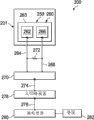
Mainly referring to Fig. 2, shown the system 200 for the treatment of patient's tissue site with it now.System 200 comprises applies part 201 and electron detection device 159.Electron detection device 159 can comprise first galvanic element 260.The first galvanic element 260 comprises first electrode 262 that is electrically connected on the first electrical lead 264.The first galvanic element 260 comprises second electrode 266 that is electrically connected on the second electrical lead 268.The first and second electrodes 262,266 can be connected on substrate 263 or the stabilized platform.Can be with the electricity usage device, for example, resistor 272 is connected electrically between the first electrical lead 264 and the second electrical lead 268.By monitoring unit 270, can measure the voltage between the electrical lead 264,268.When adjacent electrode 262,266 absorbed layer 115 become saturated, the voltage between the electrode 262,266 will rise and surpass threshold value.In schematic, a nonrestrictive embodiment, the longitudinal length of substrate 263 is 20mm, and width is 10mm, and these electrodes are that 8mm takes advantage of 8mm.
Analogue signal and signal that monitoring unit 270 can produce instructed voltage can be delivered on the analog-digital converter 276 by the 3rd lead-in wire 274.Then can digital signal be delivered on the microprocessor unit 280 by the 4th lead-in wire 278.Desirable signal can be monitored and handle to microprocessor unit 280.When the threshold value of determining to have reached, microprocessor unit 280 can provide signal to visual maybe can the listening of this alarm 282() or to another unit.
Present main reference Fig. 3-5 has presented another schematic embodiment of depressurized system 300 and deposited part 301.Depressurized system 300 comprises an electron detection device 359.Electron detection device 359 can comprise one or more galvanic circles, for example, and first galvanic circle 384, second galvanic circle 386 and the 3rd galvanic circle 388.Should be understood that, as said, " galvanic circle " be selective conductivity or only conduct electricity in the moment that circuit is finished.Be similar to the embodiment that had before presented, apply part 301 and can comprise the handle manifold 308 with the first side 310 and second side 312.Apply part 301 and comprise having the first side 317 and the second absorbed layer 315 towards patient's side 319.In another schematic embodiment, handle manifold 308 are got rid of by system 300, and the absorbed layer 315 of being placed by adjacent tissue position 304 second towards patient's side 319.
Shown in schematic embodiment in, handle manifold 308 is that place at adjacent tissue position 304.Tissue site is to extend through epidermis 303, passes corium 305 and enters wound 302 in the subcutaneous tissue 307.Containment member 311 is placed on the absorbed layer 315, and randomly on (if comprising) handle manifold 308, to form a seal cavity 354.Therefore, these galvanic circles 384,386,388 are disposed in containment member 311 times and contiguous absorbed layer 315.These galvanic circles 384,386,388 are in seal cavity 354.
Reduced pressure source 340 sealed members 311 cover, and provide decompression in sealing space 354.Containment member 311 comprises a hole 323, to allow this Reduced pressure source 340 aerofluxuss.Reduced pressure source 340 can be a Micropump, diaphragm pump, dish pump, piezoelectric pump or other pony pumps.In this schematic embodiment, Reduced pressure source is based upon applies in the part 301.Can comprise a layer 343, enter in this Reduced pressure source 340 to help distribute reduced pressure or prevention fluid.Should be understood that, can utilize other sources of decompression, and in other embodiments, these sources can be got rid of fully.Reduced pressure source 340 can be used connecting elements 341, so that these Reduced pressure source 340 fluids are connected to absorbed layer 315.In another embodiment, connecting elements 341 can extend through absorbed layer 315, and directly Reduced pressure source 340 is connected to handle manifold 308.
According to a schematic embodiment, in operation, as before, apply part 301 and receive exudate or other ion fluid from tissue site 304, and exudate is stored in this absorbed layer 315.Absorbed layer 315 can have a wicking layer, to help attraction from the exudate of handle manifold 308.When absorbed layer 315 becomes complete when saturated, absorbed layer 315 will no longer hold extra exudate.Therefore, when absorbed layer 315 was saturated, patient or health care supplier wanted to obtain alarm.These galvanic circles 384,386,388(have speaker or visual alarm or another warning devices) a such alarm is provided.
A plurality of galvanic circles 384,386 and 388 are added on the absorbed layer 315, thereby help provides the indication of the degree of filling of absorbed layer 315.The first galvanic circle 384 comprises a first terminal 385 and second terminal 387.By first electrical lead 389 first terminal 385 is connected to one and comprises a LED(light emitting diode) on the monitoring unit 370 of the 371, the 2nd LED373 and the 3rd LED375.By second electrical lead 397 the second terminal 387 is connected on the monitoring unit 370.
Fig. 4 A and 4B have shown and have represented other galvanic circles 386, the first galvanic circle 384 of 388.The first galvanic circle 384 comprises a conductive path 398 that is formed with one or more conductive gap 399.Conductive path 398 can be installed in the substrate 379.For helping to ensure that extreme prematurity is not given birth to signal, an electronic isolation layer (clearly not illustrating) can cover conductive path 398 and only have the hole at conductive gap 399 places.Will be appreciated that along with ion fluid around and cover conductive path 398, this ion fluid will be electrically connected conductive gap 399.In other words, this ion fluid connects as the electric bridge of conductive gap 399, and allows this conductive path 398 to carry electric current.When fully carrying electric current, monitoring unit 370 provides a signal, for example a LED371.Other galvanic circles 386, the 388th, similarly.Should be understood that, although shown three galvanic circles 384,386 and 388, can use any amount of galvanic circle.Can use the saturation of a plurality of galvanic circles to apply part 301 in different position assessments, and the rising scale of degree of filling is provided for applying part 301.
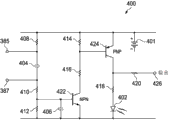
Present main reference Fig. 5, a schematic embodiment of having showed detection circuit 400.Can use numerous circuit design, and detection circuit 400 is the schematic embodiment of one of them.Detection circuit 400 can be included in the monitoring unit 370.Probe unit 400 can be configured to come the power supply to LED402 in response to the current flowing that passes first terminal 385 and this second terminal 387, along with by complete conduction or conductive path sensing, indicates the exudate that applies in the part 301.Detection circuit 400 can, for example, provide a galvanic circle, this galvanic circle is in response to by the startup due to the little electric current that passes between first terminal 385 and the second terminal 387, from battery 401 supply voltages to LED402.
The complete conductive path at first terminal 385 and the second terminal 387 two ends allows electric current to pass resistor 408 to walk around capacitor 404.Electric current passes the substrate that resistor 410 flows to NPN transistor 422, rather than the more high-resistance path that is provided by resistor 412 is provided.The electric current that enters the substrate of NPN transistor 422 has amplified the electric current that allows to pass resistor 414 and 416 inflow NPN transistors 422.When NPN transistor 422 was " opening ", substrate was with respect to the output of emitter stage, by drawing high by the input signal of resistor 410.
When the substrate that receives the electric current by resistor 414 was dragged down with respect to emitter stage, PNP transistor 424 was " opening ".As a result of, the current start PNP transistor 424 of the substrate by NPN transistor 422, thus be amplified to for the electric current of induced current to the current collector of this resistor 418 and LED402.As a result of, in response to the first terminal 385 of finishing a closed circuit or conductive path and the second terminal 387, NPN transistor 422 and PNP transistor 424 only are activated, thereby the electric current of LED402 is lighted in supply.
When the exudate in applying part was not enough to finish conductive path between terminal 385 and 387, detection circuit 400 cut out.From battery 401, blocked by capacitor 404 by the DC electric current of resistor 408.As a result of, no matter thereby be that NPN transistor 422 or PNP transistor 424 all are not activated for induced current to LED402.
In other embodiments, detection circuit 400 can be substituted by other current detection circuits.The resistance of detection circuit 400, electric capacity and other features may be based on the electricity needs of the sensitivity of the reading at first terminal 385 and the second terminal 387 two ends and LED402 and are changed.In another schematic embodiment, based on passing through the levels of current of resistor 418 to this indicator, LED402 can be replaced by visual or digital indicator, and amount or the type of the exudate in the part 301 applied in indication.This indicator can be element definitely calibrated simulation or numeral, thereby the feedback of that can listen, visual or sense of touch is provided to one or more users.
According to another schematic embodiment, capacitance sensor (senor) can be positioned to apply the outside of part, for example, be positioned on the sealing member 111 of electrode 162 tops shown in Fig. 1.Capacitance sensor has the sensing side (profile) of the position measurement electric capacity of in the end filling.When liquid arrived position to the inductive sensing side, as by the filling sensor finding, the electric capacity of the part of the deposited part that is associated with capacitance sensor changed in applying part.As a result of, this capacitance sensor produces an indication and applies the saturated signal of part.
According to another schematic embodiment, a kind of dyestuff can be placed in this absorbed layer (for example, absorbed layer 315), this provides the variation visual appearance (or optical characteristics) when becoming wet.The variation of variation, reflectance or other visual cues of the variation that this visual indication can be contrast, the variation of color, brightness.The variation of visual appearance can be for human eye or only for the perceptible variation of a device (for example, electronic light electric explorer).This electronic light electric explorer can be surveyed variation trickleer on the visual appearance.Contiguous sealing member 311 of this electronic light electric explorer and attached, and can survey the variation of contrast and produce the signal of this variation of indication on the optics.Therefore, along with absorbed layer 315 becomes saturated, dyestuff changes contrast, the variation of optical detector sensing contrast, and send and be full of signal.In another embodiment, dyestuff can be placed on handle manifold, for example, in the manifold 108.
According to another schematic embodiment still, the metal capacitance plate can be placed in the absorbed layer (for example, absorbed layer 315) or near, between a plurality of plates, have the interval of restriction.Along with ion fluid is filled interval between these plates, electric capacity changes.When ion fluid is filled interval between these plates, measure the variation of electric capacity and write down this variation.
Present main reference Fig. 6 has presented the sketch map of another schematic embodiment of reduced pressure treatment system 500.This reduced pressure treatment system 500 comprises that wound applies part 501, and this deposited part can comprise manifold 508 and an absorbed layer 515.Electron detection device 559 is associated with absorbed layer 515, and is configured to determine electronically when basically saturated this absorbed layer (or its some parts) is.Electron detection device 559 can be, for example, and a galvanic element or have the galvanic circle of conductive gap or determine electronically when saturated other instruments basically of this absorbed layer 515.
What be associated with this electron detection device 559 is radio communication and power subsystem 571.Radio communication and power subsystem 571 can provide electrical power to electron detection device 559, and can wireless receiving as by electron detection device 559 information that produce, that relate to the state of absorbed layer 515.Radio communication and power subsystem 571 can comprise radio communication and an electric power transfer unit 572 on base station 573, and antenna communication and processing unit 574.Radio communication and power subsystem 571 are similar to radio frequency identification device (RFID).Electric power is transferred to antenna communication and processing unit 574 by wireless signal 575 from radio communication and electric power transfer unit 572, provides electrical power to electron detection device 559 by adapter 576 from this antenna communication and processing unit.
Provide to the electric power of electron detection device 559 and can amplify the electric power (for example, passing through galvanic element) that has produced, or all electric power are provided, for example, be used for resistance circuit.In any case electron detection device 559 is configured to determine whether absorbed layer 515 is saturated, perhaps possibly, determines the absorbed layer 515 interior degree that have liquid, and is configured to produce the signal that carries relevant information.This signal can be delivered to antenna communication and processing unit 574 by adapter 576, and from this antenna communication and processing unit, wireless signal 575 carry informations are to radio communication and electric power transfer unit 572.By monitoring or control the other system of this reduced pressure treatment system 500, radio communication and electric power transfer unit 572 can further be processed for the signal that shows or use.Like this, use this embodiment, do not need direct electronics to connect between supervising device and the electron detection device 559.Therefore, the electric power that needs still less and strengthened comfort level.
The system 100,200,300,500 that presents allows to use electronic installation to determine the saturation of absorbed layer (for example, 115,215,315,515).Determine or the sense of touch inspection that this electronic signal can be used to user or the health care supplier gives the alarm or other signal owing to do not need vision: deposited part is saturated and should change.In addition, by arranging these parts, the middle of percent that can provide expression to be full of indicated.Should be understood that output signal also makes it possible in the analog or digital system, be easy to by interface access electronic controller or circuit.
In another schematic embodiment, the system and method that is used for the reception ion fluid can be similar to the system and method that had before presented, but this system does not utilize absorbed layer, and for example absorbed layer 115 can be omitted in reduced pressure treatment system 100.In such embodiment, these electrode fluids are connected on the part of applying part, this part will be exposed in the liquid, last liquid as accumulating in this deposited part.In another embodiment still, can use the deposited part without Fig. 1-4B of decompression, but can use from the wick material of this absorbed layer and can comprise extra wicking layer.In this embodiment, complete circuit will be indicated and be applied the saturated of part and send signal about required change.
According to one embodiment of the invention, the deposited part that is used for the reception ion fluid comprises an absorbed layer, and this absorbed layer is used for being communicated with this tissue site fluid and placing, and is used for receiving and keeping at least provisionally these ion fluid.This absorbed layer has first side and one second towards patient's side.Should apply part and further comprise a containment member that is used for covering this absorbed layer, and the first galvanic element that is associated with this absorbed layer, and be configured to when the absorbed layer near this first galvanic element when ion fluid is saturated basically generation voltage.This galvanic element typically comprises first electrode and second electrode, and this first electrode and the second electrode are communicated with a part of fluid of this absorbed layer, and this first electrode and the second electrode each interval; The first electrical lead and second electrical lead that is connected on this second electrode that is connected on this first electrode.This first electrode and the second electrode are configured to produce measurable electrical power when this ion fluid covers this first electrode and the second electrode.In one embodiment, this first electrode package cupric and this second electrode package are stanniferous.In one embodiment, this first electrode package cupric and this second electrode package are stanniferous, and wherein this ion fluid comprises exudate from the patient.In one embodiment, this first electrode package cupric and this second electrode comprise zinc.In one embodiment, this deposited part further comprises a plurality of galvanic elements that are associated with this absorbed layer, and this galvanic element is configured to provide with being saturated to ratio of absorbed layer of this deposited part electric power.Part be should apply and a radio communication and power subsystem may further include.
According to another embodiment, the system with reduced pressure treatment patient tissue site with it comprises: an absorbed layer, place for contiguous this tissue site; A containment member is used for covering this deposited part and a part of patient's epidermis to form a fluid-tight; A Reduced pressure source, this Reduced pressure source fluid is connected to this absorbed layer, and being used for provides decompression to this absorbed layer; A galvanic element that is associated with this absorbed layer, wherein this galvanic element is configured to produce electric power when ion fluid is saturated basically near the absorbed layer of this galvanic element; And a monitoring unit that is electrically connected to this galvanic element, be used for receiving the electric power from this galvanic element.This monitoring unit can be a comparator circuit or the analog-digital converter that is connected to microprocessor.In a rear embodiment, this microprocessor is configured to when this electric power reaches the electric power threshold value, sends an alarm signal.
According to another embodiment, the method for the treatment of tissue site comprises a deposited part, wherein should apply part and comprise: an absorbed layer is used for being communicated with this tissue site fluid and placing.This absorbed layer is used for receiving and keeping ion fluid.This absorbed layer has first side and one second towards patient's side.Should apply part and also comprise a containment member that is used for the first side of this absorbed layer of covering, and the first galvanic element that is associated with this absorbed layer, and be configured to when ion fluid is saturated basically near the absorbed layer of this first galvanic element, produce the voltage of indication full state.The method also comprises disposes this deposited part adjacent tissue position; This first galvanic element is electrically connected to a monitoring unit, and wherein this monitoring unit is configured to produce a deposited part and be full of signal when the voltage that receives from the indication full state of this first galvanic element; And provide to be decompressed to this deposited part, until this monitoring unit provides deposited part to be full of signal.Should apply part and may further include a plurality of galvanic elements that are associated with this absorbed layer, and this galvanic element is configured to provide with being saturated to ratio of absorbed layer of this deposited part voltage.
According to another embodiment, deposited part for the treatment of tissue site with it the patient comprises an absorbed layer, be used for being communicated with this tissue site fluid and placing, this absorbed layer is used for receiving and the reservation ion fluid, and this absorbed layer has first side and one second towards patient's side; A containment member is used for covering this absorbed layer; And galvanic circle that fluid is connected to this absorbed layer and has a first terminal, second terminal and at least one conductive gap, wherein adjust the size of this conductive gap and this conductive gap is configured to when covered by ion fluid, the generation electric bridge connects.
According to another embodiment, deposited part for the treatment of tissue site with it the patient comprises: an absorbed layer, be used for being communicated with this tissue site fluid and placing, this absorbed layer is used for receiving and the reservation fluid, and this absorbed layer has first side and one second towards patient's side; A kind of dyestuff that is associated with this absorbed layer, wherein this dyestuff is exercisable, thereby when becoming wet, changes optical characteristics; A containment member is for the first side that covers this absorbed layer; And one and this absorbed layer associated electrical optical pickocff, and be configured to when sensing this variation, survey variation and the generation signal of telecommunication of the optical characteristics of this dyestuff.
According to another embodiment, a deposited part that is used for receiving ion fluid, this deposited part comprises: a handle manifold is used for being communicated with this tissue site fluid and placing, and be used for to receive ion fluid, this handle manifold has first side and one second towards patient's side; A containment member is for the first side that covers this handle manifold; And first galvanic element that is associated with this handle manifold, and this first galvanic element is configured to produce voltage when ion fluid is saturated basically near the handle manifold of this first galvanic element.
According to another embodiment, (s) reduced pressure treatment system comprises: a handle manifold, and be used for being communicated with a tissue site fluid and placing, and be used for the reception ion fluid, this handle manifold has first side and one second towards patient's side; A containment member is for the first side that covers this handle manifold; An absorbed layer is arranged between sealing member and this handle manifold; An electron detection device that is associated with this absorbed layer is for generation of the signal of telecommunication of indicating at least complete saturation; And radio communication and power subsystem, comprise: an antenna that is associated with this electron detection device, communication and processing unit, and remote radio communication and power unit, this remote radio communication and power unit be configured to transferring electric power to this antenna, communicate by letter and processing unit and receive therefrom signal.
According to another embodiment, the deposited part for the treatment of tissue site comprises: a tissue applies the part member, is used near tissue positioned to be processed; And at least one liquid sensor, be used on the deposited part member of this tissue or among the existence of a position sensing liquid.The part member should be applied and a handle manifold can be comprised.The part member should be applied and an absorption component can be comprised.Should apply part and may further include a containment member that is used for covering the deposited part member of this tissue.This at least one liquid sensor can be a galvanic element.This at least one liquid sensor can be the selective conductivity loop; This loop can be the spaced conductive material of tool, and these intervals can bridge joint be finished this loop thus on the electricity by the ionic liquid on this surface, loop of contact.In one embodiment, the optical characteristics that this tissue applies the part member can be configured to change when liquid-absorbing, and wherein this sensor can be used to the optical pickocff of surveying this variation.This optical characteristics can be color.In this deposited part, can comprise a plurality of sensors.In an embodiment of this deposited part, at least one sensor is positioned in the surface that this tissue applies part.In one embodiment, at least one sensor is positioned in the deposited part of this tissue.This sensor can be positioned in this tissue of covering and apply outside the containment member of part member.A pump can be positioned at and apply within the part, to be used for applying decompression to this tissue site.
According to another embodiment, wound treatment system comprises the deposited part of describing in each according to the front and is electrically connected to supervising device on this at least one liquid sensor that this supervising device is configured to provide by this at least one liquid sensor the detection indication of liquid.
In general, provide for the system and method for sensing at the fluid of the deposited part on the patient and the generation signal of telecommunication.In a situation, galvanic element is used as the electron detection device.This galvanic element is placed in this deposited part and when applying part when basically saturated, produces voltage.In a situation, this deposited part is decompression, absorbs and apply part.Other system, method and deposited part have also been showed at this.
Although in the context of some schematic embodiment, disclosed the present invention and advantage thereof, should be understood that and to make different changes, replacement, conversion and change, and do not break away from the scope of the present invention that limits such as appending claims.
Should be understood that benefit described above and advantage can relate to an embodiment maybe can relate to some embodiments.Should further be understood that, mention " one/a kind of " element refer to one of these elements/a kind of or a plurality of/multiple.
The step of these methods described here can be undertaken by any suitable order, or carries out simultaneously in appropriate circumstances.
In suitable situation, the aspect of any above-described embodiment can be combined with the aspect of any described other embodiments, has comparable characteristic or different qualities and other examples that address same or different problems thereby form.For example, each sensor type (electrochemical sensor, conductive sensor, capacitance sensor) can be used with each pump type (apply the part outside, that apply part inside or do not use any pump).Different sensor types can be exercised usefulness with being combined into of any amount of required type.
Should be understood that the description of above-mentioned preferred embodiment only provides as an example, and can make various modifications by those skilled in the art.Above description, example and data provide the complete description of structure and the purposes of exemplary of the present invention.Although with certain the level of detail or with reference to one or more independent embodiments different embodiments of the present invention has been described, those skilled in the art can make many changes for disclosed embodiment, and do not depart from the scope of claims.
Claims (40)
1. deposited part that be used for to receive ion fluid, this deposited part comprises:
An absorbed layer is used for being communicated with this tissue site fluid and placing, and is used for receiving and also at least temporarily keeps ion fluid, and this absorbed layer has first side and one second towards patient's side;
A containment member is used for covering this absorbed layer;
First galvanic element, this galvanic element is associated with this absorbed layer, and is configured to produce voltage when ion fluid is saturated basically near the absorbed layer of this first galvanic element.
2. deposited part as claimed in claim 1, wherein this galvanic element comprises:
First electrode and second electrode, this first electrode and the second electrode are communicated with a part of fluid of this absorbed layer, and this first electrode and the second electrode each interval;
First electrical lead that is connected to this first electrode;
Second electrical lead that is connected to this second electrode; And
Wherein this first electrode and the second electrode are configured to produce measurable electrical power when this ion fluid covers this first electrode and the second electrode.
3. deposited part as claimed in claim 2, wherein this first electrode package cupric and this second electrode package are stanniferous.
4. deposited part as claimed in claim 2, wherein this first electrode package cupric and this second electrode package are stanniferous, and wherein this ion fluid comprises exudate from the patient.
5. deposited part as claimed in claim 2, wherein this first electrode package cupric and this second electrode comprise zinc.
6. such as each described deposited part in claim 1 or the above claim, further comprise a plurality of galvanic elements that are associated with this absorbed layer, and these galvanic elements are configured to provide with being saturated to ratio of absorbed layer of this deposited part electric power.
7. such as each described deposited part in claim 1 or the above claim, further comprise a radio communication and power subsystem.
8. system with reduced pressure treatment patient tissue site with it, this system comprises:
An absorbed layer is placed for contiguous this tissue site;
A containment member is used for covering this deposited part and a part of patient's epidermis to form a fluid-tight;
A fluid is connected to the Reduced pressure source of this absorbed layer, and being used for provides decompression to this absorbed layer;
A galvanic element that is associated with this absorbed layer, wherein this galvanic element is configured to produce electric power when ion fluid is saturated basically near the absorbed layer of this galvanic element; And
A monitoring unit that is electrically connected to this galvanic element is used for receiving the electric power from this galvanic element.
9. system as claimed in claim 8, wherein this monitoring unit is a comparator circuit.
10. system as claimed in claim 8, wherein this monitoring unit comprises an analog-digital converter that is connected to microprocessor, and wherein this microprocessor is configured to send an alarm signal when this electric power reaches the electric power threshold value.
11. such as each described deposited part among claim 8 or the claim 9-10, wherein this galvanic element comprises:
First electrode and second electrode, this first electrode and the second electrode are communicated with a part of fluid of this absorbed layer, and this first electrode and the second electrode each interval;
First electrical lead that is connected to this first electrode;
Second electrical lead that is connected to this second electrode; And
Wherein this first electrode and the second electrode are configured to produce measurable electrical power when this ion fluid covers this first electrode and the second electrode.
12. deposited part as claimed in claim 8, wherein this first electrode package cupric and this second electrode package are stanniferous.
13. deposited part as claimed in claim 8, wherein this first electrode package cupric and this second electrode package are stanniferous, and wherein this ion fluid comprises exudate from the patient.
14. deposited part as claimed in claim 8, wherein this first electrode package cupric and this second electrode comprise zinc.
15. such as each described deposited part among claim 8 or the claim 9-11, further comprise a plurality of galvanic elements that are associated with this absorbed layer, and these galvanic elements are configured to provide with being saturated to ratio of absorbed layer of this deposited part electric power.
16. such as each described deposited part among claim 8 or the claim 9-15, wherein this monitoring unit comprises an electron detection device and radio communication and power subsystem.
17. the method for the treatment of tissue site, the method comprises:
A deposited part is provided, wherein should applies part and comprise:
An absorbed layer is used for being communicated with this tissue site fluid and placing, and this absorbed layer is used for receiving and the reservation ion fluid, and this absorbed layer has first side and one second towards patient's side,
A containment member, for the first side that covers this absorbed layer, and
First galvanic element that is associated with this absorbed layer, and this galvanic element is configured to produce a voltage of indicating full state when ion fluid is saturated basically near the absorbed layer of this first galvanic element;
Should apply part adjacent tissue position and disposed;
This first galvanic element is electrically connected to a monitoring unit, and wherein this monitoring unit is configured to produce a deposited part and be full of signal when the voltage that receives from the indication full state of this first galvanic element; And
Provide to be decompressed to this deposited part, until this monitoring unit provides this deposited part to be full of signal.
18. deposited part as claimed in claim 17, wherein this galvanic element comprises:
First electrode and second electrode, this first electrode and the second electrode are communicated with a part of fluid of this absorbed layer, and this first electrode and the second electrode each interval;
First electrical lead that is connected to this first electrode;
Second electrical lead that is connected to this second electrode; And
Wherein this first electrode and the second electrode are configured to produce measurable electrical power when this ion fluid covers this first electrode and the second electrode.
19. method as claimed in claim 17, wherein this first electrode package cupric and this second electrode package are stanniferous.
20. method as claimed in claim 17, wherein this first electrode package cupric and this second electrode package are stanniferous, and wherein this ion fluid comprises exudate from the patient.
21. method as claimed in claim 17, wherein this first electrode package cupric and this second electrode comprise zinc.
22. such as each described method among claim 17 or the claim 18-21, wherein should apply part and further comprise a plurality of galvanic elements that are associated with this absorbed layer, and these galvanic elements are configured to provide with being saturated to ratio of absorbed layer of this deposited part voltage.
23. the deposited part for the treatment of patient's tissue site with it, this deposited part comprises:
An absorbed layer is used for being communicated with this tissue site fluid and placing, and this absorbed layer is used for receiving and the reservation ion fluid, and this absorbed layer has first side and one second towards patient's side;
A containment member is used for covering this absorbed layer; And
A fluid is connected to this absorbed layer and has a first terminal, the galvanic circle of second terminal and at least one conductive gap, wherein adjust the size of this conductive gap and this conductive gap is configured to when covered by ion fluid, the generation electric bridge connects.
24. the deposited part for the treatment of patient's tissue site with it, this deposited part comprises:
An absorbed layer is used for being communicated with this tissue site fluid and placing, and this absorbed layer is used for receiving and the reservation ion fluid, and this absorbed layer has first side and one second towards patient's side;
A kind of dyestuff that is associated with this absorbed layer, wherein this dyestuff is exercisable, thereby when becoming wet, changes optical characteristics;
A containment member is for the first side that covers this absorbed layer; And
Electrooptics sensor that is associated with this absorbed layer, and this sensor is configured to when sensing this variation, survey this dyestuff optical characteristics variation and produce the signal of telecommunication.
25. a deposited part that is used for receiving ion fluid, this deposited part comprises:
A handle manifold is used for being communicated with this tissue site fluid and placing, and is used for the reception ion fluid, and this handle manifold has first side and one second towards patient's side;
A containment member is for the first side that covers this handle manifold;
First galvanic element that is associated with this handle manifold, and this galvanic element is configured to produce voltage when ion fluid is saturated basically near the handle manifold of this first galvanic element.
26. a reduced pressure treatment system comprises:
A handle manifold is used for being communicated with the tissue site fluid and placing, and is used for the reception ion fluid, and this handle manifold has first side and one second towards patient's side;
A containment member is for the first side that covers this handle manifold;
An absorbed layer is arranged between sealing member and this handle manifold;
An electron detection device that is associated with this absorbed layer is for generation of the signal of telecommunication of indicating at least complete saturation; And
Radio communication and power subsystem comprise:
An antenna that is associated with this electron detection device, communication and processing unit, and
Remote radio communication and power unit, this unit is configured to transferring electric power to this antenna, communication and processing unit and receives therefrom signal.
27. the deposited part for the treatment of tissue site, this deposited part comprises:
A tissue applies the part member, is used near tissue positioned to be processed; And
At least one liquid sensor, be used on the deposited part member of this tissue or among the existence of a position sensing liquid.
28. a deposited part according to claim 27 wherein should apply the part member and comprise a handle manifold.
29. one according to claim 27 or 28 described deposited parts, wherein should apply part member and comprise an absorption component.
30. each described deposited part in 29 according to claim 27 further comprises a containment member, the sealing member is used for covering the deposited part member of this tissue.
31. each described deposited part in 30 according to claim 27, wherein this at least one liquid sensor is galvanic element.
32. each described deposited part in 30 according to claim 27, wherein this at least one liquid sensor is the selective conductivity loop, this loop comprises the spaced conductive material of tool, these intervals can bridge joint be finished this loop thus on the electricity by the ionic liquid on this surface, loop of contact.
33. each described deposited part in 30 according to claim 27, wherein this tissue optical characteristics of applying the part member is configured to change when liquid-absorbing, and wherein this sensor is be used to the optical pickocff of surveying this variation.
34. a deposited part according to claim 33, wherein this optical characteristics is color.
35. each described deposited part in 34 according to claim 27 comprises a plurality of sensors.
36. each described deposited part in 35 according to claim 27, wherein this at least one sensor is positioned on the surface that this tissue applies part.
37. each described deposited part in 35 according to claim 27, wherein this at least one sensor is positioned in this tissue and applies in the part.
38. one according to claim 33 or 34 described deposited parts, wherein this sensor is positioned in outside the containment member, and the sealing member is used for covering the deposited part member of this tissue.
39. each described deposited part in 35 according to claim 27 further comprises a pump, this pump is located with this deposited part, to be used for applying decompression to this tissue site.
40. a wound treatment system comprises:
Each described deposited part in 39 according to claim 27; And
One is electrically connected to supervising device on this at least one fluid sensor, and this supervising device is configured to provide by this at least one liquid sensor the detection indication of liquid.
Applications Claiming Priority (7)
| Application Number | Priority Date | Filing Date | Title |
|---|---|---|---|
| US36561410P | 2010-07-19 | 2010-07-19 | |
| US61/365,614 | 2010-07-19 | ||
| US40719410P | 2010-10-27 | 2010-10-27 | |
| US61/407,194 | 2010-10-27 | ||
| US41873010P | 2010-12-01 | 2010-12-01 | |
| US61/418,730 | 2010-12-01 | ||
| PCT/US2011/044182 WO2012012286A1 (en) | 2010-07-19 | 2011-07-15 | Systems and methods for electrically detecting the presence of exudate in dressings |
Publications (1)
| Publication Number | Publication Date |
|---|---|
| CN102970949A true CN102970949A (en) | 2013-03-13 |
Family
ID=44514139
Family Applications (2)
| Application Number | Title | Priority Date | Filing Date |
|---|---|---|---|
| CN2011800330928A Pending CN102970949A (en) | 2010-07-19 | 2011-07-15 | Systems and methods for electrically detecting the presence of exudate in dressings |
| CN201180033093.2A Expired - Fee Related CN102970950B (en) | 2010-07-19 | 2011-07-15 | Inflatable removal wound applies part assembly, system and method |
Family Applications After (1)
| Application Number | Title | Priority Date | Filing Date |
|---|---|---|---|
| CN201180033093.2A Expired - Fee Related CN102970950B (en) | 2010-07-19 | 2011-07-15 | Inflatable removal wound applies part assembly, system and method |
Country Status (8)
| Country | Link |
|---|---|
| US (6) | US8795257B2 (en) |
| EP (4) | EP2826449B1 (en) |
| JP (3) | JP6258700B2 (en) |
| CN (2) | CN102970949A (en) |
| AU (2) | AU2011279913B2 (en) |
| CA (2) | CA2805049C (en) |
| TW (2) | TW201216930A (en) |
| WO (2) | WO2012012288A1 (en) |
Families Citing this family (162)
| Publication number | Priority date | Publication date | Assignee | Title |
|---|---|---|---|---|
| CN102715984B (en) | 2005-09-06 | 2014-07-09 | 施乐辉股份有限公司 | Self contained wound dressing with micropump |
| US8398603B2 (en) | 2006-02-28 | 2013-03-19 | Coloplast A/S | Leak sensor |
| EP1905465B2 (en) | 2006-09-28 | 2013-11-27 | Smith & Nephew, Inc. | Portable wound therapy system |
| GB2455962A (en) | 2007-12-24 | 2009-07-01 | Ethicon Inc | Reinforced adhesive backing sheet, for plaster |
| CN101959479B (en) | 2008-03-05 | 2014-08-20 | 凯希特许有限公司 | Dressing and method for applying reduced pressure to and collecting and storing fluid from a tissue site |
| GB0808376D0 (en) | 2008-05-08 | 2008-06-18 | Bristol Myers Squibb Co | Wound dressing |
| GB0817796D0 (en) | 2008-09-29 | 2008-11-05 | Convatec Inc | wound dressing |
| US20110054420A1 (en) * | 2009-08-27 | 2011-03-03 | Christopher Brian Locke | Reduced-pressure wound dressings and systems for re-epithelialization and granulation |
| US8690844B2 (en) * | 2009-08-27 | 2014-04-08 | Kci Licensing, Inc. | Re-epithelialization wound dressings and systems |
| US8814842B2 (en) | 2010-03-16 | 2014-08-26 | Kci Licensing, Inc. | Delivery-and-fluid-storage bridges for use with reduced-pressure systems |
| US8604265B2 (en) | 2010-04-16 | 2013-12-10 | Kci Licensing, Inc. | Dressings and methods for treating a tissue site on a patient |
| US8795257B2 (en) * | 2010-07-19 | 2014-08-05 | Kci Licensing, Inc. | Systems and methods for electrically detecting the presence of exudate in dressings |
| GB201020236D0 (en) | 2010-11-30 | 2011-01-12 | Convatec Technologies Inc | A composition for detecting biofilms on viable tissues |
| JP5965409B2 (en) | 2010-12-08 | 2016-08-03 | コンバテック・テクノロジーズ・インコーポレイテッドConvatec Technologies Inc | Integrated system for assessing wound exudate |
| JP6151186B2 (en) | 2010-12-08 | 2017-06-21 | コンバテック・テクノロジーズ・インコーポレイテッドConvatec Technologies Inc | Wound exudate system attachment device |
| GB2488749A (en) | 2011-01-31 | 2012-09-12 | Systagenix Wound Man Ip Co Bv | Laminated silicone coated wound dressing |
| US9421132B2 (en) | 2011-02-04 | 2016-08-23 | University Of Massachusetts | Negative pressure wound closure device |
| EP3932327A1 (en) | 2011-02-04 | 2022-01-05 | University Of Massachusetts | Negative pressure wound closure device |
| WO2012142002A1 (en) * | 2011-04-12 | 2012-10-18 | Kci Licensing, Inc. | Evaporative fluid pouch and systems for use with body fluids |
| GB201106491D0 (en) | 2011-04-15 | 2011-06-01 | Systagenix Wound Man Ip Co Bv | Patterened silicone coating |
| JP6224581B2 (en) | 2011-06-24 | 2017-11-01 | ケーシーアイ ライセンシング インコーポレイテッド | Reduced pressure dressing with tissue fixation elements |
| HUE045003T2 (en) | 2011-07-14 | 2019-11-28 | Smith & Nephew | Wound dressing and method of treatment |
| JP6158804B2 (en) * | 2011-07-20 | 2017-07-05 | イーテクト,インコーポレイテッド | Wet sensor, wetness monitoring system, and related methods |
| GB201115182D0 (en) | 2011-09-02 | 2011-10-19 | Trio Healthcare Ltd | Skin contact material |
| GB2497406A (en) | 2011-11-29 | 2013-06-12 | Webtec Converting Llc | Dressing with a perforated binder layer |
| GB201120693D0 (en) | 2011-12-01 | 2012-01-11 | Convatec Technologies Inc | Wound dressing for use in vacuum therapy |
| EP3005997B1 (en) | 2011-12-16 | 2024-06-26 | Solventum Intellectual Properties Company | Releasable medical drapes |
| US10940047B2 (en) | 2011-12-16 | 2021-03-09 | Kci Licensing, Inc. | Sealing systems and methods employing a hybrid switchable drape |
| DE102012201390B4 (en) * | 2012-01-24 | 2017-03-30 | Fraunhofer-Gesellschaft zur Förderung der angewandten Forschung e.V. | Sensor arrangement for a vacuum therapy system and vacuum therapy system with sensor functionality |
| FR2986151B1 (en) * | 2012-01-30 | 2014-03-14 | Commissariat Energie Atomique | DRESSING HAVING A DETECTION SYSTEM. |
| AU2013234034B2 (en) | 2012-03-12 | 2017-03-30 | Smith & Nephew Plc | Reduced pressure apparatus and methods |
| US10226212B2 (en) | 2012-04-12 | 2019-03-12 | Elwha Llc | Appurtenances to cavity wound dressings |
| US10158928B2 (en) * | 2012-04-12 | 2018-12-18 | Elwha Llc | Appurtenances for reporting information regarding wound dressings |
| US10130518B2 (en) * | 2012-04-12 | 2018-11-20 | Elwha Llc | Appurtenances including sensors for reporting information regarding wound dressings |
| US10265219B2 (en) * | 2012-04-12 | 2019-04-23 | Elwha Llc | Wound dressing monitoring systems including appurtenances for wound dressings |
| US9427505B2 (en) * | 2012-05-15 | 2016-08-30 | Smith & Nephew Plc | Negative pressure wound therapy apparatus |
| US10117782B2 (en) | 2012-05-24 | 2018-11-06 | Smith & Nephew, Inc. | Devices and methods for treating and closing wounds with negative pressure |
| RU2015104581A (en) | 2012-07-16 | 2016-09-10 | Смит Энд Нефью, Инк. | DEVICE FOR CLOSING THE Wound USING NEGATIVE PRESSURE |
| GB201216928D0 (en) | 2012-09-21 | 2012-11-07 | I2R Medical Ltd | Portable medical device system |
| EP3669842B1 (en) | 2012-11-16 | 2023-09-27 | 3M Innovative Properties Company | Medical drape with pattern adhesive layers |
| GB201222770D0 (en) | 2012-12-18 | 2013-01-30 | Systagenix Wound Man Ip Co Bv | Wound dressing with adhesive margin |
| CA2895896A1 (en) | 2012-12-20 | 2014-06-26 | Convatec Technologies Inc. | Processing of chemically modified cellulosic fibres |
| GB201317746D0 (en) | 2013-10-08 | 2013-11-20 | Smith & Nephew | PH indicator |
| GB201300470D0 (en) * | 2013-01-11 | 2013-02-27 | Smith & Nephew | Moisture indicator dressing |
| CA2900771C (en) * | 2013-02-12 | 2020-02-18 | Electrochemical Oxygen Concepts, Inc. | Dressing for wound treatment |
| CA2902776C (en) | 2013-03-13 | 2023-03-07 | Smith & Nephew Inc. | Wound treatment apparatus and use thereof |
| US9737649B2 (en) | 2013-03-14 | 2017-08-22 | Smith & Nephew, Inc. | Systems and methods for applying reduced pressure therapy |
| US10159771B2 (en) | 2013-03-14 | 2018-12-25 | Smith & Nephew Plc | Compressible wound fillers and systems and methods of use in treating wounds with negative pressure |
| CN110141689A (en) * | 2013-03-14 | 2019-08-20 | 史密夫和内修有限公司 | System and method for application decompression treatment |
| US10238547B2 (en) * | 2013-06-04 | 2019-03-26 | Gui Global Products, Ltd. | Prophylactic dressing and use of same in the prevention of infection |
| RU2016104132A (en) | 2013-07-16 | 2017-08-21 | СМИТ ЭНД НЕФЬЮ ПиЭлСи | DEVICE FOR TREATMENT OF THE RAS |
| WO2015065742A1 (en) | 2013-10-28 | 2015-05-07 | Kci Licensing, Inc. | Hybrid sealing tape |
| US9956120B2 (en) | 2013-10-30 | 2018-05-01 | Kci Licensing, Inc. | Dressing with sealing and retention interface |
| EP3656362A1 (en) | 2013-10-30 | 2020-05-27 | KCI Licensing, Inc. | Condensate absorbing and dissipating system related application |
| EP3062833B1 (en) | 2013-10-30 | 2019-04-17 | KCI Licensing, Inc. | Absorbent conduit and system |
| EP3821859A1 (en) * | 2013-10-30 | 2021-05-19 | 3M Innovative Properties Co. | Dressing with differentially sized perforations |
| EP3488880B1 (en) * | 2014-01-30 | 2020-07-01 | Murata Manufacturing Co., Ltd. | Suction device |
| WO2015130471A1 (en) | 2014-02-28 | 2015-09-03 | Kci Licensing, Inc. | Hybrid drape having a gel-coated perforated mesh |
| US11026844B2 (en) * | 2014-03-03 | 2021-06-08 | Kci Licensing, Inc. | Low profile flexible pressure transmission conduit |
| US10531977B2 (en) | 2014-04-17 | 2020-01-14 | Coloplast A/S | Thermoresponsive skin barrier appliances |
| US10406266B2 (en) | 2014-05-02 | 2019-09-10 | Kci Licensing, Inc. | Fluid storage devices, systems, and methods |
| CN106535842B (en) | 2014-06-05 | 2020-07-17 | 凯希特许有限公司 | Dressing with fluid acquisition and distribution features |
| WO2016006457A1 (en) * | 2014-07-07 | 2016-01-14 | 株式会社村田製作所 | Negative-pressure closure therapy device |
| CA2954467A1 (en) | 2014-07-10 | 2016-01-28 | Smith & Nephew Plc | Improvements in and relating to devices |
| US10583042B2 (en) * | 2014-08-08 | 2020-03-10 | Neogenix, Llc | Wound care devices, apparatus, and treatment methods |
| CN104146822A (en) * | 2014-09-01 | 2014-11-19 | 左衍海 | Wound surface covering device convenient to seal for vacuum sealing drainage |
| WO2016073419A1 (en) * | 2014-11-03 | 2016-05-12 | Fistula Solution Corporation | Containment devices for treatment of intestinal fistulas and complex wounds |
| US11426302B2 (en) * | 2014-11-03 | 2022-08-30 | Fistula Solution Corporation | Containment devices for treatment of intestinal fistulas and complex wounds |
| EP3034054B1 (en) | 2014-12-16 | 2021-01-20 | Absorbest AB | Wound dressing with a sensor and method for manufacturing the same |
| WO2016100098A1 (en) | 2014-12-17 | 2016-06-23 | Kci Licensing, Inc. | Dressing with offloading capability |
| AU2015370586B2 (en) | 2014-12-22 | 2020-07-16 | Smith & Nephew Plc | Negative pressure wound therapy apparatus and methods |
| US10828403B2 (en) | 2014-12-29 | 2020-11-10 | Smith & Nephew Plc | Negative pressure wound therapy apparatus and methods for operating the apparatus |
| JP7042084B2 (en) * | 2015-02-17 | 2022-03-25 | 帝人ファーマ株式会社 | Medical pump filtration device, its manufacturing method and usage method |
| FR3033554B1 (en) | 2015-03-09 | 2020-01-31 | Centre National De La Recherche Scientifique | PROCESS FOR FORMING A GRAPHENE DEVICE |
| EP3067073A1 (en) | 2015-03-09 | 2016-09-14 | Centre National De La Recherche Scientifique | Method of forming a medical device comprising graphene |
| US12059560B2 (en) | 2015-03-09 | 2024-08-13 | Centre National De La Recherche Scientifique | Method of forming a device comprising graphene |
| ES2769811T3 (en) * | 2015-04-27 | 2020-06-29 | Smith & Nephew | Reduced pressure devices |
| AU2016254119A1 (en) | 2015-04-29 | 2017-10-05 | Smith & Nephew Inc. | Negative pressure wound closure device |
| US11246975B2 (en) | 2015-05-08 | 2022-02-15 | Kci Licensing, Inc. | Low acuity dressing with integral pump |
| US10478349B2 (en) * | 2015-08-28 | 2019-11-19 | Sentine, Inc. | Body fluid sensor pad |
| EP3741335B1 (en) | 2015-09-01 | 2023-05-24 | KCI Licensing, Inc. | Dressing with increased apposition force |
| WO2017048866A1 (en) | 2015-09-17 | 2017-03-23 | Kci Licensing, Inc. | Hybrid silicone and acrylic adhesive cover for use with wound treatment |
| US10575991B2 (en) | 2015-12-15 | 2020-03-03 | University Of Massachusetts | Negative pressure wound closure devices and methods |
| US10814049B2 (en) | 2015-12-15 | 2020-10-27 | University Of Massachusetts | Negative pressure wound closure devices and methods |
| GB201600747D0 (en) | 2016-01-14 | 2016-03-02 | Smith & Nephew | Improvements in and relating to devices |
| GB201600746D0 (en) | 2016-01-14 | 2016-03-02 | Smith & Nephew | Improvements in and relating to polymer materials |
| CN114053031A (en) * | 2016-03-07 | 2022-02-18 | 史密夫及内修公开有限公司 | Wound therapy apparatus and method utilizing a negative pressure source integrated into a wound dressing |
| EP3435941B1 (en) | 2016-03-30 | 2021-09-01 | ConvaTec Technologies Inc. | Detecting microbial infections in wounds |
| BR112018070238A2 (en) | 2016-03-30 | 2019-01-29 | Acib Gmbh | detection of microbial wound infection |
| US11285047B2 (en) | 2016-04-26 | 2022-03-29 | Smith & Nephew Plc | Wound dressings and methods of use with integrated negative pressure source having a fluid ingress inhibition component |
| CA3038206A1 (en) | 2016-05-03 | 2017-11-09 | Smith & Nephew Plc | Optimizing power transfer to negative pressure sources in negative pressure therapy systems |
| US11096831B2 (en) | 2016-05-03 | 2021-08-24 | Smith & Nephew Plc | Negative pressure wound therapy device activation and control |
| US11305047B2 (en) | 2016-05-03 | 2022-04-19 | Smith & Nephew Plc | Systems and methods for driving negative pressure sources in negative pressure therapy systems |
| GB201608099D0 (en) | 2016-05-09 | 2016-06-22 | Convatec Technologies Inc | Negative pressure wound dressing |
| ES2912094T3 (en) | 2016-07-08 | 2022-05-24 | Convatec Technologies Inc | Fluid flow detection |
| KR20190028467A (en) | 2016-07-08 | 2019-03-18 | 컨바텍 테크놀러지스 인크 | Body fluid collecting device |
| KR20190026858A (en) | 2016-07-08 | 2019-03-13 | 컨바텍 테크놀러지스 인크 | Flexible negative pressure system |
| EP3487547A1 (en) * | 2016-07-21 | 2019-05-29 | KCI Licensing, Inc. | Portable negative-pressure wound closure system |
| AU2017315129B2 (en) | 2016-08-25 | 2022-10-27 | Smith & Nephew Plc | Absorbent negative pressure wound therapy dressing |
| JP7063887B2 (en) | 2016-09-29 | 2022-05-09 | スミス アンド ネフュー インコーポレイテッド | Construction and protection of components in negative pressure wound healing systems |
| JP7055795B2 (en) | 2016-09-30 | 2022-04-18 | スミス アンド ネフュー ピーエルシー | Negative pressure wound healing equipment and methods with integrated electronic devices |
| GB2555584B (en) | 2016-10-28 | 2020-05-27 | Smith & Nephew | Multi-layered wound dressing and method of manufacture |
| WO2018108724A1 (en) | 2016-12-12 | 2018-06-21 | Smith & Nephew Plc | Pressure wound therapy status indication via external device |
| WO2018156730A1 (en) | 2017-02-22 | 2018-08-30 | Cornell University | Mechanical vacuum dressing for mechanically managing, protecting and suctioning small incisional wounds |
| EP3592313B1 (en) | 2017-03-07 | 2021-07-07 | Smith & Nephew, Inc | Reduced pressure therapy systems and methods including an antenna |
| CA3055664A1 (en) | 2017-03-08 | 2018-09-13 | Smith & Nephew Plc | Negative pressure wound therapy device control in presence of fault condition |
| CN110612131B (en) | 2017-05-09 | 2023-05-16 | 史密夫及内修公开有限公司 | Redundant control for negative pressure wound therapy system |
| US10751212B2 (en) * | 2017-06-26 | 2020-08-25 | Maryam Raza | Multilayer dressing device and method for preventing and treating pressure ulcers and chronic wounds |
| RU175660U1 (en) * | 2017-07-25 | 2017-12-13 | Федеральное государственное бюджетное образовательное учреждение высшего образования "Амурская государственная медицинская академия" Министерства здравоохранения Российской Федерации | Device for recording the appearance of exudate in a postoperative wound |
| AU2018331954B2 (en) | 2017-09-13 | 2024-07-04 | Smith & Nephew Plc | Negative pressure wound treatment apparatuses and methods with integrated electronics |
| GB201718070D0 (en) | 2017-11-01 | 2017-12-13 | Smith & Nephew | Negative pressure wound treatment apparatuses and methods with integrated electronics |
| WO2019086332A1 (en) | 2017-11-01 | 2019-05-09 | Smith & Nephew Plc | Negative pressure wound treatment apparatuses and methods with integrated electronics |
| GB201718054D0 (en) | 2017-11-01 | 2017-12-13 | Smith & Nephew | Sterilization of integrated negative pressure wound treatment apparatuses and sterilization methods |
| GB201718072D0 (en) | 2017-11-01 | 2017-12-13 | Smith & Nephew | Negative pressure wound treatment apparatuses and methods with integrated electronics |
| US11839527B2 (en) | 2017-12-06 | 2023-12-12 | Cornell University | Manually-operated negative pressure wound therapy (NPWT) bandage with improved pump efficiency, automatic pressure indicator and automatic pressure limiter |
| JP2019113917A (en) * | 2017-12-21 | 2019-07-11 | ルネサスエレクトロニクス株式会社 | Data processing device, and control method of data processing device |
| JP7348184B2 (en) | 2017-12-22 | 2023-09-20 | コロプラスト アクティーゼルスカブ | Hinged joint for ostomy base plate and sensor assembly parts |
| US10849781B2 (en) | 2017-12-22 | 2020-12-01 | Coloplast A/S | Base plate for an ostomy appliance |
| US11607334B2 (en) | 2017-12-22 | 2023-03-21 | Coloplast A/S | Base plate for a medical appliance, a monitor device and a system for a medical appliance |
| WO2019120435A1 (en) | 2017-12-22 | 2019-06-27 | Coloplast A/S | Ostomy appliance with selective sensor points and related methods |
| WO2019120443A1 (en) | 2017-12-22 | 2019-06-27 | Coloplast A/S | Sensor assembly part and a base plate for an ostomy appliance and a method for manufacturing a base plate or a sensor assembly part |
| JP7282781B2 (en) | 2017-12-22 | 2023-05-29 | コロプラスト アクティーゼルスカブ | Ostomy appliance with angular range leak detection |
| US11865029B2 (en) | 2017-12-22 | 2024-01-09 | Coloplast A/S | Monitor device of a medical system having a connector for coupling to both a base plate and an accessory device |
| US11559423B2 (en) | 2017-12-22 | 2023-01-24 | Coloplast A/S | Medical appliance system, monitor device, and method of monitoring a medical appliance |
| CN111432756B (en) | 2017-12-22 | 2022-07-29 | 科洛普拉斯特公司 | Base plate and sensor assembly part of an ostomy system with a leak sensor |
| US10799385B2 (en) | 2017-12-22 | 2020-10-13 | Coloplast A/S | Ostomy appliance with layered base plate |
| US11628084B2 (en) | 2017-12-22 | 2023-04-18 | Coloplast A/S | Sensor assembly part and a base plate for a medical appliance and a device for connecting to a base plate or a sensor assembly part |
| WO2019120429A1 (en) | 2017-12-22 | 2019-06-27 | Coloplast A/S | Data collection schemes for an ostomy appliance and related methods |
| JP2021508269A (en) | 2017-12-22 | 2021-03-04 | コロプラスト アクティーゼルスカブ | A method for manufacturing a base plate for an ostomy orthosis and a sensor assembly part for the base plate, and a base plate and a sensor assembly part. |
| LT3727219T (en) | 2017-12-22 | 2023-09-11 | Coloplast A/S | Moisture detecting base plate for an ostomy appliance and a system for determining moisture propagation in a base plate and/or a sensor assembly part |
| US10500084B2 (en) | 2017-12-22 | 2019-12-10 | Coloplast A/S | Accessory devices of an ostomy system, and related methods for communicating leakage state |
| US12064369B2 (en) | 2017-12-22 | 2024-08-20 | Coloplast A/S | Processing schemes for an ostomy system, monitor device for an ostomy appliance and related methods |
| WO2019120449A1 (en) | 2017-12-22 | 2019-06-27 | Coloplast A/S | Ostomy system and monitor device with angular leakage detection |
| EP3727246B1 (en) | 2017-12-22 | 2024-07-10 | Coloplast A/S | Tools and methods for cutting holes in an ostomy appliance |
| US11534323B2 (en) | 2017-12-22 | 2022-12-27 | Coloplast A/S | Tools and methods for placing a medical appliance on a user |
| US11590015B2 (en) | 2017-12-22 | 2023-02-28 | Coloplast A/S | Sensor assembly part and a base plate for a medical appliance and a method for manufacturing a sensor assembly part and a base plate |
| EP3729453A1 (en) | 2017-12-22 | 2020-10-28 | Coloplast A/S | Calibration methods for ostomy appliance tools |
| US11612508B2 (en) | 2017-12-22 | 2023-03-28 | Coloplast A/S | Sensor assembly part for a medical appliance and a method for manufacturing a sensor assembly part |
| EP3729456B1 (en) | 2017-12-22 | 2021-12-01 | Coloplast A/S | Monitor device of an ostomy system and associated method for operating a monitor device |
| US11754063B2 (en) * | 2018-01-02 | 2023-09-12 | Kci Licensing, Inc. | Negative pressure wound therapy device with silent piezoelectric pump |
| EP3517086A1 (en) | 2018-01-30 | 2019-07-31 | Absorbest AB | Absorbent body |
| EP3755282B1 (en) | 2018-02-20 | 2024-05-08 | Coloplast A/S | Sensor assembly part and a base plate for an ostomy appliance and a device for connecting to a base plate and/or a sensor assembly part |
| WO2019161863A1 (en) | 2018-02-20 | 2019-08-29 | Coloplast A/S | Accessory devices of an ostomy system, and related methods for changing an ostomy appliance based on future operating state |
| WO2019174697A1 (en) | 2018-03-15 | 2019-09-19 | Coloplast A/S | Apparatus and methods for navigating ostomy appliance user to changing room |
| WO2019199986A1 (en) * | 2018-04-11 | 2019-10-17 | Neogenix, Llc | Wound care devices, apparatus, and treatment methods |
| WO2019200035A1 (en) * | 2018-04-13 | 2019-10-17 | Kci Licensing, Inc. | Npwt system with selectively controllable airflow |
| USD898925S1 (en) | 2018-09-13 | 2020-10-13 | Smith & Nephew Plc | Medical dressing |
| WO2020124038A1 (en) | 2018-12-13 | 2020-06-18 | University Of Massachusetts | Negative pressure wound closure devices and methods |
| WO2020125907A1 (en) | 2018-12-20 | 2020-06-25 | Coloplast A/S | Ostomy condition classification with image data transformation, devices and related methods |
| US11517469B2 (en) | 2019-01-31 | 2022-12-06 | Coloplast A/S | Base plate and sensor assembly part of an ostomy system having a moisture sensor |
| US11612512B2 (en) | 2019-01-31 | 2023-03-28 | Coloplast A/S | Moisture detecting base plate for an ostomy appliance and a system for determining moisture propagation in a base plate and/or a sensor assembly part |
| US11207097B2 (en) | 2019-02-13 | 2021-12-28 | Andrew Thomas Obst | Fluid management device for medical tubes and drainage incisions |
| GB201903774D0 (en) | 2019-03-20 | 2019-05-01 | Smith & Nephew | Negative pressure wound treatment apparatuses and methods with integrated electronics |
| KR102238777B1 (en) * | 2019-04-02 | 2021-04-09 | 한국광기술원 | Wearable wound treatment device |
| GB201907716D0 (en) | 2019-05-31 | 2019-07-17 | Smith & Nephew | Systems and methods for extending operational time of negative pressure wound treatment apparatuses |
| JP7511585B2 (en) | 2019-06-03 | 2024-07-05 | コンバテック リミティド | Methods and devices for destroying and containing pathogens - Patents.com |
| US11523932B2 (en) | 2019-06-26 | 2022-12-13 | Andrew Thomas Obst | Enteric fistula, rectovaginal fistula, and ostomy effluent containment system, and devices and methods thereof |
| WO2021059192A1 (en) * | 2019-09-25 | 2021-04-01 | Kci Licensing, Inc. | Medical fluid pump with audible alarms |
| US11771819B2 (en) | 2019-12-27 | 2023-10-03 | Convatec Limited | Low profile filter devices suitable for use in negative pressure wound therapy systems |
| US11331221B2 (en) | 2019-12-27 | 2022-05-17 | Convatec Limited | Negative pressure wound dressing |
| AU2021223085A1 (en) * | 2020-02-20 | 2022-08-25 | Convatec Limited | A wound dressing and a wound therapy apparatus |
| USD970017S1 (en) | 2020-08-25 | 2022-11-15 | Coloplast A/S | Ostomy appliance monitor |
Citations (6)
| Publication number | Priority date | Publication date | Assignee | Title |
|---|---|---|---|---|
| DE4014572A1 (en) * | 1990-05-07 | 1991-11-14 | Alexander Staeblein | Medical monitoring sensor for bleeding under bandage - responds to change in bandaging material i.e. dampness and/or colour to release alarm via evaluating circuit |
| WO2005099644A2 (en) * | 2004-04-16 | 2005-10-27 | University Of Strathclyde | Wound dressings and performance measurement of such dressings |
| US20080041401A1 (en) * | 2006-08-15 | 2008-02-21 | Casola Robert P | Computer adjusted pressure wound care devices, systems & methods |
| WO2009093116A1 (en) * | 2008-01-25 | 2009-07-30 | The University Of Cape Town | Wound dressing system and method |
| US20100036333A1 (en) * | 2008-08-06 | 2010-02-11 | Schenk Iii Albert A | Fluid level sensor for a container of a negative pressure wound treatment system |
| EP2596815A1 (en) * | 2006-05-11 | 2013-05-29 | Kalypto Medical, Inc. | Device and method for wound therapy |
Family Cites Families (190)
| Publication number | Priority date | Publication date | Assignee | Title |
|---|---|---|---|---|
| US116562A (en) * | 1871-07-04 | Improvement in medicated voltaic plasters | ||
| US1355846A (en) | 1920-02-06 | 1920-10-19 | David A Rannells | Medical appliance |
| US2547758A (en) | 1949-01-05 | 1951-04-03 | Wilmer B Keeling | Instrument for treating the male urethra |
| US2632443A (en) | 1949-04-18 | 1953-03-24 | Eleanor P Lesher | Surgical dressing |
| GB692578A (en) | 1949-09-13 | 1953-06-10 | Minnesota Mining & Mfg | Improvements in or relating to drape sheets for surgical use |
| US2644024A (en) * | 1949-09-28 | 1953-06-30 | Union Carbide & Carbon Corp | Anode assembly for primary galvanic cell |
| US2682873A (en) | 1952-07-30 | 1954-07-06 | Johnson & Johnson | General purpose protective dressing |
| NL189176B (en) | 1956-07-13 | 1900-01-01 | Hisamitsu Pharmaceutical Co | PLASTER BASED ON A SYNTHETIC RUBBER. |
| US2969057A (en) | 1957-11-04 | 1961-01-24 | Brady Co W H | Nematodic swab |
| GB848587A (en) | 1958-04-30 | 1960-09-21 | Paterson Engineering Company L | Detector of the state of the chemical constitution of a liquid |
| US3066672A (en) | 1960-09-27 | 1962-12-04 | Jr William H Crosby | Method and apparatus for serial sampling of intestinal juice |
| US3199095A (en) * | 1960-10-05 | 1965-08-03 | Ashida Hiroo | Absorbed-moisture alarm utilizing electrolytic action by special galvanic couple |
| US3171410A (en) | 1962-08-29 | 1965-03-02 | Jr Herbert J Towle | Pneumatic wound dressing |
| US3367332A (en) | 1965-08-27 | 1968-02-06 | Gen Electric | Product and process for establishing a sterile area of skin |
| US3520300A (en) | 1967-03-15 | 1970-07-14 | Amp Inc | Surgical sponge and suction device |
| US3508235A (en) * | 1967-04-18 | 1970-04-21 | Joyce B Baisden | Combined diaper fastener and signalling device |
| US3568675A (en) | 1968-08-30 | 1971-03-09 | Clyde B Harvey | Fistula and penetrating wound dressing |
| US3646434A (en) * | 1969-11-12 | 1972-02-29 | Industrial Nucleonics Corp | Standardization of dielectric materials gauges having capacitive probes with remotely controlled balancing circuits using varactors |
| US3682180A (en) | 1970-06-08 | 1972-08-08 | Coilform Co Inc | Drain clip for surgical drain |
| BE789293Q (en) | 1970-12-07 | 1973-01-15 | Parke Davis & Co | MEDICO-SURGICAL DRESSING FOR BURNS AND SIMILAR LESIONS |
| US3826254A (en) | 1973-02-26 | 1974-07-30 | Verco Ind | Needle or catheter retaining appliance |
| DE2527706A1 (en) | 1975-06-21 | 1976-12-30 | Hanfried Dr Med Weigand | DEVICE FOR THE INTRODUCTION OF CONTRAST AGENTS INTO AN ARTIFICIAL INTESTINAL OUTLET |
| DE2640413C3 (en) | 1976-09-08 | 1980-03-27 | Richard Wolf Gmbh, 7134 Knittlingen | Catheter monitor |
| NL7710909A (en) | 1976-10-08 | 1978-04-11 | Smith & Nephew | COMPOSITE STRAPS. |
| GB1562244A (en) | 1976-11-11 | 1980-03-05 | Lock P M | Wound dressing materials |
| US4080970A (en) | 1976-11-17 | 1978-03-28 | Miller Thomas J | Post-operative combination dressing and internal drain tube with external shield and tube connector |
| US4139004A (en) | 1977-02-17 | 1979-02-13 | Gonzalez Jr Harry | Bandage apparatus for treating burns |
| US4184510A (en) | 1977-03-15 | 1980-01-22 | Fibra-Sonics, Inc. | Valued device for controlling vacuum in surgery |
| US4165748A (en) | 1977-11-07 | 1979-08-28 | Johnson Melissa C | Catheter tube holder |
| US4256109A (en) | 1978-07-10 | 1981-03-17 | Nichols Robert L | Shut off valve for medical suction apparatus |
| SE414994B (en) | 1978-11-28 | 1980-09-01 | Landstingens Inkopscentral | VENKATETERFORBAND |
| GB2047543B (en) | 1978-12-06 | 1983-04-20 | Svedman Paul | Device for treating tissues for example skin |
| US4266545A (en) | 1979-04-06 | 1981-05-12 | Moss James P | Portable suction device for collecting fluids from a closed wound |
| US4284079A (en) | 1979-06-28 | 1981-08-18 | Adair Edwin Lloyd | Method for applying a male incontinence device |
| US4261363A (en) | 1979-11-09 | 1981-04-14 | C. R. Bard, Inc. | Retention clips for body fluid drains |
| US4569348A (en) | 1980-02-22 | 1986-02-11 | Velcro Usa Inc. | Catheter tube holder strap |
| WO1981002516A1 (en) | 1980-03-11 | 1981-09-17 | E Schmid | Cushion for holding an element of grafted skin |
| US4297995A (en) | 1980-06-03 | 1981-11-03 | Key Pharmaceuticals, Inc. | Bandage containing attachment post |
| US4333468A (en) | 1980-08-18 | 1982-06-08 | Geist Robert W | Mesentery tube holder apparatus |
| US4465485A (en) | 1981-03-06 | 1984-08-14 | Becton, Dickinson And Company | Suction canister with unitary shut-off valve and filter features |
| US4392853A (en) | 1981-03-16 | 1983-07-12 | Rudolph Muto | Sterile assembly for protecting and fastening an indwelling device |
| US4373519A (en) | 1981-06-26 | 1983-02-15 | Minnesota Mining And Manufacturing Company | Composite wound dressing |
| US4392858A (en) | 1981-07-16 | 1983-07-12 | Sherwood Medical Company | Wound drainage device |
| US4419097A (en) | 1981-07-31 | 1983-12-06 | Rexar Industries, Inc. | Attachment for catheter tube |
| AU550575B2 (en) | 1981-08-07 | 1986-03-27 | Richard Christian Wright | Wound drainage device |
| SE429197B (en) | 1981-10-14 | 1983-08-22 | Frese Nielsen | SAR TREATMENT DEVICE |
| DE3146266A1 (en) | 1981-11-21 | 1983-06-01 | B. Braun Melsungen Ag, 3508 Melsungen | COMBINED DEVICE FOR A MEDICAL SUCTION DRAINAGE |
| US4551139A (en) | 1982-02-08 | 1985-11-05 | Marion Laboratories, Inc. | Method and apparatus for burn wound treatment |
| US4475909A (en) | 1982-05-06 | 1984-10-09 | Eisenberg Melvin I | Male urinary device and method for applying the device |
| DE3361779D1 (en) | 1982-07-06 | 1986-02-20 | Dow Corning | Medical-surgical dressing and a process for the production thereof |
| US4484919A (en) * | 1982-10-25 | 1984-11-27 | Affiliated Surgical Supplies | Rectal area dressing |
| NZ206837A (en) | 1983-01-27 | 1986-08-08 | Johnson & Johnson Prod Inc | Thin film adhesive dressing:backing material in three sections |
| US4548202A (en) | 1983-06-20 | 1985-10-22 | Ethicon, Inc. | Mesh tissue fasteners |
| US4540412A (en) | 1983-07-14 | 1985-09-10 | The Kendall Company | Device for moist heat therapy |
| US4543100A (en) | 1983-11-01 | 1985-09-24 | Brodsky Stuart A | Catheter and drain tube retainer |
| US4525374A (en) | 1984-02-27 | 1985-06-25 | Manresa, Inc. | Treating hydrophobic filters to render them hydrophilic |
| GB2157958A (en) | 1984-05-03 | 1985-11-06 | Ernest Edward Austen Bedding | Ball game net support |
| US4897081A (en) | 1984-05-25 | 1990-01-30 | Thermedics Inc. | Percutaneous access device |
| US5215522A (en) | 1984-07-23 | 1993-06-01 | Ballard Medical Products | Single use medical aspirating device and method |
| GB8419745D0 (en) | 1984-08-02 | 1984-09-05 | Smith & Nephew Ass | Wound dressing |
| US4872450A (en) | 1984-08-17 | 1989-10-10 | Austad Eric D | Wound dressing and method of forming same |
| US4826494A (en) | 1984-11-09 | 1989-05-02 | Stryker Corporation | Vacuum wound drainage system |
| US4655754A (en) | 1984-11-09 | 1987-04-07 | Stryker Corporation | Vacuum wound drainage system and lipids baffle therefor |
| US4605399A (en) | 1984-12-04 | 1986-08-12 | Complex, Inc. | Transdermal infusion device |
| US5037397A (en) | 1985-05-03 | 1991-08-06 | Medical Distributors, Inc. | Universal clamp |
| US4640688A (en) | 1985-08-23 | 1987-02-03 | Mentor Corporation | Urine collection catheter |
| US4710165A (en) | 1985-09-16 | 1987-12-01 | Mcneil Charles B | Wearable, variable rate suction/collection device |
| US4758220A (en) | 1985-09-26 | 1988-07-19 | Alcon Laboratories, Inc. | Surgical cassette proximity sensing and latching apparatus |
| US4733659A (en) | 1986-01-17 | 1988-03-29 | Seton Company | Foam bandage |
| EP0256060A1 (en) | 1986-01-31 | 1988-02-24 | OSMOND, Roger L. W. | Suction system for wound and gastro-intestinal drainage |
| US4838883A (en) | 1986-03-07 | 1989-06-13 | Nissho Corporation | Urine-collecting device |
| JPS62281965A (en) | 1986-05-29 | 1987-12-07 | テルモ株式会社 | Catheter and catheter fixing member |
| GB8621884D0 (en) | 1986-09-11 | 1986-10-15 | Bard Ltd | Catheter applicator |
| GB2195255B (en) | 1986-09-30 | 1991-05-01 | Vacutec Uk Limited | Apparatus for vacuum treatment of an epidermal surface |
| US4743232A (en) | 1986-10-06 | 1988-05-10 | The Clinipad Corporation | Package assembly for plastic film bandage |
| DE3634569A1 (en) | 1986-10-10 | 1988-04-21 | Sachse Hans E | CONDOM CATHETER, A URINE TUBE CATHETER FOR PREVENTING RISING INFECTIONS |
| JPS63135179A (en) | 1986-11-26 | 1988-06-07 | 立花 俊郎 | Subcataneous drug administration set |
| GB8628564D0 (en) | 1986-11-28 | 1987-01-07 | Smiths Industries Plc | Anti-foaming agent suction apparatus |
| GB8706116D0 (en) | 1987-03-14 | 1987-04-15 | Smith & Nephew Ass | Adhesive dressings |
| US4787888A (en) | 1987-06-01 | 1988-11-29 | University Of Connecticut | Disposable piezoelectric polymer bandage for percutaneous delivery of drugs and method for such percutaneous delivery (a) |
| US4863449A (en) | 1987-07-06 | 1989-09-05 | Hollister Incorporated | Adhesive-lined elastic condom cathether |
| US5176663A (en) | 1987-12-02 | 1993-01-05 | Pal Svedman | Dressing having pad with compressibility limiting elements |
| US5274074A (en) * | 1987-12-17 | 1993-12-28 | United States Surgical Corporation | Medical devices fabricated from homopolymers and copolymers having recurring carbonate units |
| US4906240A (en) | 1988-02-01 | 1990-03-06 | Matrix Medica, Inc. | Adhesive-faced porous absorbent sheet and method of making same |
| US4985019A (en) | 1988-03-11 | 1991-01-15 | Michelson Gary K | X-ray marker |
| GB8812803D0 (en) | 1988-05-28 | 1988-06-29 | Smiths Industries Plc | Medico-surgical containers |
| US4919654A (en) | 1988-08-03 | 1990-04-24 | Kalt Medical Corporation | IV clamp with membrane |
| US5000741A (en) | 1988-08-22 | 1991-03-19 | Kalt Medical Corporation | Transparent tracheostomy tube dressing |
| JPH02270874A (en) | 1989-01-16 | 1990-11-05 | Roussel Uclaf | Azabicyclo compounds and their salts, their production, pharmaceutical compound containing them and their use as remedy |
| GB8906100D0 (en) | 1989-03-16 | 1989-04-26 | Smith & Nephew | Laminates |
| US5261893A (en) | 1989-04-03 | 1993-11-16 | Zamierowski David S | Fastening system and method |
| US4969880A (en) | 1989-04-03 | 1990-11-13 | Zamierowski David S | Wound dressing and treatment method |
| US5527293A (en) | 1989-04-03 | 1996-06-18 | Kinetic Concepts, Inc. | Fastening system and method |
| US5100396A (en) | 1989-04-03 | 1992-03-31 | Zamierowski David S | Fluidic connection system and method |
| US4984611A (en) * | 1989-04-05 | 1991-01-15 | Zojirushi Corporation | Vacuum storage device |
| US5358494A (en) | 1989-07-11 | 1994-10-25 | Svedman Paul | Irrigation dressing |
| JP2719671B2 (en) | 1989-07-11 | 1998-02-25 | 日本ゼオン株式会社 | Wound dressing |
| US5232453A (en) | 1989-07-14 | 1993-08-03 | E. R. Squibb & Sons, Inc. | Catheter holder |
| DE68912939T2 (en) | 1989-09-15 | 1994-05-19 | Hewlett Packard Gmbh | Electrochemical measuring device. |
| GB2235877A (en) | 1989-09-18 | 1991-03-20 | Antonio Talluri | Closed wound suction apparatus |
| US5134994A (en) | 1990-02-12 | 1992-08-04 | Say Sam L | Field aspirator in a soft pack with externally mounted container |
| US5092858A (en) | 1990-03-20 | 1992-03-03 | Becton, Dickinson And Company | Liquid gelling agent distributor device |
| US5060339A (en) * | 1990-09-17 | 1991-10-29 | Evers Robert S | Blower attachment for a vacuum cleaner |
| JP2941918B2 (en) | 1990-09-19 | 1999-08-30 | テルモ株式会社 | Weighing device |
| US5149331A (en) | 1991-05-03 | 1992-09-22 | Ariel Ferdman | Method and device for wound closure |
| US5278100A (en) | 1991-11-08 | 1994-01-11 | Micron Technology, Inc. | Chemical vapor deposition technique for depositing titanium silicide on semiconductor wafers |
| US5636643A (en) | 1991-11-14 | 1997-06-10 | Wake Forest University | Wound treatment employing reduced pressure |
| US5645081A (en) | 1991-11-14 | 1997-07-08 | Wake Forest University | Method of treating tissue damage and apparatus for same |
| US5279550A (en) | 1991-12-19 | 1994-01-18 | Gish Biomedical, Inc. | Orthopedic autotransfusion system |
| US5167613A (en) | 1992-03-23 | 1992-12-01 | The Kendall Company | Composite vented wound dressing |
| FR2690617B1 (en) | 1992-04-29 | 1994-06-24 | Cbh Textile | TRANSPARENT ADHESIVE DRESSING. |
| US5266928A (en) * | 1992-05-29 | 1993-11-30 | Johnson Lonnie G | Wet diaper detector |
| DE4306478A1 (en) | 1993-03-02 | 1994-09-08 | Wolfgang Dr Wagner | Drainage device, in particular pleural drainage device, and drainage method |
| US5342376A (en) | 1993-05-03 | 1994-08-30 | Dermagraphics, Inc. | Inserting device for a barbed tissue connector |
| US6241747B1 (en) | 1993-05-03 | 2001-06-05 | Quill Medical, Inc. | Barbed Bodily tissue connector |
| US5344415A (en) | 1993-06-15 | 1994-09-06 | Deroyal Industries, Inc. | Sterile system for dressing vascular access site |
| JPH0719933A (en) | 1993-06-30 | 1995-01-20 | Tadashi Matsuoka | Liquid and liquid level detector |
| US5437651A (en) | 1993-09-01 | 1995-08-01 | Research Medical, Inc. | Medical suction apparatus |
| US5549584A (en) | 1994-02-14 | 1996-08-27 | The Kendall Company | Apparatus for removing fluid from a wound |
| US5556375A (en) | 1994-06-16 | 1996-09-17 | Hercules Incorporated | Wound dressing having a fenestrated base layer |
| US5607388A (en) | 1994-06-16 | 1997-03-04 | Hercules Incorporated | Multi-purpose wound dressing |
| US5664270A (en) | 1994-07-19 | 1997-09-09 | Kinetic Concepts, Inc. | Patient interface system |
| CA2198243C (en) | 1994-08-22 | 2007-06-26 | Cesar Z. Lina | Wound drainage equipment |
| DE29504378U1 (en) | 1995-03-15 | 1995-09-14 | MTG Medizinisch, technische Gerätebau GmbH, 66299 Friedrichsthal | Electronically controlled low-vacuum pump for chest and wound drainage |
| US8455710B2 (en) * | 1997-09-22 | 2013-06-04 | Argentum Medical, Llc | Conductive wound dressings and methods of use |
| US5793294A (en) * | 1995-09-18 | 1998-08-11 | Schepka; Louis F. | Sump alarm |
| GB9523253D0 (en) | 1995-11-14 | 1996-01-17 | Mediscus Prod Ltd | Portable wound treatment apparatus |
| US5959535A (en) * | 1995-12-20 | 1999-09-28 | Remsburg; Ralph | Electrogalvanic-powered diaper wetness sensor |
| US6200250B1 (en) * | 1996-05-07 | 2001-03-13 | Knox Security Engineering Corporation | Diapers with moisture detection and process and apparatus for making them |
| US5796345A (en) * | 1997-01-13 | 1998-08-18 | Leventis; Nicholas | Apparatus for detecting moisture in garments |
| US6135116A (en) | 1997-07-28 | 2000-10-24 | Kci Licensing, Inc. | Therapeutic method for treating ulcers |
| AU755496B2 (en) | 1997-09-12 | 2002-12-12 | Kci Licensing, Inc. | Surgical drape and suction head for wound treatment |
| GB9719520D0 (en) | 1997-09-12 | 1997-11-19 | Kci Medical Ltd | Surgical drape and suction heads for wound treatment |
| WO1999040420A1 (en) * | 1998-02-04 | 1999-08-12 | Sanwa Newtec Co., Ltd. | Liquid sensor and body fluid leak sensing device comprising the same |
| US6071267A (en) | 1998-02-06 | 2000-06-06 | Kinetic Concepts, Inc. | Medical patient fluid management interface system and method |
| US6488643B1 (en) | 1998-10-08 | 2002-12-03 | Kci Licensing, Inc. | Wound healing foot wrap |
| US6287316B1 (en) | 1999-03-26 | 2001-09-11 | Ethicon, Inc. | Knitted surgical mesh |
| US7799004B2 (en) | 2001-03-05 | 2010-09-21 | Kci Licensing, Inc. | Negative pressure wound treatment apparatus and infection identification system and method |
| US6856821B2 (en) * | 2000-05-26 | 2005-02-15 | Kci Licensing, Inc. | System for combined transcutaneous blood gas monitoring and vacuum assisted wound closure |
| US6695823B1 (en) * | 1999-04-09 | 2004-02-24 | Kci Licensing, Inc. | Wound therapy device |
| US6991643B2 (en) | 2000-12-20 | 2006-01-31 | Usgi Medical Inc. | Multi-barbed device for retaining tissue in apposition and methods of use |
| US6764462B2 (en) * | 2000-11-29 | 2004-07-20 | Hill-Rom Services Inc. | Wound treatment apparatus |
| ES2220734T3 (en) | 2000-02-24 | 2004-12-16 | Venetec International, Inc. | UNIVERSAL FIXING SYSTEM FOR CATETER. |
| US6603403B2 (en) * | 2000-12-12 | 2003-08-05 | Kimberly-Clark Worldwide, Inc. | Remote, wetness signaling system |
| US6540705B2 (en) | 2001-02-22 | 2003-04-01 | Core Products International, Inc. | Ankle brace providing upper and lower ankle adjustment |
| WO2002078513A2 (en) * | 2001-03-30 | 2002-10-10 | Augmentech, Inc. | Patient incontinence/position monitoring apparatus and method of use thereof |
| WO2003005943A2 (en) * | 2001-07-12 | 2003-01-23 | Hill-Rom Services, Inc. | Control of vacuum level rate of change |
| US6580013B1 (en) * | 2002-01-10 | 2003-06-17 | Gregorio M. Belloso | Inexpensive diaper wetness monitoring system |
| US20030225347A1 (en) * | 2002-06-03 | 2003-12-04 | Argenta Louis C. | Directed tissue growth employing reduced pressure |
| JP3717068B2 (en) * | 2002-08-23 | 2005-11-16 | 松下電器産業株式会社 | Liquid detection sensor and liquid detection device |
| WO2004038342A2 (en) * | 2002-09-23 | 2004-05-06 | Sysmore, Inc. | System and method for assessing fluid distribution |
| US7976519B2 (en) | 2002-12-31 | 2011-07-12 | Kci Licensing, Inc. | Externally-applied patient interface system and method |
| US7477939B2 (en) * | 2003-06-30 | 2009-01-13 | Johnson & Johnson Consumer Companies, Inc. | Methods of treating a wound with galvanic generated electricity |
| US7922676B2 (en) * | 2003-09-10 | 2011-04-12 | Power Paper, Ltd. | Disposable electric bandage |
| US7457667B2 (en) * | 2004-02-19 | 2008-11-25 | Silverleaf Medical Products, Inc. | Current producing surface for a wound dressing |
| GB0508528D0 (en) | 2005-04-27 | 2005-06-01 | Smith & Nephew | SAI with macrostress |
| JP2009502301A (en) * | 2005-07-24 | 2009-01-29 | カーメリ・アダハン | Suction system, method and kit |
| WO2007013067A2 (en) | 2005-07-25 | 2007-02-01 | M.G.H. Agricultural Cooperative Society Ltd. | Drywall hanging devices and corresponding methods |
| CN102715984B (en) | 2005-09-06 | 2014-07-09 | 施乐辉股份有限公司 | Self contained wound dressing with micropump |
| DK1922044T3 (en) | 2005-09-07 | 2015-05-26 | Smith & Nephew Inc | CLOSED wound dressing |
| JP4491791B2 (en) * | 2005-10-05 | 2010-06-30 | 健二郎 長谷川 | Wound treatment instrument |
| US8083710B2 (en) | 2006-03-09 | 2011-12-27 | The Invention Science Fund I, Llc | Acoustically controlled substance delivery device |
| US8398603B2 (en) * | 2006-02-28 | 2013-03-19 | Coloplast A/S | Leak sensor |
| ATE551747T1 (en) * | 2006-05-05 | 2012-04-15 | Spencer J G Epps | IMPLANTABLE GALAVANIC ELEMENT |
| US7779625B2 (en) | 2006-05-11 | 2010-08-24 | Kalypto Medical, Inc. | Device and method for wound therapy |
| US7449614B2 (en) * | 2006-08-29 | 2008-11-11 | Kimberly-Clark Worldwide, Inc. | Absorbent articles including a monitoring system powered by ambient energy |
| CA2776011C (en) | 2006-10-13 | 2017-01-10 | Kci Licensing, Inc. | Reduced pressure delivery system having a manually-activated pump for providing treatment to low-severity wounds |
| US20080103462A1 (en) | 2006-10-30 | 2008-05-01 | Stuart Wenzel | Wound healing patch with integral passive vacuum and electrostimulation |
| ES2930588T3 (en) * | 2007-02-01 | 2022-12-19 | Otsuka Pharma Co Ltd | Ingestible Event Marker Systems |
| TWM322255U (en) * | 2007-04-16 | 2007-11-21 | Chin-Ho Chiu | Portable intravenous drip structure |
| TWI340653B (en) * | 2007-11-09 | 2011-04-21 | Ind Tech Res Inst | Detachable pump and the negative pressure wound therapy system using the same |
| US8366692B2 (en) * | 2008-01-08 | 2013-02-05 | Richard Scott Weston | Sustained variable negative pressure wound treatment and method of controlling same |
| US8449508B2 (en) | 2008-03-05 | 2013-05-28 | Kci Licensing, Inc. | Dressing and method for applying reduced pressure to and collecting and storing fluid from a tissue site |
| CN101959479B (en) * | 2008-03-05 | 2014-08-20 | 凯希特许有限公司 | Dressing and method for applying reduced pressure to and collecting and storing fluid from a tissue site |
| US8945030B2 (en) | 2008-03-12 | 2015-02-03 | Bluesky Medical Group, Inc. | Negative pressure dressing and method of using same |
| US20090260639A1 (en) | 2008-04-22 | 2009-10-22 | Charles Hsu | Prevention and Treatment of Pressure Sores Using Inflatable Devices |
| US8044258B2 (en) * | 2008-06-27 | 2011-10-25 | Kimberly-Clark Worldwide, Inc. | Absorbent article featuring leakage warning |
| CA2937100C (en) * | 2008-08-08 | 2019-07-02 | Kci Licensing, Inc. | Reduced-pressure treatment systems with reservoir control |
| US8827983B2 (en) * | 2008-08-21 | 2014-09-09 | Smith & Nephew, Inc. | Sensor with electrical contact protection for use in fluid collection canister and negative pressure wound therapy systems including same |
| RU2011114000A (en) | 2008-11-07 | 2012-12-20 | КейСиАй ЛАЙСЕНЗИНГ, ИНК. | BANDS AND SYSTEMS OF Wounds THERAPY WITH REDUCED PRESSURE |
| EP2189171A1 (en) * | 2008-11-25 | 2010-05-26 | Covidien AG | Mobile chest drainage unit, thoracic catheter, system comprising a mobile chest drainage unit and a thoracic catheter, and manufacturing method thereof |
| WO2010080907A1 (en) * | 2009-01-07 | 2010-07-15 | Spiracur Inc. | Reduced pressure therapy of the sacral region |
| US9432271B2 (en) * | 2009-06-15 | 2016-08-30 | Qualcomm Incorporated | Sensor network management |
| JP5281715B2 (en) * | 2009-08-05 | 2013-09-04 | コヴィディエン リミテッド パートナーシップ | Surgical wound covering incorporating connecting hydrogel beads with electrodes embedded therein |
| WO2011059915A1 (en) * | 2009-11-13 | 2011-05-19 | Johnson & Johnson Consumer Companies, Inc. | Galvanic skin treatment device |
| US8377018B2 (en) | 2009-12-23 | 2013-02-19 | Kci Licensing, Inc. | Reduced-pressure, multi-orientation, liquid-collection canister |
| US8814842B2 (en) * | 2010-03-16 | 2014-08-26 | Kci Licensing, Inc. | Delivery-and-fluid-storage bridges for use with reduced-pressure systems |
| US8905983B2 (en) * | 2010-04-22 | 2014-12-09 | Kci Licensing, Inc. | System and method for utilizing exudate with a reduced pressure treatment system to generate electricity |
| US8795257B2 (en) * | 2010-07-19 | 2014-08-05 | Kci Licensing, Inc. | Systems and methods for electrically detecting the presence of exudate in dressings |
| US20120109034A1 (en) * | 2010-10-27 | 2012-05-03 | Kci Licensing, Inc. | Interactive, wireless reduced-pressure dressings, methods, and systems |
-
2011
- 2011-07-14 US US13/183,245 patent/US8795257B2/en active Active
- 2011-07-14 US US13/183,280 patent/US9265665B2/en not_active Expired - Fee Related
- 2011-07-15 EP EP14188884.2A patent/EP2826449B1/en not_active Not-in-force
- 2011-07-15 EP EP17209183.7A patent/EP3318228B1/en active Active
- 2011-07-15 EP EP11738357.0A patent/EP2595589B1/en not_active Not-in-force
- 2011-07-15 JP JP2013520761A patent/JP6258700B2/en not_active Expired - Fee Related
- 2011-07-15 CA CA2805049A patent/CA2805049C/en active Active
- 2011-07-15 CN CN2011800330928A patent/CN102970949A/en active Pending
- 2011-07-15 CA CA2805119A patent/CA2805119C/en active Active
- 2011-07-15 EP EP11736247.5A patent/EP2595588B1/en active Active
- 2011-07-15 JP JP2013520759A patent/JP2013535260A/en active Pending
- 2011-07-15 AU AU2011279913A patent/AU2011279913B2/en active Active
- 2011-07-15 WO PCT/US2011/044196 patent/WO2012012288A1/en active Application Filing
- 2011-07-15 AU AU2011279915A patent/AU2011279915B2/en not_active Ceased
- 2011-07-15 CN CN201180033093.2A patent/CN102970950B/en not_active Expired - Fee Related
- 2011-07-15 WO PCT/US2011/044182 patent/WO2012012286A1/en active Application Filing
- 2011-07-19 TW TW100125500A patent/TW201216930A/en unknown
- 2011-07-19 TW TW100125501A patent/TW201208726A/en unknown
-
2014
- 2014-06-27 US US14/318,204 patent/US10117979B2/en active Active
-
2016
- 2016-01-12 US US14/993,689 patent/US10383986B2/en not_active Expired - Fee Related
-
2017
- 2017-08-30 JP JP2017165061A patent/JP2018011971A/en active Pending
-
2018
- 2018-10-05 US US16/153,428 patent/US20190105434A1/en not_active Abandoned
-
2019
- 2019-07-03 US US16/502,126 patent/US20190321526A1/en not_active Abandoned
Patent Citations (7)
| Publication number | Priority date | Publication date | Assignee | Title |
|---|---|---|---|---|
| DE4014572A1 (en) * | 1990-05-07 | 1991-11-14 | Alexander Staeblein | Medical monitoring sensor for bleeding under bandage - responds to change in bandaging material i.e. dampness and/or colour to release alarm via evaluating circuit |
| WO2005099644A2 (en) * | 2004-04-16 | 2005-10-27 | University Of Strathclyde | Wound dressings and performance measurement of such dressings |
| WO2005099644A3 (en) * | 2004-04-16 | 2006-01-05 | Univ Strathclyde | Wound dressings and performance measurement of such dressings |
| EP2596815A1 (en) * | 2006-05-11 | 2013-05-29 | Kalypto Medical, Inc. | Device and method for wound therapy |
| US20080041401A1 (en) * | 2006-08-15 | 2008-02-21 | Casola Robert P | Computer adjusted pressure wound care devices, systems & methods |
| WO2009093116A1 (en) * | 2008-01-25 | 2009-07-30 | The University Of Cape Town | Wound dressing system and method |
| US20100036333A1 (en) * | 2008-08-06 | 2010-02-11 | Schenk Iii Albert A | Fluid level sensor for a container of a negative pressure wound treatment system |
Also Published As
Similar Documents
| Publication | Publication Date | Title |
|---|---|---|
| CN102970949A (en) | Systems and methods for electrically detecting the presence of exudate in dressings | |
| AU2011279913A1 (en) | Systems and methods for electrically detecting the presence of exudate in dressings | |
| CN112292103B (en) | Data collection protocols for wound dressings and related methods | |
| US10702419B2 (en) | Incisional absorbent dressing | |
| EP2490637B1 (en) | Dressing reduced-pressure indicators and systems | |
| US10687984B2 (en) | Wound dressing with a sensor | |
| US20190365571A1 (en) | A dressing system | |
| US10159770B2 (en) | Apparatus and method for identifying alternative cell chemistries for batteries | |
| JP2012532642A (en) | Wound dressing with impedance sensor | |
| MX2011001404A (en) | Reduced-pressure treatment systems with reservoir control. | |
| JP2022525537A (en) | Covering material Absorbent covering material with remote measurement of moisture | |
| CN112272548B (en) | Wound dressing with electrode multiplexing and related methods | |
| US11241174B2 (en) | Wearable device for monitoring bodily fluids | |
| CA2829499A1 (en) | Bodily fluid analysis device | |
| WO2023203091A1 (en) | Canister status determination for negative pressure wound therapy devices | |
| WO2024068254A1 (en) | Protection and isolation of sensing circuitry for negative pressure wound therapy devices |
Legal Events
| Date | Code | Title | Description |
|---|---|---|---|
| C06 | Publication | ||
| PB01 | Publication | ||
| C10 | Entry into substantive examination | ||
| SE01 | Entry into force of request for substantive examination | ||
| RJ01 | Rejection of invention patent application after publication |
Application publication date: 20130313 |
|
| RJ01 | Rejection of invention patent application after publication |