EP2630513B1 - Position determination system - Google Patents
Position determination system Download PDFInfo
- Publication number
- EP2630513B1 EP2630513B1 EP11776498.5A EP11776498A EP2630513B1 EP 2630513 B1 EP2630513 B1 EP 2630513B1 EP 11776498 A EP11776498 A EP 11776498A EP 2630513 B1 EP2630513 B1 EP 2630513B1
- Authority
- EP
- European Patent Office
- Prior art keywords
- mobile unit
- height
- base units
- position determination
- air pressure
- Prior art date
- Legal status (The legal status is an assumption and is not a legal conclusion. Google has not performed a legal analysis and makes no representation as to the accuracy of the status listed.)
- Active
Links
- 238000002604 ultrasonography Methods 0.000 claims description 26
- 230000033001 locomotion Effects 0.000 claims description 17
- 238000004891 communication Methods 0.000 claims description 11
- 238000012544 monitoring process Methods 0.000 claims description 11
- 230000008859 change Effects 0.000 claims description 9
- 238000000034 method Methods 0.000 claims description 8
- 230000004044 response Effects 0.000 claims description 7
- 238000009530 blood pressure measurement Methods 0.000 claims description 3
- 230000000694 effects Effects 0.000 claims description 3
- 238000005259 measurement Methods 0.000 claims description 2
- 238000001514 detection method Methods 0.000 description 10
- 238000004364 calculation method Methods 0.000 description 6
- 238000012935 Averaging Methods 0.000 description 3
- 238000012937 correction Methods 0.000 description 3
- 230000005670 electromagnetic radiation Effects 0.000 description 3
- 238000001914 filtration Methods 0.000 description 3
- 238000009434 installation Methods 0.000 description 3
- 230000001133 acceleration Effects 0.000 description 2
- 238000004458 analytical method Methods 0.000 description 2
- 230000008901 benefit Effects 0.000 description 2
- 229940079593 drug Drugs 0.000 description 2
- 239000003814 drug Substances 0.000 description 2
- 230000006870 function Effects 0.000 description 2
- 238000012545 processing Methods 0.000 description 2
- 238000005070 sampling Methods 0.000 description 2
- 230000003068 static effect Effects 0.000 description 2
- XUIMIQQOPSSXEZ-UHFFFAOYSA-N Silicon Chemical compound [Si] XUIMIQQOPSSXEZ-UHFFFAOYSA-N 0.000 description 1
- 230000001174 ascending effect Effects 0.000 description 1
- 230000029777 axis specification Effects 0.000 description 1
- 238000005452 bending Methods 0.000 description 1
- 230000005540 biological transmission Effects 0.000 description 1
- 230000003750 conditioning effect Effects 0.000 description 1
- 238000005516 engineering process Methods 0.000 description 1
- 230000004927 fusion Effects 0.000 description 1
- 230000005484 gravity Effects 0.000 description 1
- 230000004807 localization Effects 0.000 description 1
- 239000000463 material Substances 0.000 description 1
- 238000002483 medication Methods 0.000 description 1
- 238000004806 packaging method and process Methods 0.000 description 1
- 230000008569 process Effects 0.000 description 1
- 229910052710 silicon Inorganic materials 0.000 description 1
- 239000010703 silicon Substances 0.000 description 1
- 239000007787 solid Substances 0.000 description 1
- 230000001960 triggered effect Effects 0.000 description 1
- 230000000007 visual effect Effects 0.000 description 1
- 210000000707 wrist Anatomy 0.000 description 1
- 238000013316 zoning Methods 0.000 description 1
Images
Classifications
-
- A—HUMAN NECESSITIES
- A61—MEDICAL OR VETERINARY SCIENCE; HYGIENE
- A61B—DIAGNOSIS; SURGERY; IDENTIFICATION
- A61B5/00—Measuring for diagnostic purposes; Identification of persons
- A61B5/103—Detecting, measuring or recording devices for testing the shape, pattern, colour, size or movement of the body or parts thereof, for diagnostic purposes
- A61B5/11—Measuring movement of the entire body or parts thereof, e.g. head or hand tremor, mobility of a limb
- A61B5/1113—Local tracking of patients, e.g. in a hospital or private home
-
- A—HUMAN NECESSITIES
- A61—MEDICAL OR VETERINARY SCIENCE; HYGIENE
- A61B—DIAGNOSIS; SURGERY; IDENTIFICATION
- A61B5/00—Measuring for diagnostic purposes; Identification of persons
- A61B5/0002—Remote monitoring of patients using telemetry, e.g. transmission of vital signals via a communication network
- A61B5/0015—Remote monitoring of patients using telemetry, e.g. transmission of vital signals via a communication network characterised by features of the telemetry system
- A61B5/002—Monitoring the patient using a local or closed circuit, e.g. in a room or building
-
- A—HUMAN NECESSITIES
- A61—MEDICAL OR VETERINARY SCIENCE; HYGIENE
- A61B—DIAGNOSIS; SURGERY; IDENTIFICATION
- A61B5/00—Measuring for diagnostic purposes; Identification of persons
- A61B5/0002—Remote monitoring of patients using telemetry, e.g. transmission of vital signals via a communication network
- A61B5/0026—Remote monitoring of patients using telemetry, e.g. transmission of vital signals via a communication network characterised by the transmission medium
-
- A—HUMAN NECESSITIES
- A61—MEDICAL OR VETERINARY SCIENCE; HYGIENE
- A61B—DIAGNOSIS; SURGERY; IDENTIFICATION
- A61B5/00—Measuring for diagnostic purposes; Identification of persons
- A61B5/103—Detecting, measuring or recording devices for testing the shape, pattern, colour, size or movement of the body or parts thereof, for diagnostic purposes
- A61B5/11—Measuring movement of the entire body or parts thereof, e.g. head or hand tremor, mobility of a limb
- A61B5/1116—Determining posture transitions
- A61B5/1117—Fall detection
-
- A—HUMAN NECESSITIES
- A61—MEDICAL OR VETERINARY SCIENCE; HYGIENE
- A61B—DIAGNOSIS; SURGERY; IDENTIFICATION
- A61B5/00—Measuring for diagnostic purposes; Identification of persons
- A61B5/68—Arrangements of detecting, measuring or recording means, e.g. sensors, in relation to patient
- A61B5/6801—Arrangements of detecting, measuring or recording means, e.g. sensors, in relation to patient specially adapted to be attached to or worn on the body surface
- A61B5/6813—Specially adapted to be attached to a specific body part
- A61B5/6824—Arm or wrist
-
- A—HUMAN NECESSITIES
- A61—MEDICAL OR VETERINARY SCIENCE; HYGIENE
- A61B—DIAGNOSIS; SURGERY; IDENTIFICATION
- A61B5/00—Measuring for diagnostic purposes; Identification of persons
- A61B5/72—Signal processing specially adapted for physiological signals or for diagnostic purposes
- A61B5/7235—Details of waveform analysis
- A61B5/7246—Details of waveform analysis using correlation, e.g. template matching or determination of similarity
-
- A—HUMAN NECESSITIES
- A61—MEDICAL OR VETERINARY SCIENCE; HYGIENE
- A61B—DIAGNOSIS; SURGERY; IDENTIFICATION
- A61B5/00—Measuring for diagnostic purposes; Identification of persons
- A61B5/72—Signal processing specially adapted for physiological signals or for diagnostic purposes
- A61B5/7271—Specific aspects of physiological measurement analysis
- A61B5/7282—Event detection, e.g. detecting unique waveforms indicative of a medical condition
-
- A—HUMAN NECESSITIES
- A61—MEDICAL OR VETERINARY SCIENCE; HYGIENE
- A61B—DIAGNOSIS; SURGERY; IDENTIFICATION
- A61B5/00—Measuring for diagnostic purposes; Identification of persons
- A61B5/74—Details of notification to user or communication with user or patient ; user input means
- A61B5/746—Alarms related to a physiological condition, e.g. details of setting alarm thresholds or avoiding false alarms
-
- G—PHYSICS
- G01—MEASURING; TESTING
- G01C—MEASURING DISTANCES, LEVELS OR BEARINGS; SURVEYING; NAVIGATION; GYROSCOPIC INSTRUMENTS; PHOTOGRAMMETRY OR VIDEOGRAMMETRY
- G01C21/00—Navigation; Navigational instruments not provided for in groups G01C1/00 - G01C19/00
- G01C21/005—Navigation; Navigational instruments not provided for in groups G01C1/00 - G01C19/00 with correlation of navigation data from several sources, e.g. map or contour matching
-
- G—PHYSICS
- G01—MEASURING; TESTING
- G01C—MEASURING DISTANCES, LEVELS OR BEARINGS; SURVEYING; NAVIGATION; GYROSCOPIC INSTRUMENTS; PHOTOGRAMMETRY OR VIDEOGRAMMETRY
- G01C21/00—Navigation; Navigational instruments not provided for in groups G01C1/00 - G01C19/00
- G01C21/20—Instruments for performing navigational calculations
- G01C21/206—Instruments for performing navigational calculations specially adapted for indoor navigation
-
- G—PHYSICS
- G01—MEASURING; TESTING
- G01C—MEASURING DISTANCES, LEVELS OR BEARINGS; SURVEYING; NAVIGATION; GYROSCOPIC INSTRUMENTS; PHOTOGRAMMETRY OR VIDEOGRAMMETRY
- G01C5/00—Measuring height; Measuring distances transverse to line of sight; Levelling between separated points; Surveyors' levels
- G01C5/06—Measuring height; Measuring distances transverse to line of sight; Levelling between separated points; Surveyors' levels by using barometric means
-
- G—PHYSICS
- G01—MEASURING; TESTING
- G01S—RADIO DIRECTION-FINDING; RADIO NAVIGATION; DETERMINING DISTANCE OR VELOCITY BY USE OF RADIO WAVES; LOCATING OR PRESENCE-DETECTING BY USE OF THE REFLECTION OR RERADIATION OF RADIO WAVES; ANALOGOUS ARRANGEMENTS USING OTHER WAVES
- G01S5/00—Position-fixing by co-ordinating two or more direction or position line determinations; Position-fixing by co-ordinating two or more distance determinations
- G01S5/02—Position-fixing by co-ordinating two or more direction or position line determinations; Position-fixing by co-ordinating two or more distance determinations using radio waves
- G01S5/0205—Details
- G01S5/021—Calibration, monitoring or correction
-
- G—PHYSICS
- G01—MEASURING; TESTING
- G01S—RADIO DIRECTION-FINDING; RADIO NAVIGATION; DETERMINING DISTANCE OR VELOCITY BY USE OF RADIO WAVES; LOCATING OR PRESENCE-DETECTING BY USE OF THE REFLECTION OR RERADIATION OF RADIO WAVES; ANALOGOUS ARRANGEMENTS USING OTHER WAVES
- G01S5/00—Position-fixing by co-ordinating two or more direction or position line determinations; Position-fixing by co-ordinating two or more distance determinations
- G01S5/18—Position-fixing by co-ordinating two or more direction or position line determinations; Position-fixing by co-ordinating two or more distance determinations using ultrasonic, sonic, or infrasonic waves
-
- G—PHYSICS
- G08—SIGNALLING
- G08B—SIGNALLING OR CALLING SYSTEMS; ORDER TELEGRAPHS; ALARM SYSTEMS
- G08B21/00—Alarms responsive to a single specified undesired or abnormal condition and not otherwise provided for
- G08B21/02—Alarms for ensuring the safety of persons
- G08B21/04—Alarms for ensuring the safety of persons responsive to non-activity, e.g. of elderly persons
- G08B21/0407—Alarms for ensuring the safety of persons responsive to non-activity, e.g. of elderly persons based on behaviour analysis
- G08B21/043—Alarms for ensuring the safety of persons responsive to non-activity, e.g. of elderly persons based on behaviour analysis detecting an emergency event, e.g. a fall
-
- G—PHYSICS
- G08—SIGNALLING
- G08B—SIGNALLING OR CALLING SYSTEMS; ORDER TELEGRAPHS; ALARM SYSTEMS
- G08B21/00—Alarms responsive to a single specified undesired or abnormal condition and not otherwise provided for
- G08B21/18—Status alarms
-
- H—ELECTRICITY
- H04—ELECTRIC COMMUNICATION TECHNIQUE
- H04W—WIRELESS COMMUNICATION NETWORKS
- H04W48/00—Access restriction; Network selection; Access point selection
- H04W48/02—Access restriction performed under specific conditions
- H04W48/04—Access restriction performed under specific conditions based on user or terminal location or mobility data, e.g. moving direction, speed
-
- H—ELECTRICITY
- H04—ELECTRIC COMMUNICATION TECHNIQUE
- H04W—WIRELESS COMMUNICATION NETWORKS
- H04W64/00—Locating users or terminals or network equipment for network management purposes, e.g. mobility management
-
- A—HUMAN NECESSITIES
- A61—MEDICAL OR VETERINARY SCIENCE; HYGIENE
- A61B—DIAGNOSIS; SURGERY; IDENTIFICATION
- A61B2560/00—Constructional details of operational features of apparatus; Accessories for medical measuring apparatus
- A61B2560/02—Operational features
- A61B2560/0223—Operational features of calibration, e.g. protocols for calibrating sensors
-
- A—HUMAN NECESSITIES
- A61—MEDICAL OR VETERINARY SCIENCE; HYGIENE
- A61B—DIAGNOSIS; SURGERY; IDENTIFICATION
- A61B2560/00—Constructional details of operational features of apparatus; Accessories for medical measuring apparatus
- A61B2560/02—Operational features
- A61B2560/0242—Operational features adapted to measure environmental factors, e.g. temperature, pollution
-
- A—HUMAN NECESSITIES
- A61—MEDICAL OR VETERINARY SCIENCE; HYGIENE
- A61B—DIAGNOSIS; SURGERY; IDENTIFICATION
- A61B2562/00—Details of sensors; Constructional details of sensor housings or probes; Accessories for sensors
- A61B2562/02—Details of sensors specially adapted for in-vivo measurements
- A61B2562/0247—Pressure sensors
-
- G—PHYSICS
- G01—MEASURING; TESTING
- G01S—RADIO DIRECTION-FINDING; RADIO NAVIGATION; DETERMINING DISTANCE OR VELOCITY BY USE OF RADIO WAVES; LOCATING OR PRESENCE-DETECTING BY USE OF THE REFLECTION OR RERADIATION OF RADIO WAVES; ANALOGOUS ARRANGEMENTS USING OTHER WAVES
- G01S5/00—Position-fixing by co-ordinating two or more direction or position line determinations; Position-fixing by co-ordinating two or more distance determinations
- G01S5/02—Position-fixing by co-ordinating two or more direction or position line determinations; Position-fixing by co-ordinating two or more distance determinations using radio waves
- G01S5/0257—Hybrid positioning
- G01S5/0258—Hybrid positioning by combining or switching between measurements derived from different systems
- G01S5/02585—Hybrid positioning by combining or switching between measurements derived from different systems at least one of the measurements being a non-radio measurement
Definitions
- the invention relates to a position determination system for determining the position of one or more mobile units with respect to one or more fixed position base units.
- RTLS Indoor real-time location systems
- a real time location system can provide a 3 dimensional position (e.g. x, y and z coordinates) using for example triangulation on ultrasound or radio frequency (RF) signal amplitudes (e.g. from a Wi-Fi infrastructure).
- RF radio frequency
- An accurate vertical coordinate can be obtained by installing significant additional infrastructure. For example, with additional infrastructure, three dimensional coordinates can be determined to centimeter accuracy. However this additional infrastructure can be very costly.
- Accelerometers may appear appealing at first sight, but such an inertial system also requires attitude estimation (using gyros) and becomes rapidly complex. An inertial system would also need to be on all the time in order to integrate the acceleration to achieve velocity and position and would thus draw too much power for a battery powered tag.
- US 2010/0052896 describes a fall detection system in which pressure sensors are used in mobile (e.g. wrist-based) tags to detect a fall by the wearer and in which radio frequency signals are used to track location of the wearer to room level accuracy.
- FR 2888940 describes another localisation system that uses radio frequency proximity detection with pressure sensing being used for height determination.
- US 2009/0012818 describes a system for monitoring and verifying the dispensing of medication to patients using either radio frequency or ultrasound based location systems to monitor the locations of the patients, staff and medications.
- the invention provides a position determination system as claimed in claim 1.
- the base units and mobile units comprise means for determining air pressure e.g. air pressure sensors.
- air pressure sensors By using air pressure sensors to determine the height (i.e. the vertical axis position or z-ordinate) of the mobile unit, the system can avoid the additional complexity and expense of the additional infrastructure described above.
- air pressure sensors need to be introduced into the system, these can be introduced into the existing units, i.e. the mobile units and base units. Installation of further base units is not required to increase the vertical accuracy of the system.
- the system allows the system hardware to be reduced further where this is not required.
- room level accuracy is sufficient. This can be achieved with only a single base unit in each room.
- the base unit can simply determine the presence or absence of a mobile unit. Alternatively, even if more than one base unit can detect the mobile unit, the position can easily be determined to room level based on signal strength. In other arrangements it may be possible to use only one base unit per floor.
- the difference in pressure can be determined and thereby a difference in height can be calculated. Therefore the height of the mobile unit relative to the known height of the base unit can be determined.
- the air pressure sensor readings may inherently drift slowly over time. This can lead to inaccurate height determinations and consequently incorrect situation analysis (either false positives or false negatives). Sensor readings may drift due to changes in air pressure and also due to changes in temperature or mechanical stress within the sensor.
- pressure sensors are typically made using silicon microsystem technology and stresses can arise from differences in expansion coefficients between the materials that the pressure sensor is made of, e.g. between the packaging and the sensor itself. This drift is inherent to the sensor. Therefore preferably the position determination system comprises a plurality of base units and the system is arranged to determine a reference pressure based on an average of the pressures sensed at each of the plurality of base units.
- the readings from multiple base units By combining the readings from multiple base units, the inherent sensor drift can be averaged out in order to provide the overall reference pressure.
- the readings from all base units may be combined or the base units may be formed into groups (for example one group per floor) and the readings of each group combined to provide a plurality of reference pressures.
- the position determination system comprises at least one height reference base unit and the system is arranged such that when a mobile unit is determined to be within a certain proximity of said height reference base unit the system determines that the mobile unit is at a predetermined mobile unit reference height. In response to said proximity determination, the system may instruct the mobile unit to perform a calibration based on the mobile unit reference height.
- a mobile unit can be assumed to be within a certain narrow height band. For example, when a patient is passing through a door or along a corridor it can be assumed that the patient is walking. Therefore a mobile unit worn on a person's arm is at a fairly consistent height above ground. At such times, the height of the mobile unit is known and the current air pressure at that height is known from the base units, so the pressure sensor in the mobile unit can be calibrated to be consistent with the base units. This may be done by sending correction information to the mobile unit or it may be done by storing correction information elsewhere within the system to be applied to all pressure data collected from that mobile unit.
- the mobile unit can be instructed to increase a communication rate when in close proximity to the height reference base unit. This allows the system to detect the point at which the mobile unit and the base unit are closest which will allow a more accurate calibration to be performed. When the units are closest together, the pressure-height relationships at the two locations will be most similar.
- the predetermined height may be different for each tag.
- people can be different heights. Therefore mobile units (tags) worn by those people will be positioned at different heights above ground. Consequently, when those people pass through the calibration zone, the calibration will need to take into account those different heights.
- each mobile unit for use with the system has a unique identifier and the system can determine which mobile unit is passing the height reference base unit. The system can then look up the identifier in a database in order to find the expected height of that mobile unit in order to perform the calibration correctly.
- the expected height of each mobile unit may be programmed into the respective mobile unit.
- Calibration can then be effected either by transmitting the expected height data from the mobile unit to the base unit or by transmitting pressure data from the base unit to the mobile unit.
- Processing for performing the calibration calculations can be carried out either on the mobile unit, on the base unit or on a separate processor connected to the system.
- the system comprises a height calibration zone.
- the height determination system comprises a plurality of base units positionally arranged so as to be capable of determining the height of a mobile unit based on the proximity of said mobile unit to each of said plurality of base units. In this way an accurate vertical axis position can be obtained without use of the pressure sensors.
- the system instructs the mobile unit to perform a calibration based on a determined height of the mobile unit.
- the calibration may be performed on a server or within the mobile unit as discussed in more detail later.
- the system is arranged to raise an alarm based on one or more criteria being met by the system. More preferably, one of the criteria involves information taken from a mobile unit.
- the alarm could take the form of an audible alert (e.g. a siren), a visual alert (e.g. flashing light), or an alert on a computer system (which can notify one or more users of the system).
- the alarm could also take the form of paging one or more persons (e.g. medical staff) or telephoning one or more persons (e.g. relatives or friends) and playing a recorded message.
- the alarm is arranged to indicate an identification of the mobile unit and a current position of the mobile unit. This enables the alarm respondents to proceed to the location of the particular mobile unit quickly and efficiently.
- one alarm criterion is based on the current height of the mobile unit. As described above, in a medical or care environment this criterion can be used to detect a patient collapsing or falling to the floor. Another alarm criterion may be based on a threshold amount, a difference of height and/or rate of change of height of said mobile unit: e.g. a sudden change of height can be indicative of a patient collapsing.
- the alarm criteria depend on the current position of said mobile unit. For example, if the system is being used to detect patient emergencies by detecting a patient collapsing, it is important to distinguish certain zones such as stairs where a patient (and corresponding mobile unit) should be allowed to descend to and below the floor level without raising an alarm. Similarly, a patient may sink rapidly into a chair or onto a bed when there is no emergency situation.
- the height data can be combined with the height change data to establish for example if a patient descended rapidly, but not to floor level, or if the patient descended to floor level slowly and deliberately (e.g. to pick something up or to look under a bed).
- further data may be gathered as described in more detail below.
- the base unit and the mobile unit are arranged to communicate via ultrasound - i.e. they are provided with respective ultrasound transmitters and/or receivers. Additionally, the base unit and the mobile unit may be arranged to communicate via radio communication i.e. they are provided with respective radio transmitters and/or receivers. In either case communications may be one way or two way. Different communication set-ups may be preferred in different situations. For example, radio waves can pass through solid objects more readily than ultrasound waves. In situations where position determination is to be carried out on a room-level within a building, ultrasound may be preferred as sensors in neighbouring rooms are less likely to detect a mobile unit. Electromagnetic radiation can also interfere with important equipment within a hospital or care environment, again favouring ultrasound. Alternatively, in irregularly-shaped rooms or where many obstructing objects may be located, electromagnetic radiation may be preferred.
- the height determination of the mobile unit may be based on pressure data combined with height determination based on proximity to the base units. For example, a crude estimation of height may be obtained based on location relative to the base units (e.g. by triangulation or trilateration) without using the pressure data. The pressure data (which is likely to be more accurate) can then be combined with this crude height estimate in order to provide a more precise height determination.
- the techniques of sensor fusion may be employed in combining the various data.
- a stationary mobile unit may be arranged to act as an additional base unit.
- the mobile unit When the mobile unit is stationary (as determined by a motion sensor or by external position detectors for example), it can essentially provide the same function as a fixed base unit. With this arrangement all stationary mobile units can be used to improve the reference pressure estimation without the complexity and expense involved in adding extra base units to the system.
- the mobile units and/or the base units comprise temperature sensors. Temperature sensors can be used in the calibration of the pressure sensors.
- the mobile unit may comprise an ultrasound transmitter and/or an ultrasound receiver for horizontal position determination, an air pressure sensor and a transmitter arranged to transmit data from said air pressure sensor to said system.
- the transmitter may be an ultrasound transmitter.
- the mobile unit comprises a receiver and the unit is adapted to transmit position data including at least data from said pressure sensor in response to receipt of an instruction or request signal.
- the mobile unit is adapted to receive a calibration instruction and in response to said calibration instruction the mobile unit is adapted to calibrate the pressure sensor.
- the calibration instruction may include at least a reference pressure and/or a reference height.
- the pressure sensor is preferably capable of determining height (altitude) to the nearest 30 cm, more preferably to the nearest 20 cm, more preferably still to the nearest 10 cm.
- the mobile unit and the base units preferably sample the air pressure at regular intervals.
- the mobile unit may comprise a motion sensor and the mobile unit may be adapted to reduce the frequency of sampling of the air pressure when the motion sensor senses that the mobile unit has not moved for a predetermined time.
- the frequency may be reduced to zero, but preferably the air pressure is sampled regularly to compensate for drift.
- all changes in pressure can be assumed to derive from sensor drift or from atmospheric pressure changes.
- the mobile unit described above is used as part of the position determination system described above.
- the invention provides a building comprising a position determination system as described above, the building comprising one or more monitoring zones for positioning mobile units, wherein each monitoring zone comprises at least one base unit. Preferably at least one monitoring zone comprises only one base unit.
- the one or more monitoring zones may each correspond to a room within the building.
- a building thus fitted with a position determination system can be used to locate monitoring units to within room accuracy.
- Intelligent buildings are becoming more commonplace, with sensors being fitted to more and more components of the building and capable of sending data to a central monitoring station. Such sensors can provide useful further indications of a particular situation and therefore incorporating these sensors into the system logic can provide more reliable situation analysis. This can result in fewer false positive and/or false negative determinations.
- a system which determines a patient emergency situation based on the sensed pressure data can determine that the situation is most likely a false positive if immediately afterwards, the door of the detected room is shut and the light switched off.
- the position determination system is adapted to receive data from one or more sensors within the building, the sensors including at least one of: a light switch sensor, a motion sensor, a door sensor and a telephone activity sensor.
- the position determination system is adapted to raise an alarm based on one or more criteria being met by a mobile unit and based on the output of said building sensors.
- the invention provides a method of determining the position of a mobile unit, as claimed in claim 17.
- the system could be used as part of an equipment or inventory monitoring system for locating specific pieces of equipment or items of stock, and for detecting mis-placement of articles. For example, an alarm could be raised if fragile items are detected as moving above a certain height which is considered to be risky.
- the system is arranged to raise an alarm when a mobile unit is in a predetermined zone and its rate of change of a vertical coordinate is less than a threshold value.
- the zone may be a stairwell, a ramp or a lift shaft or some other such region of the system premises in which the height of a mobile unit may be expected to change (increase or decrease) at a certain rate.
- a patient in a stairwell is expected to be ascending or descending the stairs. If a mobile unit attached to the patient indicates that the patient is not changing their vertical coordinate, it may indicate that the patient is in difficulty and an alarm should be raised.
- the horizontal position determination need not be particularly accurate - it could be accurate only to room level (e.g. sufficient to locate the stairwell in which the patient is located).
- the system further comprises at least one zone in which the system is arranged to raise an alarm when the rate of change of a vertical coordinate of a mobile unit is greater than a predetermined value.
- the system needs to distinguish between the two types of zone as the conditions for raising an alarm change when the patient moves from one type of zone to the other. In an ordinary room, the patient is expected to remain mostly at a constant height and an alarm should be raised if that height changes rapidly.
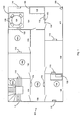
- Figure 1 illustrates a floor 100 of a building which has been fitted with a real time location system embodying the invention.
- the floor 100 is divided into a number of separate spaces 101 to 108.
- 101 is a stairwell with stairs leading up and/or down to floors above and/or below.
- 102 to 107 are various rooms and 108 is a corridor.
- room 105 is a monitoring room containing a central computer 130 which may be monitored by an operator 134. It should be appreciated however that the computer 130 may be located elsewhere within the building or completely off site, connected to the system through a direct connection, or over a network and/or the internet.
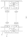
- FIG. 2 schematically illustrates a mobile tag 140 and a base station 110 in communication with each other.
- the base station 110 is fixed to a static structure of the building such as a wall, floor or ceiling. It has a receiver 220 and a transmitter 222. These may be any kind of wireless transmitter and receiver, but most conveniently ultrasound or radio frequency (RF) electromagnetic communication are used. Ultrasound is advantageous in care environments as electromagnetic waves can interfere with other equipment in the building. Ultrasound also does not penetrate the walls and so interference between base stations or from background noise is reduced compared with electromagnetic transmissions. Combinations of ultrasound and electromagnetic communication may be used.
- RF radio frequency
- the base unit 110 includes an air pressure sensor 224 and a temperature sensor 226. These are illustrated separately, but in practice the two sensors could be combined on a single sensor circuit.
- the base unit 110 also includes a processor 228 and memory 230.
- the processor 228 controls the transmitter 222 and receiver 220 for transmitting and receiving data and also reads data from the pressure and temperature sensors 224, 226.
- Memory 230 may be used during the processing procedure and may also store historical data and/or preloaded values such as predetermined values or thresholds for use in calculations and/or database structures (which may be populated or unpopulated with data). All of these data values may be updated during the course of operation.
- the mobile unit or tag 140 is mounted on a strap 202 which can be used to attach the tag 140 to a person or object.
- the strap 202 is an arm band.
- the tag 140 has a transmitter 204 and a receiver 206. As with the base unit 110, these may be ultrasound transducers or RF antennae or combinations of both.
- the tag 140 also has an air pressure sensor 208 and a temperature sensor 210 similar to the base station 110. Again, the transmitter 204, receiver 206, pressure sensor 208 and temperature sensor 210 are all operated by a processor 214 which again has a memory 216 available for use. Additionally, a motion sensor 212 is provided (also connected to the processor 214) for use as described below.
- the units 110, 140 may use the SCP1000 from VTI and/or the MS5607 from MEAS Switzerland. These devices are low power, relatively inexpensive and can provide a height measurement accurate to within 10 cm. Both units also incorporate a temperature sensor.
- Fig. 1 The description below is given in relation to a care environment where the tags 140 are attached to patients and the system is arranged to detect emergency situations when a patient collapses. A number of tags 140a-d are shown in different locations within the floor.
- One or more base stations (base units) 110 are provided per floor 100 of a building, each of which contains an air pressure sensor 224 (shown in Fig. 2 ).
- the base stations 110 are statically located, i.e. they are at known fixed positions. The height above the floor of each base station 110 is known.
- the base station 110 samples the air pressure at regular time intervals. The sampling interval may depend on whether the unit 110 is battery powered or externally powered.
- a tag (mobile unit) 140 is attached to a patient, e.g. via an arm band 202.
- the tag 140 also contains a pressure sensor 208 (shown in Fig. 2 ).
- the air pressure at the tag 140 is transmitted, either via ultrasound (US) or via radio frequency electromagnetic radiation (RF), and the system calculates the difference in air pressure between the tag 140 and the base station 110.
- US ultrasound
- RF radio frequency electromagnetic radiation
- the temperature within the vicinity of a pressure base unit is constant, or alternatively the system can compensate for it as a function of height based on the fact that hot air rises to the ceiling.
- each unit must convert its measured pressure to a reference pressure at a common reference height (e.g. at the floor).
- the temperature gradient may also be measured by using temperature sensors at different heights, e.g. at the floor and at the ceiling (or at the highest relevant height for the installation).
- ⁇ H ⁇ R g ⁇ T ⁇ ⁇ P P
- P the reference pressure
- ⁇ P the pressure difference between the mobile unit and the base unit
- Equation (2) is a low power variant of equation (1) which may be simpler to implement in mobile units.
- the air pressure measurements in the tag 140 and in the base station 110 provide a measure of the height difference between the two. Knowing the height of the base station 110 above the floor, the height of the tag 140 above the floor can be deduced. In particular, it can be determined whether the tag 140 (and the patient) is possibly lying on the floor or not.
- the air pressure measurements are associated with considerable noise.
- the pressure in the region of the sensor will be continually varying due to the constant movement of air due to movement of people, opening of doors, circulation of air caused by fans, etc.
- Signal conditioning such as averaging over multiple samples, low-pass filtering, or Kalman filtering may be applied in order to get a robust measure of the height above the floor.
- the air pressure sensor readings may inherently drift slowly over time. Using multiple base stations 110 with air pressure sensors 224 on the same floor 100, this drift can be averaged out to provide a reference air pressure for the floor (assuming the drift is of a random nature, the drifts from each base station will cancel out when averaging over several base stations).
- Drift in the air pressure sensors 208 in the tags 140 can be compensated in a number of ways.
- Some tags 140 include a motion sensor 212 that can be used to make the tag 140 enter a sleep mode when the tag 140 is stationary. In this mode, the air pressure can be sampled occasionally to compensate for drift. The process of air pressure calibration and drift compensation can be performed in the background even though the mobile unit is stationary (in the case where it has a motion sensor and would otherwise be asleep to save power).
- the tag when the tag is stationary (as indicated for example by the motion sensor), the tag can perform the role of a base station, communicating with the other base stations and improving the reference pressure estimation and saving cost in the infrastructure.
- Another way to compensate for drift in the sensors of the mobile tags 140 is to assume a height band when the system detects motion from room to room.
- a tag 140 attached to a patient's arm can be assumed to be in a rather narrow height band if one can determine that the patient is walking.
- Such an arrangement is illustrated in the corridor 108 of Fig. 1 where mobile unit 140d is passing along the corridor. It should be noted that although two base units 110 are shown in the corridor 108, only one base unit 110 is required for this method of calibration. When the unit 110 detects that the tag 140d is in close proximity (e.g. within a threshold distance), it determines that the patient wearing tag 140d is in the corridor in the vicinity of the base unit 110 and is therefore almost certainly walking.
- the tag 140d is at some predetermined height.
- the predetermined height will vary from patient to patient (according to the patient's height) and is preferably stored in a database on the central computer 130.
- the unit 110 can contact the central computer 130 (either through a direct connection or over a network and either wired or wirelessly) to request the predetermined height for that tag 140d.
- Each tag has a unique identifier which can be read by base unit 110 and sent to the central computer 130.
- the central computer looks up the identifier in its database and returns the appropriate predetermined height to base unit 110. Alternatively all calibration calculations can be performed on the central computer 130 which can then return calibration values (pressure and/or height) to the base station 110.
- base unit 110 can send calibration data (e.g. a current height and/or a corrected pressure reading to the tag 140 so that the tag 140 can recalibrate itself.
- the tag 140 could have the predetermined height programmed into it, e.g. stored in memory 216 (which could be random access memory, flash memory or similar).
- An on board processor unit 214 can perform the recalibration calculations. If the tag 140 is not set up to receive incoming data or instructions then the unit cannot be instructed to recalibrate. Instead, the tag 140d sends its pressure data as normal to the base unit 110 and the base unit 110 (or the central computer 130) determines an error between this reading and the reading that would be expected for the predetermined height.
- This determined error can be stored (e.g. in a database on central computer 130) alongside the unique identifier for tag 140d and used to apply a correction to all data received from tag 140d. Every time the tag 140d passes through a recalibration zone, the calculation can be performed again and the database can be updated with corrected data.
- zones instrumented for full 3D positioning to calibrate the air pressure reading from the tag 140.
- Such zones do not rely on any pressure data in order to determine an accurate height for the tag 140.
- These zones can be deployed for the purpose of general 3D positioning as illustrated in room 104 of Fig. 1 which has three base units 110 attached to the walls and preferably has a further base unit 110 mounted in the ceiling or floor to provide an accurate z-coordinate (i.e. height above the floor). Calibration can be performed in a manner similar to that described previously.
- height estimation infrastructure may be deployed specifically to provide an accurate height measure.
- a series of receivers (which could be a base unit 110) arranged in a vertical array could simultaneously detect the proximity of a tag 140 as it passes by.
- the receiver which receives the strongest signal is determined to be the receiver at the closest height to that of the tag 140 thereby providing a simple yet accurate height detection method.
- the tag If the tag is fitted with two-way communication, the tag can be instructed to enter a frequent update mode to provide accurate position estimation, for example to catch the exact moment when the tag 140 moves through a door.
- Fall detection e.g. the collapse of a patient
- Fall detection can, in the simplest embodiment, be detected simply on the basis of the height of a tag 140 being detected at or near the floor.
- a tag being at or near the floor, such as a patient bending down to pick something up or to access a low drawer or cupboard. Therefore a system relying solely on the current height of a tag is liable to trigger false positive alarms, i.e. the system could raise an alarm when the situation does not require it.
- Such a system is however reasonably robust to false negatives, i.e. it should reliably detect most situations where a patient has collapsed to the floor and correctly raise an alarm.
- fall detection can also be triggered by a sudden drop in height, independent of the reference pressure in the base station 110.
- the mobile unit 140 can raise the alarm itself based solely on its own data.
- the base station 110 can provide extra information about the starting height and finishing height of the tag. For example, the base station 110 can confirm that the tag actually ended up on the floor. An intelligent system can combine these pieces of information and raise an alarm based on the sudden drop in height together with the information that the finishing height is at or near floor level.
- the indoor real time location system may additionally have zoning within rooms.
- the system can identify different areas within the room. Such areas may include areas containing beds, sofas, chairs, stairs, etc that can be associated with typical patient/tag heights, and can provide additional filtering information for providing reliable alarms.
- two special zones have been identified (and programmed into the system) in room 104.
- the first zone 120 is a zone containing a bed 122.
- a tag 140 can be expected to be within a predictable height band and can be expected to remain at that height for some time.
- a second zone 124 contains a table 126 and four chairs 128.
- tags 140 within this zone 124 can be expected to remain mostly within a certain predictable height band, but will be prone to sudden rises and falls as people sit down or get up.
- the heights of the tags 140 should not however end up at floor level.
- the system may also combine time information with the spatial zones, for example time periods may be identified when a person is expected to be in bed 122 or dining at table 126.
- an intelligent building may be equipped with a number of other sensors which can feed data into the position detection system and can be used in determining alert situations.
- Room 107 contains a motion sensor 150 (e.g. an infrared, ultrasound or radar motion detector such as may be used in a burglar alarm system), a light switch sensor 152 which indicates the current state (on/off) of the light, and a door sensor 154 which indicates whether the door is open or closed.
- a motion sensor 150 e.g. an infrared, ultrasound or radar motion detector such as may be used in a burglar alarm system
- a light switch sensor 152 which indicates the current state (on/off) of the light
- a door sensor 154 which indicates whether the door is open or closed.
- indoor real time location systems can provide additional information like motion detection via Doppler shift that can also be used to verify the fall detection alarm.
- the logic for determining an alert situation can be significantly different, depending on the location.
- there could be zones for stairs with dedicated logic such that there will be no alarm when the tag descends towards (and through) the floor level.
- an alarm should be issued if the height remains constant, regardless of the height; or if it reduces too quickly.
- the air pressure sensors can be used to allow three dimensional positioning in an infrastructure deployed for two dimensional positioning. This set up is not only useful for the fall detection case outlined above, but can be used in all situations where three dimensional positioning is useful. The cost benefits of using the pressure sensors in place of additional ultrasound or RF base units still apply in such situations.
- tags 140 and base stations 110 described above can interact easily with existing tags (without pressure sensors) or with two dimensional infrastructure, simply without using the pressure information.
- existing two dimensional infrastructure can be upgraded easily and conveniently simply by adding pressure sensors to existing base units or by replacing old base units with new ones. Such upgrades need not involve installation of additional units to provide full three dimensional positioning.
Priority Applications (1)
| Application Number | Priority Date | Filing Date | Title |
|---|---|---|---|
| PL11776498T PL2630513T3 (pl) | 2010-10-20 | 2011-10-20 | Układ do określania położenia |
Applications Claiming Priority (2)
| Application Number | Priority Date | Filing Date | Title |
|---|---|---|---|
| GBGB1017711.1A GB201017711D0 (en) | 2010-10-20 | 2010-10-20 | Position determination system |
| PCT/GB2011/052033 WO2012052766A2 (en) | 2010-10-20 | 2011-10-20 | Position determination system |
Publications (2)
| Publication Number | Publication Date |
|---|---|
| EP2630513A2 EP2630513A2 (en) | 2013-08-28 |
| EP2630513B1 true EP2630513B1 (en) | 2021-01-06 |
Family
ID=43334107
Family Applications (1)
| Application Number | Title | Priority Date | Filing Date |
|---|---|---|---|
| EP11776498.5A Active EP2630513B1 (en) | 2010-10-20 | 2011-10-20 | Position determination system |
Country Status (9)
| Country | Link |
|---|---|
| US (2) | US9310207B2 (zh) |
| EP (1) | EP2630513B1 (zh) |
| JP (1) | JP5976000B2 (zh) |
| CN (1) | CN103403570A (zh) |
| DK (1) | DK2630513T3 (zh) |
| ES (1) | ES2864746T3 (zh) |
| GB (1) | GB201017711D0 (zh) |
| PL (1) | PL2630513T3 (zh) |
| WO (1) | WO2012052766A2 (zh) |
Cited By (1)
| Publication number | Priority date | Publication date | Assignee | Title |
|---|---|---|---|---|
| US20210286044A1 (en) * | 2018-12-03 | 2021-09-16 | Lac Camera Systems Oy | Self-positioning method, self-positioning system and tracking beacon unit |
Families Citing this family (31)
| Publication number | Priority date | Publication date | Assignee | Title |
|---|---|---|---|---|
| ES2672214T3 (es) * | 2011-11-21 | 2018-06-13 | 9Solutions Oy | Proceso de calibración de altitud |
| CN103379621B9 (zh) * | 2012-04-27 | 2018-03-27 | 华为技术有限公司 | 定位终端的方法、装置和系统 |
| CN102932412B (zh) * | 2012-09-26 | 2016-02-03 | 华为终端有限公司 | 文件传输方法及系统、主控设备 |
| US9357355B2 (en) * | 2013-01-14 | 2016-05-31 | Qualcomm Incorporated | Region determination control |
| US9131347B2 (en) * | 2013-04-26 | 2015-09-08 | Qualcomm Incorporated | Utilizing a pressure profile to determine a location context identifier |
| JP6107409B2 (ja) * | 2013-05-21 | 2017-04-05 | 富士ゼロックス株式会社 | 位置特定処理装置及び位置特定処理プログラム |
| US9970757B2 (en) | 2014-01-08 | 2018-05-15 | Qualcomm Incorporated | Method and apparatus for positioning with always on barometer |
| US10088309B2 (en) * | 2014-05-16 | 2018-10-02 | Qualcomm Incorporated | LAN-based barometric altimetry |
| EP3180586A1 (en) * | 2014-08-12 | 2017-06-21 | Nokia Solutions and Networks Oy | Position determination of network elements and user equipment in indoor environment |
| US9793988B2 (en) | 2014-11-06 | 2017-10-17 | Facebook, Inc. | Alignment in line-of-sight communication networks |
| US9806809B2 (en) | 2014-11-06 | 2017-10-31 | Facebook, Inc. | Deploying line-of-sight communication networks |
| SE538372C2 (en) | 2014-12-23 | 2016-05-31 | Husqvarna Ab | Improved map generation by a robotic work tool |
| US9734682B2 (en) | 2015-03-02 | 2017-08-15 | Enovate Medical, Llc | Asset management using an asset tag device |
| WO2017040027A1 (en) | 2015-09-04 | 2017-03-09 | Nextnav, Llc | Systems and methods for selecting atmospheric data of reference nodes for use in computing the altitude of a receiver |
| JP6724349B2 (ja) * | 2015-11-30 | 2020-07-15 | カシオ計算機株式会社 | 自律移動装置、自律移動方法及びプログラム |
| FR3052263B1 (fr) * | 2016-06-02 | 2019-04-26 | Wyres Sas | Procede de localisation d'elements mobiles |
| JP6370333B2 (ja) * | 2016-06-03 | 2018-08-08 | 株式会社Iijイノベーションインスティテュート | 気圧センサを用いた位置検出システム及び位置検出方法 |
| CA3029216A1 (en) * | 2016-06-23 | 2017-12-28 | Mayo Foundation For Medical Education And Research | Proximity based fall and distress detection systems and methods |
| CN106403891A (zh) * | 2016-08-30 | 2017-02-15 | 深圳还是威健康科技有限公司 | 测量绝对海拨高度的方法及装置 |
| US10254188B2 (en) | 2016-09-09 | 2019-04-09 | Qualcomm Incorporated | Adaptive pressure sensor sampling rate |
| WO2018106562A1 (en) * | 2016-12-05 | 2018-06-14 | Barron Associates, Inc. | Autonomous fall monitor having sensor compensation |
| DE202017100940U1 (de) | 2017-01-18 | 2017-03-06 | Aeris Gmbh | Arbeitsplatzanalysesystem |
| US10616853B2 (en) * | 2017-12-29 | 2020-04-07 | Sonitor Technologies As | Location determination using acoustic-contextual data |
| EP4114060A1 (en) * | 2018-01-10 | 2023-01-04 | E.ON Digital Technology GmbH | Sensor device with one sensor module and system for securely providing analytics results |
| JP7111595B2 (ja) * | 2018-11-29 | 2022-08-02 | 株式会社日立ビルシステム | 作業管理システム |
| CN109587630A (zh) * | 2018-12-26 | 2019-04-05 | 中国矿业大学 | 一种建筑工地组网通信的定位终端和一种定位方法 |
| EP3709276A1 (en) * | 2019-03-12 | 2020-09-16 | Koninklijke Philips N.V. | A method for detecting fall of a user |
| CN110926473B (zh) * | 2019-11-18 | 2022-08-16 | 北京三快在线科技有限公司 | 识别楼层的方法、装置、电子设备及存储介质 |
| US20210243564A1 (en) * | 2020-01-30 | 2021-08-05 | Wiser Systems, Inc. | Real time tracking systems in three dimensions in multi-story structures and related methods and computer program products |
| CN113367685A (zh) * | 2020-03-09 | 2021-09-10 | 瀚谊世界科技股份有限公司 | 气压检测装置、方法与双气压计跌倒检测系统 |
| CN112325845B (zh) * | 2020-10-26 | 2022-09-06 | 的卢技术有限公司 | 一种通过气压信息定位车辆升降高度的方法、装置、车辆及存储介质 |
Citations (1)
| Publication number | Priority date | Publication date | Assignee | Title |
|---|---|---|---|---|
| US20090012818A1 (en) * | 2007-07-06 | 2009-01-08 | Valence Broadband, Inc. | Dispensing medication and verifying proper medication use |
Family Cites Families (26)
| Publication number | Priority date | Publication date | Assignee | Title |
|---|---|---|---|---|
| FR2486662A1 (fr) | 1980-07-09 | 1982-01-15 | Geophysique Cie Gle | Dispositif de video-radiolocalisation aerienne, a haute densite d'informations, notamment pour geodesie et cartographie |
| JPH04369492A (ja) | 1991-06-18 | 1992-12-22 | Pioneer Electron Corp | Gps測位装置 |
| US5652592A (en) | 1995-06-06 | 1997-07-29 | Sanconix, Inc | Radio location with enhanced Z-axis determination |
| US6160478A (en) * | 1998-10-27 | 2000-12-12 | Sarcos Lc | Wireless health monitoring system |
| GB9907123D0 (en) * | 1999-03-26 | 1999-05-19 | Bide Stephen | Position finding |
| US6196355B1 (en) * | 1999-03-26 | 2001-03-06 | Otis Elevator Company | Elevator rescue system |
| EP1115241A3 (en) | 2000-01-07 | 2003-07-16 | Motorola, Inc. | A portable communication device with means for measuring the altitude |
| US6333694B2 (en) * | 2000-03-09 | 2001-12-25 | Advanced Marketing Systems Corporation | Personal emergency response system |
| US6518918B1 (en) | 2000-05-11 | 2003-02-11 | Lucent Technologies Inc. | Wireless assisted altitude measurement |
| JP3808294B2 (ja) * | 2000-08-07 | 2006-08-09 | セイコーインスツル株式会社 | 携帯型圧力測定装置 |
| JP2004045274A (ja) * | 2002-07-12 | 2004-02-12 | Denso Corp | 無線通信機能付移動端末、基地局及び無線通信システム |
| JP4059716B2 (ja) | 2002-07-12 | 2008-03-12 | オリンパス株式会社 | 光機能デバイス |
| JP2004220241A (ja) | 2003-01-14 | 2004-08-05 | Matsushita Electric Ind Co Ltd | 場所確認機能を搭載した緊急発報システム |
| JP4333603B2 (ja) * | 2005-02-18 | 2009-09-16 | 日本電信電話株式会社 | 転倒管理サーバ、プログラム、及び履物 |
| FI117009B (fi) * | 2005-03-08 | 2006-05-15 | Kone Corp | Opastusjärjestelmä |
| FR2888940A1 (fr) | 2005-07-22 | 2007-01-26 | Cryptiris Soc Par Actions Simp | Systeme de localisation par utilisation combinee de mesures de pression atmospherique et d'analyse de reception d'ondes electromagnetiques |
| GB2430524A (en) * | 2005-09-23 | 2007-03-28 | Avantone Oy | Mobile information processing system |
| TR201900727T4 (tr) * | 2005-09-30 | 2019-02-21 | Inventio Ag | Bir bina alanından yolcuların ve/veya yüklerin transfer edilmesi için asansör sistemi. |
| US8274564B2 (en) * | 2006-10-13 | 2012-09-25 | Fuji Xerox Co., Ltd. | Interface for browsing and viewing video from multiple cameras simultaneously that conveys spatial and temporal proximity |
| JP5009022B2 (ja) | 2007-03-27 | 2012-08-22 | 富士通株式会社 | 携帯端末装置、その高度の計測方法、その計測プログラム、及びその計測プログラムを格納した記録媒体 |
| WO2009062305A1 (en) | 2007-11-13 | 2009-05-22 | Novatel Inc. | System for determining position over a network |
| JP2009281741A (ja) * | 2008-05-19 | 2009-12-03 | Freescale Semiconductor Inc | 現在位置出力装置、現在位置出力方法及び現在位置出力プログラム |
| WO2009150251A2 (de) * | 2008-06-13 | 2009-12-17 | Inventio Ag | Aufzugsanlage und verfahren zur wartung einer solchen aufzugsanlage |
| JP2009301450A (ja) | 2008-06-17 | 2009-12-24 | Yokogawa Electric Corp | 状態検知端末を用いた監視システム |
| US7893844B2 (en) | 2008-06-27 | 2011-02-22 | Mark Gottlieb | Fall detection system having a floor height threshold and a resident height detection device |
| US20100052896A1 (en) * | 2008-09-02 | 2010-03-04 | Jesse Bruce Goodman | Fall detection system and method |
-
2010
- 2010-10-20 GB GBGB1017711.1A patent/GB201017711D0/en not_active Ceased
-
2011
- 2011-10-20 US US13/880,928 patent/US9310207B2/en active Active
- 2011-10-20 JP JP2013534385A patent/JP5976000B2/ja not_active Expired - Fee Related
- 2011-10-20 EP EP11776498.5A patent/EP2630513B1/en active Active
- 2011-10-20 ES ES11776498T patent/ES2864746T3/es active Active
- 2011-10-20 CN CN2011800584981A patent/CN103403570A/zh active Pending
- 2011-10-20 WO PCT/GB2011/052033 patent/WO2012052766A2/en active Application Filing
- 2011-10-20 PL PL11776498T patent/PL2630513T3/pl unknown
- 2011-10-20 DK DK11776498.5T patent/DK2630513T3/da active
-
2016
- 2016-03-10 US US15/066,763 patent/US10368783B2/en active Active
Patent Citations (1)
| Publication number | Priority date | Publication date | Assignee | Title |
|---|---|---|---|---|
| US20090012818A1 (en) * | 2007-07-06 | 2009-01-08 | Valence Broadband, Inc. | Dispensing medication and verifying proper medication use |
Cited By (2)
| Publication number | Priority date | Publication date | Assignee | Title |
|---|---|---|---|---|
| US20210286044A1 (en) * | 2018-12-03 | 2021-09-16 | Lac Camera Systems Oy | Self-positioning method, self-positioning system and tracking beacon unit |
| US11774547B2 (en) * | 2018-12-03 | 2023-10-03 | Lac Camera Systems Oy | Self-positioning method, self-positioning system and tracking beacon unit |
Also Published As
| Publication number | Publication date |
|---|---|
| US10368783B2 (en) | 2019-08-06 |
| CN103403570A (zh) | 2013-11-20 |
| EP2630513A2 (en) | 2013-08-28 |
| JP5976000B2 (ja) | 2016-08-23 |
| WO2012052766A2 (en) | 2012-04-26 |
| DK2630513T3 (da) | 2021-04-06 |
| ES2864746T3 (es) | 2021-10-14 |
| WO2012052766A3 (en) | 2013-03-07 |
| US20160192864A1 (en) | 2016-07-07 |
| US9310207B2 (en) | 2016-04-12 |
| US20130307696A1 (en) | 2013-11-21 |
| PL2630513T3 (pl) | 2021-11-02 |
| GB201017711D0 (en) | 2010-12-01 |
| JP2013543968A (ja) | 2013-12-09 |
Similar Documents
| Publication | Publication Date | Title |
|---|---|---|
| US10368783B2 (en) | Position determination system | |
| US7471242B2 (en) | Method and apparatus for installing and/or determining the position of a receiver of a tracking system | |
| US10412541B2 (en) | Real-time location system (RTLS) that uses a combination of bed-and-bay-level event sensors and RSSI measurements to determine bay-location of tags | |
| US20070132577A1 (en) | Method and apparatus for estimating the location of a signal transmitter | |
| JP5975973B2 (ja) | 空気調和制御装置および空気調和システム | |
| US20070132576A1 (en) | Method and apparatus for tracking persons | |
| EP3528259B1 (en) | Historical identification and accuracy compensation for problem areas in a locating system | |
| KR20140043430A (ko) | 관측을 위한 방법 및 시스템 | |
| JP2007150435A (ja) | 通信システム | |
| WO2013169612A1 (en) | Low frequency magnetic induction positioning system and method | |
| US7859418B2 (en) | Apparatus, system and method for sensing to locate persons in a building in the event of a disaster | |
| KR101982404B1 (ko) | 비콘 기반 환자 모니터링 방법 및 모니터링 시스템 | |
| US20240077603A1 (en) | Sensor and system for monitoring | |
| EP3807853A1 (en) | A real-time location system (rtls) that uses a combination of event sensors and rssi measurements to determine room-and-bay-location of tags | |
| CN111759273A (zh) | 行为追踪方法及装置 | |
| KR102476688B1 (ko) | 병실 관리 시스템 및 그 방법 | |
| US8902062B2 (en) | Systems and methods for detection of device displacement and tampering | |
| US20230196897A1 (en) | A device and method for determining a status of a person | |
| WO2020012144A1 (en) | Determining presence of a person | |
| GB2535984A (en) | Healthcare monitoring and alarm system |
Legal Events
| Date | Code | Title | Description |
|---|---|---|---|
| PUAI | Public reference made under article 153(3) epc to a published international application that has entered the european phase |
Free format text: ORIGINAL CODE: 0009012 |
|
| 17P | Request for examination filed |
Effective date: 20130425 |
|
| AK | Designated contracting states |
Kind code of ref document: A2 Designated state(s): AL AT BE BG CH CY CZ DE DK EE ES FI FR GB GR HR HU IE IS IT LI LT LU LV MC MK MT NL NO PL PT RO RS SE SI SK SM TR |
|
| DAX | Request for extension of the european patent (deleted) | ||
| 17Q | First examination report despatched |
Effective date: 20160510 |
|
| STAA | Information on the status of an ep patent application or granted ep patent |
Free format text: STATUS: EXAMINATION IS IN PROGRESS |
|
| GRAP | Despatch of communication of intention to grant a patent |
Free format text: ORIGINAL CODE: EPIDOSNIGR1 |
|
| STAA | Information on the status of an ep patent application or granted ep patent |
Free format text: STATUS: GRANT OF PATENT IS INTENDED |
|
| RIC1 | Information provided on ipc code assigned before grant |
Ipc: G01S 5/18 20060101AFI20200114BHEP Ipc: G01S 5/02 20100101ALN20200114BHEP Ipc: G01C 21/20 20060101ALI20200114BHEP Ipc: G01C 5/06 20060101ALI20200114BHEP Ipc: A61B 5/11 20060101ALI20200114BHEP Ipc: G08B 21/04 20060101ALI20200114BHEP |
|
| INTG | Intention to grant announced |
Effective date: 20200207 |
|
| GRAJ | Information related to disapproval of communication of intention to grant by the applicant or resumption of examination proceedings by the epo deleted |
Free format text: ORIGINAL CODE: EPIDOSDIGR1 |
|
| REG | Reference to a national code |
Ref country code: DE Ref legal event code: R079 Ref document number: 602011069888 Country of ref document: DE Free format text: PREVIOUS MAIN CLASS: G01S0005000000 Ipc: G01S0005180000 |
|
| STAA | Information on the status of an ep patent application or granted ep patent |
Free format text: STATUS: EXAMINATION IS IN PROGRESS |
|
| GRAP | Despatch of communication of intention to grant a patent |
Free format text: ORIGINAL CODE: EPIDOSNIGR1 |
|
| STAA | Information on the status of an ep patent application or granted ep patent |
Free format text: STATUS: GRANT OF PATENT IS INTENDED |
|
| INTC | Intention to grant announced (deleted) | ||
| RIC1 | Information provided on ipc code assigned before grant |
Ipc: A61B 5/11 20060101ALI20200619BHEP Ipc: G01C 21/20 20060101ALI20200619BHEP Ipc: G01C 5/06 20060101ALI20200619BHEP Ipc: G08B 21/04 20060101ALI20200619BHEP Ipc: G01S 5/02 20100101ALN20200619BHEP Ipc: G01S 5/18 20060101AFI20200619BHEP |
|
| INTG | Intention to grant announced |
Effective date: 20200715 |
|
| GRAS | Grant fee paid |
Free format text: ORIGINAL CODE: EPIDOSNIGR3 |
|
| GRAA | (expected) grant |
Free format text: ORIGINAL CODE: 0009210 |
|
| STAA | Information on the status of an ep patent application or granted ep patent |
Free format text: STATUS: THE PATENT HAS BEEN GRANTED |
|
| AK | Designated contracting states |
Kind code of ref document: B1 Designated state(s): AL AT BE BG CH CY CZ DE DK EE ES FI FR GB GR HR HU IE IS IT LI LT LU LV MC MK MT NL NO PL PT RO RS SE SI SK SM TR |
|
| REG | Reference to a national code |
Ref country code: GB Ref legal event code: FG4D |
|
| REG | Reference to a national code |
Ref country code: AT Ref legal event code: REF Ref document number: 1352967 Country of ref document: AT Kind code of ref document: T Effective date: 20210115 Ref country code: CH Ref legal event code: EP |
|
| REG | Reference to a national code |
Ref country code: DE Ref legal event code: R096 Ref document number: 602011069888 Country of ref document: DE |
|
| REG | Reference to a national code |
Ref country code: IE Ref legal event code: FG4D |
|
| REG | Reference to a national code |
Ref country code: DK Ref legal event code: T3 Effective date: 20210331 |
|
| REG | Reference to a national code |
Ref country code: FI Ref legal event code: FGE |
|
| REG | Reference to a national code |
Ref country code: NL Ref legal event code: FP |
|
| REG | Reference to a national code |
Ref country code: SE Ref legal event code: TRGR |
|
| REG | Reference to a national code |
Ref country code: NO Ref legal event code: T2 Effective date: 20210106 |
|
| REG | Reference to a national code |
Ref country code: AT Ref legal event code: MK05 Ref document number: 1352967 Country of ref document: AT Kind code of ref document: T Effective date: 20210106 |
|
| REG | Reference to a national code |
Ref country code: LT Ref legal event code: MG9D |
|
| PG25 | Lapsed in a contracting state [announced via postgrant information from national office to epo] |
Ref country code: GR Free format text: LAPSE BECAUSE OF FAILURE TO SUBMIT A TRANSLATION OF THE DESCRIPTION OR TO PAY THE FEE WITHIN THE PRESCRIBED TIME-LIMIT Effective date: 20210407 Ref country code: HR Free format text: LAPSE BECAUSE OF FAILURE TO SUBMIT A TRANSLATION OF THE DESCRIPTION OR TO PAY THE FEE WITHIN THE PRESCRIBED TIME-LIMIT Effective date: 20210106 Ref country code: PT Free format text: LAPSE BECAUSE OF FAILURE TO SUBMIT A TRANSLATION OF THE DESCRIPTION OR TO PAY THE FEE WITHIN THE PRESCRIBED TIME-LIMIT Effective date: 20210506 Ref country code: LT Free format text: LAPSE BECAUSE OF FAILURE TO SUBMIT A TRANSLATION OF THE DESCRIPTION OR TO PAY THE FEE WITHIN THE PRESCRIBED TIME-LIMIT Effective date: 20210106 Ref country code: BG Free format text: LAPSE BECAUSE OF FAILURE TO SUBMIT A TRANSLATION OF THE DESCRIPTION OR TO PAY THE FEE WITHIN THE PRESCRIBED TIME-LIMIT Effective date: 20210406 |
|
| PG25 | Lapsed in a contracting state [announced via postgrant information from national office to epo] |
Ref country code: AT Free format text: LAPSE BECAUSE OF FAILURE TO SUBMIT A TRANSLATION OF THE DESCRIPTION OR TO PAY THE FEE WITHIN THE PRESCRIBED TIME-LIMIT Effective date: 20210106 Ref country code: RS Free format text: LAPSE BECAUSE OF FAILURE TO SUBMIT A TRANSLATION OF THE DESCRIPTION OR TO PAY THE FEE WITHIN THE PRESCRIBED TIME-LIMIT Effective date: 20210106 Ref country code: LV Free format text: LAPSE BECAUSE OF FAILURE TO SUBMIT A TRANSLATION OF THE DESCRIPTION OR TO PAY THE FEE WITHIN THE PRESCRIBED TIME-LIMIT Effective date: 20210106 |
|
| PG25 | Lapsed in a contracting state [announced via postgrant information from national office to epo] |
Ref country code: IS Free format text: LAPSE BECAUSE OF FAILURE TO SUBMIT A TRANSLATION OF THE DESCRIPTION OR TO PAY THE FEE WITHIN THE PRESCRIBED TIME-LIMIT Effective date: 20210506 |
|
| REG | Reference to a national code |
Ref country code: DE Ref legal event code: R097 Ref document number: 602011069888 Country of ref document: DE |
|
| REG | Reference to a national code |
Ref country code: ES Ref legal event code: FG2A Ref document number: 2864746 Country of ref document: ES Kind code of ref document: T3 Effective date: 20211014 |
|
| PG25 | Lapsed in a contracting state [announced via postgrant information from national office to epo] |
Ref country code: SM Free format text: LAPSE BECAUSE OF FAILURE TO SUBMIT A TRANSLATION OF THE DESCRIPTION OR TO PAY THE FEE WITHIN THE PRESCRIBED TIME-LIMIT Effective date: 20210106 Ref country code: EE Free format text: LAPSE BECAUSE OF FAILURE TO SUBMIT A TRANSLATION OF THE DESCRIPTION OR TO PAY THE FEE WITHIN THE PRESCRIBED TIME-LIMIT Effective date: 20210106 Ref country code: CZ Free format text: LAPSE BECAUSE OF FAILURE TO SUBMIT A TRANSLATION OF THE DESCRIPTION OR TO PAY THE FEE WITHIN THE PRESCRIBED TIME-LIMIT Effective date: 20210106 |
|
| PLBE | No opposition filed within time limit |
Free format text: ORIGINAL CODE: 0009261 |
|
| STAA | Information on the status of an ep patent application or granted ep patent |
Free format text: STATUS: NO OPPOSITION FILED WITHIN TIME LIMIT |
|
| PG25 | Lapsed in a contracting state [announced via postgrant information from national office to epo] |
Ref country code: SK Free format text: LAPSE BECAUSE OF FAILURE TO SUBMIT A TRANSLATION OF THE DESCRIPTION OR TO PAY THE FEE WITHIN THE PRESCRIBED TIME-LIMIT Effective date: 20210106 Ref country code: RO Free format text: LAPSE BECAUSE OF FAILURE TO SUBMIT A TRANSLATION OF THE DESCRIPTION OR TO PAY THE FEE WITHIN THE PRESCRIBED TIME-LIMIT Effective date: 20210106 |
|
| 26N | No opposition filed |
Effective date: 20211007 |
|
| PG25 | Lapsed in a contracting state [announced via postgrant information from national office to epo] |
Ref country code: AL Free format text: LAPSE BECAUSE OF FAILURE TO SUBMIT A TRANSLATION OF THE DESCRIPTION OR TO PAY THE FEE WITHIN THE PRESCRIBED TIME-LIMIT Effective date: 20210106 |
|
| PG25 | Lapsed in a contracting state [announced via postgrant information from national office to epo] |
Ref country code: SI Free format text: LAPSE BECAUSE OF FAILURE TO SUBMIT A TRANSLATION OF THE DESCRIPTION OR TO PAY THE FEE WITHIN THE PRESCRIBED TIME-LIMIT Effective date: 20210106 |
|
| PG25 | Lapsed in a contracting state [announced via postgrant information from national office to epo] |
Ref country code: IS Free format text: LAPSE BECAUSE OF FAILURE TO SUBMIT A TRANSLATION OF THE DESCRIPTION OR TO PAY THE FEE WITHIN THE PRESCRIBED TIME-LIMIT Effective date: 20210506 |
|
| REG | Reference to a national code |
Ref country code: BE Ref legal event code: MM Effective date: 20211031 |
|
| PG25 | Lapsed in a contracting state [announced via postgrant information from national office to epo] |
Ref country code: MC Free format text: LAPSE BECAUSE OF FAILURE TO SUBMIT A TRANSLATION OF THE DESCRIPTION OR TO PAY THE FEE WITHIN THE PRESCRIBED TIME-LIMIT Effective date: 20210106 |
|
| PG25 | Lapsed in a contracting state [announced via postgrant information from national office to epo] |
Ref country code: LU Free format text: LAPSE BECAUSE OF NON-PAYMENT OF DUE FEES Effective date: 20211020 Ref country code: BE Free format text: LAPSE BECAUSE OF NON-PAYMENT OF DUE FEES Effective date: 20211031 |
|
| PG25 | Lapsed in a contracting state [announced via postgrant information from national office to epo] |
Ref country code: IE Free format text: LAPSE BECAUSE OF NON-PAYMENT OF DUE FEES Effective date: 20211020 |
|
| PG25 | Lapsed in a contracting state [announced via postgrant information from national office to epo] |
Ref country code: HU Free format text: LAPSE BECAUSE OF FAILURE TO SUBMIT A TRANSLATION OF THE DESCRIPTION OR TO PAY THE FEE WITHIN THE PRESCRIBED TIME-LIMIT; INVALID AB INITIO Effective date: 20111020 Ref country code: CY Free format text: LAPSE BECAUSE OF FAILURE TO SUBMIT A TRANSLATION OF THE DESCRIPTION OR TO PAY THE FEE WITHIN THE PRESCRIBED TIME-LIMIT Effective date: 20210106 |
|
| P01 | Opt-out of the competence of the unified patent court (upc) registered |
Effective date: 20230526 |
|
| PGFP | Annual fee paid to national office [announced via postgrant information from national office to epo] |
Ref country code: NL Payment date: 20231019 Year of fee payment: 13 |
|
| PGFP | Annual fee paid to national office [announced via postgrant information from national office to epo] |
Ref country code: GB Payment date: 20231018 Year of fee payment: 13 |
|
| PGFP | Annual fee paid to national office [announced via postgrant information from national office to epo] |
Ref country code: ES Payment date: 20231101 Year of fee payment: 13 |
|
| PGFP | Annual fee paid to national office [announced via postgrant information from national office to epo] |
Ref country code: TR Payment date: 20231010 Year of fee payment: 13 Ref country code: SE Payment date: 20231023 Year of fee payment: 13 Ref country code: NO Payment date: 20231020 Year of fee payment: 13 Ref country code: IT Payment date: 20231023 Year of fee payment: 13 Ref country code: FR Payment date: 20231018 Year of fee payment: 13 Ref country code: FI Payment date: 20231025 Year of fee payment: 13 Ref country code: DK Payment date: 20231023 Year of fee payment: 13 Ref country code: DE Payment date: 20231020 Year of fee payment: 13 Ref country code: CH Payment date: 20231101 Year of fee payment: 13 |
|
| PGFP | Annual fee paid to national office [announced via postgrant information from national office to epo] |
Ref country code: PL Payment date: 20231010 Year of fee payment: 13 |
|
| PG25 | Lapsed in a contracting state [announced via postgrant information from national office to epo] |
Ref country code: MK Free format text: LAPSE BECAUSE OF FAILURE TO SUBMIT A TRANSLATION OF THE DESCRIPTION OR TO PAY THE FEE WITHIN THE PRESCRIBED TIME-LIMIT Effective date: 20210106 |