EP2628829B1 - Stretching unit for stretching a rove - Google Patents
Stretching unit for stretching a rove Download PDFInfo
- Publication number
- EP2628829B1 EP2628829B1 EP13000160.5A EP13000160A EP2628829B1 EP 2628829 B1 EP2628829 B1 EP 2628829B1 EP 13000160 A EP13000160 A EP 13000160A EP 2628829 B1 EP2628829 B1 EP 2628829B1
- Authority
- EP
- European Patent Office
- Prior art keywords
- cage element
- rollers
- spring
- roller
- stretching unit
- Prior art date
- Legal status (The legal status is an assumption and is not a legal conclusion. Google has not performed a legal analysis and makes no representation as to the accuracy of the status listed.)
- Active
Links
- 238000005056 compaction Methods 0.000 claims description 3
- 238000009987 spinning Methods 0.000 description 12
- 230000006835 compression Effects 0.000 description 9
- 238000007906 compression Methods 0.000 description 9
- 230000005540 biological transmission Effects 0.000 description 5
- 239000000835 fiber Substances 0.000 description 4
- 230000000694 effects Effects 0.000 description 3
- 238000007378 ring spinning Methods 0.000 description 3
- 238000005096 rolling process Methods 0.000 description 3
- 239000004753 textile Substances 0.000 description 3
- 230000015572 biosynthetic process Effects 0.000 description 2
- 230000003068 static effect Effects 0.000 description 2
- 230000003321 amplification Effects 0.000 description 1
- 238000010276 construction Methods 0.000 description 1
- 230000001419 dependent effect Effects 0.000 description 1
- 230000006866 deterioration Effects 0.000 description 1
- 230000002045 lasting effect Effects 0.000 description 1
- 238000000034 method Methods 0.000 description 1
- 238000003199 nucleic acid amplification method Methods 0.000 description 1
- 238000004080 punching Methods 0.000 description 1
- 230000000284 resting effect Effects 0.000 description 1
- 238000009420 retrofitting Methods 0.000 description 1
- 239000013589 supplement Substances 0.000 description 1
- 230000003313 weakening effect Effects 0.000 description 1
Images


Classifications
-
- D—TEXTILES; PAPER
- D01—NATURAL OR MAN-MADE THREADS OR FIBRES; SPINNING
- D01H—SPINNING OR TWISTING
- D01H5/00—Drafting machines or arrangements ; Threading of roving into drafting machine
- D01H5/18—Drafting machines or arrangements without fallers or like pinned bars
- D01H5/46—Loading arrangements
- D01H5/50—Loading arrangements using springs
-
- D—TEXTILES; PAPER
- D01—NATURAL OR MAN-MADE THREADS OR FIBRES; SPINNING
- D01H—SPINNING OR TWISTING
- D01H5/00—Drafting machines or arrangements ; Threading of roving into drafting machine
- D01H5/18—Drafting machines or arrangements without fallers or like pinned bars
- D01H5/26—Drafting machines or arrangements without fallers or like pinned bars in which fibres are controlled by one or more endless aprons
Definitions
- the invention relates to a drafting system for warping a roving according to the preamble of claim 1.
- Draw frames for warping rovings are widely used in the textile industry and are used on various textile machines.
- the work stations of ring spinning machines are equipped, for example, with drafting devices which draw a roving unwound from a flyer bobbin into a sliver of high fineness, which is subsequently provided with a twist and wound up as a finished yarn on a spinning cop.
- Such drafting systems usually have three machine-length, driven by a machine end side drive at different rotational speeds, spaced arranged lower rollers, and each three associated, arranged on a pivotally mounted pendulum carrier top rollers.
- the top rollers lie during the spinning operation with a predetermined contact pressure on the driven bottom rollers and are driven by these frictionally. That is, the upper rollers form with the associated lower rollers roller pairs, which ensure because of their different rotational speeds that the submitted roving is distorted when passing through the drafting system.
- such drafting systems typically include an input, a center and an output roller pair, the area between the input and center roller pairs forms a so-called Vorverzugsfeld, while the area between the middle and the output roller pair acts as a main drafting field.
- the supplied roving is warped in the drafting to the desired fineness and leaves the drafting at the nip of the pair of delivery rollers as a relatively wide, for example, up to 50 times warped sliver.
- this relatively wide sliver is then acted upon by a spinning spinning cop in conjunction with an associated ring traveler of the relevant work site with spin rotation and thereby twisted into a finished yarn.
- special compression devices are arranged between the pairs of output rollers and the pairs of delivery rollers, which can be designed, for example, as mechanical compressors or can operate pneumatically.
- the output top rollers arranged in front of the compaction zone and the upper top delivery rollers arranged downstream of the compaction zone are mounted in a common cage element in such a way that the axes of the roller pairs are guided parallel to one another. That is, the cage element covered with a first axis guide means the axis of the top rollers at the side of the saddle, which in turn is arranged in a so-called output link of the pendulum carrier and held there by a saddle spring.
- the output link is usually acted upon by a spring element so that the Ninoberwalzen rest with a defined contact pressure on the associated output lower rollers.
- the delivery top rollers must also rest on the delivery bottom rollers with a specific loading force, since this is the only way to ensure that the compacted fibers are properly transported even in the area of the compression zone.
- various methods or devices are known.
- the cage element with a molded surface, which is arranged and designed so that the cage element in the installed state and with closed pendulum carrier on the underside of the output link supported. That is, the loading force introduced from the output link is transmitted to the cage member via the integrally formed surface and distributed to the output top rollers and the delivery top rollers at respective intervals.
- a disadvantage of this known type of connection of delivery top rollers is, inter alia, that the output top rollers are often dug something out of their leadership and receiving device in the cage element, with the result that the top rollers are no longer exactly out, which in principle to a deterioration of the yarn quality leads.
- Retrofitting of the known drafting systems for example by a significant increase in the maximum load force of the output link, brought no lasting success, since such a significant increase in the loading force not only led to settlement effects on the top rollers, which also has a negative effect on the achievable yarn quality, but also a defined setting of the optimal loading force of the top roller pairs very difficult.
- the additional leaf spring can either, as in the DE 100 05 387 A1 described, be attached to the pendulum carrier of the drafting system, for example via a screw, or, as by the DE 10 2009 050 581 A1 known to be stationarily arranged on the cage element.
- the present invention seeks to further develop a drafting system for warping roving so that always a constant loading force can be ensured during the spinning operation even with counting for the compression zone delivery top rollers.
- the inventive construction in which the cage element has a first guide and receiving device, the lights Diameter slightly above the diameter of the axis of the pair of output rollers, on which the cage member is mounted and connected to the loading spring at one end stationary to the pendulum carrier of the drafting and in the region of its opposite, free end via a movable intermediate member with the delivery top rollers or the Morrisvorwalzen receiving cage member is connected, has the advantage that in this way a frictional bearing of the loading spring on the cage element can be largely prevented and ensured that the loading spring on the movable intermediate link quasi frictionless on the delivery top rollers or the cage element and thus also on the delivery top rollers transfers.
- the light diameter is slightly greater than the diameter of the axis on which the cage member is mounted, which is therefore with some play on their associated bearing axis, it is also ensured that the cage element almost force-free order can pivot its bearing axis.
- the intermediate member is designed as a rolling body, the is movably mounted in a guide device of the cage element.
- movably mounted rolling body works not only during the spinning operation very reliable, but also represents a cost-effective component, which has a long life.
- the loading spring is designed as an L-shaped bent leaf spring whose first leg is fixedly fixed to the pendulum carrier, while the second, free leg rests on a movable intermediate member.
- Such a trained loading spring is on the one hand securely fixed in a predetermined mounting position and on the other hand in a simple manner so positioned that a quasi-friction transmission of the loading forces is given.
- the loaded by the loading spring movable intermediate member is formed by the axis of the delivery top rollers, which is freely rotatably mounted in such a case in a second guiding and receiving device of the cage element.
- Such a design has the advantage, for example, that the loading spring presses directly on the saddle piece of the axis of the top delivery roller pair; So the loading force does not have to take the detour via the cage element.
- the arranged in the cage element guide and receiving means for the axis of Railoberwalzencrues of the cage element is designed as a fork guide whose longitudinal direction is approximately tangential to a circular path, which perform the delivery top rollers in an up and down movement around the Ninoberwalze ,
- a fork guide whose longitudinal direction is approximately tangential to a circular path, which perform the delivery top rollers in an up and down movement around the Ninoberwalze .
- a further advantageous embodiment is in particular also given when the axis of the delivery top rollers is acted upon by an L-shaped angled leaf spring, wherein the resting on the axis of the delivery top rollers free leg of the leaf spring in turn is angled twice.
- the movable intermediate member is designed as a handlebar.
- the handlebar is rounded in the region of its two end faces and is, limitedly movable and acted upon by a loading spring, in a recess of the cage element.
- Such a handlebar which is rounded at both ends, also makes possible an almost hysteresis-free transmission of a constant loading force, preferably provided by a leaf spring.
- Fig. 1 shown drafting device 1 has, as is known, via an input roller pair 2, a middle roller pair 3 and a pair of output rollers 4, wherein the pairs of rollers 2, 3, 4 are each formed by bottom rollers and associated top rollers.
- the generally machine-length for example, by a machine end side arranged drive and a corresponding gear assembly with different rotational speeds driven lower rollers are mounted on (not shown) punching on the machine frame of the ring spinning machine, while the upper rollers which are frictionally driven by the lower rollers during the spinning operation, respectively are connected via so-called handlebars to a pendulum carrier 5, which in turn is fixed via a support 28 to a holding rod 12 fixed to the machine frame.
- the pendulum carrier 5 can be positioned by means of an operating lever 6 in the positions “drafting system up” or “drafting system loaded”, with a third position “drafting relieved “adjusts when the upper rollers rest on the lower rollers without the operating lever 6 is in its closed position.
- Such drafting units 1 have between the pair of input rollers 2 and the pair of output rollers 4, a draft zone 30 in which the supplied roving 26 is preferably warped up to 50 times its input length.
- the drafting zone 30 is divided into the intermediate delay zone 7 lying between the pair of input rollers 2 and the middle roller pair 3 and the main drafting zone 8 located between the middle roller pair 3 and the pair of delivery rollers 4.
- a compression zone 10 connects, which is located between the pair of output rollers 4 and the pair of delivery rollers 11.
- the skilletoberwalzencru 4o is connected via a spring-loaded output link 9 to the pendulum carrier 5, that is, the axis 13 of the réelleoberwalzencrues 4o is secured with its saddle in a receptacle of the output link 9, preferably secured by a spring element.
- a cage element 25 is arranged with a first guiding and receiving device 29 with play.
- the cage member 25 has, in addition to the first guide and receiving means 29 for the axis 13 of Honoberwalzencrues 4o nor a second guide and receiving means 31 for the axis 17 of Dolphinoberwalzencrues 11o and a guide means 19 for a movable intermediate member 16.
- the displaceably mounted in the cage member 25 in the guide means 19 intermediate member 16 is formed as a rolling body and is in the assembled state by the free leg 21 of an L-shaped loading spring 15 is applied, which is fixed with its second leg 20 stationary on the pendulum carrier 5 of the drafting system 1.
- the Fig.2 shows a second embodiment of the pendulum carrier 5 a drafting 1 arranged delay zone 10th
- a cage member 25 is also supported in this embodiment on the axis 13 of the réelleoberwalzencrues 4o with a first guide and receiving device 29, which in addition to the first guide and receiving device 29, a second guide and receiving device 31 for the axis 17 of Dolphinoberwalzencrues 11o has.
- the clear diameter of the first guiding and receiving device 29 is also above the diameter of the axis 13.
- the axis 17 acts as a movable intermediate member and is therefore freely rotatably mounted in the second guide and receiving device 31 of the cage member 25.
- the freely rotatably mounted shaft 17 is acted upon by the free leg 21 of an L-shaped loading spring 15, wherein the free leg 21 is preferably angled twice.
- the loading spring 15 is also fixed here with its second leg 20 on the pendulum carrier 5 of the drafting system 1.
- the rotatable mounting of acting as an intermediate member 17 of the delivery roller upper pair 11o also allows an almost hysteresis-free transmission of the predetermined by the loading spring 15 loading force on the Kayoberwalzencru 11o, the respective effective load force is almost independent of the concentricity of the Underwalzenunterpases 11u.
- the handlebar 18 has the front side each have a radius 23 and 24 and is limitedly movable in a recess 27 of the cage member 25 mounted.
- the handlebar 18 is acted upon by the free leg 21 of an L-shaped loading spring 15, which is fixed with its second leg 20, similar to the embodiments described above, stationary on the pendulum carrier 5.
- the movable arrangement of acting as an intermediate link arm 18 also reliably prevents that, in particular in a non-circular running of Kayunterwalzen 11u, may occur in connection with the work of the loading spring 15 to the occurrence of static friction.
Description
Die Erfindung betrifft ein Streckwerk zum Verziehen eines Vorgarns gemäß dem Oberbegriff des Anspruchs 1.The invention relates to a drafting system for warping a roving according to the preamble of
Streckwerke zum Verziehen von Vorgarnen sind in der Textilindustrie weit verbreitet und kommen an unterschiedlichen Textilmaschinen zum Einsatz.Draw frames for warping rovings are widely used in the textile industry and are used on various textile machines.
Die Arbeitsstellen von Ringspinnmaschinen sind beispielsweise mit Streckwerken ausgestattet, die ein von einer Flyerspule abgewickeltes Vorgarn zu einem Faserband von hoher Feinheit verziehen, das anschließend mit einer Drehung versehen und als fertiges Garn auf einen Spinnkops aufgewickelt wird.The work stations of ring spinning machines are equipped, for example, with drafting devices which draw a roving unwound from a flyer bobbin into a sliver of high fineness, which is subsequently provided with a twist and wound up as a finished yarn on a spinning cop.
Derartige Streckwerke weisen in der Regel drei maschinenlange, von einem maschinenendseitig angeordneten Antrieb mit unterschiedlichen Rotationsgeschwindigkeiten angetriebene, beabstandet angeordnete Unterwalzen, sowie jeweils drei zugehörige, an einem schwenkbar gelagerten Pendelträger angeordnete Oberwalzen auf.Such drafting systems usually have three machine-length, driven by a machine end side drive at different rotational speeds, spaced arranged lower rollers, and each three associated, arranged on a pivotally mounted pendulum carrier top rollers.
Die Oberwalzen liegen während des Spinnbetriebes mit einem vorgebbaren Auflagedruck auf den angetriebenen Unterwalzen und werden von diesen reibschlüssig angetrieben. Das heißt, die Oberwalzen bilden mit den zugehörigen Unterwalzen Walzenpaare, die aufgrund ihrer unterschiedlichen Rotationsgeschwindigkeiten dafür sorgen, dass das vorgelegte Vorgarn beim Durchlaufen des Streckwerkes verzogen wird.The top rollers lie during the spinning operation with a predetermined contact pressure on the driven bottom rollers and are driven by these frictionally. That is, the upper rollers form with the associated lower rollers roller pairs, which ensure because of their different rotational speeds that the submitted roving is distorted when passing through the drafting system.
Wie vorstehend angedeutet, weisen derartige Streckwerke in der Regel ein Eingangs-, ein Mittel- und ein Ausgangswalzenpaar auf, wobei der Bereich zwischen dem Eingangs- und dem Mittelwalzenpaar ein so genanntes Vorverzugsfeld bildet, während der Bereich zwischen dem Mittel- und dem Ausgangswalzenpaar als Hauptverzugsfeld fungiert.As indicated above, such drafting systems typically include an input, a center and an output roller pair, the area between the input and center roller pairs forms a so-called Vorverzugsfeld, while the area between the middle and the output roller pair acts as a main drafting field.
Das zugeführte Vorgarn wird im Streckwerk auf die gewünschte Feinheit verzogen und verlässt das Streckwerk an der Klemmlinie des Ausgangswalzenpaares als relativ breites, zum Beispiel bis zu 50fach verzogenes Faserband.The supplied roving is warped in the drafting to the desired fineness and leaves the drafting at the nip of the pair of delivery rollers as a relatively wide, for example, up to 50 times warped sliver.
Wie vorstehend bereits angedeutet, wird dieses relativ breite Faserband anschließend durch einen drehenden Spinnkops in Verbindung mit einem zugehörigen Ringläufer der betreffenden Arbeitsstelle mit Spinndrehung beaufschlagt und dabei zu einem fertigen Garn verdrillt.As already indicated above, this relatively wide sliver is then acted upon by a spinning spinning cop in conjunction with an associated ring traveler of the relevant work site with spin rotation and thereby twisted into a finished yarn.
In der Praxis bedeutet das, dass sich im Anschluss an die Klemmlinie des Ausgangswalzenpaares ein so genanntes Spinndreieck bildet, in dem das aus dem Streckwerk austretende Faserband zusammengeführt und zu einer Garnstruktur verdrillt wird.In practice, this means that following the nip line of the pair of delivery rollers, a so-called spinning triangle is formed, in which the sliver emerging from the drafting system is brought together and twisted into a yarn structure.
Da die Breite des verstreckten Faserbandes den Durchmesser des fertigen Garnes deutlich übersteigt, werden im Spinndreieck oft nicht alle Fasern in die Garnstruktur eingebunden bzw. nicht ordnungsgemäß eingebunden und stehen dann als Randfasern vom fertigen Garn ab.Since the width of the drawn sliver significantly exceeds the diameter of the finished yarn, not all fibers are often integrated into the yarn structure or not properly incorporated in the spinning triangle and then stand as edge fibers from the finished yarn.
Um das Entstehen solcher Randfasern möglichst zu vermeiden, ist in der Vergangenheit im Zusammenhang mit Ringspinnmaschinen bereits vorgeschlagen worden, die Streckwerke solcher Textilmaschinen um eine so genannte Verdichtungszone zu ergänzen. Das heißt, an die Ausgangswalzenpaare wurden beabstandet Lieferwalzenpaare angeschlossen, wobei das Lieferoberwalzenpaar, zum Beispiel durch eine zugehörige Lieferunterwalze reibschlüssig rotiert wird. In alternativer Ausführungsform kann auch eine gemeinsame Unterwalze vorgesehen sein, die sowohl von der Ausgangsoberwalze, als auch von der Lieferoberwalze beaufschlagt wird, oder zum Antrieb der Lieferoberwalze kommt ein Getriebe oder ein Zugmitteltrieb zum Einsatz, das/der von der Ausgangsoberwalze angetrieben wird.To avoid the emergence of such edge fibers as possible, has already been proposed in the past in connection with ring spinning machines to supplement the drafting of such textile machines to a so-called compression zone. That is, delivery pairs of rollers have been connected to the pairs of delivery rollers at spaced intervals, with the delivery top roller pair being frictionally rotated by, for example, an associated delivery sub-roller. In an alternative embodiment, it is also possible to provide a common lower roller, which can be provided by both the output upper roller and by the delivery top roller is acted on, or to drive the delivery top roller is a gear or a traction drive is used, which is driven by the Ausgangsoberwalze.
Zwischen den Ausgangswalzenpaaren und den Lieferwalzenpaaren sind außerdem spezielle Verdichtungseinrichtungen angeordnet, die zum Beispiel als mechanische Verdichter ausgebildet sein oder pneumatisch arbeiten können.In addition, special compression devices are arranged between the pairs of output rollers and the pairs of delivery rollers, which can be designed, for example, as mechanical compressors or can operate pneumatically.
In der Regel sind die vor der Verdichtungszone angeordneten Ausgangsoberwalzen und die der Verdichtungszone nachgeordneten oberen Lieferoberwalzen in einem gemeinsamen Käfigelement so gelagert, dass die Achsen der Walzenpaare parallel zueinander geführt sind. Das heißt, das Käfigelement überfasst mit einer ersten Achsführungseinrichtung die Achse der Ausgangsoberwalzen seitlich neben deren Sattelstück, das seinerseits in einem so genannten Ausgangslenker des Pendelträgers angeordnet und dort durch eine Sattelfeder gehalten ist.In general, the output top rollers arranged in front of the compaction zone and the upper top delivery rollers arranged downstream of the compaction zone are mounted in a common cage element in such a way that the axes of the roller pairs are guided parallel to one another. That is, the cage element covered with a first axis guide means the axis of the top rollers at the side of the saddle, which in turn is arranged in a so-called output link of the pendulum carrier and held there by a saddle spring.
Der Ausgangslenker wird dabei üblicherweise durch ein Federelement so beaufschlagt, dass die Ausgangsoberwalzen mit einem definierten Auflagedruck auf den zugehörigen Ausgangsunterwalzen aufliegen. Während des Spinnbetriebes müssen auch die Lieferoberwalzen mit einer bestimmten Belastungskraft auf den Lieferunterwalzen aufliegen, da nur so gewährleistet werden kann, dass die verdichteten Fasern auch im Bereich der Verdichtungszone ordnungsgemäß transportiert werden. Um diese für einen ordnungsgemäßen Betrieb der Verdichtungszone zwingend notwendige Belastungskraft zu erzeugen, sind verschiedene Methoden bzw. Vorrichtungen bekannt.The output link is usually acted upon by a spring element so that the Ausgangsoberwalzen rest with a defined contact pressure on the associated output lower rollers. During the spinning operation, the delivery top rollers must also rest on the delivery bottom rollers with a specific loading force, since this is the only way to ensure that the compacted fibers are properly transported even in the area of the compression zone. In order to generate these mandatory for a proper operation of the compression zone loading force, various methods or devices are known.
Es ist aus der Praxis beispielsweise bekannt, das Käfigelement mit einer angeformten Fläche zu versehen, die so angeordnet und ausgebildet ist, dass sich das Käfigelement im Einbauzustand und bei geschlossenem Pendelträger an der Unterseite des Ausgangslenkers abstützt. Das heißt, die vom Ausgangslenker eingeleitete Belastungskraft wird über die angeformte Fläche auf das Käfigelement übertragen und entsprechend den jeweiligen Abständen auf die Ausgangsoberwalzen und die Lieferoberwalzen verteilt.It is known from practice, for example, to provide the cage element with a molded surface, which is arranged and designed so that the cage element in the installed state and with closed pendulum carrier on the underside of the output link supported. That is, the loading force introduced from the output link is transmitted to the cage member via the integrally formed surface and distributed to the output top rollers and the delivery top rollers at respective intervals.
Nachteilig bei dieser bekannten Art der Anbindung von Lieferoberwalzen ist unter anderem, dass die Ausgangsoberwalzen dabei oft etwas aus ihrer Führungs- und Aufnahmeeinrichtung im Käfigelement ausgehoben werden, mit der Folge, dass die Ausgangsoberwalzen nicht mehr exakt geführt sind, was grundsätzlich zu einer Verschlechterung der Garnqualität führt.A disadvantage of this known type of connection of delivery top rollers is, inter alia, that the output top rollers are often dug something out of their leadership and receiving device in the cage element, with the result that the top rollers are no longer exactly out, which in principle to a deterioration of the yarn quality leads.
Auch eine Nachrüstung der bekannten Streckwerke, zum Beispiel durch eine deutliche Erhöhung der maximalen Belastungskraft des Ausgangslenkers, brachte keinen nachhaltigen Erfolg, da eine solche deutliche Erhöhung der Belastungskraft nicht nur zu Setzungseffekten an den Oberwalzen führte, was sich ebenfalls negativ auf die erreichbare Garnqualität auswirkt, sondern auch eine definierte Einstellung der optimalen Belastungskraft der Oberwalzenpaare sehr erschwert.Retrofitting of the known drafting systems, for example by a significant increase in the maximum load force of the output link, brought no lasting success, since such a significant increase in the loading force not only led to settlement effects on the top rollers, which also has a negative effect on the achievable yarn quality, but also a defined setting of the optimal loading force of the top roller pairs very difficult.
Um die Problematik der verminderten Führung der Ausgangsoberwalzen im Käfigelement zu beseitigen, ist deshalb in der Vergangenheit bereits vorgeschlagen worden, das Käfigelement durch eine zusätzliche Blattfeder extra zu belasten.In order to eliminate the problem of the reduced leadership of Ausgangsoberwalzen in the cage element, it has therefore been proposed in the past to charge the cage element by an additional leaf spring extra.
Die zusätzliche Blattfeder kann dabei entweder, wie beispielsweise in der
In der Praxis hat sich allerdings herausgestellt, dass auch diese bekannten Vorrichtungen sehr nachteilig sind, wenn die Lieferunterwalzen, auf denen die Lieferoberwalzen während des Spinnbetriebs aufliegen, keinen exakten Rundlauf aufweisen. In einem solchen Fall führt das Käfigelement, in dem die Lieferoberwalzen gelagert sind, eine Schwenkbewegung um die Ausgangsoberwalze aus, mit der Folge, dass es, bei am Pendelträger befestigter Belastungsfeder zwischen der Blattfeder und dem Käfigelement zu einer Relativbewegung kommt. Die dabei zwischen der Blattfeder und dem Käfigelement auftretende Reibung führt zu einem Gegenmoment, das bei einer Abwärtsbewegung des Käfigelements zu einer Schwächung und bei einer Aufwärtsbewegung des Käfigelements zu einer Verstärkung der jeweils vorliegenden Belastungskraft führt. Das heißt, bei diesen bekannten Vorrichtungen ist die während des Spinnprozesses durch die Lieferoberwalzen aufzubringende Belastungskraft, wenn die Lieferunterwalzen keinen exakten Rundlauf aufweisen, nicht konstant, sondern schwankt, was sich sehr negativ auf die Garnqualität auswirkt.In practice, however, it has been found that even these known devices are very disadvantageous if the delivery sub-rollers on which the delivery top rollers rest during the spinning operation do not have an exact concentricity. In such a case, the cage member, in which the delivery top rollers are mounted, performs a pivoting movement about the output top roller, with the result that, when mounted on the pendulum carrier loading spring between the leaf spring and the cage member comes to a relative movement. The friction occurring between the leaf spring and the cage element leads to a counter-moment, which leads to a weakening in a downward movement of the cage element and an upward movement of the cage element to an amplification of the respective existing loading force. That is, in these known devices, the loading force to be applied by the delivery top rollers during the spinning process is not constant but fluctuates when the delivery bottom rollers do not have an exact concentricity, which has a very negative effect on the yarn quality.
Ausgehend vom vorgenannten Stand der Technik liegt der Erfindung die Aufgabe zugrunde, ein Streckwerk zum Verziehen von Vorgarn so weiterzuentwickeln, dass während des Spinnbetriebes auch bei den zur Verdichtungszone zählenden Lieferoberwalzen stets eine konstante Belastungskraft gewährleistet werden kann.Based on the aforementioned prior art, the present invention seeks to further develop a drafting system for warping roving so that always a constant loading force can be ensured during the spinning operation even with counting for the compression zone delivery top rollers.
Diese Aufgabe wird erfindungsgemäß durch ein Streckwerk gelöst, das die im Anspruch 1 beschriebenen Merkmale aufweist.This object is achieved by a drafting system having the features described in
Vorteilhafte Ausgestaltungen der Erfindung sind Gegenstand der Unteransprüche.Advantageous embodiments of the invention are the subject of the dependent claims.
Die erfindungsgemäße Ausbildung, bei der das Käfigelement eine erste Führungs- und Aufnahmeeinrichtung aufweist, deren lichter Durchmesser geringfügig über dem Durchmesser der Achse des Ausgangswalzenpaares liegt, an der das Käfigelement gelagert ist und bei der die Belastungsfeder mit einem Ende stationär an den Pendeltrager des Streckwerks angeschlossen und im Bereich ihres gegenüberliegenden, freien Endes über ein bewegliches Zwischenglied mit den Lieferoberwalzen oder dem die Lieferoberwalzen aufnehmenden Käfigelement verbunden ist, hat den Vorteil, dass auf diese Weise eine reibungsbehaftete Auflage der Belastungsfeder auf dem Käfigelement weitestgehend verhindert und sichergestellt werden kann, dass die Belastungsfeder ihre Kraft über das bewegliche Zwischenglied quasi reibungsfrei auf die Lieferoberwalzen oder das Käfigelement und damit ebenfalls auf die Lieferoberwalzen überträgt. Durch die im Käfigelement angeordnete erste Führungs- und Aufnahmeeinrichtung, deren lichter Durchmesser geringfügig über dem Durchmesser der Achse liegt, an dem das Käfigelement gelagert ist, die folglich mit etwas Spiel auf ihrer zugehörigen Lagerachse liegt, wird außerdem gewährleistet, dass das Käfigelement nahezu kräftefrei um seine Lagerachse schwenken kann.The inventive construction in which the cage element has a first guide and receiving device, the lights Diameter slightly above the diameter of the axis of the pair of output rollers, on which the cage member is mounted and connected to the loading spring at one end stationary to the pendulum carrier of the drafting and in the region of its opposite, free end via a movable intermediate member with the delivery top rollers or the Liefervorwalzen receiving cage member is connected, has the advantage that in this way a frictional bearing of the loading spring on the cage element can be largely prevented and ensured that the loading spring on the movable intermediate link quasi frictionless on the delivery top rollers or the cage element and thus also on the delivery top rollers transfers. By arranged in the cage element first guide and receiving device, the light diameter is slightly greater than the diameter of the axis on which the cage member is mounted, which is therefore with some play on their associated bearing axis, it is also ensured that the cage element almost force-free order can pivot its bearing axis.
Das heißt, mit der erfindungsgemäßen Ausbildung wird zuverlässig vermieden, dass das Käfigelement, wie bislang beim Stand der Technik üblich, über eine Aufnahmeeinrichtung, die eine nachteilige Klemmvorrichtung aufweist, an der Achse des Ausgangsoberwalzenpaares befestigt ist.That is, with the formation of the invention is reliably avoided that the cage element, as usual in the prior art, via a receiving device having a disadvantageous clamping device, is attached to the axis of Ausgangsoberwalzenpaares.
Solche mit Klemmschluss arbeitende Aufnahmeeinrichtungen haben bekanntlich den Nachteil, dass insbesondere bei einem unrunden Lauf der Lieferunterwalzen den erzwungenen Auf- und Abbewegungen des Käfigelements immer Momente entgegenstehen, die diesen Auf- und Abbewegungen entgegengesetzt sind und die folglich zu unerwünschten Schwankungen der Belastungskraft der Lieferoberwalzen führen.Such working with terminal closure receptacles known to have the disadvantage that, especially in a non-circular run of Lieferunterwalzen the forced up and down movements of the cage element always oppose moments that are opposite to these up and down movements and consequently lead to undesirable variations in the loading force of Lieferoberwalzen.
Wie im Anspruch 2 beschrieben, ist in bevorzugter Ausbildung vorgesehen, dass das Zwischenglied als Rollkörper ausgebildet ist, der in einer Führungseinrichtung des Käfigelements beweglich gelagert ist. Ein solcher durch eine Belastungsfeder beaufschlagter, beweglich gelagerter Rollkörper arbeitet nicht nur während des Spinnbetriebes sehr funktionssicher, sondern stellt auch ein kostengünstiges Bauteil dar, das eine lange Lebensdauer aufweist.As described in
Gemäß Anspruch 3 ist des Weiteren vorgesehen, dass die Belastungsfeder als L-förmig abgewinkelte Blattfeder ausgebildet ist, deren erster Schenkel stationär am Pendelträger festgelegt ist, während deren zweiter, freier Schenkel auf einem beweglichen Zwischenglied aufliegt.According to
Eine solchermaßen ausgebildete Belastungsfeder ist einerseits sicher in einer vorgebbaren Einbaulage fixierbar und anderseits auf einfache Weise so positionierbar, dass eine quasi reibungsfreie Übertragung der Belastungskräfte gegeben ist.Such a trained loading spring is on the one hand securely fixed in a predetermined mounting position and on the other hand in a simple manner so positioned that a quasi-friction transmission of the loading forces is given.
Wie im Anspruch 4 beschrieben, kann in alternativer Ausführungsform auch vorgesehen sein, dass das durch die Belastungsfeder beaufschlagte bewegliche Zwischenglied durch die Achse der Lieferoberwalzen gebildet wird, die in einem solchen Fall frei drehbar in einer zweiten Führungs- und Aufnahmeeinrichtung des Käfigelements gelagert ist.As described in
Eine solche Ausbildung hat zum Beispiel den Vorteil, dass die Belastungsfeder direkt auf das Sattelstück der Achse des Lieferoberwalzenpaares drückt; die Belastungskraft also nicht erst den Umweg über das Käfigelement nehmen muss.Such a design has the advantage, for example, that the loading spring presses directly on the saddle piece of the axis of the top delivery roller pair; So the loading force does not have to take the detour via the cage element.
Durch die frei drehbare Lagerung der Achse des Lieferoberwalzenpaares im Käfigelement wird dabei auch hier zuverlässig gewährleistet, dass die Belastungskraft der Blattfeder quasi hysteresefrei auf die Lieferoberwalzen übertragen wird.The freely rotatable mounting of the axis of Lieferoberwalzenpaares in the cage element is thereby reliably ensured that the loading force of the leaf spring is transmitted virtually hysteresis on the delivery top rollers.
In vorteilhafter Ausführungsform ist außerdem vorgesehen, dass die im Käfigelement angeordnete Führungs- und Aufnahmeeinrichtung für die Achse des Lieferoberwalzenpaares des Käfigelements als Gabelführung ausgebildet ist, deren Längsrichtung etwa tangential zu einer Kreisbahn steht, welche die Lieferoberwalzen bei einer Auf- und Abbewegung um die Ausgangsoberwalze ausführen. Durch eine solche Ausbildung wird erreicht, dass das Käfigelement exakt ausgerichtet auf der Achse des Ausgangsoberwalzenpaares schwenken kann. Begünstigt wird dieses Verhalten außerdem durch einen gewissen, üblichen Vorhang der Lieferoberwalzen gegenüber ihren zugehörigen Lieferunterwalzen.In an advantageous embodiment, it is also provided that the arranged in the cage element guide and receiving means for the axis of Lieferoberwalzenpaares of the cage element is designed as a fork guide whose longitudinal direction is approximately tangential to a circular path, which perform the delivery top rollers in an up and down movement around the Ausgangsoberwalze , Such a design ensures that the cage element can pivot exactly aligned on the axis of Ausgangsoberwalzenpaares. This behavior is further promoted by a certain standard curtain of delivery top rollers over their associated delivery bottom rollers.
Wie im Anspruch 6 beschrieben, ist eine weitere vorteilhafte Ausführungsform insbesondere auch dann gegeben, wenn die Achse der Lieferoberwalzen durch eine L-förmig abgewinkelte Blattfeder beaufschlagt wird, wobei der auf der Achse der Lieferoberwalzen aufliegende freie Schenkel der Blattfeder seinerseits doppelt abgewinkelt ist. Eine solche Ausbildung stellt eine kompakte und funktionssichere, im Bedarfsfall auch gut zugängliche Konstruktion dar, die außerdem eine einwandfreie Übertragung der benötigten Belastungskraft gewährleistet.As described in
In einer weiteren, im Anspruch 7 beschriebenen Ausführungsform ist vorgesehen, dass das bewegliche Zwischenglied als Lenker ausgebildet ist. Der Lenker ist dabei im Bereich seiner beiden Stirnseiten gerundet und steht, begrenzt beweglich und durch eine Belastungsfeder beaufschlagt, in einer Ausnehmung des Käfigelements.In a further, described in claim 7 embodiment, it is provided that the movable intermediate member is designed as a handlebar. The handlebar is rounded in the region of its two end faces and is, limitedly movable and acted upon by a loading spring, in a recess of the cage element.
Auch ein solcher auf beiden Enden gerundeter Lenker ermöglicht eine nahezu hysteresefreie Übertragung einer, vorzugsweise durch eine Blattfeder bereitgestellten, konstanten Belastungskraft.Such a handlebar, which is rounded at both ends, also makes possible an almost hysteresis-free transmission of a constant loading force, preferably provided by a leaf spring.
Die Erfindung wird nachfolgend anhand eines in den Zeichnungen dargestellten Ausführungsbeispiels näher erläutert.The invention will be explained in more detail with reference to an embodiment shown in the drawings.
Es zeigt:
- Fig.1
- ein Streckwerk zum Verziehen von Vorgarn, mit einer ersten, erfindungsgemäßen Ausbildung einer Verdichtungszone,
- Fig.2
- ein Streckwerk mit einer zweiten Ausführungsform einer Verdichtungszone,
- Fig.3
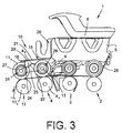
- ein Streckwerk mit einer dritten Ausführungsform einer Verdichtungszone.
- Fig.1
- a drafting system for warping roving, with a first formation of a compression zone according to the invention,
- Fig.2
- a drafting system with a second embodiment of a compression zone,
- Figure 3
- a drafting system with a third embodiment of a compression zone.
Das in
Die in der Regel maschinenlangen, beispielsweise durch einen maschinenendseitig angeordneten Antrieb sowie eine entsprechende Getriebeanordnung mit unterschiedlichen Rotationsgeschwindigkeiten angetriebenen Unterwalzen sind über (nicht dargestellte) Stanzen am Maschinengestell der Ringspinnmaschine gelagert, während die Oberwalzen, die während des Spinnbetriebes von den Unterwalzen reibschlüssig angetrieben werden, jeweils über so genannte Lenker an einem Pendelträger 5 angeschlossen sind, der seinerseits über eine Stütze 28 an einer am Maschinengestell befestigten Haltestange 12 festgelegt ist.The generally machine-length, for example, by a machine end side arranged drive and a corresponding gear assembly with different rotational speeds driven lower rollers are mounted on (not shown) punching on the machine frame of the ring spinning machine, while the upper rollers which are frictionally driven by the lower rollers during the spinning operation, respectively are connected via so-called handlebars to a
Die Pendelträger 5 können mittels eines Bedienhebels 6 in den Stellungen "Streckwerk hochgeklappt" oder "Streckwerk belastet" positioniert werden, wobei sich eine dritte Stellung "Streckwerk entlastet" einstellt, wenn die Oberwalzen auf den Unterwalzen aufliegen, ohne dass der Bedienhebel 6 in seiner Schließstellung steht.The
Derartige Streckwerke 1 weisen zwischen dem Eingangswalzenpaar 2 und dem Ausgangswalzenpaar 4 eine Verzugszone 30 auf, in der das zugeführte Vorgarn 26 vorzugsweise bis zum 50fachen seiner Eingangslänge verzogen wird.
Die Verzugszone 30 ist dabei in das zwischen dem Eingangswalzenpaar 2 und dem Mittelwalzenpaar 3 liegende Vorverzugsfeld 7 und das zwischen dem Mittelwalzenpaar 3 und dem Ausgangswalzenpaar 4 liegende Hauptverzugsfeld 8 aufgeteilt.The drafting
An die Verzugszone 30 schließt sich eine Verdichtungszone 10 an, die zwischen dem Ausgangswalzenpaar 4 und dem Lieferwalzenpaar 11 liegt.At the
Wie aus
Neben dem Sattelstück der Achse 13 ist mit einer ersten Führungs- und Aufnahmeeinrichtung 29 mit Spiel ein Käfigelement 25 angeordnet.In addition to the saddle piece of the
Das Käfigelement 25 weist außer der ersten Führungs- und Aufnahmeeinrichtung 29 für die Achse 13 des Ausgangsoberwalzenpaares 4o noch eine zweite Führungs- und Aufnahmeeinrichtung 31 für die Achse 17 des Lieferoberwalzenpaares 11o sowie eine Führungseinrichtung 19 für ein bewegliches Zwischenglied 16 auf.The
Das im Käfigelement 25 in der Führungseinrichtung 19 verschiebbar gelagerte Zwischenglied 16 ist als Rollkörper ausgebildet und wird im Montagezustand durch den freien Schenkel 21 einer L-förmig ausgebildeten Belastungsfeder 15 beaufschlagt, die mit ihrem zweiten Schenkel 20 stationär am Pendelträger 5 des Streckwerks 1 befestigt ist.The displaceably mounted in the
Das bedeutet, zwischen dem freien Schenkel 21 der Belastungsfeder 15 und dem das Lieferoberwalzenpaar 11o tragenden Käfigelement 25 ist keinerlei Haftreibung gegeben, so dass eine nahezu hysteresefreie Übertragung der über die Belastungsfeder 15 vorgegebenen Belastungskraft auf das Käfigelement 25 und damit auf das Lieferoberwalzenpaar 11o, auch bei einem unrunden Lauf des Lieferwalzenunterpaares 11u, gewährleistet ist.This means, between the
Die
Wie ersichtlich, ist auch bei dieser Ausführungsform auf der Achse 13 des Ausgangsoberwalzenpaares 4o mit einer ersten Führungs- und Aufnahmeeinrichtung 29 ein Käfigelement 25 abgestützt, das außer der ersten Führungs- und Aufnahmeeinrichtung 29 noch eine zweite Führungs- und Aufnahmeeinrichtung 31 für die Achse 17 des Lieferoberwalzenpaares 11o aufweist.As can be seen, a
Wie beim ersten Ausführungsbeispiel liegt auch hier der lichte Durchmesser der ersten Führungs- und Aufnahmeeinrichtung 29 über dem Durchmesser der Achse 13.As in the first embodiment, the clear diameter of the first guiding and receiving
Beim vorliegenden Ausführungsbeispiel fungiert die Achse 17 als bewegliches Zwischenglied und ist aus diesem Grunde frei drehbar in der zweiten Führungs- und Aufnahmeeinrichtung 31 des Käfigelements 25 gelagert.In the present embodiment, the
Das heißt, die frei drehbar gelagerte Achse 17 wird durch den freien Schenkel 21 einer L-förmig ausgebildeten Belastungsfeder 15 beaufschlagt, wobei der freie Schenkel 21 vorzugsweise doppelt abgewinkelt ist.That is, the freely rotatably mounted
Die Belastungsfeder 15 ist auch hier mit ihrem zweiten Schenkel 20 stationär am Pendelträger 5 des Streckwerks 1 festgelegt.The
Die drehbare Lagerung der als Zwischenglied fungierenden Achse 17 des Lieferwalzenoberpaares 11o ermöglicht auch hier eine fast hysteresefreie Übertragung der durch die Belastungsfeder 15 vorgegebenen Belastungskraft auf das Lieferoberwalzenpaar 11o, wobei die jeweils wirksame Belastungskraft nahezu unabhängig von den Rundlaufeigenschaften des Lieferwalzenunterpaares 11u ist.The rotatable mounting of acting as an
Bei dem in
Auch der Lenker 18 wird durch den freien Schenkel 21 einer L-förmig ausgebildeten Belastungsfeder 15 beaufschlagt, welche mit ihrem zweiten Schenkel 20, ähnlich wie bei den vorstehend beschriebenen Ausführungsbeispielen, stationär am Pendelträger 5 festgelegt ist.Also, the
Die bewegliche Anordnung des als Zwischenglied fungierenden Lenkers 18 verhindert auch hier zuverlässig, dass es, insbesondere bei einem unrunden Lauf der Lieferunterwalzen 11u, im Zusammenhang mit der Arbeit der Belastungsfeder 15 zum Auftreten von Haftreibung kommen kann.The movable arrangement of acting as an
Claims (7)
- Stretching unit (1) for stretching a roving (26) with warping fields (7, 8) formed by inlet, middle and outlet roller pairs (2, 3, 4) and a connected compaction area (10), wherein upper delivery rollers (11o) are connected to the upper outlet rollers (4o) by a cage element (25) which upper outlet rollers (4o) are connected by a spring-loaded withdrawal connecting rod (9) to a pendulum carrier (5) of the stretching unit (1), and the cage element (25) is pressurised by a load spring (15), designed as a leaf spring, in the direction of the lower delivery roller (11 u),
characterised in that
the cage element (25) comprises a first guiding and receiving unit (29), the inside diameter of which is slightly over the diameter of an axle (13) of the upper outlet roller pair (4o), on which the cage element (25) is mounted and
in that the load spring (15) is connected at one end fixed onto the pendulum carrier (5) and is connected movably in the region of its opposite, free end (14) via a connecting link (16, 17, 18) to the cage element (25) receiving the upper delivery roller (11o). - Stretching unit according to claim 1, characterised in that the connecting link is designed as a roller body (16), which is mounted movably in a guiding device (19) of the cage element (25).
- Stretching unit according to claim 1, characterised in that the loading spring (15) is designed as an L-shaped angled leaf spring, the first leg (20) of which is fixed to be stationary on the pendulum carrier (5) and the second, free leg (21) of which rests on the connecting link (16, 17, 18).
- Stretching unit according to claim 1, characterised in that the connecting link pressurised by the load spring (15) is formed by an axle (17) of the upper delivery roller (11o) which is mounted rotatably in a guiding and receiving unit (31) of the cage element (25).
- Stretching unit according to claim 4, characterised in that the guiding and receiving unit (31) is designed as a fork guide, the longitudinal direction of which is tangential to a circular path that the upper delivery roller (11o) follows during an upwards and downwards movement around the upper outlet roller (4o) and which enables a movement of the axle (17) of the upper delivery roller (11o) in the fork guide.
- Stretching unit according to claim 4, characterised in that the axle (17) of the upper delivery roller (11o) is pressurised by an L-shaped angled load spring (15), wherein the free leg (21) of the load spring (15) lying on the axle (17) of the upper delivery roller (11o) is angled twice.
- Stretching unit according to claim 1, characterised in that the connecting link is designed as a driver (18) which is rounded on both its end faces (23, 24) and, pressurised by the load spring (15), is mounted in a recess (27) of the cage element (25) to be movable to a limited degree.
Applications Claiming Priority (1)
| Application Number | Priority Date | Filing Date | Title |
|---|---|---|---|
| DE102012003180A DE102012003180A1 (en) | 2012-02-17 | 2012-02-17 | Drafting system for warping a roving |
Related Parent Applications (1)
| Application Number | Title | Priority Date | Filing Date |
|---|---|---|---|
| DE102012003180 Previously-Filed-Application | 2012-02-17 |
Publications (3)
| Publication Number | Publication Date |
|---|---|
| EP2628829A2 EP2628829A2 (en) | 2013-08-21 |
| EP2628829A3 EP2628829A3 (en) | 2015-04-15 |
| EP2628829B1 true EP2628829B1 (en) | 2016-07-27 |
Family
ID=47563162
Family Applications (1)
| Application Number | Title | Priority Date | Filing Date |
|---|---|---|---|
| EP13000160.5A Active EP2628829B1 (en) | 2012-02-17 | 2013-01-14 | Stretching unit for stretching a rove |
Country Status (8)
| Country | Link |
|---|---|
| EP (1) | EP2628829B1 (en) |
| JP (1) | JP6120602B2 (en) |
| CN (1) | CN103255512B (en) |
| DE (1) | DE102012003180A1 (en) |
| ES (1) | ES2585249T3 (en) |
| IN (1) | IN2013MU00164A (en) |
| RU (1) | RU2620490C2 (en) |
| TW (1) | TWI631247B (en) |
Families Citing this family (1)
| Publication number | Priority date | Publication date | Assignee | Title |
|---|---|---|---|---|
| DE102015110691A1 (en) * | 2015-07-02 | 2017-01-05 | Maschinenfabrik Rieter Ag | Aggregate for a ring spinning machine |
Family Cites Families (10)
| Publication number | Priority date | Publication date | Assignee | Title |
|---|---|---|---|---|
| EP0159395A1 (en) * | 1981-04-06 | 1985-10-30 | Maschinenfabrik Rieter Ag | Method for drafting a roving in a spinning machine |
| DE19860201B4 (en) * | 1998-12-24 | 2008-12-18 | Maschinenfabrik Rieter Ag | Device for spinning a thread of several thread components |
| DE10005387A1 (en) | 2000-02-07 | 2001-08-09 | Stahlecker Fritz | The sliver condensing station for drawn sliver to be fed to a spinner has a sliver clamping action at the final drawing rollers and a clamping roller at the end of the suction zone with structured pressure springs acting on the rollers |
| DE10008130A1 (en) * | 2000-02-22 | 2001-08-23 | Stahlecker Fritz | Device on a spinning machine for compacting a fiber structure |
| DE10016655A1 (en) * | 2000-04-04 | 2001-10-11 | Stahlecker Fritz | Sliver drawing unit, for a spinner, comprises paired pressure rollers at the sliver condensing zone, with a common intermediate gearing drive encapsulated within a shrouding housing, for protection against fiber debris |
| EP1501967B1 (en) * | 2002-05-08 | 2009-04-22 | Holding für Industriebeteiligungen AG | Drafting assembly for a ring spinning frame comprising a compressor for a fibre band |
| DE102008057617A1 (en) * | 2008-04-24 | 2009-11-05 | Wilhelm Stahlecker Gmbh | Compressor unit and pressure roller unit for a drafting system of a textile machine |
| DE102009050581A1 (en) | 2009-10-24 | 2011-04-28 | Oerlikon Textile Components Gmbh | Compaction unit for a drafting system for warping staple fibers |
| DE102010034314A1 (en) * | 2010-08-13 | 2012-02-16 | Wilhelm Stahlecker Gmbh | System for drafting staple fiber strand, has printing rollers that are arranged on common roll provided with leaf spring used for generating spring force |
| CN201924114U (en) * | 2011-01-14 | 2011-08-10 | 常德市恒天纺织机械有限公司 | Gripping mechanism for plate spring cradle upper roller |
-
2012
- 2012-02-17 DE DE102012003180A patent/DE102012003180A1/en not_active Withdrawn
-
2013
- 2013-01-14 EP EP13000160.5A patent/EP2628829B1/en active Active
- 2013-01-14 ES ES13000160.5T patent/ES2585249T3/en active Active
- 2013-01-18 IN IN164MU2013 patent/IN2013MU00164A/en unknown
- 2013-02-08 TW TW102105023A patent/TWI631247B/en not_active IP Right Cessation
- 2013-02-08 CN CN201310079423.2A patent/CN103255512B/en active Active
- 2013-02-15 RU RU2013106668A patent/RU2620490C2/en active
- 2013-02-18 JP JP2013028557A patent/JP6120602B2/en active Active
Also Published As
| Publication number | Publication date |
|---|---|
| DE102012003180A1 (en) | 2013-08-22 |
| ES2585249T3 (en) | 2016-10-04 |
| CN103255512A (en) | 2013-08-21 |
| TWI631247B (en) | 2018-08-01 |
| TW201402894A (en) | 2014-01-16 |
| EP2628829A2 (en) | 2013-08-21 |
| CN103255512B (en) | 2017-04-26 |
| JP6120602B2 (en) | 2017-04-26 |
| RU2013106668A (en) | 2014-08-20 |
| JP2013170345A (en) | 2013-09-02 |
| RU2620490C2 (en) | 2017-05-25 |
| EP2628829A3 (en) | 2015-04-15 |
| IN2013MU00164A (en) | 2015-07-10 |
Similar Documents
| Publication | Publication Date | Title |
|---|---|---|
| CH699218A2 (en) | Apparatus and method for monitoring for the production of core yarn. | |
| DE10344163B9 (en) | Method and device for producing coregarn or cortex yarn | |
| DE19815051A1 (en) | Spinning machine with a drafting device having a suction rotor | |
| DE10236450A1 (en) | Spinning machine with multi-stage drafting compression unit has a speed control unit linked to the drafting roller drive | |
| WO2019115272A1 (en) | Device for compacting a sliver, and drafting unit | |
| EP2628829B1 (en) | Stretching unit for stretching a rove | |
| DE3021632A1 (en) | SPinning machine, preferably ring spinning machine | |
| CH697799A2 (en) | Drafting and lower roller bearing slide. | |
| EP3730681A1 (en) | Apron drafting device | |
| EP2314742A2 (en) | Compacting device for a stretcher for stretching staple fibres | |
| EP0165444B1 (en) | Drive for a waxing device and method for driving such a device | |
| EP3812491B1 (en) | Condensing guide for a drafting frame of a spinning machine and drafting frame | |
| DE10008130A1 (en) | Device on a spinning machine for compacting a fiber structure | |
| DE102007003158A1 (en) | Three- roller-drafting unit arrangement i.e. Dual-apron-drafting unit arrangement, for knitting machine, has deflection elements and holding element combined as single piece component, where holding element is fixed at support arm | |
| DE102006006504B4 (en) | Drawing process and drafting device for refining fiber material | |
| EP2628828B1 (en) | Drafting unit for drafting a roving | |
| EP0099973A1 (en) | Drawing frame for a spinning machine | |
| DE102015009500A1 (en) | Method for operating a ring spinning machine, ring spinning machine and drafting system | |
| DE4230317C2 (en) | Double apron drafting system for a spinning machine | |
| CH711154A1 (en) | Variable cage for a pressure roller pair of a drafting unit. | |
| WO2019115265A1 (en) | Drawing frame for a spinning machine comprising a compaction device | |
| WO2019115267A1 (en) | Drawing frame for a spinning machine having a compacting device | |
| DE102015007222A1 (en) | Drafting for a roving and roving machine with at least one such drafting | |
| LU102828B1 (en) | Upper apron holder for an apron drafting system of a textile machine | |
| DE102004038821A1 (en) | Textile machine drafting station has two sets of drafting rollers with adjustable mutual separation |
Legal Events
| Date | Code | Title | Description |
|---|---|---|---|
| PUAI | Public reference made under article 153(3) epc to a published international application that has entered the european phase |
Free format text: ORIGINAL CODE: 0009012 |
|
| AK | Designated contracting states |
Kind code of ref document: A2 Designated state(s): AL AT BE BG CH CY CZ DE DK EE ES FI FR GB GR HR HU IE IS IT LI LT LU LV MC MK MT NL NO PL PT RO RS SE SI SK SM TR |
|
| AX | Request for extension of the european patent |
Extension state: BA ME |
|
| RAP1 | Party data changed (applicant data changed or rights of an application transferred) |
Owner name: SAURER COMPONENTS GMBH |
|
| PUAL | Search report despatched |
Free format text: ORIGINAL CODE: 0009013 |
|
| AK | Designated contracting states |
Kind code of ref document: A3 Designated state(s): AL AT BE BG CH CY CZ DE DK EE ES FI FR GB GR HR HU IE IS IT LI LT LU LV MC MK MT NL NO PL PT RO RS SE SI SK SM TR |
|
| AX | Request for extension of the european patent |
Extension state: BA ME |
|
| RIC1 | Information provided on ipc code assigned before grant |
Ipc: D01H 5/50 20060101AFI20150310BHEP Ipc: D01H 5/26 20060101ALI20150310BHEP |
|
| 17P | Request for examination filed |
Effective date: 20151015 |
|
| RBV | Designated contracting states (corrected) |
Designated state(s): AL AT BE BG CH CY CZ DE DK EE ES FI FR GB GR HR HU IE IS IT LI LT LU LV MC MK MT NL NO PL PT RO RS SE SI SK SM TR |
|
| GRAP | Despatch of communication of intention to grant a patent |
Free format text: ORIGINAL CODE: EPIDOSNIGR1 |
|
| INTG | Intention to grant announced |
Effective date: 20160411 |
|
| GRAS | Grant fee paid |
Free format text: ORIGINAL CODE: EPIDOSNIGR3 |
|
| GRAA | (expected) grant |
Free format text: ORIGINAL CODE: 0009210 |
|
| AK | Designated contracting states |
Kind code of ref document: B1 Designated state(s): AL AT BE BG CH CY CZ DE DK EE ES FI FR GB GR HR HU IE IS IT LI LT LU LV MC MK MT NL NO PL PT RO RS SE SI SK SM TR |
|
| REG | Reference to a national code |
Ref country code: GB Ref legal event code: FG4D Free format text: NOT ENGLISH |
|
| REG | Reference to a national code |
Ref country code: CH Ref legal event code: EP |
|
| REG | Reference to a national code |
Ref country code: AT Ref legal event code: REF Ref document number: 815877 Country of ref document: AT Kind code of ref document: T Effective date: 20160815 |
|
| REG | Reference to a national code |
Ref country code: IE Ref legal event code: FG4D Free format text: LANGUAGE OF EP DOCUMENT: GERMAN |
|
| REG | Reference to a national code |
Ref country code: DE Ref legal event code: R096 Ref document number: 502013003839 Country of ref document: DE |
|
| REG | Reference to a national code |
Ref country code: ES Ref legal event code: FG2A Ref document number: 2585249 Country of ref document: ES Kind code of ref document: T3 Effective date: 20161004 |
|
| REG | Reference to a national code |
Ref country code: LT Ref legal event code: MG4D |
|
| REG | Reference to a national code |
Ref country code: NL Ref legal event code: MP Effective date: 20160727 |
|
| PG25 | Lapsed in a contracting state [announced via postgrant information from national office to epo] |
Ref country code: LT Free format text: LAPSE BECAUSE OF FAILURE TO SUBMIT A TRANSLATION OF THE DESCRIPTION OR TO PAY THE FEE WITHIN THE PRESCRIBED TIME-LIMIT Effective date: 20160727 Ref country code: FI Free format text: LAPSE BECAUSE OF FAILURE TO SUBMIT A TRANSLATION OF THE DESCRIPTION OR TO PAY THE FEE WITHIN THE PRESCRIBED TIME-LIMIT Effective date: 20160727 Ref country code: RS Free format text: LAPSE BECAUSE OF FAILURE TO SUBMIT A TRANSLATION OF THE DESCRIPTION OR TO PAY THE FEE WITHIN THE PRESCRIBED TIME-LIMIT Effective date: 20160727 Ref country code: IS Free format text: LAPSE BECAUSE OF FAILURE TO SUBMIT A TRANSLATION OF THE DESCRIPTION OR TO PAY THE FEE WITHIN THE PRESCRIBED TIME-LIMIT Effective date: 20161127 Ref country code: NL Free format text: LAPSE BECAUSE OF FAILURE TO SUBMIT A TRANSLATION OF THE DESCRIPTION OR TO PAY THE FEE WITHIN THE PRESCRIBED TIME-LIMIT Effective date: 20160727 Ref country code: NO Free format text: LAPSE BECAUSE OF FAILURE TO SUBMIT A TRANSLATION OF THE DESCRIPTION OR TO PAY THE FEE WITHIN THE PRESCRIBED TIME-LIMIT Effective date: 20161027 Ref country code: HR Free format text: LAPSE BECAUSE OF FAILURE TO SUBMIT A TRANSLATION OF THE DESCRIPTION OR TO PAY THE FEE WITHIN THE PRESCRIBED TIME-LIMIT Effective date: 20160727 |
|
| PG25 | Lapsed in a contracting state [announced via postgrant information from national office to epo] |
Ref country code: SE Free format text: LAPSE BECAUSE OF FAILURE TO SUBMIT A TRANSLATION OF THE DESCRIPTION OR TO PAY THE FEE WITHIN THE PRESCRIBED TIME-LIMIT Effective date: 20160727 Ref country code: GR Free format text: LAPSE BECAUSE OF FAILURE TO SUBMIT A TRANSLATION OF THE DESCRIPTION OR TO PAY THE FEE WITHIN THE PRESCRIBED TIME-LIMIT Effective date: 20161028 Ref country code: PL Free format text: LAPSE BECAUSE OF FAILURE TO SUBMIT A TRANSLATION OF THE DESCRIPTION OR TO PAY THE FEE WITHIN THE PRESCRIBED TIME-LIMIT Effective date: 20160727 Ref country code: PT Free format text: LAPSE BECAUSE OF FAILURE TO SUBMIT A TRANSLATION OF THE DESCRIPTION OR TO PAY THE FEE WITHIN THE PRESCRIBED TIME-LIMIT Effective date: 20161128 Ref country code: LV Free format text: LAPSE BECAUSE OF FAILURE TO SUBMIT A TRANSLATION OF THE DESCRIPTION OR TO PAY THE FEE WITHIN THE PRESCRIBED TIME-LIMIT Effective date: 20160727 |
|
| PG25 | Lapsed in a contracting state [announced via postgrant information from national office to epo] |
Ref country code: EE Free format text: LAPSE BECAUSE OF FAILURE TO SUBMIT A TRANSLATION OF THE DESCRIPTION OR TO PAY THE FEE WITHIN THE PRESCRIBED TIME-LIMIT Effective date: 20160727 Ref country code: RO Free format text: LAPSE BECAUSE OF FAILURE TO SUBMIT A TRANSLATION OF THE DESCRIPTION OR TO PAY THE FEE WITHIN THE PRESCRIBED TIME-LIMIT Effective date: 20160727 |
|
| REG | Reference to a national code |
Ref country code: DE Ref legal event code: R097 Ref document number: 502013003839 Country of ref document: DE |
|
| PG25 | Lapsed in a contracting state [announced via postgrant information from national office to epo] |
Ref country code: BG Free format text: LAPSE BECAUSE OF FAILURE TO SUBMIT A TRANSLATION OF THE DESCRIPTION OR TO PAY THE FEE WITHIN THE PRESCRIBED TIME-LIMIT Effective date: 20161027 Ref country code: BE Free format text: LAPSE BECAUSE OF NON-PAYMENT OF DUE FEES Effective date: 20170131 Ref country code: SM Free format text: LAPSE BECAUSE OF FAILURE TO SUBMIT A TRANSLATION OF THE DESCRIPTION OR TO PAY THE FEE WITHIN THE PRESCRIBED TIME-LIMIT Effective date: 20160727 Ref country code: SK Free format text: LAPSE BECAUSE OF FAILURE TO SUBMIT A TRANSLATION OF THE DESCRIPTION OR TO PAY THE FEE WITHIN THE PRESCRIBED TIME-LIMIT Effective date: 20160727 Ref country code: DK Free format text: LAPSE BECAUSE OF FAILURE TO SUBMIT A TRANSLATION OF THE DESCRIPTION OR TO PAY THE FEE WITHIN THE PRESCRIBED TIME-LIMIT Effective date: 20160727 |
|
| PLBE | No opposition filed within time limit |
Free format text: ORIGINAL CODE: 0009261 |
|
| STAA | Information on the status of an ep patent application or granted ep patent |
Free format text: STATUS: NO OPPOSITION FILED WITHIN TIME LIMIT |
|
| 26N | No opposition filed |
Effective date: 20170502 |
|
| PG25 | Lapsed in a contracting state [announced via postgrant information from national office to epo] |
Ref country code: SI Free format text: LAPSE BECAUSE OF FAILURE TO SUBMIT A TRANSLATION OF THE DESCRIPTION OR TO PAY THE FEE WITHIN THE PRESCRIBED TIME-LIMIT Effective date: 20160727 |
|
| GBPC | Gb: european patent ceased through non-payment of renewal fee |
Effective date: 20170114 |
|
| PG25 | Lapsed in a contracting state [announced via postgrant information from national office to epo] |
Ref country code: MC Free format text: LAPSE BECAUSE OF FAILURE TO SUBMIT A TRANSLATION OF THE DESCRIPTION OR TO PAY THE FEE WITHIN THE PRESCRIBED TIME-LIMIT Effective date: 20160727 |
|
| REG | Reference to a national code |
Ref country code: FR Ref legal event code: ST Effective date: 20170929 |
|
| PG25 | Lapsed in a contracting state [announced via postgrant information from national office to epo] |
Ref country code: FR Free format text: LAPSE BECAUSE OF NON-PAYMENT OF DUE FEES Effective date: 20170131 |
|
| REG | Reference to a national code |
Ref country code: IE Ref legal event code: MM4A |
|
| PG25 | Lapsed in a contracting state [announced via postgrant information from national office to epo] |
Ref country code: GB Free format text: LAPSE BECAUSE OF NON-PAYMENT OF DUE FEES Effective date: 20170114 Ref country code: LU Free format text: LAPSE BECAUSE OF NON-PAYMENT OF DUE FEES Effective date: 20170114 |
|
| REG | Reference to a national code |
Ref country code: BE Ref legal event code: MM Effective date: 20170131 |
|
| PG25 | Lapsed in a contracting state [announced via postgrant information from national office to epo] |
Ref country code: IE Free format text: LAPSE BECAUSE OF NON-PAYMENT OF DUE FEES Effective date: 20170114 |
|
| REG | Reference to a national code |
Ref country code: DE Ref legal event code: R081 Ref document number: 502013003839 Country of ref document: DE Owner name: SAURER SPINNING SOLUTIONS GMBH & CO. KG, DE Free format text: FORMER OWNER: SAURER COMPONENTS GMBH, 70736 FELLBACH, DE |
|
| PG25 | Lapsed in a contracting state [announced via postgrant information from national office to epo] |
Ref country code: MT Free format text: LAPSE BECAUSE OF FAILURE TO SUBMIT A TRANSLATION OF THE DESCRIPTION OR TO PAY THE FEE WITHIN THE PRESCRIBED TIME-LIMIT Effective date: 20160727 |
|
| PG25 | Lapsed in a contracting state [announced via postgrant information from national office to epo] |
Ref country code: AL Free format text: LAPSE BECAUSE OF FAILURE TO SUBMIT A TRANSLATION OF THE DESCRIPTION OR TO PAY THE FEE WITHIN THE PRESCRIBED TIME-LIMIT Effective date: 20160727 |
|
| REG | Reference to a national code |
Ref country code: AT Ref legal event code: MM01 Ref document number: 815877 Country of ref document: AT Kind code of ref document: T Effective date: 20180114 |
|
| REG | Reference to a national code |
Ref country code: ES Ref legal event code: PC2A Owner name: SAURER SPINNING SOLUTIONS GMBH & CO. KG Effective date: 20190327 |
|
| PG25 | Lapsed in a contracting state [announced via postgrant information from national office to epo] |
Ref country code: AT Free format text: LAPSE BECAUSE OF NON-PAYMENT OF DUE FEES Effective date: 20180114 |
|
| PG25 | Lapsed in a contracting state [announced via postgrant information from national office to epo] |
Ref country code: HU Free format text: LAPSE BECAUSE OF FAILURE TO SUBMIT A TRANSLATION OF THE DESCRIPTION OR TO PAY THE FEE WITHIN THE PRESCRIBED TIME-LIMIT; INVALID AB INITIO Effective date: 20130114 |
|
| PG25 | Lapsed in a contracting state [announced via postgrant information from national office to epo] |
Ref country code: CY Free format text: LAPSE BECAUSE OF NON-PAYMENT OF DUE FEES Effective date: 20160727 |
|
| PG25 | Lapsed in a contracting state [announced via postgrant information from national office to epo] |
Ref country code: MK Free format text: LAPSE BECAUSE OF FAILURE TO SUBMIT A TRANSLATION OF THE DESCRIPTION OR TO PAY THE FEE WITHIN THE PRESCRIBED TIME-LIMIT Effective date: 20160727 |
|
| PGFP | Annual fee paid to national office [announced via postgrant information from national office to epo] |
Ref country code: CZ Payment date: 20221221 Year of fee payment: 11 |
|
| PGFP | Annual fee paid to national office [announced via postgrant information from national office to epo] |
Ref country code: ES Payment date: 20230201 Year of fee payment: 11 Ref country code: CH Payment date: 20230125 Year of fee payment: 11 |
|
| PGFP | Annual fee paid to national office [announced via postgrant information from national office to epo] |
Ref country code: TR Payment date: 20230110 Year of fee payment: 11 Ref country code: IT Payment date: 20230131 Year of fee payment: 11 Ref country code: DE Payment date: 20230126 Year of fee payment: 11 |
|
| PGFP | Annual fee paid to national office [announced via postgrant information from national office to epo] |
Ref country code: ES Payment date: 20240216 Year of fee payment: 12 |