EP2628829B1 - Banc d'étirage destiné à étirer une mèche - Google Patents
Banc d'étirage destiné à étirer une mèche Download PDFInfo
- Publication number
- EP2628829B1 EP2628829B1 EP13000160.5A EP13000160A EP2628829B1 EP 2628829 B1 EP2628829 B1 EP 2628829B1 EP 13000160 A EP13000160 A EP 13000160A EP 2628829 B1 EP2628829 B1 EP 2628829B1
- Authority
- EP
- European Patent Office
- Prior art keywords
- cage element
- rollers
- spring
- roller
- stretching unit
- Prior art date
- Legal status (The legal status is an assumption and is not a legal conclusion. Google has not performed a legal analysis and makes no representation as to the accuracy of the status listed.)
- Active
Links
- 238000005056 compaction Methods 0.000 claims description 3
- 238000009987 spinning Methods 0.000 description 12
- 230000006835 compression Effects 0.000 description 9
- 238000007906 compression Methods 0.000 description 9
- 230000005540 biological transmission Effects 0.000 description 5
- 239000000835 fiber Substances 0.000 description 4
- 230000000694 effects Effects 0.000 description 3
- 238000007378 ring spinning Methods 0.000 description 3
- 238000005096 rolling process Methods 0.000 description 3
- 239000004753 textile Substances 0.000 description 3
- 230000015572 biosynthetic process Effects 0.000 description 2
- 230000003068 static effect Effects 0.000 description 2
- 230000003321 amplification Effects 0.000 description 1
- 238000010276 construction Methods 0.000 description 1
- 230000001419 dependent effect Effects 0.000 description 1
- 230000006866 deterioration Effects 0.000 description 1
- 230000002045 lasting effect Effects 0.000 description 1
- 238000000034 method Methods 0.000 description 1
- 238000003199 nucleic acid amplification method Methods 0.000 description 1
- 238000004080 punching Methods 0.000 description 1
- 230000000284 resting effect Effects 0.000 description 1
- 238000009420 retrofitting Methods 0.000 description 1
- 239000013589 supplement Substances 0.000 description 1
- 230000003313 weakening effect Effects 0.000 description 1
Images


Classifications
-
- D—TEXTILES; PAPER
- D01—NATURAL OR MAN-MADE THREADS OR FIBRES; SPINNING
- D01H—SPINNING OR TWISTING
- D01H5/00—Drafting machines or arrangements ; Threading of roving into drafting machine
- D01H5/18—Drafting machines or arrangements without fallers or like pinned bars
- D01H5/46—Loading arrangements
- D01H5/50—Loading arrangements using springs
-
- D—TEXTILES; PAPER
- D01—NATURAL OR MAN-MADE THREADS OR FIBRES; SPINNING
- D01H—SPINNING OR TWISTING
- D01H5/00—Drafting machines or arrangements ; Threading of roving into drafting machine
- D01H5/18—Drafting machines or arrangements without fallers or like pinned bars
- D01H5/26—Drafting machines or arrangements without fallers or like pinned bars in which fibres are controlled by one or more endless aprons
Definitions
- the invention relates to a drafting system for warping a roving according to the preamble of claim 1.
- Draw frames for warping rovings are widely used in the textile industry and are used on various textile machines.
- the work stations of ring spinning machines are equipped, for example, with drafting devices which draw a roving unwound from a flyer bobbin into a sliver of high fineness, which is subsequently provided with a twist and wound up as a finished yarn on a spinning cop.
- Such drafting systems usually have three machine-length, driven by a machine end side drive at different rotational speeds, spaced arranged lower rollers, and each three associated, arranged on a pivotally mounted pendulum carrier top rollers.
- the top rollers lie during the spinning operation with a predetermined contact pressure on the driven bottom rollers and are driven by these frictionally. That is, the upper rollers form with the associated lower rollers roller pairs, which ensure because of their different rotational speeds that the submitted roving is distorted when passing through the drafting system.
- such drafting systems typically include an input, a center and an output roller pair, the area between the input and center roller pairs forms a so-called Vorverzugsfeld, while the area between the middle and the output roller pair acts as a main drafting field.
- the supplied roving is warped in the drafting to the desired fineness and leaves the drafting at the nip of the pair of delivery rollers as a relatively wide, for example, up to 50 times warped sliver.
- this relatively wide sliver is then acted upon by a spinning spinning cop in conjunction with an associated ring traveler of the relevant work site with spin rotation and thereby twisted into a finished yarn.
- special compression devices are arranged between the pairs of output rollers and the pairs of delivery rollers, which can be designed, for example, as mechanical compressors or can operate pneumatically.
- the output top rollers arranged in front of the compaction zone and the upper top delivery rollers arranged downstream of the compaction zone are mounted in a common cage element in such a way that the axes of the roller pairs are guided parallel to one another. That is, the cage element covered with a first axis guide means the axis of the top rollers at the side of the saddle, which in turn is arranged in a so-called output link of the pendulum carrier and held there by a saddle spring.
- the output link is usually acted upon by a spring element so that the Ninoberwalzen rest with a defined contact pressure on the associated output lower rollers.
- the delivery top rollers must also rest on the delivery bottom rollers with a specific loading force, since this is the only way to ensure that the compacted fibers are properly transported even in the area of the compression zone.
- various methods or devices are known.
- the cage element with a molded surface, which is arranged and designed so that the cage element in the installed state and with closed pendulum carrier on the underside of the output link supported. That is, the loading force introduced from the output link is transmitted to the cage member via the integrally formed surface and distributed to the output top rollers and the delivery top rollers at respective intervals.
- a disadvantage of this known type of connection of delivery top rollers is, inter alia, that the output top rollers are often dug something out of their leadership and receiving device in the cage element, with the result that the top rollers are no longer exactly out, which in principle to a deterioration of the yarn quality leads.
- Retrofitting of the known drafting systems for example by a significant increase in the maximum load force of the output link, brought no lasting success, since such a significant increase in the loading force not only led to settlement effects on the top rollers, which also has a negative effect on the achievable yarn quality, but also a defined setting of the optimal loading force of the top roller pairs very difficult.
- the additional leaf spring can either, as in the DE 100 05 387 A1 described, be attached to the pendulum carrier of the drafting system, for example via a screw, or, as by the DE 10 2009 050 581 A1 known to be stationarily arranged on the cage element.
- the present invention seeks to further develop a drafting system for warping roving so that always a constant loading force can be ensured during the spinning operation even with counting for the compression zone delivery top rollers.
- the inventive construction in which the cage element has a first guide and receiving device, the lights Diameter slightly above the diameter of the axis of the pair of output rollers, on which the cage member is mounted and connected to the loading spring at one end stationary to the pendulum carrier of the drafting and in the region of its opposite, free end via a movable intermediate member with the delivery top rollers or the Morrisvorwalzen receiving cage member is connected, has the advantage that in this way a frictional bearing of the loading spring on the cage element can be largely prevented and ensured that the loading spring on the movable intermediate link quasi frictionless on the delivery top rollers or the cage element and thus also on the delivery top rollers transfers.
- the light diameter is slightly greater than the diameter of the axis on which the cage member is mounted, which is therefore with some play on their associated bearing axis, it is also ensured that the cage element almost force-free order can pivot its bearing axis.
- the intermediate member is designed as a rolling body, the is movably mounted in a guide device of the cage element.
- movably mounted rolling body works not only during the spinning operation very reliable, but also represents a cost-effective component, which has a long life.
- the loading spring is designed as an L-shaped bent leaf spring whose first leg is fixedly fixed to the pendulum carrier, while the second, free leg rests on a movable intermediate member.
- Such a trained loading spring is on the one hand securely fixed in a predetermined mounting position and on the other hand in a simple manner so positioned that a quasi-friction transmission of the loading forces is given.
- the loaded by the loading spring movable intermediate member is formed by the axis of the delivery top rollers, which is freely rotatably mounted in such a case in a second guiding and receiving device of the cage element.
- Such a design has the advantage, for example, that the loading spring presses directly on the saddle piece of the axis of the top delivery roller pair; So the loading force does not have to take the detour via the cage element.
- the arranged in the cage element guide and receiving means for the axis of Railoberwalzencrues of the cage element is designed as a fork guide whose longitudinal direction is approximately tangential to a circular path, which perform the delivery top rollers in an up and down movement around the Ninoberwalze ,
- a fork guide whose longitudinal direction is approximately tangential to a circular path, which perform the delivery top rollers in an up and down movement around the Ninoberwalze .
- a further advantageous embodiment is in particular also given when the axis of the delivery top rollers is acted upon by an L-shaped angled leaf spring, wherein the resting on the axis of the delivery top rollers free leg of the leaf spring in turn is angled twice.
- the movable intermediate member is designed as a handlebar.
- the handlebar is rounded in the region of its two end faces and is, limitedly movable and acted upon by a loading spring, in a recess of the cage element.
- Such a handlebar which is rounded at both ends, also makes possible an almost hysteresis-free transmission of a constant loading force, preferably provided by a leaf spring.
- Fig. 1 shown drafting device 1 has, as is known, via an input roller pair 2, a middle roller pair 3 and a pair of output rollers 4, wherein the pairs of rollers 2, 3, 4 are each formed by bottom rollers and associated top rollers.
- the generally machine-length for example, by a machine end side arranged drive and a corresponding gear assembly with different rotational speeds driven lower rollers are mounted on (not shown) punching on the machine frame of the ring spinning machine, while the upper rollers which are frictionally driven by the lower rollers during the spinning operation, respectively are connected via so-called handlebars to a pendulum carrier 5, which in turn is fixed via a support 28 to a holding rod 12 fixed to the machine frame.
- the pendulum carrier 5 can be positioned by means of an operating lever 6 in the positions “drafting system up” or “drafting system loaded”, with a third position “drafting relieved “adjusts when the upper rollers rest on the lower rollers without the operating lever 6 is in its closed position.
- Such drafting units 1 have between the pair of input rollers 2 and the pair of output rollers 4, a draft zone 30 in which the supplied roving 26 is preferably warped up to 50 times its input length.
- the drafting zone 30 is divided into the intermediate delay zone 7 lying between the pair of input rollers 2 and the middle roller pair 3 and the main drafting zone 8 located between the middle roller pair 3 and the pair of delivery rollers 4.
- a compression zone 10 connects, which is located between the pair of output rollers 4 and the pair of delivery rollers 11.
- the skilletoberwalzencru 4o is connected via a spring-loaded output link 9 to the pendulum carrier 5, that is, the axis 13 of the réelleoberwalzencrues 4o is secured with its saddle in a receptacle of the output link 9, preferably secured by a spring element.
- a cage element 25 is arranged with a first guiding and receiving device 29 with play.
- the cage member 25 has, in addition to the first guide and receiving means 29 for the axis 13 of Honoberwalzencrues 4o nor a second guide and receiving means 31 for the axis 17 of Dolphinoberwalzencrues 11o and a guide means 19 for a movable intermediate member 16.
- the displaceably mounted in the cage member 25 in the guide means 19 intermediate member 16 is formed as a rolling body and is in the assembled state by the free leg 21 of an L-shaped loading spring 15 is applied, which is fixed with its second leg 20 stationary on the pendulum carrier 5 of the drafting system 1.
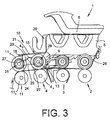
- the Fig.2 shows a second embodiment of the pendulum carrier 5 a drafting 1 arranged delay zone 10th
- a cage member 25 is also supported in this embodiment on the axis 13 of the réelleoberwalzencrues 4o with a first guide and receiving device 29, which in addition to the first guide and receiving device 29, a second guide and receiving device 31 for the axis 17 of Dolphinoberwalzencrues 11o has.
- the clear diameter of the first guiding and receiving device 29 is also above the diameter of the axis 13.
- the axis 17 acts as a movable intermediate member and is therefore freely rotatably mounted in the second guide and receiving device 31 of the cage member 25.
- the freely rotatably mounted shaft 17 is acted upon by the free leg 21 of an L-shaped loading spring 15, wherein the free leg 21 is preferably angled twice.
- the loading spring 15 is also fixed here with its second leg 20 on the pendulum carrier 5 of the drafting system 1.
- the rotatable mounting of acting as an intermediate member 17 of the delivery roller upper pair 11o also allows an almost hysteresis-free transmission of the predetermined by the loading spring 15 loading force on the Kayoberwalzencru 11o, the respective effective load force is almost independent of the concentricity of the Underwalzenunterpases 11u.
- the handlebar 18 has the front side each have a radius 23 and 24 and is limitedly movable in a recess 27 of the cage member 25 mounted.
- the handlebar 18 is acted upon by the free leg 21 of an L-shaped loading spring 15, which is fixed with its second leg 20, similar to the embodiments described above, stationary on the pendulum carrier 5.
- the movable arrangement of acting as an intermediate link arm 18 also reliably prevents that, in particular in a non-circular running of Kayunterwalzen 11u, may occur in connection with the work of the loading spring 15 to the occurrence of static friction.
Landscapes
- Engineering & Computer Science (AREA)
- Mechanical Engineering (AREA)
- Textile Engineering (AREA)
- Spinning Or Twisting Of Yarns (AREA)
- Exhaust Silencers (AREA)
Claims (7)
- Banc d'étirage (1) conçu pour étirer une mèche (26), comprenant des zones d'étirage (7, 8) formées par des paires (2, 3, 4) de cylindres d'entrée, centraux et de sortie, ainsi qu'une zone de compression (10) rapportée, des cylindres délivreurs (11o) supérieurs étant rattachés, par l'intermédiaire d'un élément (25) formant cage, aux cylindres supérieurs de sortie (40) reliés à un support oscillant (5) dudit banc d'étirage (1) par l'intermédiaire d'une biellette de sortie (9) à sollicitation par ressort, et ledit élément (25) formant cage étant sollicité, par un ressort de contrainte (15) réalisé sous la forme d'une lame de ressort, en direction de cylindres délivreurs (11u) inférieurs,
caractérisé par le fait
que l'élément (25) formant cage présente un premier dispositif (29) de guidage et de réception dont le diamètre intérieur excède légèrement le diamètre d'un axe (13) de la paire de cylindres supérieurs de sortie (40), sur lequel ledit élément (25) formant cage est monté ; et
que le ressort de contrainte (15) est rattaché par une extrémité au support oscillant (5), de manière fixe, et est relié avec mobilité dans la région de son extrémité libre (14) pointant à l'opposé, au moyen d'un organe intermédiaire (16, 17, 18), audit élément (25) formant cage qui reçoit les cylindres délivreurs (11o) supérieurs. - Banc d'étirage selon la revendication 1, caractérisé par le fait que l'organe intermédiaire est réalisé sous la forme d'un corps de roulement (16) monté, avec mobilité, dans un dispositif (19) de guidage de l'élément (25) formant cage.
- Banc d'étirage selon la revendication 1, caractérisé par le fait que le ressort de contrainte (15) est réalisé sous la forme d'une lame de ressort coudée en L dont la première branche (20) est bloquée à demeure sur le support oscillant (5), de manière fixe, et dont la seconde branche libre (21) repose sur l'organe intermédiaire (16, 17, 18).
- Banc d'étirage selon la revendication 1, caractérisé par le fait que l'organe intermédiaire, sollicité par le ressort de contrainte (15), est constitué par un axe (17) des cylindres délivreurs (11o) supérieurs qui est monté à rotation dans un dispositif (31) de guidage et de réception de l'élément (25) formant cage.
- Banc d'étirage selon la revendication 4, caractérisé par le fait que le dispositif (31) de guidage et de réception est réalisé sous la forme d'un guide fourchu dont la direction longitudinale est tangentielle à une trajectoire circulaire décrite par le cylindre délivreur (11o) supérieur, lors d'un va-et-vient vertical autour du cylindre supérieur de sortie (40), et qui autorise un mouvement de l'axe (17) des cylindres délivreurs (11o) supérieurs dans ledit guide fourchu.
- Banc d'étirage selon la revendication 4, caractérisé par le fait que l'axe (17) des cylindres délivreurs (11o) supérieurs est sollicité par un ressort de contrainte (15) coudé en L, la branche libre (21) dudit ressort de contrainte (15), reposant sur ledit axe (17) desdits cylindres délivreurs (11o) supérieurs, étant à son tour munie d'un double coude.
- Banc d'étirage selon la revendication 1, caractérisé par le fait que l'organe intermédiaire est réalisé sous la forme d'une biellette (18) qui est arrondie sur ses deux faces extrêmes (23, 24) et qui, sollicitée par le ressort de contrainte (15), est montée avec mobilité restreinte dans un évidement (27) de l'élément (25) formant cage.
Applications Claiming Priority (1)
| Application Number | Priority Date | Filing Date | Title |
|---|---|---|---|
| DE102012003180A DE102012003180A1 (de) | 2012-02-17 | 2012-02-17 | Streckwerk zum Verziehen eines Vorgarns |
Related Parent Applications (1)
| Application Number | Title | Priority Date | Filing Date |
|---|---|---|---|
| DE102012003180 Previously-Filed-Application | 2012-02-17 |
Publications (3)
| Publication Number | Publication Date |
|---|---|
| EP2628829A2 EP2628829A2 (fr) | 2013-08-21 |
| EP2628829A3 EP2628829A3 (fr) | 2015-04-15 |
| EP2628829B1 true EP2628829B1 (fr) | 2016-07-27 |
Family
ID=47563162
Family Applications (1)
| Application Number | Title | Priority Date | Filing Date |
|---|---|---|---|
| EP13000160.5A Active EP2628829B1 (fr) | 2012-02-17 | 2013-01-14 | Banc d'étirage destiné à étirer une mèche |
Country Status (8)
| Country | Link |
|---|---|
| EP (1) | EP2628829B1 (fr) |
| JP (1) | JP6120602B2 (fr) |
| CN (1) | CN103255512B (fr) |
| DE (1) | DE102012003180A1 (fr) |
| ES (1) | ES2585249T3 (fr) |
| IN (1) | IN2013MU00164A (fr) |
| RU (1) | RU2620490C2 (fr) |
| TW (1) | TWI631247B (fr) |
Families Citing this family (1)
| Publication number | Priority date | Publication date | Assignee | Title |
|---|---|---|---|---|
| DE102015110691A1 (de) * | 2015-07-02 | 2017-01-05 | Maschinenfabrik Rieter Ag | Aggregat für eine Ringspinnmaschine |
Family Cites Families (10)
| Publication number | Priority date | Publication date | Assignee | Title |
|---|---|---|---|---|
| EP0159395A1 (fr) * | 1981-04-06 | 1985-10-30 | Maschinenfabrik Rieter Ag | Procédé d'étirage d'une bande de fibres pour machines de filature |
| DE19860201B4 (de) * | 1998-12-24 | 2008-12-18 | Maschinenfabrik Rieter Ag | Vorrichtung zum Spinnen eines Fadens aus mehreren Fadenkomponenten |
| DE10005387A1 (de) | 2000-02-07 | 2001-08-09 | Stahlecker Fritz | Vorrichtung an einer Spinnmaschine zum Verdichten eines Faserverbandes |
| DE10008130A1 (de) * | 2000-02-22 | 2001-08-23 | Stahlecker Fritz | Vorrichtung an einer Spinnmaschine zum Verdichten eines Faserverbandes |
| DE10016655A1 (de) * | 2000-04-04 | 2001-10-11 | Stahlecker Fritz | Druckwalzeneinheit für ein Streckwerk einer Spinnmaschine |
| EP1501967B1 (fr) * | 2002-05-08 | 2009-04-22 | Holding für Industriebeteiligungen AG | Banc d'etirage pour metier continu a filer dote d'un element de compression pour un ruban de fibre |
| DE102008057668A1 (de) * | 2008-04-24 | 2009-10-29 | Wilhelm Stahlecker Gmbh | Verdichtereinheit für ein Streckwerk einer Textilmaschine |
| DE102009050581A1 (de) | 2009-10-24 | 2011-04-28 | Oerlikon Textile Components Gmbh | Compaktierungsaggregat für ein Streckwerk zum Verziehen von Stapelfasern |
| DE102010034314A1 (de) * | 2010-08-13 | 2012-02-16 | Wilhelm Stahlecker Gmbh | Streckwerk und Trag- und Belastungsarm dafür |
| CN201924114U (zh) * | 2011-01-14 | 2011-08-10 | 常德市恒天纺织机械有限公司 | 一种板簧摇架上罗拉握持机构 |
-
2012
- 2012-02-17 DE DE102012003180A patent/DE102012003180A1/de not_active Withdrawn
-
2013
- 2013-01-14 ES ES13000160.5T patent/ES2585249T3/es active Active
- 2013-01-14 EP EP13000160.5A patent/EP2628829B1/fr active Active
- 2013-01-18 IN IN164MU2013 patent/IN2013MU00164A/en unknown
- 2013-02-08 CN CN201310079423.2A patent/CN103255512B/zh active Active
- 2013-02-08 TW TW102105023A patent/TWI631247B/zh not_active IP Right Cessation
- 2013-02-15 RU RU2013106668A patent/RU2620490C2/ru active
- 2013-02-18 JP JP2013028557A patent/JP6120602B2/ja active Active
Also Published As
| Publication number | Publication date |
|---|---|
| RU2620490C2 (ru) | 2017-05-25 |
| TWI631247B (zh) | 2018-08-01 |
| TW201402894A (zh) | 2014-01-16 |
| IN2013MU00164A (fr) | 2015-07-10 |
| EP2628829A3 (fr) | 2015-04-15 |
| EP2628829A2 (fr) | 2013-08-21 |
| ES2585249T3 (es) | 2016-10-04 |
| CN103255512B (zh) | 2017-04-26 |
| DE102012003180A1 (de) | 2013-08-22 |
| JP2013170345A (ja) | 2013-09-02 |
| CN103255512A (zh) | 2013-08-21 |
| RU2013106668A (ru) | 2014-08-20 |
| JP6120602B2 (ja) | 2017-04-26 |
Similar Documents
| Publication | Publication Date | Title |
|---|---|---|
| CH699218A2 (de) | Vorrichtung und Verfahren zur Überwachung zur Herstellung von Coregarn. | |
| DE10344163B9 (de) | Verfahren und Vorrichtung zur Herstellung von Coregarn oder Corescheinzwirn | |
| DE19815051A1 (de) | Spinnmaschine mit einem einen Saugrotor aufweisenden Streckwerk | |
| DE10236450A1 (de) | Spinnmaschine mit einem Mehrstufen-Verdichtungs-Streckwerk | |
| WO2019115272A1 (fr) | Dispositif de compression d'un assemblage de fibres et banc d'étirage | |
| EP2628829B1 (fr) | Banc d'étirage destiné à étirer une mèche | |
| DE3021632A1 (de) | Spinnmaschine, vorzugsweise ringspinnmaschine | |
| CH697799A2 (de) | Streckwerk und Unterwalzen-Lagerschlitten. | |
| EP3730681A1 (fr) | Système d'étirage à lanières | |
| EP2314742A2 (fr) | Agrégat de compactage pour un banc d'étirage destiné à dissiper des fibres à empiler | |
| EP0165444B1 (fr) | Entraînement pour dispositif de paraffinage et procédé pour entraîner un tel dispositif | |
| EP3812491B1 (fr) | Guides condenseurs de fibres pour un banc d'étirage d'un métier à filature ainsi qu'un banc d'étirage | |
| DE10008130A1 (de) | Vorrichtung an einer Spinnmaschine zum Verdichten eines Faserverbandes | |
| DE102007003158A1 (de) | Streckwerks-Anordnung | |
| DE102006006504B4 (de) | Streckverfahren und Streckwerk zur Verfeinerung von Fasermaterial | |
| EP2628828B1 (fr) | Banc d'étirage destiné à étirer une mèche | |
| EP0099973A1 (fr) | Etirage pour machine de filature | |
| DE102015009500A1 (de) | Verfahren zum Betreiben einer Ringspinnmaschine, Ringspinnmaschine und Streckwerk | |
| DE4230317C2 (de) | Doppelriemchenstreckwerk für eine Spinnmaschine | |
| CH711154A1 (de) | Variabler Käfig für ein Druckwalzenpaar eines Streckwerks. | |
| WO2019115265A1 (fr) | Dispositif d'étirage pour un métier à filer comprenant un dispositif de compactage | |
| WO2019115267A1 (fr) | Banc d'étirage d'un métier à filer, muni d'un dispositif de compression | |
| DE102015007222A1 (de) | Streckwerk für eine Vorspinnmaschine und Vorspinnmaschine mit wenigstens einem solchen Streckwerk | |
| LU102828B1 (de) | Oberriemchenhalter für ein Riemchenstreckwerk einer Textilmaschine | |
| DE102004038821A1 (de) | Streckwerk für Spinnmaschinen |
Legal Events
| Date | Code | Title | Description |
|---|---|---|---|
| PUAI | Public reference made under article 153(3) epc to a published international application that has entered the european phase |
Free format text: ORIGINAL CODE: 0009012 |
|
| AK | Designated contracting states |
Kind code of ref document: A2 Designated state(s): AL AT BE BG CH CY CZ DE DK EE ES FI FR GB GR HR HU IE IS IT LI LT LU LV MC MK MT NL NO PL PT RO RS SE SI SK SM TR |
|
| AX | Request for extension of the european patent |
Extension state: BA ME |
|
| RAP1 | Party data changed (applicant data changed or rights of an application transferred) |
Owner name: SAURER COMPONENTS GMBH |
|
| PUAL | Search report despatched |
Free format text: ORIGINAL CODE: 0009013 |
|
| AK | Designated contracting states |
Kind code of ref document: A3 Designated state(s): AL AT BE BG CH CY CZ DE DK EE ES FI FR GB GR HR HU IE IS IT LI LT LU LV MC MK MT NL NO PL PT RO RS SE SI SK SM TR |
|
| AX | Request for extension of the european patent |
Extension state: BA ME |
|
| RIC1 | Information provided on ipc code assigned before grant |
Ipc: D01H 5/50 20060101AFI20150310BHEP Ipc: D01H 5/26 20060101ALI20150310BHEP |
|
| 17P | Request for examination filed |
Effective date: 20151015 |
|
| RBV | Designated contracting states (corrected) |
Designated state(s): AL AT BE BG CH CY CZ DE DK EE ES FI FR GB GR HR HU IE IS IT LI LT LU LV MC MK MT NL NO PL PT RO RS SE SI SK SM TR |
|
| GRAP | Despatch of communication of intention to grant a patent |
Free format text: ORIGINAL CODE: EPIDOSNIGR1 |
|
| INTG | Intention to grant announced |
Effective date: 20160411 |
|
| GRAS | Grant fee paid |
Free format text: ORIGINAL CODE: EPIDOSNIGR3 |
|
| GRAA | (expected) grant |
Free format text: ORIGINAL CODE: 0009210 |
|
| AK | Designated contracting states |
Kind code of ref document: B1 Designated state(s): AL AT BE BG CH CY CZ DE DK EE ES FI FR GB GR HR HU IE IS IT LI LT LU LV MC MK MT NL NO PL PT RO RS SE SI SK SM TR |
|
| REG | Reference to a national code |
Ref country code: GB Ref legal event code: FG4D Free format text: NOT ENGLISH |
|
| REG | Reference to a national code |
Ref country code: CH Ref legal event code: EP |
|
| REG | Reference to a national code |
Ref country code: AT Ref legal event code: REF Ref document number: 815877 Country of ref document: AT Kind code of ref document: T Effective date: 20160815 |
|
| REG | Reference to a national code |
Ref country code: IE Ref legal event code: FG4D Free format text: LANGUAGE OF EP DOCUMENT: GERMAN |
|
| REG | Reference to a national code |
Ref country code: DE Ref legal event code: R096 Ref document number: 502013003839 Country of ref document: DE |
|
| REG | Reference to a national code |
Ref country code: ES Ref legal event code: FG2A Ref document number: 2585249 Country of ref document: ES Kind code of ref document: T3 Effective date: 20161004 |
|
| REG | Reference to a national code |
Ref country code: LT Ref legal event code: MG4D |
|
| REG | Reference to a national code |
Ref country code: NL Ref legal event code: MP Effective date: 20160727 |
|
| PG25 | Lapsed in a contracting state [announced via postgrant information from national office to epo] |
Ref country code: LT Free format text: LAPSE BECAUSE OF FAILURE TO SUBMIT A TRANSLATION OF THE DESCRIPTION OR TO PAY THE FEE WITHIN THE PRESCRIBED TIME-LIMIT Effective date: 20160727 Ref country code: FI Free format text: LAPSE BECAUSE OF FAILURE TO SUBMIT A TRANSLATION OF THE DESCRIPTION OR TO PAY THE FEE WITHIN THE PRESCRIBED TIME-LIMIT Effective date: 20160727 Ref country code: RS Free format text: LAPSE BECAUSE OF FAILURE TO SUBMIT A TRANSLATION OF THE DESCRIPTION OR TO PAY THE FEE WITHIN THE PRESCRIBED TIME-LIMIT Effective date: 20160727 Ref country code: IS Free format text: LAPSE BECAUSE OF FAILURE TO SUBMIT A TRANSLATION OF THE DESCRIPTION OR TO PAY THE FEE WITHIN THE PRESCRIBED TIME-LIMIT Effective date: 20161127 Ref country code: NL Free format text: LAPSE BECAUSE OF FAILURE TO SUBMIT A TRANSLATION OF THE DESCRIPTION OR TO PAY THE FEE WITHIN THE PRESCRIBED TIME-LIMIT Effective date: 20160727 Ref country code: NO Free format text: LAPSE BECAUSE OF FAILURE TO SUBMIT A TRANSLATION OF THE DESCRIPTION OR TO PAY THE FEE WITHIN THE PRESCRIBED TIME-LIMIT Effective date: 20161027 Ref country code: HR Free format text: LAPSE BECAUSE OF FAILURE TO SUBMIT A TRANSLATION OF THE DESCRIPTION OR TO PAY THE FEE WITHIN THE PRESCRIBED TIME-LIMIT Effective date: 20160727 |
|
| PG25 | Lapsed in a contracting state [announced via postgrant information from national office to epo] |
Ref country code: SE Free format text: LAPSE BECAUSE OF FAILURE TO SUBMIT A TRANSLATION OF THE DESCRIPTION OR TO PAY THE FEE WITHIN THE PRESCRIBED TIME-LIMIT Effective date: 20160727 Ref country code: GR Free format text: LAPSE BECAUSE OF FAILURE TO SUBMIT A TRANSLATION OF THE DESCRIPTION OR TO PAY THE FEE WITHIN THE PRESCRIBED TIME-LIMIT Effective date: 20161028 Ref country code: PL Free format text: LAPSE BECAUSE OF FAILURE TO SUBMIT A TRANSLATION OF THE DESCRIPTION OR TO PAY THE FEE WITHIN THE PRESCRIBED TIME-LIMIT Effective date: 20160727 Ref country code: PT Free format text: LAPSE BECAUSE OF FAILURE TO SUBMIT A TRANSLATION OF THE DESCRIPTION OR TO PAY THE FEE WITHIN THE PRESCRIBED TIME-LIMIT Effective date: 20161128 Ref country code: LV Free format text: LAPSE BECAUSE OF FAILURE TO SUBMIT A TRANSLATION OF THE DESCRIPTION OR TO PAY THE FEE WITHIN THE PRESCRIBED TIME-LIMIT Effective date: 20160727 |
|
| PG25 | Lapsed in a contracting state [announced via postgrant information from national office to epo] |
Ref country code: EE Free format text: LAPSE BECAUSE OF FAILURE TO SUBMIT A TRANSLATION OF THE DESCRIPTION OR TO PAY THE FEE WITHIN THE PRESCRIBED TIME-LIMIT Effective date: 20160727 Ref country code: RO Free format text: LAPSE BECAUSE OF FAILURE TO SUBMIT A TRANSLATION OF THE DESCRIPTION OR TO PAY THE FEE WITHIN THE PRESCRIBED TIME-LIMIT Effective date: 20160727 |
|
| REG | Reference to a national code |
Ref country code: DE Ref legal event code: R097 Ref document number: 502013003839 Country of ref document: DE |
|
| PG25 | Lapsed in a contracting state [announced via postgrant information from national office to epo] |
Ref country code: BG Free format text: LAPSE BECAUSE OF FAILURE TO SUBMIT A TRANSLATION OF THE DESCRIPTION OR TO PAY THE FEE WITHIN THE PRESCRIBED TIME-LIMIT Effective date: 20161027 Ref country code: BE Free format text: LAPSE BECAUSE OF NON-PAYMENT OF DUE FEES Effective date: 20170131 Ref country code: SM Free format text: LAPSE BECAUSE OF FAILURE TO SUBMIT A TRANSLATION OF THE DESCRIPTION OR TO PAY THE FEE WITHIN THE PRESCRIBED TIME-LIMIT Effective date: 20160727 Ref country code: SK Free format text: LAPSE BECAUSE OF FAILURE TO SUBMIT A TRANSLATION OF THE DESCRIPTION OR TO PAY THE FEE WITHIN THE PRESCRIBED TIME-LIMIT Effective date: 20160727 Ref country code: DK Free format text: LAPSE BECAUSE OF FAILURE TO SUBMIT A TRANSLATION OF THE DESCRIPTION OR TO PAY THE FEE WITHIN THE PRESCRIBED TIME-LIMIT Effective date: 20160727 |
|
| PLBE | No opposition filed within time limit |
Free format text: ORIGINAL CODE: 0009261 |
|
| STAA | Information on the status of an ep patent application or granted ep patent |
Free format text: STATUS: NO OPPOSITION FILED WITHIN TIME LIMIT |
|
| 26N | No opposition filed |
Effective date: 20170502 |
|
| PG25 | Lapsed in a contracting state [announced via postgrant information from national office to epo] |
Ref country code: SI Free format text: LAPSE BECAUSE OF FAILURE TO SUBMIT A TRANSLATION OF THE DESCRIPTION OR TO PAY THE FEE WITHIN THE PRESCRIBED TIME-LIMIT Effective date: 20160727 |
|
| GBPC | Gb: european patent ceased through non-payment of renewal fee |
Effective date: 20170114 |
|
| PG25 | Lapsed in a contracting state [announced via postgrant information from national office to epo] |
Ref country code: MC Free format text: LAPSE BECAUSE OF FAILURE TO SUBMIT A TRANSLATION OF THE DESCRIPTION OR TO PAY THE FEE WITHIN THE PRESCRIBED TIME-LIMIT Effective date: 20160727 |
|
| REG | Reference to a national code |
Ref country code: FR Ref legal event code: ST Effective date: 20170929 |
|
| PG25 | Lapsed in a contracting state [announced via postgrant information from national office to epo] |
Ref country code: FR Free format text: LAPSE BECAUSE OF NON-PAYMENT OF DUE FEES Effective date: 20170131 |
|
| REG | Reference to a national code |
Ref country code: IE Ref legal event code: MM4A |
|
| PG25 | Lapsed in a contracting state [announced via postgrant information from national office to epo] |
Ref country code: GB Free format text: LAPSE BECAUSE OF NON-PAYMENT OF DUE FEES Effective date: 20170114 Ref country code: LU Free format text: LAPSE BECAUSE OF NON-PAYMENT OF DUE FEES Effective date: 20170114 |
|
| REG | Reference to a national code |
Ref country code: BE Ref legal event code: MM Effective date: 20170131 |
|
| PG25 | Lapsed in a contracting state [announced via postgrant information from national office to epo] |
Ref country code: IE Free format text: LAPSE BECAUSE OF NON-PAYMENT OF DUE FEES Effective date: 20170114 |
|
| REG | Reference to a national code |
Ref country code: DE Ref legal event code: R081 Ref document number: 502013003839 Country of ref document: DE Owner name: SAURER SPINNING SOLUTIONS GMBH & CO. KG, DE Free format text: FORMER OWNER: SAURER COMPONENTS GMBH, 70736 FELLBACH, DE |
|
| PG25 | Lapsed in a contracting state [announced via postgrant information from national office to epo] |
Ref country code: MT Free format text: LAPSE BECAUSE OF FAILURE TO SUBMIT A TRANSLATION OF THE DESCRIPTION OR TO PAY THE FEE WITHIN THE PRESCRIBED TIME-LIMIT Effective date: 20160727 |
|
| PG25 | Lapsed in a contracting state [announced via postgrant information from national office to epo] |
Ref country code: AL Free format text: LAPSE BECAUSE OF FAILURE TO SUBMIT A TRANSLATION OF THE DESCRIPTION OR TO PAY THE FEE WITHIN THE PRESCRIBED TIME-LIMIT Effective date: 20160727 |
|
| REG | Reference to a national code |
Ref country code: AT Ref legal event code: MM01 Ref document number: 815877 Country of ref document: AT Kind code of ref document: T Effective date: 20180114 |
|
| REG | Reference to a national code |
Ref country code: ES Ref legal event code: PC2A Owner name: SAURER SPINNING SOLUTIONS GMBH & CO. KG Effective date: 20190327 |
|
| PG25 | Lapsed in a contracting state [announced via postgrant information from national office to epo] |
Ref country code: AT Free format text: LAPSE BECAUSE OF NON-PAYMENT OF DUE FEES Effective date: 20180114 |
|
| PG25 | Lapsed in a contracting state [announced via postgrant information from national office to epo] |
Ref country code: HU Free format text: LAPSE BECAUSE OF FAILURE TO SUBMIT A TRANSLATION OF THE DESCRIPTION OR TO PAY THE FEE WITHIN THE PRESCRIBED TIME-LIMIT; INVALID AB INITIO Effective date: 20130114 |
|
| PG25 | Lapsed in a contracting state [announced via postgrant information from national office to epo] |
Ref country code: CY Free format text: LAPSE BECAUSE OF NON-PAYMENT OF DUE FEES Effective date: 20160727 |
|
| PG25 | Lapsed in a contracting state [announced via postgrant information from national office to epo] |
Ref country code: MK Free format text: LAPSE BECAUSE OF FAILURE TO SUBMIT A TRANSLATION OF THE DESCRIPTION OR TO PAY THE FEE WITHIN THE PRESCRIBED TIME-LIMIT Effective date: 20160727 |
|
| PGFP | Annual fee paid to national office [announced via postgrant information from national office to epo] |
Ref country code: TR Payment date: 20230110 Year of fee payment: 11 Ref country code: IT Payment date: 20230131 Year of fee payment: 11 |
|
| PGFP | Annual fee paid to national office [announced via postgrant information from national office to epo] |
Ref country code: ES Payment date: 20240216 Year of fee payment: 12 |
|
| PGFP | Annual fee paid to national office [announced via postgrant information from national office to epo] |
Ref country code: DE Payment date: 20240119 Year of fee payment: 12 Ref country code: CZ Payment date: 20231229 Year of fee payment: 12 Ref country code: CH Payment date: 20240202 Year of fee payment: 12 |